Embed Size (px)
Citation preview
JUMO GmbH & Co. KGDelivery address:Mackenrodtstraße 14,
36039 Fulda, GermanyPostal address: 36035 Fulda, GermanyPhone: +49 661 6003-0Fax: +49 661 6003-607E-mail: [email protected]: www.jumo.net
JUMO Instrument Co. Ltd.JUMO HouseTemple Bank, RiverwayHarlow, Essex CM20 2DY, UKPhone: +44 1279 635533Fax: +44 1279 635262E-mail: [email protected]: www.jumo.co.uk
JUMO Process Control, Inc.8 Technology BoulevardCanastota, NY 13032, USAPhone: 315-697-5866
1-800-554-JUMOFax: 315-697-5867E-mail: [email protected]: www.jumo.us
Page 1/13
2011-07-11/00540116
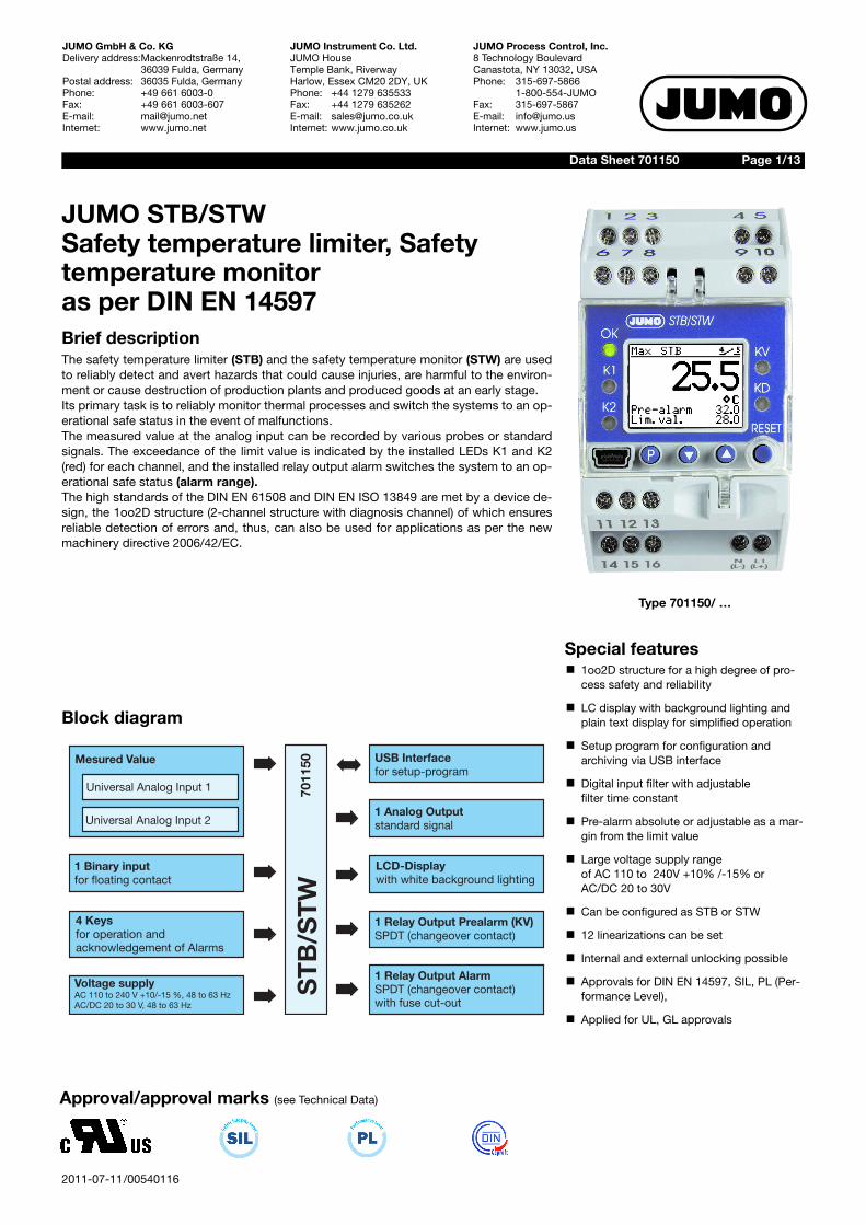
JUMO STB/STWSafety temperature limiter, Safety temperature monitoras per DIN EN 14597Brief descriptionThe safety temperature limiter (STB) and the safety temperature monitor (STW) are usedto reliably detect and avert hazards that could cause injuries, are harmful to the environ-ment or cause destruction of production plants and produced goods at an early stage.Its primary task is to reliably monitor thermal processes and switch the systems to an op-erational safe status in the event of malfunctions.The measured value at the analog input can be recorded by various probes or standardsignals. The exceedance of the limit value is indicated by the installed LEDs K1 and K2(red) for each channel, and the installed relay output alarm switches the system to an op-erational safe status (alarm range).The high standards of the DIN EN 61508 and DIN EN ISO 13849 are met by a device de-sign, the 1oo2D structure (2-channel structure with diagnosis channel) of which ensuresreliable detection of errors and, thus, can also be used for applications as per the newmachinery directive 2006/42/EC.
Block diagram
1 Binary inputfor floating contact
1 Analog Outputstandard signal
7011
50
Voltage supplyAC 110 to 240 V +10/-15 %, 48 to 63 HzAC/DC 20 to 30 V, 48 to 63 Hz
USB Interfacefor setup-program
1 Relay Output AlarmSPDT (changeover contact)with fuse cut-out
1 Relay Output Prealarm KV)(SPDT (changeover contact)
LCD-Displaywith white background lighting
ST
B/S
TW
4 Keysfor operation andacknowledgement of Alarms
Mesured Value
Universal Analog Input 1
Universal Analog Input 2
Data Sheet 701150
Type 701150/ …
Special featuresk 1oo2D structure for a high degree of pro-
cess safety and reliability
k LC display with background lighting and plain text display for simplified operation
k Setup program for configuration and archiving via USB interface
k Digital input filter with adjustablefilter time constant
k Pre-alarm absolute or adjustable as a mar-gin from the limit value
k Large voltage supply rangeof AC 110 to 240V +10% /-15% orAC/DC 20 to 30V
k Can be configured as STB or STW
k 12 linearizations can be set
k Internal and external unlocking possible
k Approvals for DIN EN 14597, SIL, PL (Per-formance Level),
k Applied for UL, GL approvals
Approval/approval marks (see Technical Data)
2011-07-11/00540116
Data Sheet 701150 Page 2/13
JUMO GmbH & Co. KGDelivery address:Mackenrodtstraße 14,
36039 Fulda, GermanyPostal address: 36035 Fulda, GermanyPhone: +49 661 6003-0Fax: +49 661 6003-607E-mail: [email protected]: www.jumo.net
JUMO Instrument Co. Ltd.JUMO HouseTemple Bank, RiverwayHarlow, Essex CM20 2DY, UKPhone: +44 1279 635533Fax: +44 1279 635262E-mail: [email protected]: www.jumo.co.uk
JUMO Process Control, Inc.8 Technology BoulevardCanastota, NY 13032, USAPhone: 315-697-5866
1-800-554-JUMOFax: 315-697-5867E-mail: [email protected]: www.jumo.us
Technical data
Analog inputsRTD temperature probe
Thermocouples
Direct current
Analog output
Designation Measuring range Accuracy2/3-wire circuit1
Ambient temperature error
Pt 100 DIN EN 60751 -200 to +850 °C 0.5% / 0.1% 50 ppm
Pt 1000 DIN EN 60751 -200 to +850 °C 0.5% / 0.1% 50 ppm
Connection type 2-wire, 3-wire circuit Maximum output resistance 30 Measuring rate 210 ms
Error tolerance time 5s time taken into account for all diagnosis tests
Input filter digital filter, 2nd priority; filter constant can be set from 0 to 100 s
Special features Individual probe Pt100 2-wire, display can also be programmed in °F
Designation Measuring range Accuracy1 Ambient temperature error
Fe-CuNi „L“ DIN 43710 -200 to +900 °C 0.4% 100 ppm
Fe-CuNi „J“ DIN EN 60584 -200 to +1200 °C 0.4% 100 ppm
Cu-CuNi „U“ DIN 43710 -200 to +600 °C 0.4% 100 ppm
Cu-CuNi „T“ DIN EN 60584 -200 to +400 °C 0.4% 100 ppm
NiCr-Ni „K“ DIN EN 60584 -200 to +1372 °C 0.4% 100 ppm
NiCrSi-NiSi „N“ DIN EN 60584 -100 to +1300 °C 0.4% 100 ppm
Pt10Rh-Pt „S“ DIN EN 60584 0 to +1768 °C 0.4% 100 ppm
Pt13Rh-Pt „R“ DIN EN 60584 0 to +1768 °C 0.4% 100 ppm
Pt30Rh-Pt6Rh „B“DIN EN 60584 300 to 1820 °C 0.4% 100 ppm
W3Re-W25Re „D“ 0 ... 2495°C 0.4% 100 ppm
Cold junction Pt 100 internal
Cold junction accuracy ± 1 K
Measuring rate 210 ms
Error tolerance time 5s time taken into account for all diagnosis tests
Input filter digital filter, 2st priority; filter constant can be set from 0 to 100 s
1. The accuracy values refer to the maximum measuring range.
Measuring range Accuracy Ambient temperature error
4 to 20 mA, voltage drop < 2 V 0.2% 150 ppm
Scaling can be freely programmed within the limits
Measuring rate 210 ms
Error tolerance time 5s time taken into account for all diagnosis tests
Input filter digital filter, 2st priority; filter constant can be set from 0 to 100 s
Special features Individual probe 4 to 20mA
Type of signal Accuracy Residual ripple Load influence Temperature error Load resistanceCurrent 4 ... 20 mA 0.5 % ± 0.5 % bei 300 ± 0.05 mA/100 150 ppm / °C 500
0 ... 20 mA
Voltage 2 ... 10 V 0.5 % ± 0.5 % ± 15 mV 150 ppm / °C 5000 ... 10 V
2011-07-11/00540116
Data Sheet 701150 Page 3/13
JUMO GmbH & Co. KGDelivery address:Mackenrodtstraße 14,
36039 Fulda, GermanyPostal address: 36035 Fulda, GermanyPhone: +49 661 6003-0Fax: +49 661 6003-607E-mail: [email protected]: www.jumo.net
JUMO Instrument Co. Ltd.JUMO HouseTemple Bank, RiverwayHarlow, Essex CM20 2DY, UKPhone: +44 1279 635533Fax: +44 1279 635262E-mail: [email protected]: www.jumo.co.uk
JUMO Process Control, Inc.8 Technology BoulevardCanastota, NY 13032, USAPhone: 315-697-5866
1-800-554-JUMOFax: 315-697-5867E-mail: [email protected]: www.jumo.us
Binary input
Relay outputs
Measuring circuit monitoring
Voltage supply
Test voltages as per EN 60730, part 1
Electrical safety
Connections Function
1 potential-free contact Unlocking, keyboard locking, level locking can be configured
Relay output KV Relay (change-over contact) without shroud 30,000 operations at a performance of 3 A /250 V, 50 Hz resistive load
Relay output alarm Change-over contactContact protection switching: safety fuse 3.15AT, installed in the NO contact arm30,000 operations at a performance of 3 A /230 V, 50 Hz resistive load
RTD temperature probe in 3-wirecircuit anddouble thermocouples
Thermocouples Current 4 to 20mA
Overrange and underrange
is detectedLED K1, K2, KD and KV are lit;">>>>“ flashes in the display for overrange, "<<<<“ for underrange.
Probe and wire break is detectedLED K1, K2, KD and KV are lit;">>>>“ flashes in the display; relay output alarm is inactive
LED K1, K2, KD and KV are lit;">>>>“ flashes in the display;relay output alarm is inactive
Probe short-circuit is detectedLED K1, K2, KD and KV are lit;"<<<<“ flashes in the display; relay output alarm is inactive
is detected by difference moni-toring of the analog inputs
LED K1, K2, KD and KV are lit;"<<<<“ flashes in the display;relay output alarm is inactive
Voltage supply AC/DC 20 to 30V, 48 to 63 Hz, AC 110 to 240V +10% /-15%, 48 to 63Hz
Power consumption < 12 VA
Input and output against voltage supply
- at a voltage supply AC 110 to 240V +10% /-15% 3.7kV/50 Hz
- at a voltage supply AC/DC 20 to 30 V, 48 to 63 Hz 3.7kV/50 Hz
Clearances / creep paths
Mains to electronic components andprobes
6 mm8 mm
Mains to relays 6 mm8 mm
Relays to electronic componentsand probes
6 mm8 mm
Electrical safety as per DIN EN 14597 (DIN EN 60730-2-9)Overvoltage category III, pollution degree 2
Protection rating I with internal separation from SELV current circuits
2011-07-11/00540116
Data Sheet 701150 Page 4/13
JUMO GmbH & Co. KGDelivery address:Mackenrodtstraße 14,
36039 Fulda, GermanyPostal address: 36035 Fulda, GermanyPhone: +49 661 6003-0Fax: +49 661 6003-607E-mail: [email protected]: www.jumo.net
JUMO Instrument Co. Ltd.JUMO HouseTemple Bank, RiverwayHarlow, Essex CM20 2DY, UKPhone: +44 1279 635533Fax: +44 1279 635262E-mail: [email protected]: www.jumo.co.uk
JUMO Process Control, Inc.8 Technology BoulevardCanastota, NY 13032, USAPhone: 315-697-5866
1-800-554-JUMOFax: 315-697-5867E-mail: [email protected]: www.jumo.us
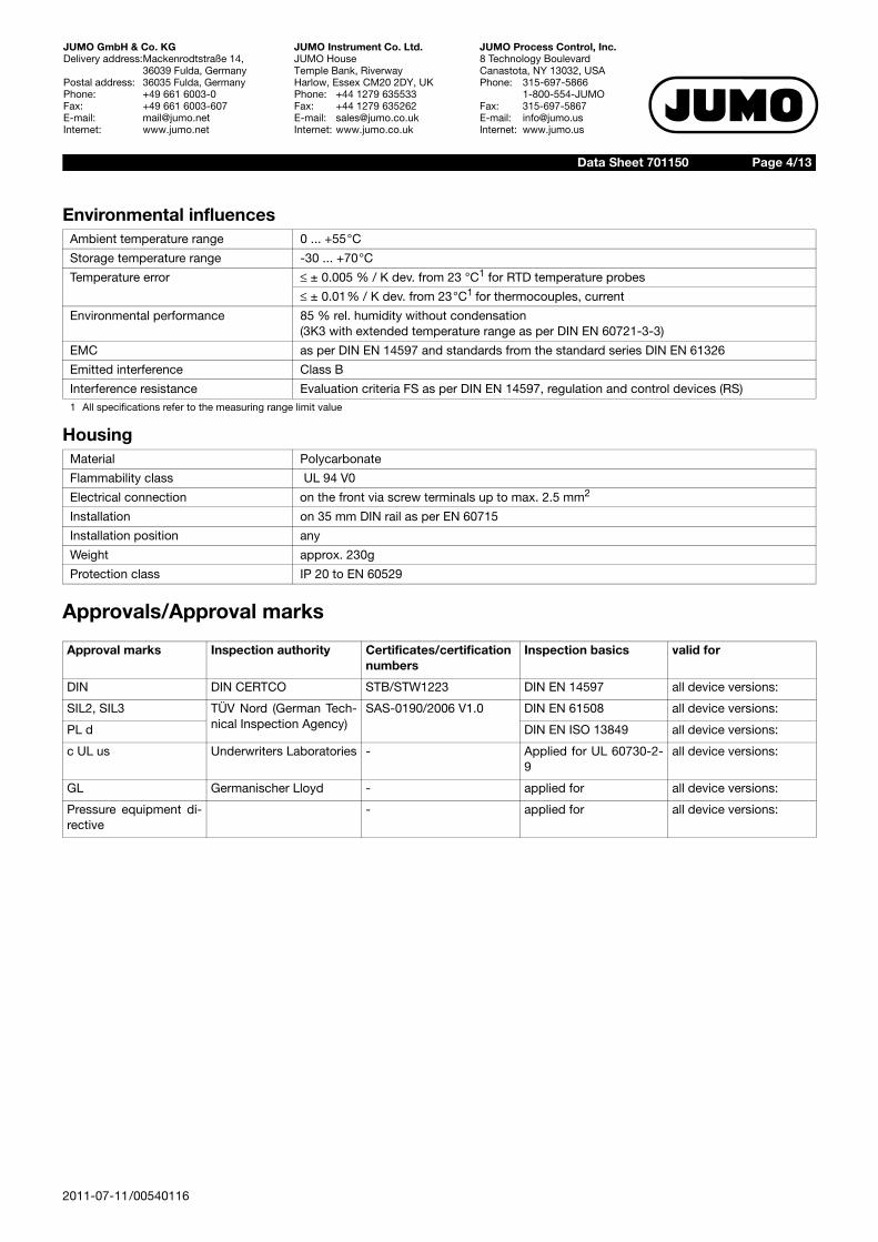
Environmental influences
Housing
Approvals/Approval marks
Ambient temperature range 0 ... +55°C
Storage temperature range -30 ... +70°C
Temperature error ± 0.005 % / K dev. from 23 °C1 for RTD temperature probes
± 0.01% / K dev. from 23°C1 for thermocouples, current
Environmental performance 85 % rel. humidity without condensation (3K3 with extended temperature range as per DIN EN 60721-3-3)
EMC as per DIN EN 14597 and standards from the standard series DIN EN 61326
Emitted interference Class B
Interference resistance Evaluation criteria FS as per DIN EN 14597, regulation and control devices (RS)1 All specifications refer to the measuring range limit value
Material Polycarbonate
Flammability class UL 94 V0
Electrical connection on the front via screw terminals up to max. 2.5 mm2
Installation on 35 mm DIN rail as per EN 60715
Installation position any
Weight approx. 230g
Protection class IP 20 to EN 60529
Approval marks Inspection authority Certificates/certificationnumbers
Inspection basics valid for
DIN DIN CERTCO STB/STW1223 DIN EN 14597 all device versions:
SIL2, SIL3 TÜV Nord (German Tech-nical Inspection Agency)
SAS-0190/2006 V1.0 DIN EN 61508 all device versions:
PL d DIN EN ISO 13849 all device versions:
c UL us Underwriters Laboratories - Applied for UL 60730-2-9
all device versions:
GL Germanischer Lloyd - applied for all device versions:
Pressure equipment di-rective
- applied for all device versions:
2011-07-11/00540116
Data Sheet 701150 Page 5/13
JUMO GmbH & Co. KGDelivery address:Mackenrodtstraße 14,
36039 Fulda, GermanyPostal address: 36035 Fulda, GermanyPhone: +49 661 6003-0Fax: +49 661 6003-607E-mail: [email protected]: www.jumo.net
JUMO Instrument Co. Ltd.JUMO HouseTemple Bank, RiverwayHarlow, Essex CM20 2DY, UKPhone: +44 1279 635533Fax: +44 1279 635262E-mail: [email protected]: www.jumo.co.uk
JUMO Process Control, Inc.8 Technology BoulevardCanastota, NY 13032, USAPhone: 315-697-5866
1-800-554-JUMOFax: 315-697-5867E-mail: [email protected]: www.jumo.us
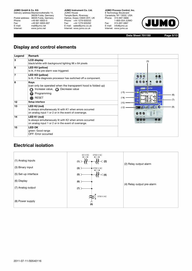
Display and control elements
Electrical isolation
Legend Remark
3 LCD displayblack/white with background lighting 96 x 64 pixels
6 LED KV (yellow) Is lit, if the pre-alarm was triggered.
7 LED KD (yellow) Is lit, if the diagnosis processor has switched off a component.
8 Keys (can only be operated when the transparent hood is folded up)
Increase value, Decrease value
Programming
RESET
12 Setup interface
13 LED K2 (red)Is always simultaneously lit with K1 when errors occurredon analog input 1 or 2 or in the event of overrange.
14 LED K1 (red)Is always simultaneously lit with K2 when errors occurredon analog input 1 or 2 or in the event of overrange.
15 LED OKgreen: Good rangeOFF: Error occurred
(1) Analog inputs
(3) Binary input
(5) Set-up interface
(6) Display
(7) Analog output
(8) Power supply
(2) Relay output alarm
(4) Relay output pre-alarm
»
3700 V AC
»
3700 V AC
(1) (2)
(4)
(3)
(5)
(8)
(6)
(7)
»
3700 V AC
50 V DC
»
Page 6/13Data Sheet 701150
2011-07-11/00540116
JUMO GmbH & Co. KGDelivery address:Mackenrodtstraße 14,
36039 Fulda, GermanyPostal address: 36035 Fulda, GermanyPhone: +49 661 6003-0Fax: +49 661 6003-607E-mail: [email protected]: www.jumo.net
JUMO Instrument Co. Ltd.JUMO HouseTemple Bank, RiverwayHarlow, Essex CM20 2DY, UKPhone: +44 1279 635533Fax: +44 1279 635262E-mail: [email protected]: www.jumo.co.uk
JUMO Process Control, Inc.8 Technology BoulevardCanastota, NY 13032, USAPhone: 315-697-5866
1-800-554-JUMOFax: 315-697-5867E-mail: [email protected]: www.jumo.us
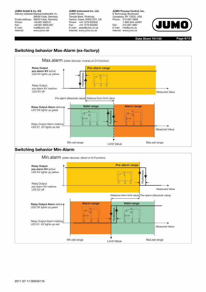
Switching behavior Max-Alarm (ex-factory)
Switching behavior Min-AlarmLimit Value
S
P
14 1615
Ö
3,15A
S
P
14 1615
Ö
3,15A
Min.set.range Max.set.range
Hys
tere
sis
Relay Output Alarm aktiveLED OK lights up green
Relay Output Alarm inaktiveLED K1, K2 lights up red
S
P
11 12 13
Ö
Max.alarm (older devices: inverse or O-Function)
Distance from limit value
Pre-alarm range
Measured Value
Measured Value
Alarm rangeValid range
Pre-alarm (Absolute value)
Hys
tere
sis
Relay Outputpre-alarm KV activeLED KV lights up yellow
Relay Outputpre-alarm KV inaktiveLED KV off
S
P
14 1615
Ö
3,15A
S
P
14 1615
Ö
3,15A
Hys
tere
sis
Hys
tere
sis
S
P
11 12 13
Ö
Min.alarm ( direct or S-Function)older devices:
Relay Outputpre-alarm KV activeLED KV lights up yellow
Relay OutputKV inaktive
LED KV offpre-alarm
Relay Output Alarm aktiveLED OK lights up green
Relay Output Alarm inaktiveLED K1, K2 lights up red
Pre-alarm range
Alarm range Valid range
Limit ValueMin.set.range Max.set.range
Measured Value
Measured Value
Distance from limit value Pre-alarm (Absolute value)
2011-07-11/00540116
Data Sheet 701150 Page 7/13
JUMO GmbH & Co. KGDelivery address:Mackenrodtstraße 14,
36039 Fulda, GermanyPostal address: 36035 Fulda, GermanyPhone: +49 661 6003-0Fax: +49 661 6003-607E-mail: [email protected]: www.jumo.net
JUMO Instrument Co. Ltd.JUMO HouseTemple Bank, RiverwayHarlow, Essex CM20 2DY, UKPhone: +44 1279 635533Fax: +44 1279 635262E-mail: [email protected]: www.jumo.co.uk
JUMO Process Control, Inc.8 Technology BoulevardCanastota, NY 13032, USAPhone: 315-697-5866
1-800-554-JUMOFax: 315-697-5867E-mail: [email protected]: www.jumo.us
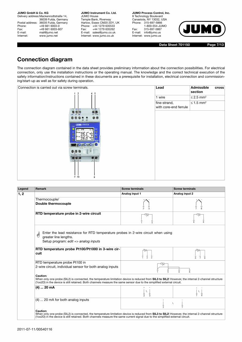
Connection diagramThe connection diagram contained in the data sheet provides preliminary information about the connection possibilities. For electricalconnection, only use the installation instructions or the operating manual. The knowledge and the correct technical execution of thesafety information/instructions contained in these documents are a prerequisite for installation, electrical connection and commission-ing/start-up as well as for safety during operation.
Connection is carried out via screw terminals. Lead Admissible crosssection
1 wire 2.5 mm2
fine-strand, with core-end ferrule
1.5 mm2
Legend Remark Screw terminals Screw terminals
1, 2 Analog input 1 Analog input 2
Thermocouple/Double thermocouple
RTD temperature probe in 2-wire circuit
RTD temperature probe Pt100/Pt1000 in 3-wire cir-cuit
RTD temperature probe Pt100 in2-wire circuit, individual sensor for both analog inputs
Caution:When only one probe (SIL2) is connected, the temperature limitation device is reduced from SIL3 to SIL2! However, the internal 2-channel structure (1oo2D) in the device is still retained. Both channels measure the same sensor due to the simplified external circuit.
(4) ... 20 mA
(4) ... 20 mA for both analog inputs
Caution:When only one probe (SIL2) is connected, the temperature limitation device is reduced from SIL3 to SIL2! However, the internal 2-channel structure (1oo2D) in the device is still retained. Both channels measure the same current signal due to the simplified external circuit.
+ –
2 3
+ –
7 8
�
1 3
�
6 8
A Enter the lead resistance for RTD temperature probes in 2-wire circuit when usinggreater line lengths.Setup program: edit => analog inputs
1 2 3
�
6 7 8
�
�
1 3 6 8
2 3
+ –
Ix
7 8
+ –
Ix
2
+ –
Ix
7
2011-07-11/00540116
Data Sheet 701150 Page 8/13
JUMO GmbH & Co. KGDelivery address:Mackenrodtstraße 14,
36039 Fulda, GermanyPostal address: 36035 Fulda, GermanyPhone: +49 661 6003-0Fax: +49 661 6003-607E-mail: [email protected]: www.jumo.net
JUMO Instrument Co. Ltd.JUMO HouseTemple Bank, RiverwayHarlow, Essex CM20 2DY, UKPhone: +44 1279 635533Fax: +44 1279 635262E-mail: [email protected]: www.jumo.co.uk
JUMO Process Control, Inc.8 Technology BoulevardCanastota, NY 13032, USAPhone: 315-697-5866
1-800-554-JUMOFax: 315-697-5867E-mail: [email protected]: www.jumo.us
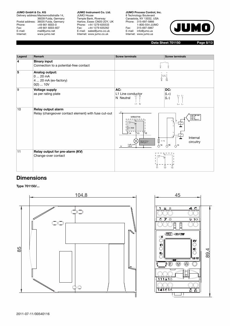
DimensionsType 701150/...
4 Binary inputConnection to a potential-free contact
5 Analog output: 0 ... 20 mA4 ... 20 mA (ex-factory)0(2) ... 10V
9 Voltage supply as per rating plate
AC:L1 Line conductorN Neutral
DC:(L+)(L-)
10 Relay output alarmRelay (changeover contact element) with fuse cut-out
11 Relay output for pre-alarm (KV)Change-over contact
Legend Remark Screw terminals Screw terminals
4 5
9 10
+–
Ix,Ux
L1 N
L1 N
L+ L-
L+ L-
Internalcircuitry
S
P
11 12 13
Ö
45
89 4,85
104 8,
2011-07-11/00540116
Data Sheet 701150 Page 9/13
JUMO GmbH & Co. KGDelivery address:Mackenrodtstraße 14,
36039 Fulda, GermanyPostal address: 36035 Fulda, GermanyPhone: +49 661 6003-0Fax: +49 661 6003-607E-mail: [email protected]: www.jumo.net
JUMO Instrument Co. Ltd.JUMO HouseTemple Bank, RiverwayHarlow, Essex CM20 2DY, UKPhone: +44 1279 635533Fax: +44 1279 635262E-mail: [email protected]: www.jumo.co.uk
JUMO Process Control, Inc.8 Technology BoulevardCanastota, NY 13032, USAPhone: 315-697-5866
1-800-554-JUMOFax: 315-697-5867E-mail: [email protected]: www.jumo.us
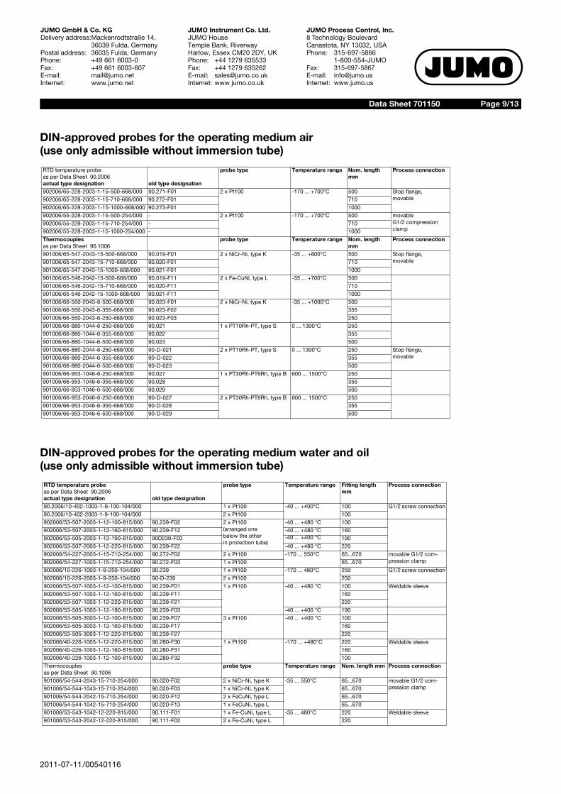
DIN-approved probes for the operating medium air (use only admissible without immersion tube)
DIN-approved probes for the operating medium water and oil (use only admissible without immersion tube)
RTD temperature probeas per Data Sheet 90.2006actual type designation old type designation
probe type Temperature range Nom. length mm
Process connection
902006/65-228-2003-1-15-500-668/000 90.271-F01 2 x Pt100 -170 ... +700°C 500 Stop flange,movable902006/65-228-2003-1-15-710-668/000 90.272-F01 710
902006/65-228-2003-1-15-1000-668/000 90.273-F01 1000902006/55-228-2003-1-15-500-254/000 - 2 x Pt100 -170 ... +700°C 500 movable
G1/2 compression clamp
902006/55-228-2003-1-15-710-254/000 - 710902006/55-228-2003-1-15-1000-254/000 - 1000Thermocouplesas per Data Sheet 90.1006
probe type Temperature range Nom. length mm
Process connection
901006/65-547-2043-15-500-668/000 90.019-F01 2 x NiCr-Ni, type K -35 ... +800°C 500 Stop flange,movable901006/65-547-2043-15-710-668/000 90.020-F01 710
901006/65-547-2043-15-1000-668/000 90.021-F01 1000901006/65-546-2042-15-500-668/000 90.019-F11 2 x Fe-CuNi, type L -35 ... +700°C 500901006/65-546-2042-15-710-668/000 90.020-F11 710901006/65-546-2042-15-1000-668/000 90.021-F11 1000901006/66-550-2043-6-500-668/000 90.023-F01 2 x NiCr-Ni, type K -35 ... +1000°C 500901006/66-550-2043-6-355-668/000 90.023-F02 355901006/66-550-2043-6-250-668/000 90.023-F03 250901006/66-880-1044-6-250-668/000 90,021 1 x PT10Rh-PT, type S 0 ... 1300°C 250901006/66-880-1044-6-355-668/000 90,022 355901006/66-880-1044-6-500-668/000 90,023 500901006/66-880-2044-6-250-668/000 90-D-021 2 x PT10Rh-PT, type S 0 ... 1300°C 250 Stop flange,
movable901006/66-880-2044-6-355-668/000 90-D-022 355901006/66-880-2044-6-500-668/000 90-D-023 500901006/66-953-1046-6-250-668/000 90,027 1 x PT30Rh-PT6Rh, type B 600 ... 1500°C 250901006/66-953-1046-6-355-668/000 90,028 355901006/66-953-1046-6-500-668/000 90,029 500901006/66-953-2046-6-250-668/000 90-D-027 2 x PT30Rh-PT6Rh, type B 600 ... 1500°C 250901006/66-953-2046-6-355-668/000 90-D-028 355901006/66-953-2046-6-500-668/000 90-D-029 500
RTD temperature probeas per Data Sheet 90.2006actual type designation old type designation
probe type Temperature range Fitting length mm
Process connection
90.2006/10-402-1003-1-9-100-104/000 1 x Pt100 -40 ... +400°C 100 G1/2 screw connection90.2006/10-402-2003-1-9-100-104/000 2 x Pt100 100902006/53-507-2003-1-12-100-815/000 90.239-F02 2 x Pt100
(arranged one below the other in protection tube)
-40 ... +480 °C 100902006/53-507-2003-1-12-160-815/000 90.239-F12 -40 ... +480 °C 160902006/53-505-2003-1-12-190-815/000 90D239-F03 -40 ... +400 °C 190902006/53-507-2003-1-12-220-815/000 90.239-F22 -40 ... +480 °C 220902006/54-227-2003-1-15-710-254/000 90.272-F02 2 x Pt100 -170 ... 550°C 65...670 movable G1/2 com-
pression clamp902006/54-227-1003-1-15-710-254/000 90.272-F03 1 x Pt100 65...670902006/10-226-1003-1-9-250-104/000 90.239 1 x Pt100 -170 ... 480°C 250 G1/2 screw connection902006/10-226-2003-1-9-250-104/000 90-D-239 2 x Pt100 250902006/53-507-1003-1-12-100-815/000 90.239-F01 1 x Pt100 -40 ... +480 °C 100 Weldable sleeve902006/53-507-1003-1-12-160-815/000 90.239-F11 160902006/53-507-1003-1-12-220-815/000 90.239-F21 220902006/53-505-1003-1-12-190-815/000 90.239-F03 -40 ... +400 °C 190902006/53-505-3003-1-12-100-815/000 90.239-F07 3 x Pt100 -40 ... +400 °C 100902006/53-505-3003-1-12-160-815/000 90.239-F17 160902006/53-505-3003-1-12-220-815/000 90.239-F27 220902006/40-226-1003-1-12-220-815/000 90.280-F30 1 x Pt100 -170 ... +480°C 220 Weldable sleeve902006/40-226-1003-1-12-160-815/000 90.280-F31 160902006/40-226-1003-1-12-100-815/000 90.280-F32 100Thermocouplesas per Data Sheet 90.1006
probe type Temperature range Nom. length mm Process connection
901006/54-544-2043-15-710-254/000 90.020-F02 2 x NiCr-Ni, type K -35 ... 550°C 65...670 movable G1/2 com-pression clamp901006/54-544-1043-15-710-254/000 90.020-F03 1 x NiCr-Ni, type K 65...670
901006/54-544-2042-15-710-254/000 90.020-F12 2 x FeCuNi, type L 65...670901006/54-544-1042-15-710-254/000 90.020-F13 1 x FeCuNi, type L 65...670901006/53-543-1042-12-220-815/000 90.111-F01 1 x Fe-CuNi, type L -35 ... 480°C 220 Weldable sleeve901006/53-543-2042-12-220-815/000 90.111-F02 2 x Fe-CuNi, type L 220
Page 10/13Data Sheet 701150
2011-07-11/00540116
JUMO GmbH & Co. KGDelivery address:Mackenrodtstraße 14,
36039 Fulda, GermanyPostal address: 36035 Fulda, GermanyPhone: +49 661 6003-0Fax: +49 661 6003-607E-mail: [email protected]: www.jumo.net
JUMO Instrument Co. Ltd.JUMO HouseTemple Bank, RiverwayHarlow, Essex CM20 2DY, UKPhone: +44 1279 635533Fax: +44 1279 635262E-mail: [email protected]: www.jumo.co.uk
JUMO Process Control, Inc.8 Technology BoulevardCanastota, NY 13032, USAPhone: 315-697-5866
1-800-554-JUMOFax: 315-697-5867E-mail: [email protected]: www.jumo.us
Safety control and regulating instrumentsSafety temperature monitors STW1
The safety temperature monitor is a device that is automatically reset when activated, once the sensor temperature has fallen below orrisen above the set limit value by an amount equal to the hysteresis. Possible settings: monitoring for limit value overrange or under-range.
Mode of operation:Minimum requirements: 2B, 2K, 2Padditionally met requirements: 2N, 2D
Safety temperature limiters STB1
The safety temperature limiter is a device that is permanently locked after response. Manual reset using the RESET key is possible once the probe temperature is gone below / has exceeded the limit value by the hystere-sis. Possible settings: monitoring for overrange or underrange.
Mode of operation:Minimum requirement: 2B, 2J, 2V, 2K, 2P and adjustable with special tooladditionally met requirements: 2N, 2F, 2D
1For more detailed explanation, see DIN EN 14 597.
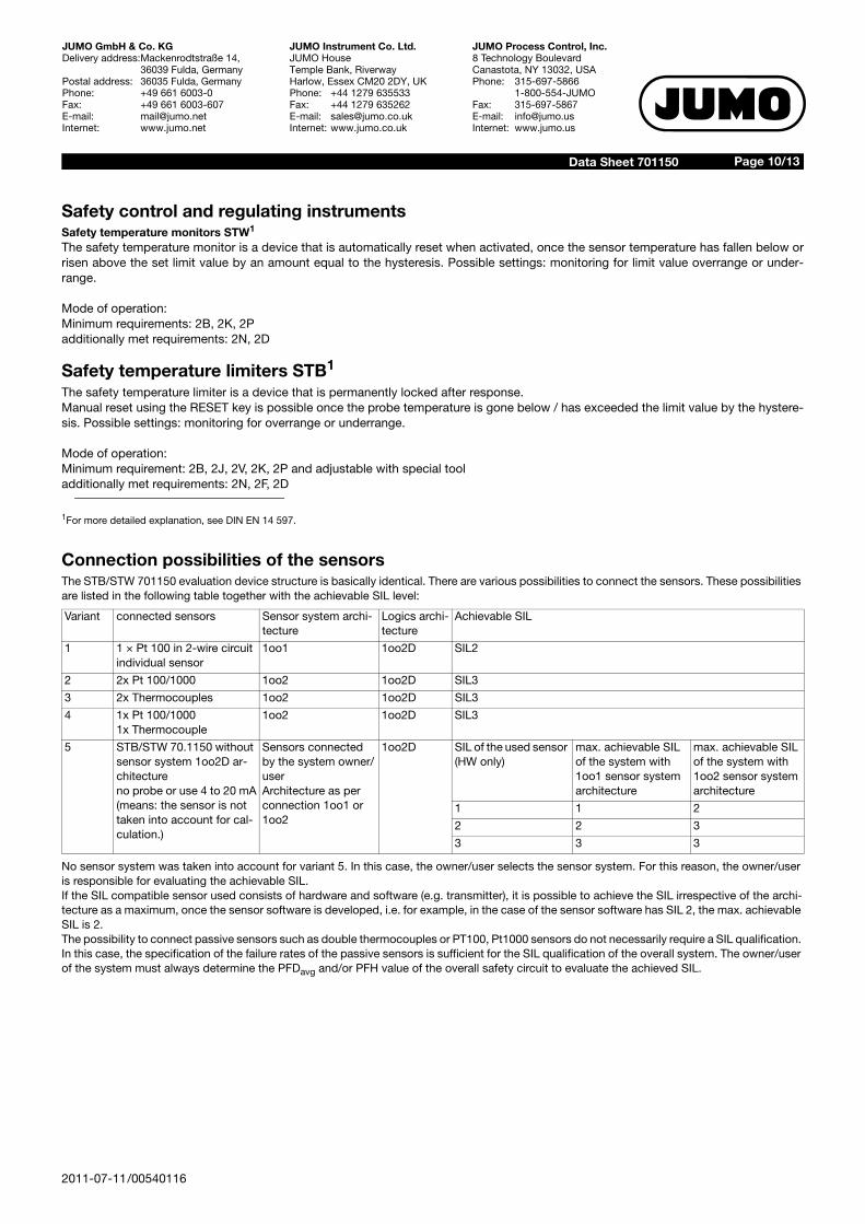
Connection possibilities of the sensorsThe STB/STW 701150 evaluation device structure is basically identical. There are various possibilities to connect the sensors. These possibilities are listed in the following table together with the achievable SIL level:
No sensor system was taken into account for variant 5. In this case, the owner/user selects the sensor system. For this reason, the owner/user is responsible for evaluating the achievable SIL. If the SIL compatible sensor used consists of hardware and software (e.g. transmitter), it is possible to achieve the SIL irrespective of the archi-tecture as a maximum, once the sensor software is developed, i.e. for example, in the case of the sensor software has SIL 2, the max. achievable SIL is 2.The possibility to connect passive sensors such as double thermocouples or PT100, Pt1000 sensors do not necessarily require a SIL qualification. In this case, the specification of the failure rates of the passive sensors is sufficient for the SIL qualification of the overall system. The owner/user of the system must always determine the PFDavg and/or PFH value of the overall safety circuit to evaluate the achieved SIL.
Variant connected sensors Sensor system archi-tecture
Logics archi-tecture
Achievable SIL
1 1 × Pt 100 in 2-wire circuitindividual sensor
1oo1 1oo2D SIL2
2 2x Pt 100/1000 1oo2 1oo2D SIL3
3 2x Thermocouples 1oo2 1oo2D SIL3
4 1x Pt 100/10001x Thermocouple
1oo2 1oo2D SIL3
5 STB/STW 70.1150 without sensor system 1oo2D ar-chitectureno probe or use 4 to 20 mA(means: the sensor is not taken into account for cal-culation.)
Sensors connected by the system owner/userArchitecture as per connection 1oo1 or 1oo2
1oo2D SIL of the used sensor (HW only)
max. achievable SIL of the system with 1oo1 sensor system architecture
max. achievable SIL of the system with 1oo2 sensor system architecture
1 1 2
2 2 3
3 3 3
Page 11/13Data Sheet 701150
2011-07-11/00540116
JUMO GmbH & Co. KGDelivery address:Mackenrodtstraße 14,
36039 Fulda, GermanyPostal address: 36035 Fulda, GermanyPhone: +49 661 6003-0Fax: +49 661 6003-607E-mail: [email protected]: www.jumo.net
JUMO Instrument Co. Ltd.JUMO HouseTemple Bank, RiverwayHarlow, Essex CM20 2DY, UKPhone: +44 1279 635533Fax: +44 1279 635262E-mail: [email protected]: www.jumo.co.uk
JUMO Process Control, Inc.8 Technology BoulevardCanastota, NY 13032, USAPhone: 315-697-5866
1-800-554-JUMOFax: 315-697-5867E-mail: [email protected]: www.jumo.us
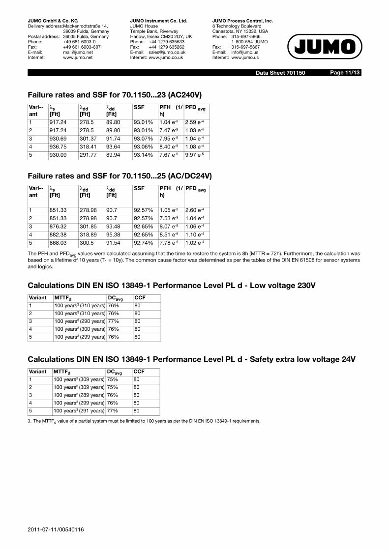
Failure rates and SSF for 70.1150...23 (AC240V)
Failure rates and SSF for 70.1150...25 (AC/DC24V)
The PFH and PFDavg values were calculated assuming that the time to restore the system is 8h (MTTR = 72h). Furthermore, the calculation was based on a lifetime of 10 years (T1 = 10y). The common cause factor was determined as per the tables of the DIN EN 61508 for sensor systems and logics.
Calculations DIN EN ISO 13849-1 Performance Level PL d - Low voltage 230V
Calculations DIN EN ISO 13849-1 Performance Level PL d - Safety extra low voltage 24V
3. The MTTFd value of a partial system must be limited to 100 years as per the DIN EN ISO 13849-1 requirements.
Vari--ant
s[Fit]
dd[Fit]
dd[Fit]
SSF PFH (1/h)
PFD avg
1 917.24 278.5 89.80 93.01% 1.04 e-8 2.59 e-4
2 917.24 278.5 89.80 93.01% 7.47 e-9 1.03 e-4
3 930.69 301.37 91.74 93.07% 7.95 e-9 1.04 e-4
4 936.75 318.41 93.64 93.06% 8.40 e-9 1.08 e-4
5 930.09 291.77 89.94 93.14% 7.67 e-9 9.97 e-5
Vari--ant
s[Fit]
dd[Fit]
dd[Fit]
SSF PFH (1/h)
PFD avg
1 851.33 278.98 90.7 92.57% 1.05 e-8 2.60 e-4
2 851.33 278.98 90.7 92.57% 7.53 e-9 1.04 e-4
3 876.32 301.85 93.48 92.65% 8.07 e-9 1.06 e-4
4 882.38 318.89 95.38 92.65% 8.51 e-9 1.10 e-4
5 868.03 300.5 91.54 92.74% 7.78 e-9 1.02 e-4
Variant MTTFd DCavg CCF
1 100 years3 (310 years) 76% 80
2 100 years3 (310 years) 76% 80
3 100 years3 (290 years) 77% 80
4 100 years3 (300 years) 76% 80
5 100 years3 (299 years) 76% 80
Variant MTTFd DCavg CCF
1 100 years3 (309 years) 75% 80
2 100 years3 (309 years) 75% 80
3 100 years3 (289 years) 76% 80
4 100 years3 (299 years) 76% 80
5 100 years3 (291 years) 77% 80
Page 12/13Data Sheet 701150
2011-07-11/00540116
JUMO GmbH & Co. KGDelivery address:Mackenrodtstraße 14,
36039 Fulda, GermanyPostal address: 36035 Fulda, GermanyPhone: +49 661 6003-0Fax: +49 661 6003-607E-mail: [email protected]: www.jumo.net
JUMO Instrument Co. Ltd.JUMO HouseTemple Bank, RiverwayHarlow, Essex CM20 2DY, UKPhone: +44 1279 635533Fax: +44 1279 635262E-mail: [email protected]: www.jumo.co.uk
JUMO Process Control, Inc.8 Technology BoulevardCanastota, NY 13032, USAPhone: 315-697-5866
1-800-554-JUMOFax: 315-697-5867E-mail: [email protected]: www.jumo.us
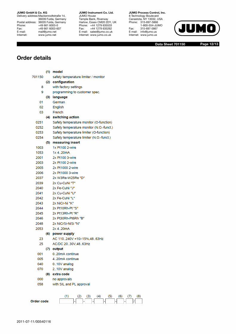
Order details
Page 13/13Data Sheet 701150
2011-07-11/00540116
JUMO GmbH & Co. KGDelivery address:Mackenrodtstraße 14,
36039 Fulda, GermanyPostal address: 36035 Fulda, GermanyPhone: +49 661 6003-0Fax: +49 661 6003-607E-mail: [email protected]: www.jumo.net
JUMO Instrument Co. Ltd.JUMO HouseTemple Bank, RiverwayHarlow, Essex CM20 2DY, UKPhone: +44 1279 635533Fax: +44 1279 635262E-mail: [email protected]: www.jumo.co.uk
JUMO Process Control, Inc.8 Technology BoulevardCanastota, NY 13032, USAPhone: 315-697-5866
1-800-554-JUMOFax: 315-697-5867E-mail: [email protected]: www.jumo.us
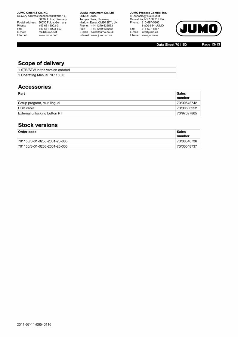
Scope of delivery1 STB/STW in the version ordered
1 Operating Manual 70.1150.0
AccessoriesPart Sales
number
Setup program, multilingual 70/00548742
USB cable 70/00506252
External unlocking button RT 70/97097865
Stock versionsOrder code Sales
number
701150/8-01-0253-2001-23-005 70/00548736
701150/8-01-0253-2001-25-005 70/00548737