Embed Size (px)
Citation preview

July 2017
Get the latest version of the User Guide at help.propelleraero.com
Getting started 5
How to get help 5
Glossary 5
Access your portal 8
Setting up a new portal 8
Granting Site access to new Site Users 8
Batch user management 9
Granting access to new Admin Users 10
Activating a user account 10
Customise your portal 11
Managing the appearance of your portal 11
Managing billing and viewing processing requests 12
Change your license 13
Change your billing email address 14
View your processing requests 14
Managing your user details 14
Navigating in the viewer 15
Turning on the Demo Sites 15
Exploring the different views 16
Toggle between views 17
Navigating in the Map View 17
Navigating in the Photo View 18
Using the Annotations Tab 19
Using the Layers Tab 21
propelleraero.com // page 2
Changing the Viewer settings 22
Creating a Site 23
Creating a new site 23
Adding a design surface to your new Site 23
Uploading data 24
Uploading drone survey data 24
Uploading source photos 24
Uploading photos to a dataset 25
Enter ground control point data 26
Guidelines for ground control point files 27
GCP rows and columns 27
Decimal places 27
Uploading data with an AeroPoint survey 28
Uploading data without ground control points 28
Upload status 29
Service Level Agreement 29
Uploading custom data 30
Design surface (DXF, DWG, OrthoTIFF) 30
Overlay (KMZ, KML, GeoJSON, CZML) 30
Downloading data 31
Where to download data 31
Coordinate Reference System and Projection of downloaded data 32
Downloads from the Layers Tab 32
Orthophoto (.JPG ) 33
DEM (.TIF ) 33
TIN (.DXF) Surface 3D Faces 34
propelleraero.com // page 3
Point Cloud (.LAZ) 34
3D Model (.OBJ ) 35
.TIF Orthomosaic 36
Custom .KML and .KMZ files 36
Making measurements 37
Annotations 37
Tools for creating Annotations 37
Editing and Deleting Annotations 38
Measurement Tools 38
Site Tools 39
Point Tools 39
Line Tools 39
Volume and Area Tools 40
Tools for exporting data 43
propelleraero.com // page 4
Getting started How to get help
You can access support from the following places:
■ help.propelleraero.com for the Knowledge Centre and the latest User Guide
■ Inside the Portal: go to Help > Send a Message (sends a message in the
browser app and copies [email protected])
■ [email protected] for questions you can’t answer from the above
Glossary
In this User Guide we refer to Licenses, Portals, Sites, Datasets, Data objects,
Annotations, Users, and Admin Users. Here’s an explanation of what these terms
mean to Propeller.
License
When you purchase access to the Propeller portal, your License specifies how many Sites (geographic locations) and Datasets (drone flights) you can add to your Portal as well as pricing information.
Portal Your portal is the website created for you at http://<your-portal-name>.prpellr.com
Site A Site is where your drone flight data is stored. One Site represents one geographic location with one or more drone flight Datasets.
propelleraero.com // page 5
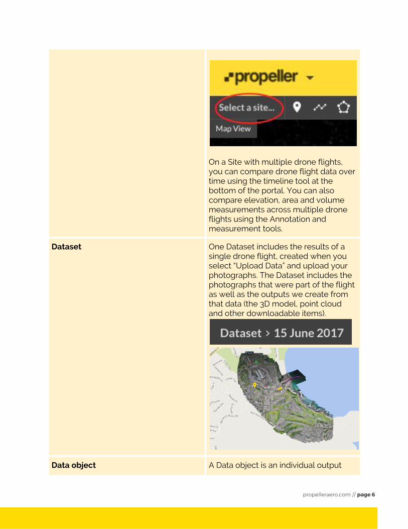
On a Site with multiple drone flights, you can compare drone flight data over time using the timeline tool at the bottom of the portal. You can also compare elevation, area and volume measurements across multiple drone flights using the Annotation and measurement tools.
Dataset
One Dataset includes the results of a single drone flight, created when you select “Upload Data” and upload your photographs. The Dataset includes the photographs that were part of the flight as well as the outputs we create from that data (the 3D model, point cloud and other downloadable items).
Data object A Data object is an individual output
propelleraero.com // page 6
belonging to a complete dataset. For example, it is one 3D model, point cloud or other downloadable item.
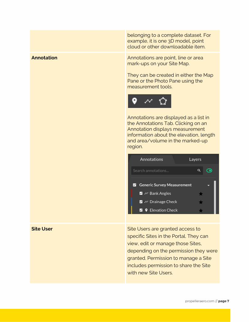
Annotation Annotations are point, line or area mark-ups on your Site Map. They can be created in either the Map Pane or the Photo Pane using the measurement tools.
Annotations are displayed as a list in the Annotations Tab. Clicking on an Annotation displays measurement information about the elevation, length and area/volume in the marked-up region.
Site User Site Users are granted access to
specific Sites in the Portal. They can
view, edit or manage those Sites,
depending on the permission they were
granted. Permission to manage a Site
includes permission to share the Site
with new Site Users.
propelleraero.com // page 7
Admin User Users with the ability to manage the
organisation’s portal are known as
“Admin Users”. These users can create
and manage all Sites, configure the
portal, and share Sites with new users.
Access your portal
Setting up a new portal
When you purchased a License, we collected the following details from you:
■ Organization name
■ Your preferred portal address
■ The email address of the first portal user
The email address you provide will be sent an activation link inviting them to create
a Propeller account to view the portal. (If the email address is already associated
with a Propeller account, the email they receive will contain a link to the portal, but
no activation link.)
After the email-address owner follows the activation link, Propeller will grant “Admin
User” access to this email address. “Admin Users” can configure the organization’s
portal, manage billing and create and manage all Sites in the portal.
Granting Site access to new Site Users
New Site Users can be added to a Site in Viewer 2.0 by navigating to the Site then clicking on the sharing button. Adding a user and selecting view, edit or manage
permissions will send them an activation email, inviting them to create an account
and password to log in to the Portal.
Ask the user to add [email protected] to their email safelist to ensure they
receive the email.
propelleraero.com // page 8
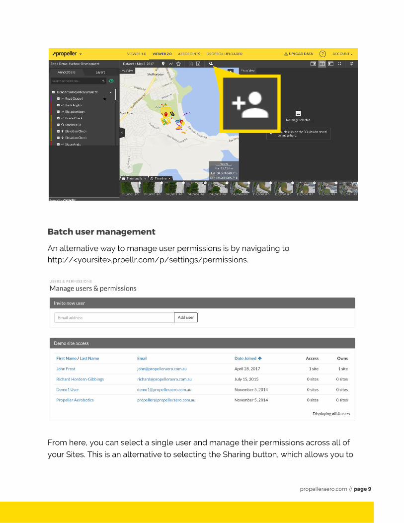
Batch user management
An alternative way to manage user permissions is by navigating to http://<yoursite>.prpellr.com/p/settings/permissions.
From here, you can select a single user and manage their permissions across all of
your Sites. This is an alternative to selecting the Sharing button, which allows you to
propelleraero.com // page 9
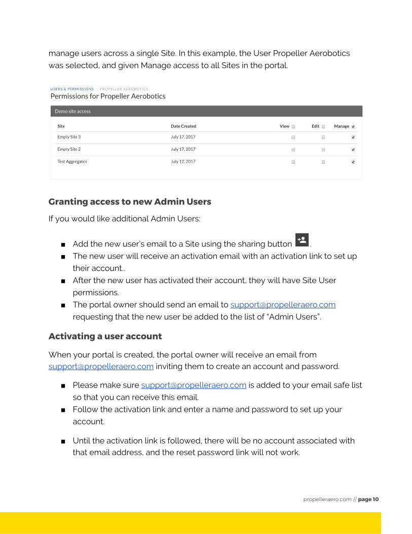
manage users across a single Site. In this example, the User Propeller Aerobotics
was selected, and given Manage access to all Sites in the portal.
Granting access to new Admin Users
If you would like additional Admin Users:
■ Add the new user’s email to a Site using the sharing button .
■ The new user will receive an activation email with an activation link to set up
their account..
■ After the new user has activated their account, they will have Site User
permissions.
■ The portal owner should send an email to [email protected]
requesting that the new user be added to the list of “Admin Users”.
Activating a user account
When your portal is created, the portal owner will receive an email from [email protected] inviting them to create an account and password.
■ Please make sure [email protected] is added to your email safe list
so that you can receive this email.
■ Follow the activation link and enter a name and password to set up your
account.
■ Until the activation link is followed, there will be no account associated with that email address, and the reset password link will not work.
propelleraero.com // page 10
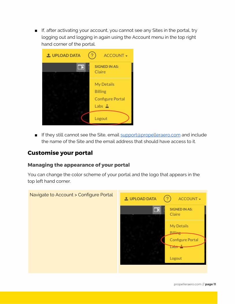
■ If, after activating your account, you cannot see any Sites in the portal, try
logging out and logging in again using the Account menu in the top right
hand corner of the portal.
■ If they still cannot see the Site, email [email protected] and include the name of the Site and the email address that should have access to it.
Customise your portal
Managing the appearance of your portal
You can change the color scheme of your portal and the logo that appears in the top left hand corner.
Navigate to Account > Configure Portal
propelleraero.com // page 11
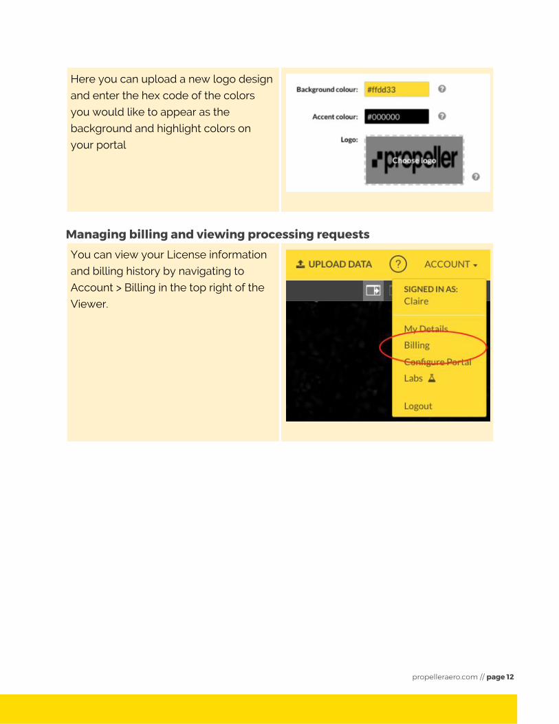
Here you can upload a new logo design
and enter the hex code of the colors
you would like to appear as the
background and highlight colors on
your portal
Managing billing and viewing processing requests
You can view your License information
and billing history by navigating to
Account > Billing in the top right of the
Viewer.
propelleraero.com // page 12
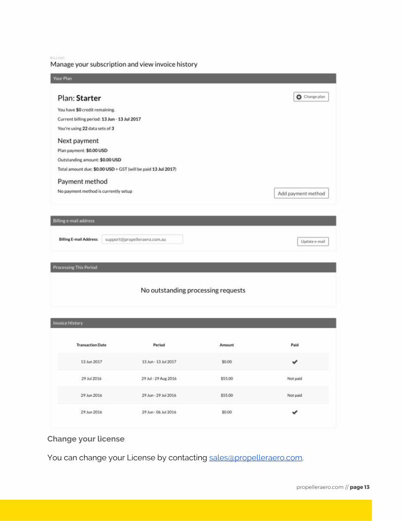
Change your license
You can change your License by contacting [email protected].
propelleraero.com // page 13
Change your billing email address
You can update your billing email address under Account > Billing.
View your processing requests
You can view the status of your recent processing requests in Account > Billing.
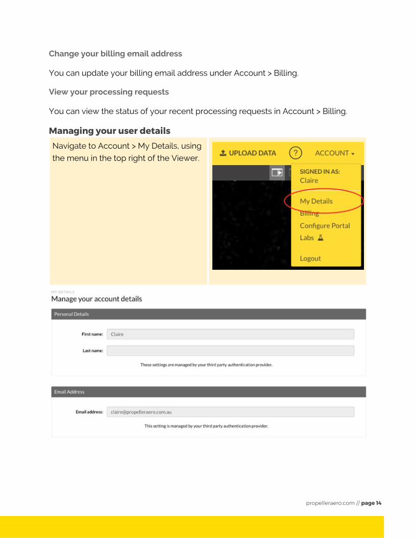
Managing your user details Navigate to Account > My Details, using
the menu in the top right of the Viewer.
propelleraero.com // page 14
If you signed in using Google to authenticate your email address, the option to
change your name and email address will be unavailable. You can change these
details if you log in using your email address and password.
Navigating in the viewer You can explore the viewer after selecting a Site. If you have not yet created a Site,
you can explore the Viewer using the Demo Sites.
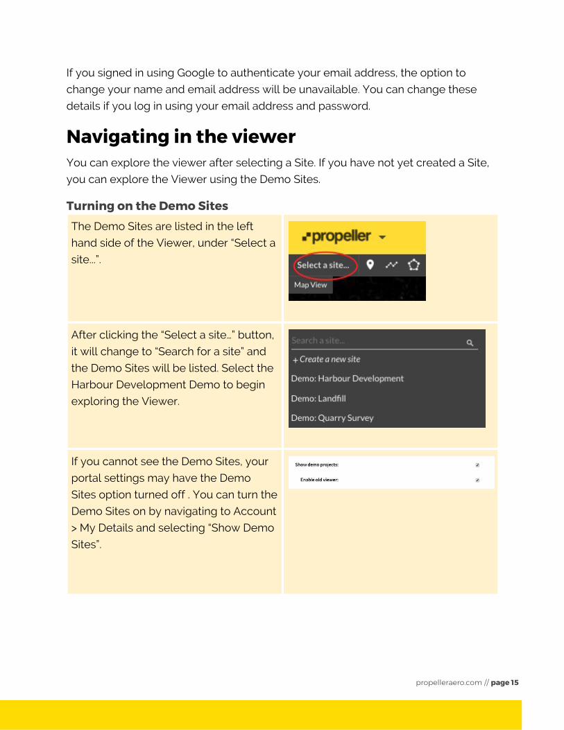
Turning on the Demo Sites The Demo Sites are listed in the left
hand side of the Viewer, under “Select a
site...”.
After clicking the “Select a site…” button,
it will change to “Search for a site” and
the Demo Sites will be listed. Select the
Harbour Development Demo to begin
exploring the Viewer.
If you cannot see the Demo Sites, your
portal settings may have the Demo
Sites option turned off . You can turn the
Demo Sites on by navigating to Account
> My Details and selecting “Show Demo
Sites”.
propelleraero.com // page 15
Exploring the different views
The Viewer has three different views:
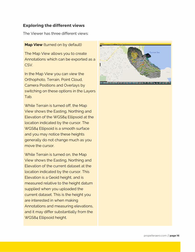
Map View (turned on by default)
The Map View allows you to create
Annotations which can be exported as a
CSV.
In the Map View you can view the
Orthophoto, Terrain, Point Cloud,
Camera Positions and Overlays by
switching on these options in the Layers
Tab.
While Terrain is turned off, the Map
View shows the Easting, Northing and
Elevation of the WGS84 Ellipsoid at the
location indicated by the cursor. The
WGS84 Ellipsoid is a smooth surface
and you may notice these heights
generally do not change much as you
move the cursor.
While Terrain is turned on, the Map
View shows the Easting, Northing and
Elevation of the current dataset at the
location indicated by the cursor. This
Elevation is a Geoid height, and is
measured relative to the height datum
supplied when you uploaded the
current dataset. This is the height you
are interested in when making
Annotations and measuring elevations,
and it may differ substantially from the
WGS84 Ellipsoid height.
propelleraero.com // page 16
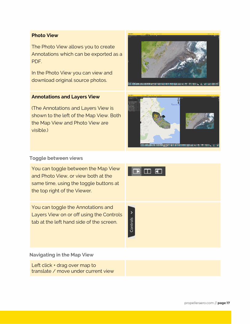
Photo View
The Photo View allows you to create
Annotations which can be exported as a
PDF.
In the Photo View you can view and
download original source photos.
Annotations and Layers View
(The Annotations and Layers View is
shown to the left of the Map View. Both
the Map View and Photo View are
visible.)
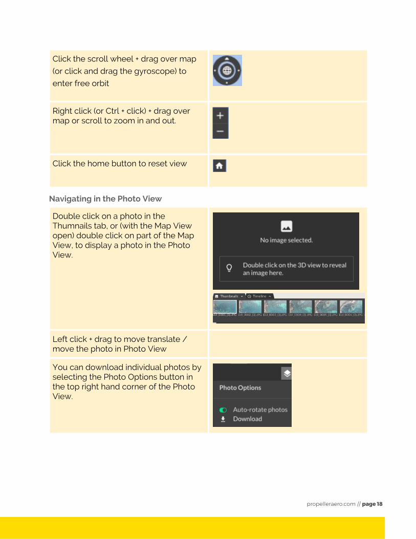
Toggle between views
You can toggle between the Map View
and Photo View, or view both at the
same time, using the toggle buttons at
the top right of the Viewer.
You can toggle the Annotations and
Layers View on or off using the Controls
tab at the left hand side of the screen.
Navigating in the Map View
Left click + drag over map totranslate / move under current view
propelleraero.com // page 17
Click the scroll wheel + drag over map
(or click and drag the gyroscope) to
enter free orbit
Right click (or Ctrl + click) + drag over map or scroll to zoom in and out.
Click the home button to reset view
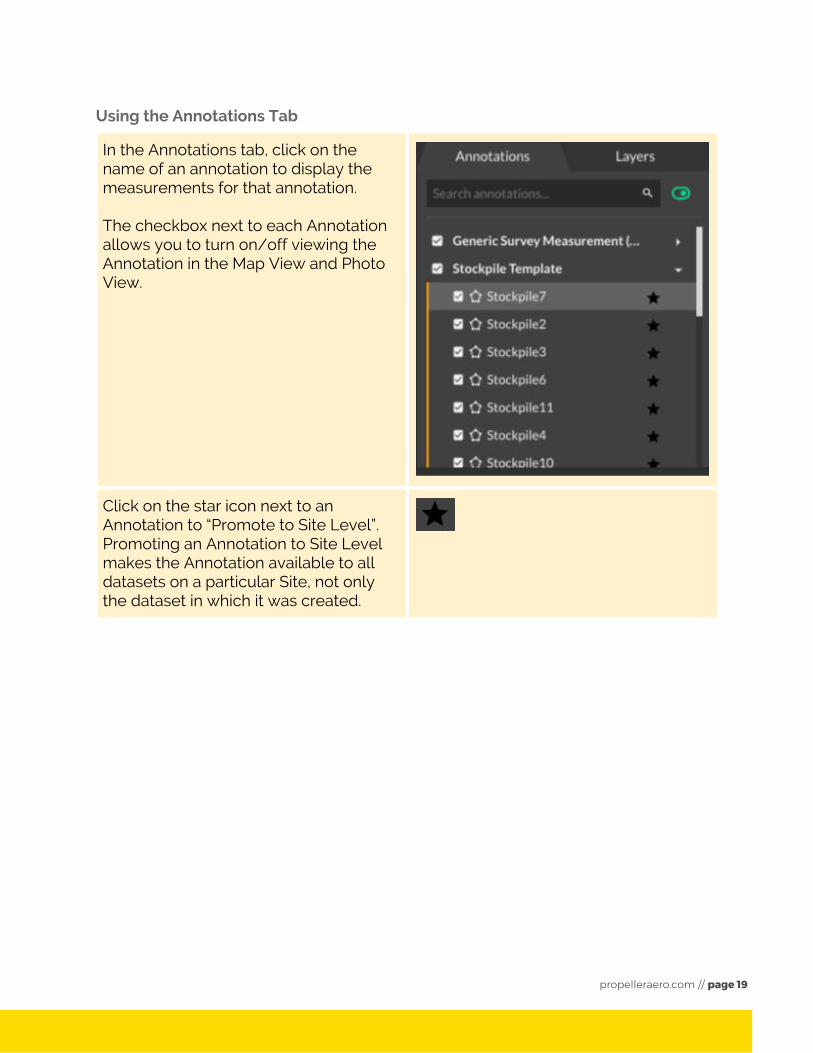
Navigating in the Photo View
Double click on a photo in the Thumnails tab, or (with the Map View open) double click on part of the Map View, to display a photo in the Photo View.
Left click + drag to move translate / move the photo in Photo View
You can download individual photos by selecting the Photo Options button in the top right hand corner of the Photo View.
propelleraero.com // page 18
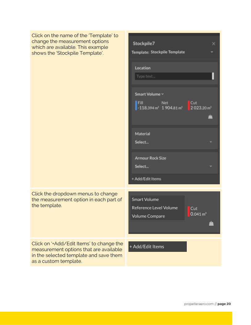
Using the Annotations Tab
In the Annotations tab, click on the name of an annotation to display the measurements for that annotation. The checkbox next to each Annotation allows you to turn on/off viewing the Annotation in the Map View and Photo View.
Click on the star icon next to an Annotation to “Promote to Site Level”. Promoting an Annotation to Site Level makes the Annotation available to all datasets on a particular Site, not only the dataset in which it was created.
propelleraero.com // page 19
Click on the name of the ‘Template’ to change the measurement options which are available. This example shows the ‘Stockpile Template’.
Click the dropdown menus to change the measurement option in each part of the template.
Click on ‘+Add/Edit Items’ to change the measurement options that are available in the selected template and save them as a custom template.
propelleraero.com // page 20
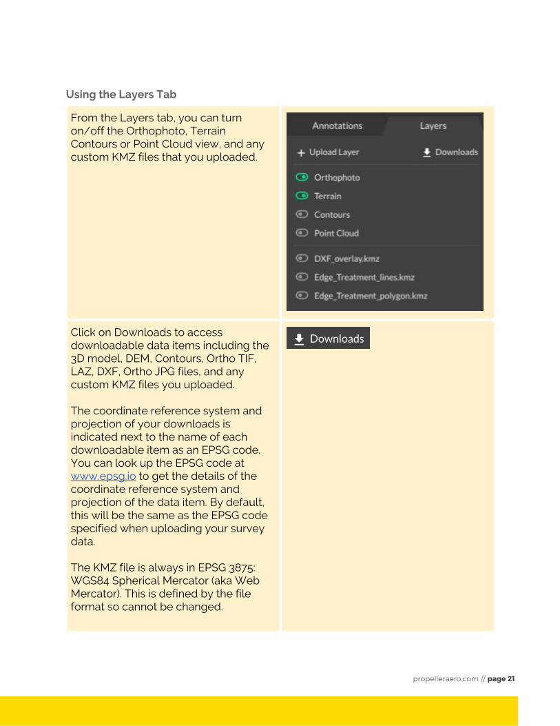
Using the Layers Tab
From the Layers tab, you can turn on/off the Orthophoto, Terrain Contours or Point Cloud view, and any custom KMZ files that you uploaded.
Click on Downloads to access downloadable data items including the 3D model, DEM, Contours, Ortho TIF, LAZ, DXF, Ortho JPG files, and any custom KMZ files you uploaded. The coordinate reference system and projection of your downloads is indicated next to the name of each downloadable item as an EPSG code. You can look up the EPSG code at www.epsg.io to get the details of the coordinate reference system and projection of the data item. By default, this will be the same as the EPSG code specified when uploading your survey data. The KMZ file is always in EPSG 3875: WGS84 Spherical Mercator (aka Web Mercator). This is defined by the file format so cannot be changed.
propelleraero.com // page 21
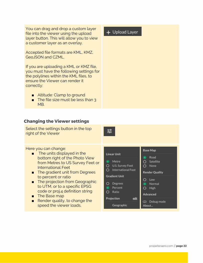
You can drag and drop a custom layer file into the viewer using the upload layer button. This will allow you to view a customer layer as an overlay. Accepted file formats are KML, KMZ, GeoJSON and CZML. If you are uploading a KML or KMZ file, you must have the following settings for the polylines within the KML files, to ensure the Viewer can render it correctly:
■ Altitude: Clamp to ground ■ The file size must be less than 3
MB.
Changing the Viewer settings Select the settings button in the top right of the Viewer
Here you can change: ■ The units displayed in the
bottom right of the Photo View from Metres to US Survey Feet or International Feet
■ The gradient unit from Degrees to percent or ratio
■ The projection from Geographic to UTM, or to a specific EPSG code or proj.4 definition string
■ The Base map ■ Render quality, to change the
speed the viewer loads.
propelleraero.com // page 22
Creating a Site
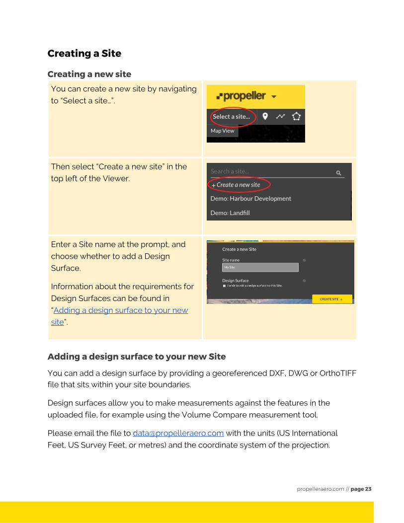
Creating a new site You can create a new site by navigating
to “Select a site…”.
Then select “Create a new site” in the
top left of the Viewer.
Enter a Site name at the prompt, and
choose whether to add a Design
Surface.
Information about the requirements for
Design Surfaces can be found in
“ Adding a design surface to your new
site ”.
Adding a design surface to your new Site
You can add a design surface by providing a georeferenced DXF, DWG or OrthoTIFF file that sits within your site boundaries.
Design surfaces allow you to make measurements against the features in the
uploaded file, for example using the Volume Compare measurement tool.
Please email the file to [email protected] with the units (US International
Feet, US Survey Feet, or metres) and the coordinate system of the projection.
propelleraero.com // page 23
Uploading data Uploading drone survey data
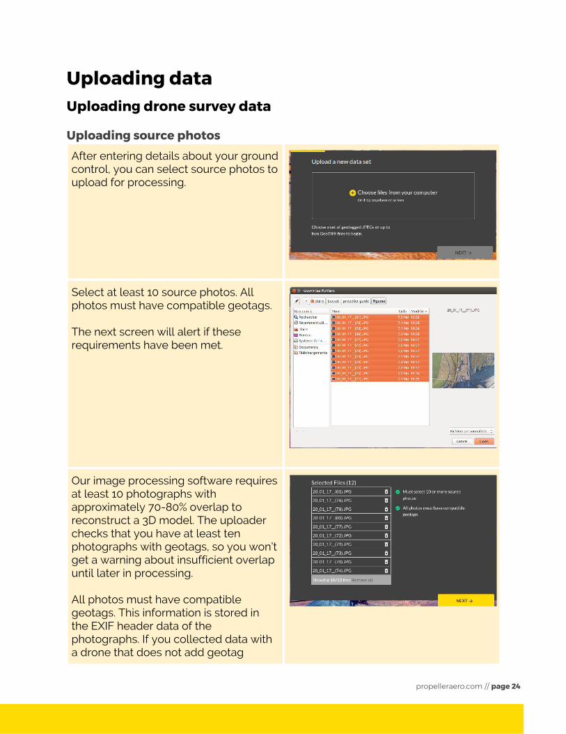
Uploading source photos After entering details about your ground control, you can select source photos to upload for processing.
Select at least 10 source photos. All photos must have compatible geotags. The next screen will alert if these requirements have been met.
Our image processing software requires at least 10 photographs with approximately 70-80% overlap to reconstruct a 3D model. The uploader checks that you have at least ten photographs with geotags, so you won’t get a warning about insufficient overlap until later in processing. All photos must have compatible geotags. This information is stored in the EXIF header data of the photographs. If you collected data with a drone that does not add geotag
propelleraero.com // page 24
information to the photographs, you may need to use software like exiftool to add the geotag information back into the photographs, before you can upload data.
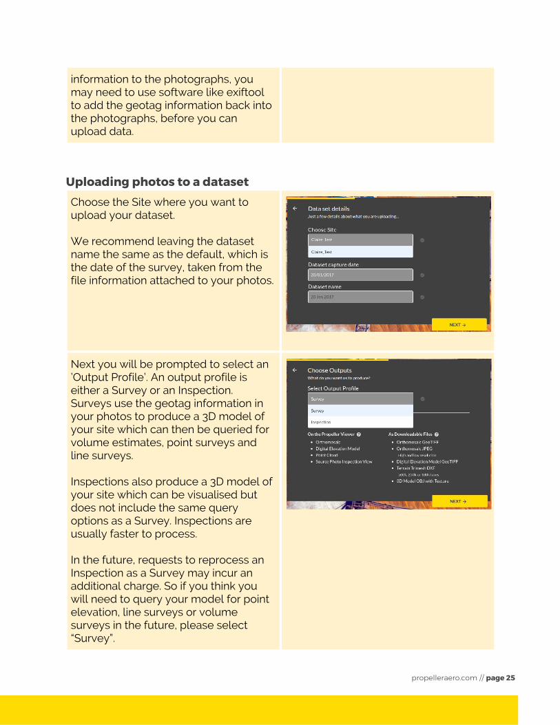
Uploading photos to a dataset Choose the Site where you want to upload your dataset. We recommend leaving the dataset name the same as the default, which is the date of the survey, taken from the file information attached to your photos.
Next you will be prompted to select an ’Output Profile’. An output profile is either a Survey or an Inspection. Surveys use the geotag information in your photos to produce a 3D model of your site which can then be queried for volume estimates, point surveys and line surveys. Inspections also produce a 3D model of your site which can be visualised but does not include the same query options as a Survey. Inspections are usually faster to process. In the future, requests to reprocess an Inspection as a Survey may incur an additional charge. So if you think you will need to query your model for point elevation, line surveys or volume surveys in the future, please select “Survey”.
propelleraero.com // page 25
Enter ground control point data
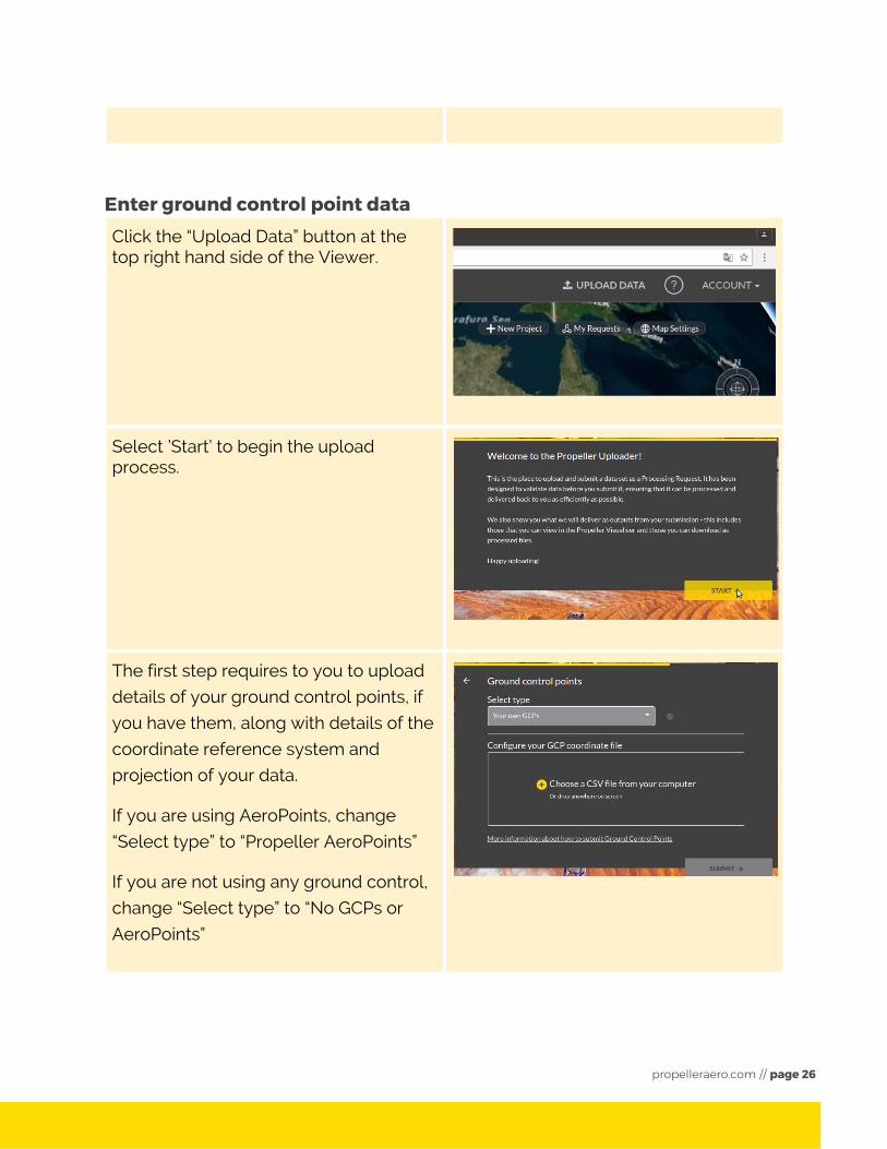
Click the “Upload Data” button at the top right hand side of the Viewer.
Select ’Start’ to begin the upload process.
The first step requires to you to upload
details of your ground control points, if
you have them, along with details of the
coordinate reference system and
projection of your data.
If you are using AeroPoints, change
“Select type” to “Propeller AeroPoints”
If you are not using any ground control,
change “Select type” to “No GCPs or
AeroPoints”
propelleraero.com // page 26
Guidelines for ground control point files
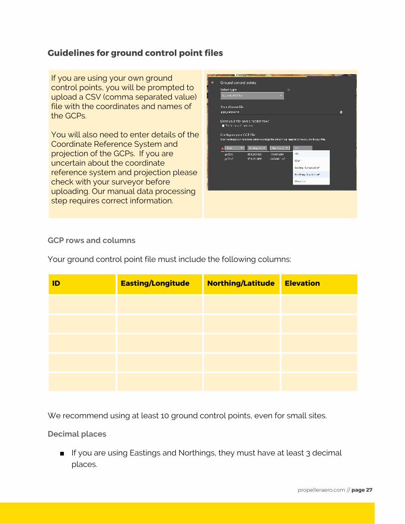
If you are using your own ground control points, you will be prompted to upload a CSV (comma separated value) file with the coordinates and names of the GCPs. You will also need to enter details of the Coordinate Reference System and projection of the GCPs. If you are uncertain about the coordinate reference system and projection please check with your surveyor before uploading. Our manual data processing step requires correct information.
GCP rows and columns
Your ground control point file must include the following columns:
ID Easting/Longitude Northing/Latitude Elevation
We recommend using at least 10 ground control points, even for small sites.
Decimal places
■ If you are using Eastings and Northings, they must have at least 3 decimal places.
propelleraero.com // page 27
■ If you are using Longitude and Latitude, they must be formatted as decimal
degrees with at least 8 decimal places.
Uploading data with an AeroPoint survey
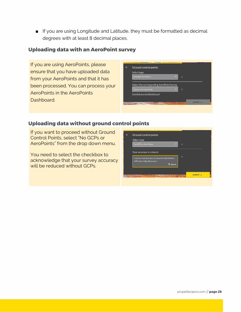
If you are using AeroPoints, please
ensure that you have uploaded data
from your AeroPoints and that it has
been processed. You can process your
AeroPoints in the AeroPoints
Dashboard.
Uploading data without ground control points
If you want to proceed without Ground Control Points, select ”No GCPs or AeroPoints” from the drop down menu. You need to select the checkbox to acknowledge that your survey accuracy will be reduced without GCPs.
propelleraero.com // page 28
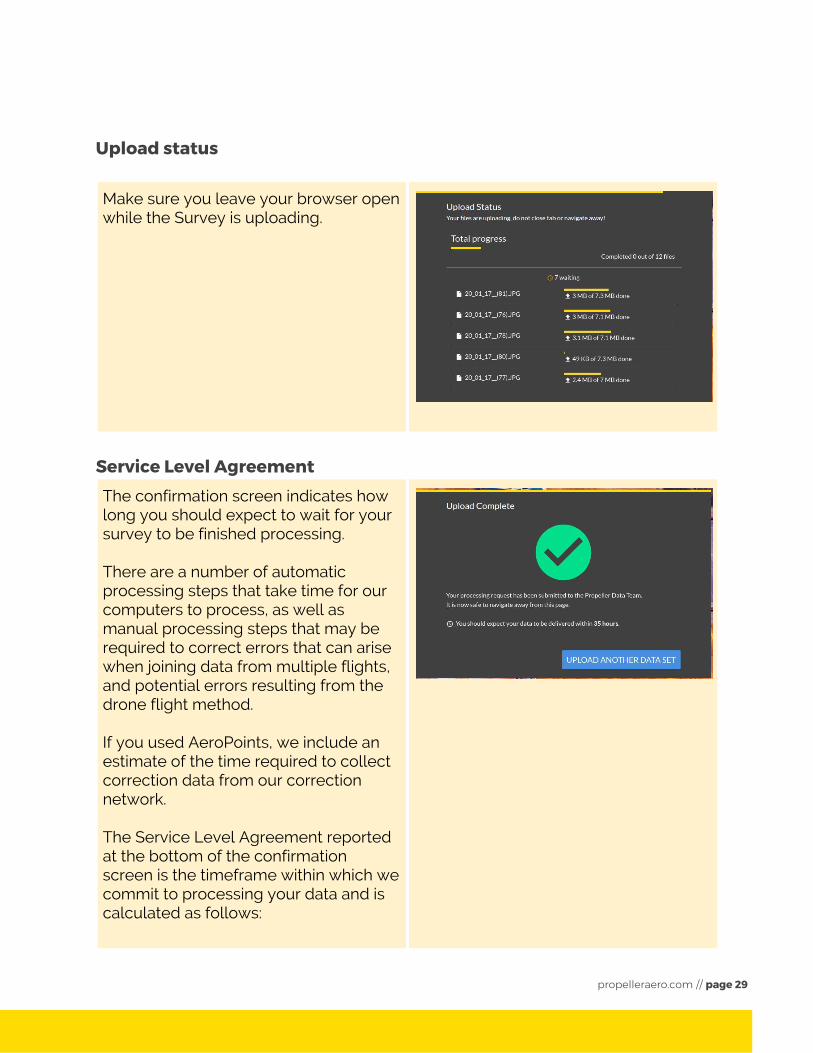
Upload status
Make sure you leave your browser open while the Survey is uploading.
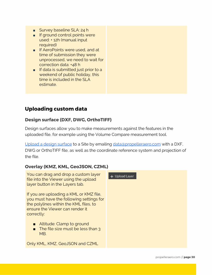
Service Level Agreement
The confirmation screen indicates how long you should expect to wait for your survey to be finished processing. There are a number of automatic processing steps that take time for our computers to process, as well as manual processing steps that may be required to correct errors that can arise when joining data from multiple flights, and potential errors resulting from the drone flight method. If you used AeroPoints, we include an estimate of the time required to collect correction data from our correction network. The Service Level Agreement reported at the bottom of the confirmation screen is the timeframe within which we commit to processing your data and is calculated as follows:
propelleraero.com // page 29
■ Survey baseline SLA: 24 h ■ If ground control points were
used: + 12h (manual input required)
■ If AeroPoints were used, and at time of submission they were unprocessed, we need to wait for correction data: +48 h
■ If data is submitted just prior to a weekend of public holiday, this time is included in the SLA estimate.
Uploading custom data
Design surface (DXF, DWG, OrthoTIFF)
Design surfaces allow you to make measurements against the features in the uploaded file, for example using the Volume Compare measurement tool.
Upload a design surface to a Site by emailing [email protected] with a DXF,
DWG or OrthoTIFF file, as well as the coordinate reference system and projection of
the file.
Overlay (KMZ, KML, GeoJSON, CZML) You can drag and drop a custom layer file into the Viewer using the upload layer button in the Layers tab. If you are uploading a KML or KMZ file, you must have the following settings for the polylines within the KML files, to ensure the Viewer can render it correctly:
■ Altitude: Clamp to ground ■ The file size must be less than 3
MB. Only KML, KMZ, GeoJSON and CZML
propelleraero.com // page 30
files can be accepted.
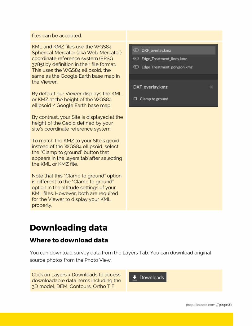
KML and KMZ files use the WGS84 Spherical Mercator (aka Web Mercator) coordinate reference system (EPSG 3785) by definition in their file format. This uses the WGS84 ellipsoid, the same as the Google Earth base map in the Viewer. By default our Viewer displays the KML or KMZ at the height of the WGS84 ellipsoid / Google Earth base map. By contrast, your Site is displayed at the height of the Geoid defined by your site’s coordinate reference system. To match the KMZ to your SIte’s geoid, instead of the WGS84 ellipsoid, select the “Clamp to ground” button that appears in the layers tab after selecting the KML or KMZ file. Note that this “Clamp to ground” option is different to the “Clamp to ground” option in the altitude settings of your KML files. However, both are required for the Viewer to display your KML properly.
Downloading data Where to download data
You can download survey data from the Layers Tab. You can download original
source photos from the Photo View.
Click on Layers > Downloads to access downloadable data items including the 3D model, DEM, Contours, Ortho TIF,
propelleraero.com // page 31
LAZ, DXF, Ortho JPG files, and any custom KMZ files you uploaded.
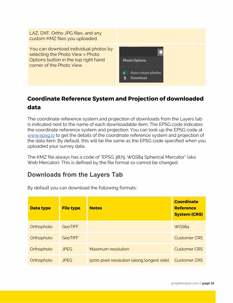
You can download individual photos by selecting the Photo View > Photo Options button in the top right hand corner of the Photo View.
Coordinate Reference System and Projection of downloaded data
The coordinate reference system and projection of downloads from the Layers tab is indicated next to the name of each downloadable item. The EPSG code indicates the coordinate reference system and projection. You can look up the EPSG code at www.epsg.io to get the details of the coordinate reference system and projection of the data item. By default, this will be the same as the EPSG code specified when you uploaded your survey data. The KMZ file always has a code of “EPSG 3875: WGS84 Spherical Mercator” (aka Web Mercator). This is defined by the file format so cannot be changed.
Downloads from the Layers Tab
By default you can download the following formats:
Data type File type Notes Coordinate Reference System (CRS)
Orthophoto GeoTIFF WGS84
Orthophoto GeoTIFF Customer CRS
Orthophoto JPEG Maximum resolution Customer CRS
Orthophoto JPEG 5000 pixel resolution (along longest side) Customer CRS
propelleraero.com // page 32
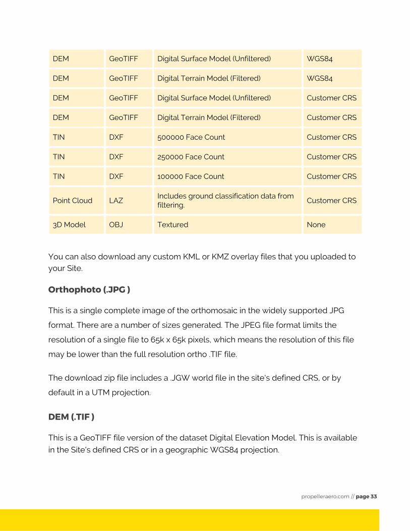
DEM GeoTIFF Digital Surface Model (Unfiltered) WGS84
DEM GeoTIFF Digital Terrain Model (Filtered) WGS84
DEM GeoTIFF Digital Surface Model (Unfiltered) Customer CRS
DEM GeoTIFF Digital Terrain Model (Filtered) Customer CRS
TIN DXF 500000 Face Count Customer CRS
TIN DXF 250000 Face Count Customer CRS
TIN DXF 100000 Face Count Customer CRS
Point Cloud LAZ Includes ground classification data from filtering.
Customer CRS
3D Model OBJ Textured None
You can also download any custom KML or KMZ overlay files that you uploaded to your Site.
Orthophoto (.JPG )
This is a single complete image of the orthomosaic in the widely supported JPG
format. There are a number of sizes generated. The JPEG file format limits the
resolution of a single file to 65k x 65k pixels, which means the resolution of this file
may be lower than the full resolution ortho .TIF file.
The download zip file includes a .JGW world file in the site's defined CRS, or by
default in a UTM projection.
DEM (.TIF )
This is a GeoTIFF file version of the dataset Digital Elevation Model. This is available
in the Site's defined CRS or in a geographic WGS84 projection.
propelleraero.com // page 33
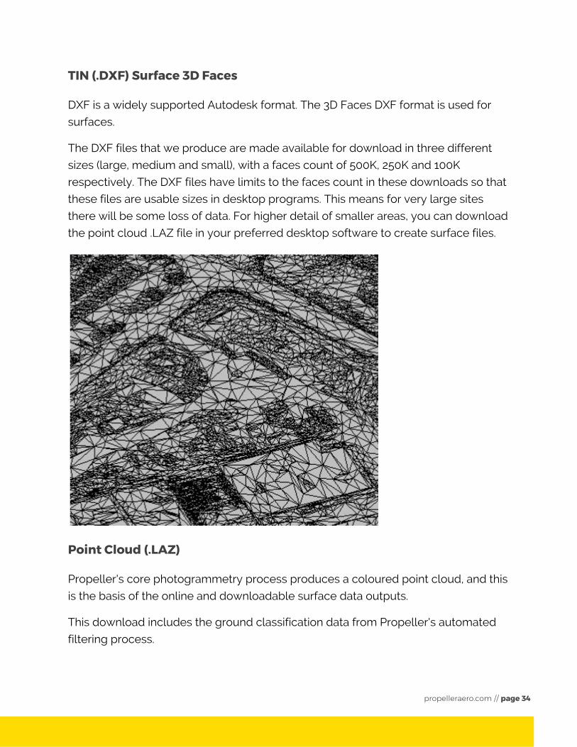
TIN (.DXF) Surface 3D Faces
DXF is a widely supported Autodesk format. The 3D Faces DXF format is used for
surfaces.
The DXF files that we produce are made available for download in three different
sizes (large, medium and small), with a faces count of 500K, 250K and 100K
respectively. The DXF files have limits to the faces count in these downloads so that
these files are usable sizes in desktop programs. This means for very large sites
there will be some loss of data. For higher detail of smaller areas, you can download
the point cloud .LAZ file in your preferred desktop software to create surface files.
Point Cloud (.LAZ)
Propeller's core photogrammetry process produces a coloured point cloud, and this
is the basis of the online and downloadable surface data outputs.
This download includes the ground classification data from Propeller's automated
filtering process.
propelleraero.com // page 34
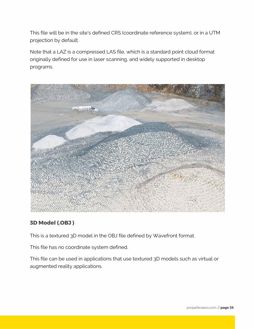
This file will be in the site's defined CRS (coordinate reference system), or in a UTM
projection by default.
Note that a LAZ is a compressed LAS file, which is a standard point cloud format
originally defined for use in laser scanning, and widely supported in desktop
programs.
3D Model (.OBJ )
This is a textured 3D model in the OBJ file defined by Wavefront format.
This file has no coordinate system defined.
This file can be used in applications that use textured 3D models such as virtual or
augmented reality applications.
propelleraero.com // page 35
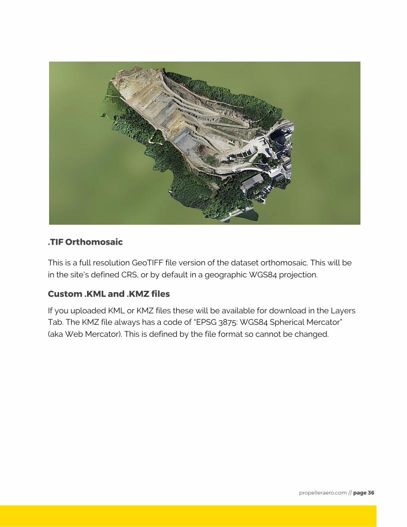
.TIF Orthomosaic
This is a full resolution GeoTIFF file version of the dataset orthomosaic. This will be
in the site's defined CRS, or by default in a geographic WGS84 projection.
Custom .KML and .KMZ files
If you uploaded KML or KMZ files these will be available for download in the Layers Tab. The KMZ file always has a code of “EPSG 3875: WGS84 Spherical Mercator”
(aka Web Mercator). This is defined by the file format so cannot be changed.
propelleraero.com // page 36
Making measurements The first step in making measurements is to create an Annotation using one of the
three Annotations tools - point, line and polygon. After making an Annotation, you
can select it from the list to view the different measurement tools available for that
type of Annotation. The measurement tools are clickable and allow you to visualize
the data and results of your measurements in the Map View.
If you create your Annotations in the Map View, you can download them later as a
CSV. If you create Annotations in the Photo View, you can download them later as a
PDF.
Annotations
There are three types of Annotations - point, line and polygon. Each type of
Annotation provides different types of Measurement Tools, which allow you to
display data and data visualizations on your Site.
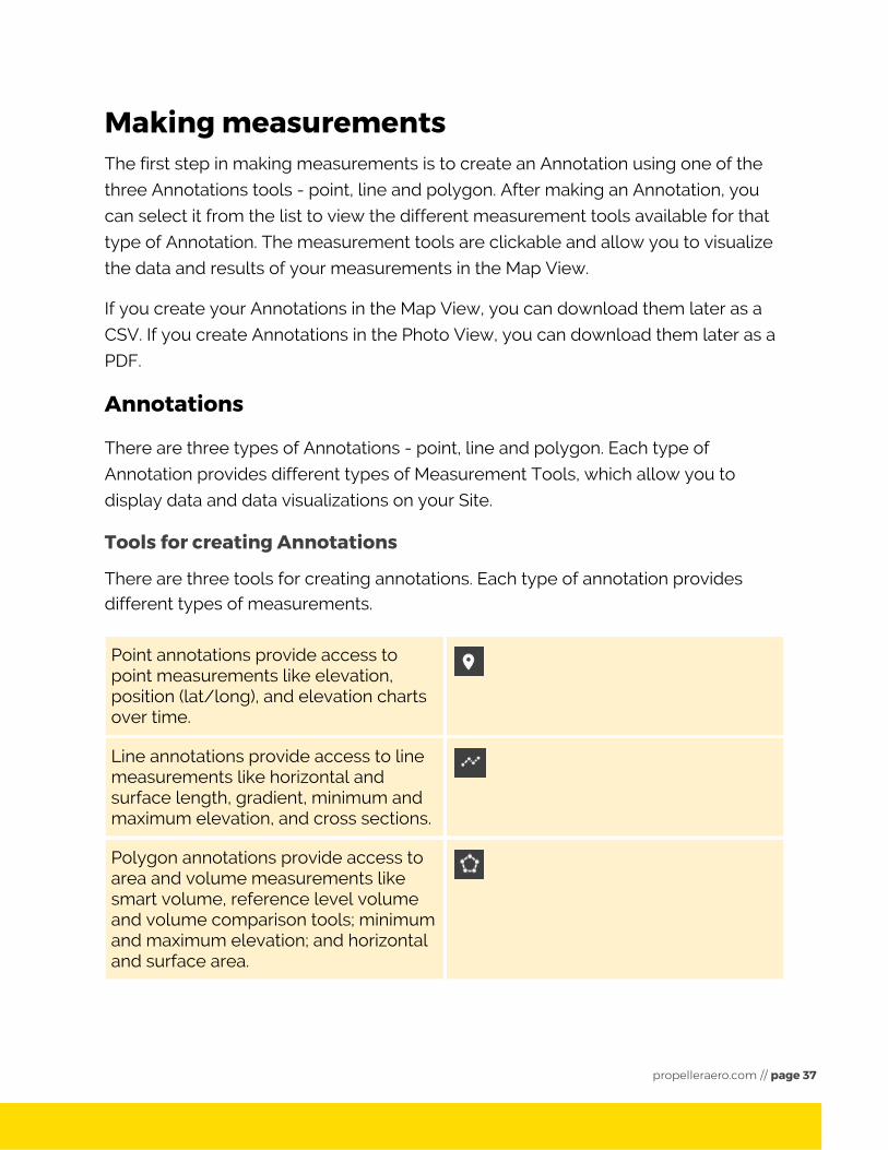
Tools for creating Annotations
There are three tools for creating annotations. Each type of annotation provides different types of measurements.
Point annotations provide access to point measurements like elevation, position (lat/long), and elevation charts over time.
Line annotations provide access to line measurements like horizontal and surface length, gradient, minimum and maximum elevation, and cross sections.
Polygon annotations provide access to area and volume measurements like smart volume, reference level volume and volume comparison tools; minimum and maximum elevation; and horizontal and surface area.
propelleraero.com // page 37
Editing and Deleting Annotations
To edit an Annotation, select it from the
list, and click the pencil icon which
appears next to its name in the Map
View.
To delete an Annotation, select it from
the list, and click the bin icon from the
list or the Map View
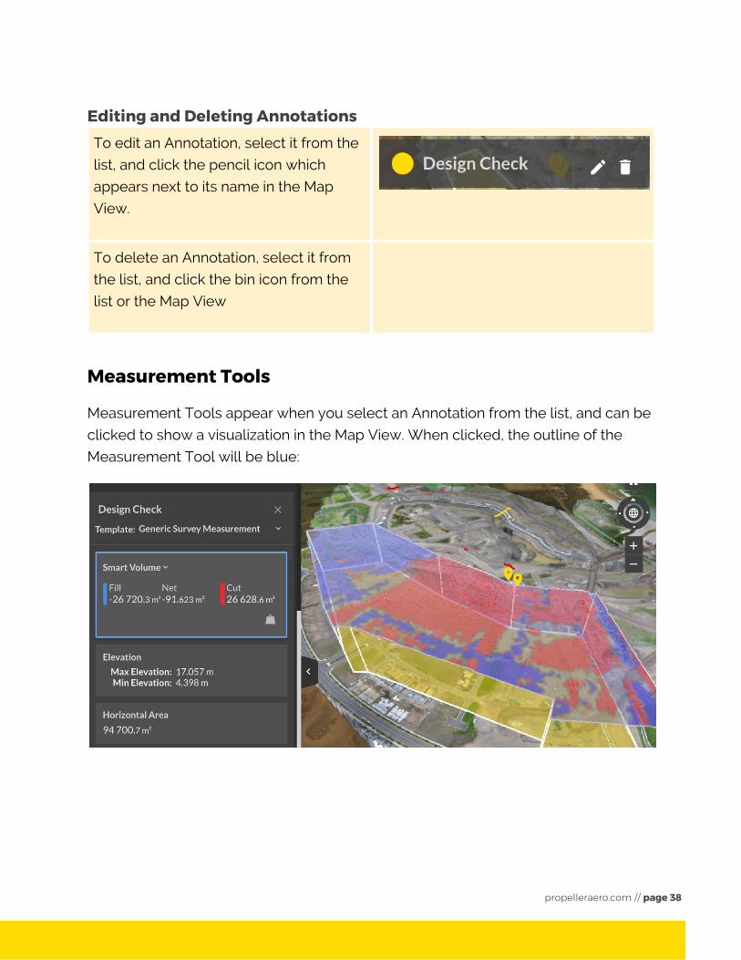
Measurement Tools
Measurement Tools appear when you select an Annotation from the list, and can be
clicked to show a visualization in the Map View. When clicked, the outline of the
Measurement Tool will be blue:
propelleraero.com // page 38
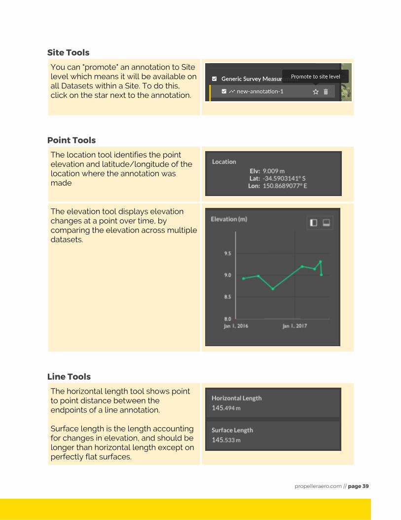
Site Tools You can "promote" an annotation to Site level which means it will be available on all Datasets within a Site. To do this, click on the star next to the annotation.
Point Tools The location tool identifies the point elevation and latitude/longitude of the location where the annotation was made
The elevation tool displays elevation changes at a point over time, by comparing the elevation across multiple datasets.
Line Tools The horizontal length tool shows point to point distance between the endpoints of a line annotation. Surface length is the length accounting for changes in elevation, and should be longer than horizontal length except on perfectly flat surfaces.
propelleraero.com // page 39
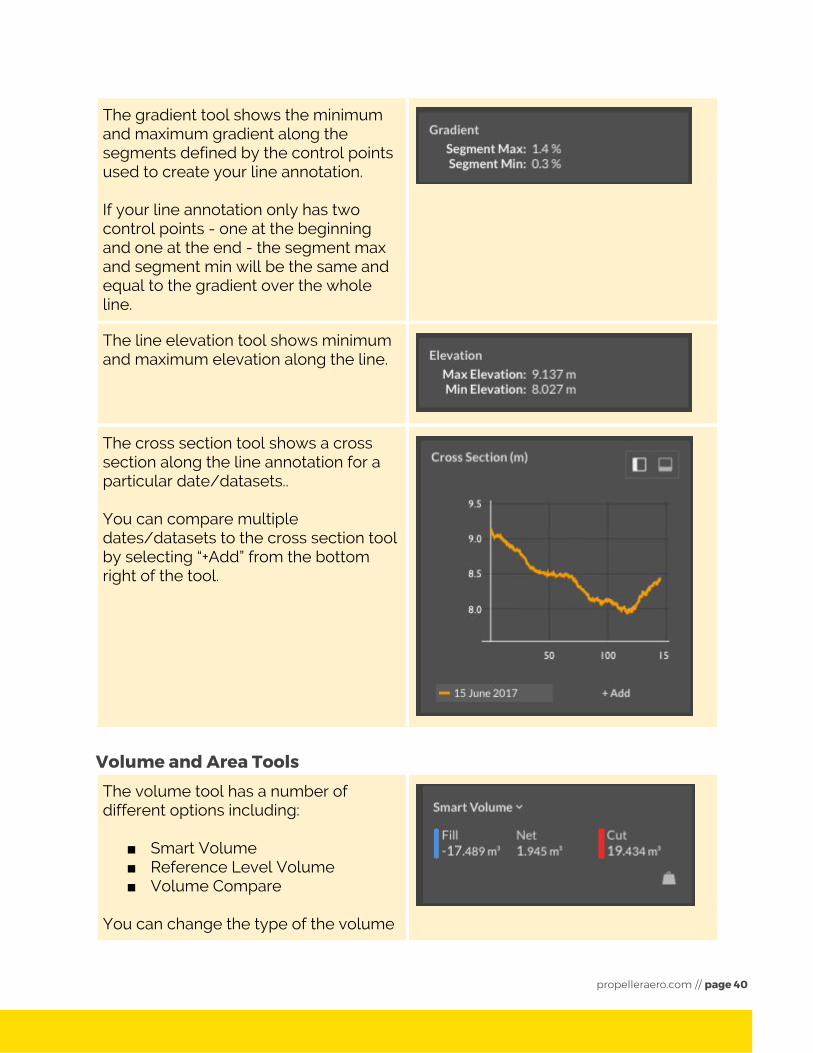
The gradient tool shows the minimum and maximum gradient along the segments defined by the control points used to create your line annotation. If your line annotation only has two control points - one at the beginning and one at the end - the segment max and segment min will be the same and equal to the gradient over the whole line.
The line elevation tool shows minimum and maximum elevation along the line.
The cross section tool shows a cross section along the line annotation for a particular date/datasets.. You can compare multiple dates/datasets to the cross section tool by selecting “+Add” from the bottom right of the tool.
Volume and Area Tools
The volume tool has a number of different options including:
■ Smart Volume ■ Reference Level Volume ■ Volume Compare
You can change the type of the volume
propelleraero.com // page 40
measurement tool by selecting the drop down menu next to the name of the volume tool. You can change the units from metres to feet by selecting the weight symbol in the bottom right of the tool.
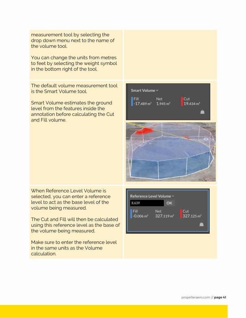
The default volume measurement tool is the Smart Volume tool. Smart Volume estimates the ground level from the features inside the annotation before calculating the Cut and Fill volume.
When Reference Level Volume is selected, you can enter a reference level to act as the base level of the volume being measured. The Cut and Fill will then be calculated using this reference level as the base of the volume being measured. Make sure to enter the reference level in the same units as the Volume calculation.
propelleraero.com // page 41
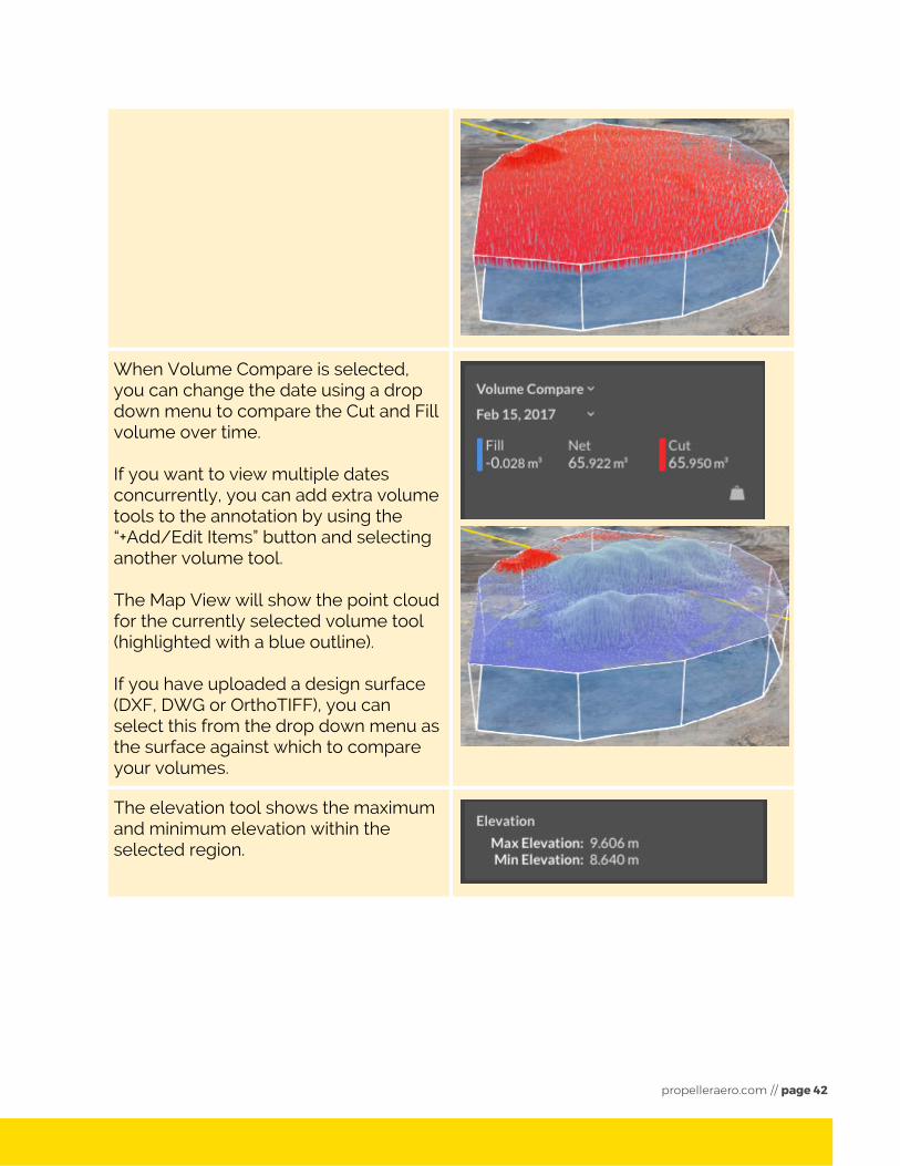
When Volume Compare is selected, you can change the date using a drop down menu to compare the Cut and Fill volume over time. If you want to view multiple dates concurrently, you can add extra volume tools to the annotation by using the “+Add/Edit Items” button and selecting another volume tool. The Map View will show the point cloud for the currently selected volume tool (highlighted with a blue outline). If you have uploaded a design surface (DXF, DWG or OrthoTIFF), you can select this from the drop down menu as the surface against which to compare your volumes.
The elevation tool shows the maximum and minimum elevation within the selected region.
propelleraero.com // page 42
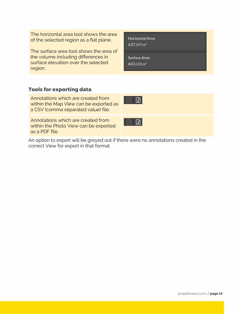
The horizontal area tool shows the area of the selected region as a flat plane. The surface area tool shows the area of the volume including differences in surface elevation over the selected region.
Tools for exporting data Annotations which are created from within the Map View can be exported as a CSV (comma separated value) file.
Annotations which are created from within the Photo View can be exported as a PDF file.
An option to export will be greyed out if there were no annotations created in the correct View for export in that format.
propelleraero.com // page 43