Embed Size (px)
Citation preview
JOINTINDUSTRY
STANDARD
Handling, Packing,
Shipping and Use of
Moisture/Reflow
Sensitive Surface
Mount Devices
IPC/JEDEC J-STD-033BOctober 2005
Supersedes IPC/JEDEC J-STD-033AJuly 2002
Notice JEDEC and IPC Standards and Publications are designed to serve the publicinterest through eliminating misunderstandings between manufacturers andpurchasers, facilitating interchangeability and improvement of products,and assisting the purchaser in selecting and obtaining with minimum delaythe proper product for his particular need. Existence of such Standards andPublications shall not in any respect preclude any member or nonmemberof JEDEC or IPC from manufacturing or selling products not conformingto such Standards and Publications, nor shall the existence of such Standardsand Publications preclude their voluntary use by those other than JEDECand IPC members, whether the standard is to be used either domesticallyor internationally.
Recommended Standards and Publications are adopted by JEDEC andIPC without regard to whether their adoption may involve patents on articles,materials, or processes. By such action, JEDEC and IPC do not assume anyliability to any patent owner, nor do they assume any obligation whateverto parties adopting the Recommended Standard or Publication. Users are alsowholly responsible for protecting themselves against all claims of liabilitiesfor patent infringement.
The material in this joint standard was developed by the JEDEC JC-14.1Committee on Reliability Test Methods for Packaged Devices and the IPCPlastic Chip Carrier Cracking Task Group (B-10a)
For Technical Information Contact:
JEDEC Solid State
Technology Association
2500 Wilson BoulevardArlington, VA 22201Phone (703) 907-7500Fax (703) 907-7583
IPC
3000 Lakeside DriveSuite 309SBannockburn, Illinois60015-1219Tel (847) 615-7100Fax (847) 615-7105
Please use the Standard Improvement Form shown at the end of thisdocument.
©Copyright 2005. JEDEC Solid State Technology Association, Arlington, Virginia, and IPC, Bannockburn, Illinois. All rights reserved underboth international and Pan-American copyright conventions. Any copying, scanning or other reproduction of these materials without the priorwritten consent of the copyright holder is strictly prohibited and constitutes infringement under the Copyright Law of the United States.
IPC/JEDEC J-STD-033B
Handling, Packing,
Shipping and Use of
Moisture/Reflow
Sensitive Surface
Mount Devices
A joint standard developed by the JEDEC JC-14.1 Committee onReliability Test Methods for Packaged Devices and the B-10a PlasticChip Carrier Cracking Task Group of IPC
Users of this standard are encouraged to participate in thedevelopment of future revisions.
Contact:
JEDEC
2500 Wilson Boulevard
Arlington, VA 22201
Phone (703) 907-7500
Fax (703) 907-7583
IPC
3000 Lakeside Drive, Suite 309S
Bannockburn, Illinois
60015-1219
Tel (847) 615-7100
Fax (847) 615-7105
Supersedes:IPC/JEDEC J-STD-033A -
July 2002IPC/JEDEC J-STD-033 -
April 1999JEDEC JEP124IPC-SM-786A - January 1995IPC-SM-786 - December 1990
ASSOCIATION CONNECTINGELECTRONICS INDUSTRIES ®

This Page Intentionally Left Blank
Table of Contents
1 FOREWORD ............................................................. 1
1.1 Purpose ................................................................. 1
1.2 Scope .................................................................... 1
1.2.1 Packages ............................................................... 1
1.3 Assembly Processes ............................................. 1
1.3.1 Mass Reflow ........................................................ 1
1.3.2 Localized Heating ................................................ 1
1.3.3 Socketed Components ......................................... 1
1.3.4 Point-to-Point Soldering ...................................... 1
1.4 Reliability ............................................................. 2
1.5 Terms and Definitions ......................................... 2
1.5.1 Active Desiccant .................................................. 2
1.5.2 Bar Code Label .................................................... 2
1.5.3 Bulk Reflow ......................................................... 2
1.5.4 Carrier .................................................................. 2
1.5.5 Desiccant .............................................................. 2
1.5.6 Floor Life ............................................................. 2
1.5.7 Humidity Indicator Card (HIC) ........................... 2
1.5.8 Manufacturer’s Exposure Time (MET) ............... 2
1.5.9 Moisture Barrier Bag (MBB) .............................. 2
1.5.10 Rework ................................................................. 2
1.5.11 Shelf Life ............................................................. 2
1.5.12 SMD ..................................................................... 2
1.5.13 Solder Reflow ...................................................... 2
1.5.14 Water Vapor Transmission Rate (WVTR) .......... 2
2 APPLICABLE DOCUMENTS ................................... 3
2.1 American Society for Testing and Materials(ASTM) ................................................................ 3
2.2 Electronic Industries Alliance (EIA, JEDEC) .... 3
2.3 IPC Standards ...................................................... 3
2.4 Joint Industry Standards ...................................... 3
2.5 Department of Defense ........................................ 3
3 DRY PACKING .......................................................... 3
3.1 Requirements ....................................................... 3
3.2 Drying of SMD Packages and CarrierMaterials Before Being Sealed in MBBs ........... 4
3.2.1 Drying Requirements - Levels 2a - 5a ............... 4
3.2.2 Drying Requirements - Carrier Materials ........... 4
3.2.3 Drying Requirements - Other .............................. 4
3.2.4 Excess Time Between Bake and Bag ................. 4
3.3 Dry Pack .............................................................. 4
3.3.1 Description ........................................................... 4
3.3.2 Materials ............................................................... 4
3.3.3 Labels ................................................................... 6
3.3.4 Moisture Barrier Bag Sealing ............................. 6
3.3.5 Shelf Life ............................................................. 6
4 DRYING ..................................................................... 7
4.1 Post Exposure to Factory Ambient ..................... 7
4.1.1 Any Duration Exposure ....................................... 7
4.1.2 Short Duration Exposure ..................................... 7
4.2 General Considerations for Baking ..................... 8
4.2.1 High Temperature Carriers .................................. 8
4.2.2 Low Temperature Carriers ................................... 8
4.2.3 Paper and Plastic Container Items ...................... 8
4.2.4 Bakeout Times ..................................................... 9
4.2.5 ESD Protection .................................................... 9
4.2.6 Reuse of Carriers ................................................. 9
4.2.7 Solderability Limitations ..................................... 9
5 USE ......................................................................... 10
5.1 Incoming Bag Inspection ................................... 10
5.1.1 Upon Receipt ..................................................... 10
5.1.2 Component Inspection ....................................... 10
5.2 Floor Life ........................................................... 10
5.3 Safe Storage ....................................................... 10
5.3.1 Dry Pack ............................................................ 10
5.3.2 Shelf Life ........................................................... 10
5.3.3 Dry Atmosphere Cabinet ................................... 10
5.4 Reflow ................................................................ 11
5.4.1 Opened MBB ..................................................... 11
5.4.2 Reflow Temperature Extremes .......................... 11
5.4.3 Additional Thermal Profile Parameters ............. 11
5.4.4 Multiple Reflow Passes ..................................... 11
5.4.5 Maximum Reflow Passes .................................. 11
5.5 Drying Indicators ............................................... 11
5.5.1 Excess Humidity in the Dry Pack ..................... 11
5.5.2 Floor Life or Ambient Temperature/Humidity Exceeded ........................................... 12
5.5.3 Level 6 SMD Packages ..................................... 12
6 BOARD REWORK .................................................. 12
6.1 Component Removal, Rework and Remount ... 12
6.1.1 Removal for Failure Analysis ........................... 12
6.1.2 Removal and Remount ...................................... 12
6.2 Baking of Populated Boards ............................. 12
7 DERATING DUE TO FACTORYENVIRONMENTAL CONDITIONS .......................... 12
October 2005 IPC/JEDEC J-STD-033B
v
Appendix A Test Method for Humidity IndicatorCard used with ElectronicComponent Packaging ........................ 14
Appendix B Derivation of Bake Tables .................. 15
Figures
Figure 3-1 Typical Dry Pack Configuration for Moisture-Sensitive SMD Packages in Shipping Tubes ..... 4
Figure 3-2 Example Humidity Indicator Card ....................... 5
Figure 3-3 Moisture-Sensitive Identification Label(Example) ............................................................ 6
Figure 3-4 Moisture-Sensitive Caution Label (Example) ...... 7
Figure A-1 Photo of Testing Apparatus ............................... 14
Tables
Table 3-1 Dry Packing Requirements ................................. 3
Table 3-2 Typical HIC Spot Compliance ............................. 6
Table 4-1 Reference Conditions for Drying Mounted orUnmounted SMD Packages ................................ 8
Table 4-2 Default Baking Times Used Prior to Dry-Packthat were Exposed to Conditions ≥60% RH(Supplier Bake: ‘‘MET’’ = 24 h) ........................... 9
Table 4-3 Resetting or Pausing the ‘‘Floor Life’’ Clock atUser Site ............................................................. 9
Table 5-1 Moisture Classification Level and Floor Life ..... 10
Table 7-1 Recommended Equivalent Total Floor Life(days) @ 20°C, 25°C & 30°C, 35°C For ICswith Novolac, Biphenyl and MultifunctionalEpoxies .............................................................. 13
IPC/JEDEC J-STD-033B October 2005
vi
Handling, Packing, Shipping and Use of Moisture/Reflow Sensitive Surface Mount Devices
1 FOREWORD
The advent of surface mount devices (SMDs) introduced a new class of quality and reliability concerns regarding packagedamage ‘‘cracks and delamination’’ from the solder reflow process. This document describes the standardized levels of floorlife exposure for moisture/reflow-sensitive SMD packages along with the handling, packing and shipping requirements nec-essary to avoid moisture/reflow-related failures. Companion documents J-STD-020 and JEP113 define the classification pro-cedure and the labeling requirements, respectively.
Moisture from atmospheric humidity enters permeable packaging materials by diffusion. Assembly processes used to solderSMD packages to printed circuit boards (PCBs) expose the entire package body to temperatures higher than 200°C. Duringsolder reflow, the combination of rapid moisture expansion, materials mismatch, and material interface degradation can resultin package cracking and/or delamination of critical interfaces within the package.
The solder reflow processes of concern are convection, convection/IR, infrared (IR), vapor phase (VPR) and hot air reworktools. The use of assembly processes that immerse the component body in molten solder are not recommended for mostSMD packages.
1.1 Purpose The purpose of this document is to provide SMD manufacturers and users with standardized methods forhandling, packing, shipping, and use of moisture/reflow sensitive SMD packages that have been classified to the levelsdefined in J-STD-020. These methods are provided to avoid damage from moisture absorption and exposure to solder reflowtemperatures that can result in yield and reliability degradation. By using these procedures, safe and damage-free reflow canbe achieved, with the dry packing process, providing a minimum shelf life capability in sealed dry-bags of 12 months fromthe seal date.
1.2 Scope
1.2.1 Packages
1.2.1.1 Nonhermetic This standard applies to all nonhermetic SMD packages subjected to bulk solder reflow processesduring PCB assembly, including plastic encapsulated packages and all other packages made with moisture-permeable poly-meric materials (epoxies, silicones, etc.) that are exposed to the ambient air.
1.2.1.2 Hermetic Hermetic SMD packages are not moisture sensitive and do not require moisture precautionary handling.
1.3 Assembly Processes
1.3.1 Mass Reflow This standard applies to bulk solder reflow assembly by convection, convection/IR, infrared (IR), andvapor phase (VPR) processes. It does not apply to bulk solder reflow processes that immerse the component bodies in mol-ten solder (e.g., wave soldering bottom mounted components). Such processes are not allowed for many SMDs and are notcovered by the component qualifications standards used as a basis for this document.
1.3.2 Localized Heating This standard also applies to moisture sensitive SMD packages that are removed or attached sin-gly by local ambient heating, i.e., ‘‘hot air rework.’’ See Clause 6.
1.3.3 Socketed Components This standard does not apply to SMD packages that are socketed and not exposed to solderreflow temperatures. Such SMD packages are not at risk and do not require moisture precautionary handling.
1.3.4 Point-to-Point Soldering This standard does not apply to SMD packages in which only the leads are heated toreflow the solder, e.g., hand-soldering, hot bar attach of gull wing leads, and through hole by wave soldering. The heatabsorbed by the package body from such operations is typically much lower than for bulk surface mount reflow or hot airrework, and moisture precautionary measures are typically not needed.
October 2005 IPC/JEDEC J-STD-033B
1

1.4 Reliability The methods set forth in this specification ensure that an adequate SMD package reliability can be achievedduring and after the PCB assembly operation, when the SMD packages are evaluated and verified by J-STD-020 and/or byJESD22-A113 plus environmental reliability testing.
This specification does not address or ensure solder joint reliability of attached components.
1.5 Terms and Definitions
1.5.1 Active Desiccant Desiccant that is either fresh (new) or has been baked according to the manufacturer’s recommen-dations to renew it to original specifications.
1.5.2 Bar Code Label The manufacturer’s label that includes information in a code consisting of parallel bars and spacesor a 2D matrix format.
NOTE: For the purpose of this standard, the bar code label is on the lowest level shipping container and includes informa-tion that describes the product, e.g., part number, quantity, lot information, supplier identification, and moisture-sensitivitylevel.
1.5.3 Bulk Reflow Reflow of multiple components with simultaneous attachment by an infrared (IR), convection/IR, con-vection, or vapor phase reflow (VPR) process.
1.5.4 Carrier A container that directly holds components such as a tray, tube, or tape and reel.
1.5.5 Desiccant An absorbent material used to maintain a low relative humidity.
1.5.6 Floor Life The allowable time period after removal from a moisture barrier bag, dry storage or dry bake and beforethe solder reflow process.
1.5.7 Humidity Indicator Card (HIC) A card on which a moisture-sensitive chemical is applied such that it will make asignificant, perceptible change in color (hue), typically from blue (dry) to pink (wet) when the indicated relative humidityis exceeded. The HIC is packed inside the moisture-barrier bag, along with a desiccant, to aid in determining the level ofmoisture to which the moisture-sensitive devices have been subjected.
1.5.8 Manufacturer’s Exposure Time (MET) The maximum cumulative time after bake that components may be exposedto ambient conditions prior to shipment to end user.
1.5.9 Moisture Barrier Bag (MBB) A bag designed to restrict the transmission of water vapor and used to pack moisture-sensitive devices.
1.5.10 Rework The removal of a component for scrap, reuse, or failure analysis; the replacement of an attached compo-nent; or the heating and repositioning of a previously attached component.
1.5.11 Shelf Life The minimum time that a dry-packed moisture-sensitive device can be stored in an unopened moisturebarrier bag (MBB) such that a specified interior bag ambient humidity is not exceeded.
1.5.12 SMD Surface Mount Device
Note: For the purpose of this standard, SMD is restricted to include only plastic-encapsulated SMDs and other packagesmade with moisture-permeable materials.
1.5.13 Solder Reflow A solder attachment process in which previously applied solder or solder paste is melted to attacha component to the printed circuit board.
1.5.14 Water Vapor Transmission Rate (WVTR) A measure of the permeability of plastic film or metallized plastic filmmaterial to moisture.
IPC/JEDEC J-STD-033B October 2005
2

2 APPLICABLE DOCUMENTS
2.1 American Society for Testing and Materials (ASTM)1
ASTM F 1249 Standard Test Method for Water Vapor Transmission Rate Through Plastic Film and Sheeting Using a Modu-lated Infrared Sensor
ASTM F 392 Standard Test Method for Flex Durability of Flexible Barrier Materials
2.2 Electronic Industries Alliance (EIA, JEDEC)2
EIA-541 Packaging Material Standards for ESD Sensitive Items
JESD-625 Requirements for Handling Electrostatic Discharge Sensitive (ESD) Devices
JEP-113 Symbol and Labels for Moisture Sensitive Devices
JESD22-A113 Preconditioning of Nonhermetic Surface Mount Components Prior to Reliability Testing
JESD22-A120 Test Method for the Measurement of Moisture Diffusivity and Water Solubility in Organic Materials Used inIntegrated Circuits
2.3 IPC Standards3
IPC-7711 Rework of Electronic Assemblies
IPC-7721 Repair and Modification of Printed Boards and Electronic Assemblies
2.4 Joint Industry Standards4
J-STD-020 Moisture/Reflow Sensitivity Classification for Nonhermetic Solid State Surface Mount Devices
2.5 Department of Defense5
MIL-PRF-81705 Type I - Barrier Materials Flexible. Electrostatic-free. Heat Sealable
MIL-D-3464 Type II - Desiccant, Activated, Bagged, Packaging Use and Static Dehumidification
3 DRY PACKING
3.1 Requirements Dry packing requirements for the various moisture sensitivity levels are shown in Table 3-1. The lev-els are determined per J-STD-020 and/or per JESD22-A113 plus reliability testing. As a minimum all materials used in drypacking should conform to EIA-541.
1. www.astm.org2. www.eia.org; www.jedec.org3. www.ipc.org4. www.eia.org; www.jedec.org; www.ipc.org5. http://astimage.daps.dla.mil/quicksearch/
Table 3-1 Dry Packing Requirements
Level Dry Before Bag MBB With HIC Desiccant MSID* Label Caution Label
1 Optional Optional Optional Not Required Not Required if classified at 220°C - 225°C
Required** if classified at other than 220°C - 225°C
2 Optional Required Required Required Required
2a-5a Required Required Required Required Required
6 Optional Optional Optional Required Required*MSID = Moisture-Sensitive Identification Label
**A ‘‘Caution’’ label is not required if level and reflow temperature are given, in human readable form, on the barcode label attached to the lowest level shippingcontainer.
October 2005 IPC/JEDEC J-STD-033B
3
3.2 Drying of SMD Packages and Carrier Materials Before Being Sealed in MBBs
3.2.1 Drying Requirements - Levels 2a - 5a SMD packages classified at Levels 2a through 5a must be dried (see Clause4) prior to being sealed in MBBs. The period between drying and sealing must not exceed the MET less the time allowedfor distributors to open the bags and repack parts. If the supplier’s actual MET is more than the default 24 hours, then theactual time must be used. If the distributor practice is to repack the MBBs with active desiccant, then this time does notneed to be subtracted from the MET.
3.2.2 Drying Requirements - Carrier Materials Carrier materials, such as trays, tubes, reels, etc., that are placed in theMBB can affect the moisture level within the MBB. Therefore, the effect of these materials must be compensated for bybaking or, if required, adding additional desiccant in the MBB to ensure the shelf life of the SMD packages.
3.2.3 Drying Requirements - Other Suppliers may use the drying effect of normal in-line processes such as post moldcure, marking cure, and burn-in to reduce the bake time. An equivalency evaluation is recommended to ensure that hightemperature processing maintains moisture weight gain to an acceptable level. The total weight gain for the SMD packageat the time it is sealed in the MBB must not exceed the moisture gain of that package starting dry and then being exposedto 30°C/60% RH for MET hours (less the time for distributors).
3.2.4 Excess Time Between Bake and Bag If the allowable time between bake and bag is exceeded, the SMD packagesmust be redried per Clause 4.
3.3 Dry Pack
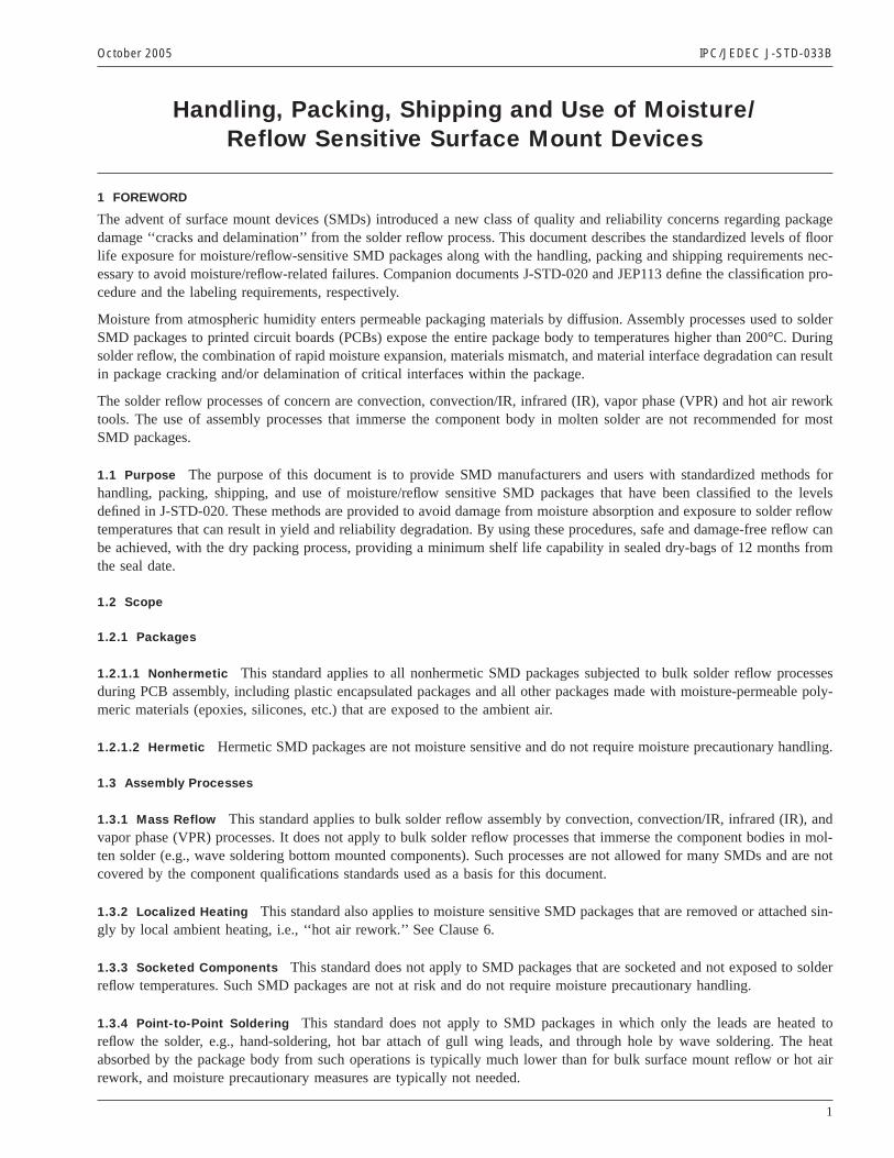
3.3.1 Description Dry pack consists of desiccant material and a Humidity Indicator Card (HIC) sealed with the SMDpackages inside a Moisture Barrier Bag (MBB). A representative dry pack configuration is shown in Figure 3-1.
3.3.2 Materials
3.3.2.1 Moisture Barrier Bag (MBB) The moisture barrier bagshall meet MIL-PRF-81705, TYPE I requirements for flex-ibility, ESD protection, mechanical strength, and puncture resistance. The bagsshall be heat sealable. The Water VaporTransmission Rate (WVTR)shall be≤0.002 gm/100 in2 in 24 hrs at 40°C after flex testing per condition ‘‘E’’ASTM F 392.The WVTR is measured using ASTM F 1249.
3.3.2.2 Desiccant The desiccant materialshall meet MIL-D-3464, TYPE II. Desiccantshall be dustless, noncorrosive,and absorbent to amounts specified in the standard. The desiccantshall be packaged in moisture permeable bags or pouches.The amount of desiccant used, per moisture barrier bag,shall be based on the bag surface area and WVTR in order to limitthe interior relative humidity in the MBB to less than 10% at 25°C.
DesiccantPouches
HumidityIndicator
CardFoamEnd Cap
MoistureBarrier
Bag
IPC-033b-3-1
Figure 3-1 Typical Dry Pack Configuration for Moisture-Sensitive SMD Packages in Shipping Tubes
IPC/JEDEC J-STD-033B October 2005
4
For comparison between various desiccant types, military specifications adopted the ‘‘UNIT’’ as the basic unit of measureof quantity for desiccant material. A UNIT of desiccant is defined as the amount that will absorb a minimum of 2.85 g ofwater vapor at 20% RH and 25°C.
When the desiccant capacity at 10% RH and 25°C is known the following equation should be used.
U = (0.304 * M * WVTR * A)/D
where:U = Amount of desiccant in UNITSM = Shelf life desired in monthsWVTR = Water vapor transmission rate in grams/m2 (grams/100 in2) in 24 hrsA = Total exposed surface area of the MBB in square meters (square inches)D = The amount of water in grams, that a UNIT of desiccant will absorb at 10% RH and 25°C
When the desiccant capacity at 10% RH and 25°C is not known the quantity needed can be estimated using the followingsimplified equation.
U = 5 X 10⁻³ A
where:U = Amount of desiccant in UNITSA = Total exposed surface area of the MBB in square inches
Note: No moisture-absorbing material (e.g., trays, tubes, reels, foam end caps) should be placed in the dry bag without bak-ing. Any such material that is included increases the amount of desiccant needed to meet the calculated shelf life (see 5.3.1)by an amount based on the moisture content of the material. This can be determined by weighing a representative quantityof material known to be at equilibrium with the manufacturing environment, baking to a new constant weight, and subtract-ing the final from the initial weight.
Additional UNIT(s) of desiccant, based on 10% RH @ 25°C, must be added to absorb the amount of water, in grams,egressed from the packing materials (dunnage) after baking.
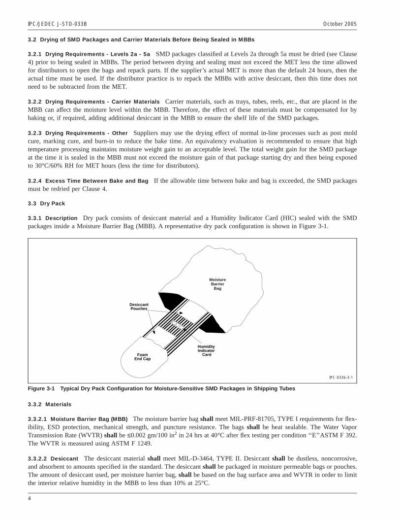
3.3.2.3 Humidity Indicator Card (HIC) At minimum, the HICshall have three (3) color spots with sensitivity values of5%, 10% RH and 60% RH. An example HIC is shown in Figure 3-2. The spotsshall indicate the humidity with a signifi-cant, perceptible change in color (hue) as indicated in Table 3-2, when tested using the test method in Appendix A. The col-ors shall be described in writing on the card.
3.3.2.4 HIC Paper White blotting paper made from fibrous cellulosic material, with a minimum basis weight of, 300 g/m2
(equivalent to a nominal 200 pounds basis weight)shall be used for HICs.
3.3.2.5 Visual Defects HICs shall be free from defects including missing spots, tears, improperly located spots, and indi-cating color overrunning the black circles.
HUMIDITY INDICATORComplies with IPC/JEDEC J-STD-003B
LEVEL2 PARTS
Bake partsif 60% isNOT blue
LEVEL2A-5APARTSBake partsif 10% isNOT blueand 5%is pink
60%
10%
5%
Initial Use: Do not put thiscard into a bag if 60% is pink.
man
ufac
ture
r id
entif
icat
ion
Lot n
umbe
r
IPC-033b-3-2
Figure 3-2 Example Humidity Indicator Card
October 2005 IPC/JEDEC J-STD-033B
5
3.3.2.6 Preservation HICs shall be packaged in a moisture impervious container, typically a metal can containing 125cards. Desiccant conforming to MIL-D-3464shall be included in the container. At a minimum, the 10% spotshall indicatedry when the cards are packaged in the container.
3.3.2.7 Markings The containershall be marked with the part number, description, lot/date number, manufacturer name,quantity of cards, and IPC/JEDEC J-STD-033, including revision level.
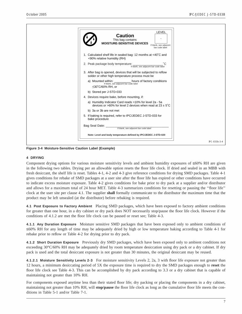
3.3.3 Labels
3.3.3.1 Labels - Moisture Sensitive Identification Labels relevant to the dry pack process are the ‘‘Moisture-SensitiveIdentification’’ (MSID) label and the Caution label as specified in JEDEC JEP113 (see Figures 3-3 and 3-4). The MSID labelshall be affixed to the lowest-level shipping container that contains the MBB. The Caution labelshall be affixed to the out-side surface of the MBB. The Caution label includes fields for the Peak package body temperature allowed during reflowsoldering (the classification temperature per J-STD-020), the floor life, and the bag seal date.
3.3.3.2 Labels - Level 6 Requirements Level 6 parts not shipped in MBBsshall have both an MSID label and the appro-priate Caution label affixed to the lowest level shipping container.
3.3.3.3 Labels - Level 1 Requirements Level 1 parts classified for other than 220°C - 225°C maximum reflow tempera-ture shall have a Caution label with the maximum reflow temperature specified. The Caution labelshall be affixed to theMBB (if used) or to the lowest-level shipping container. The Caution label will not be required if a ‘‘Bar Code’’ labelincludes the Level 1 classification and maximum reflow temperature information in human readable form. Level 1 partsclassified at 220°C - 225°C maximum reflow temperature do not require any moisture related labels.
3.3.4 Moisture Barrier Bag Sealing The bag should be heat sealed so as not to damage or cause delamination of the MBB.Full air evacuation is not needed or recommended; light air evacuation will reduce the packaging bulk and enhance cartonpacking. Excessive evacuation may impede desiccant performance and lead to MBB punctures.
3.3.5 Shelf Life The calculated shelf life for dry packed SMD packagesshall be a minimum of 12 months from the bagseal date, when stored in a noncondensing atmospheric environment of <40°C/90% RH.
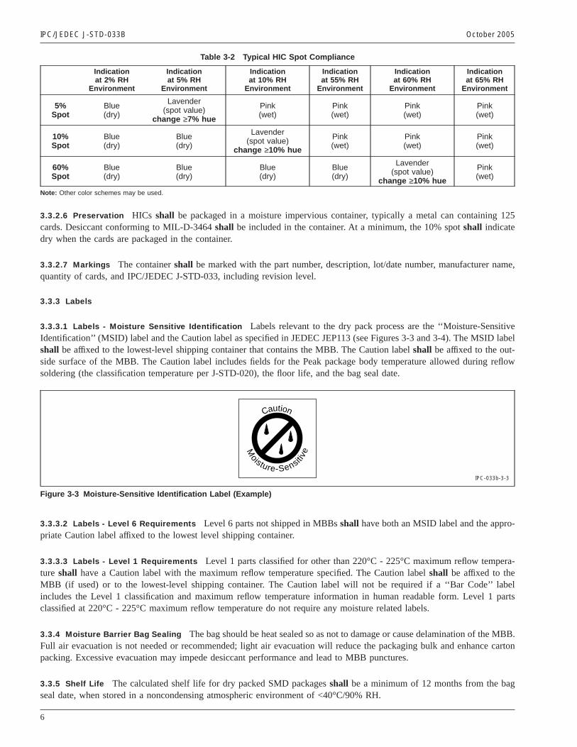
Table 3-2 Typical HIC Spot Compliance
Indicationat 2% RH
Environment
Indicationat 5% RH
Environment
Indicationat 10% RH
Environment
Indicationat 55% RH
Environment
Indicationat 60% RH
Environment
Indicationat 65% RH
Environment
5%Spot
Blue(dry)
Lavender(spot value)
change ≥7% hue
Pink(wet)
Pink(wet)
Pink(wet)
Pink(wet)
10%Spot
Blue(dry)
Blue(dry)
Lavender(spot value)
change ≥10% hue
Pink(wet)
Pink(wet)
Pink(wet)
60%Spot
Blue(dry)
Blue(dry)
Blue(dry)
Blue(dry)
Lavender(spot value)
change ≥10% hue
Pink(wet)
Note: Other color schemes may be used.
Moisture-Sensiti
ve
Caution
IPC-033b-3-3
Figure 3-3 Moisture-Sensitive Identification Label (Example)
IPC/JEDEC J-STD-033B October 2005
6
4 DRYING
Component drying options for various moisture sensitivity levels and ambient humidity exposures of≤60% RH are givenin the following two tables. Drying per an allowable option resets the floor life clock. If dried and sealed in an MBB withfresh desiccant, the shelf life is reset. Tables 4-1, 4-2 and 4-3 give reference conditions for drying SMD packages. Table 4-1gives conditions for rebake of SMD packages at a user site after the floor life has expired or other conditions have occurredto indicate excess moisture exposure. Table 4-2 gives conditions for bake prior to dry pack at a supplier and/or distributorand allows for a maximum total of 24 hour MET. Table 4-3 summarizes conditions for resetting or pausing the ‘‘floor life’’clock at the user site per clause 4.1. The suppliershall formally communicate to the distributor the maximum time that theproduct may be left unsealed (at the distributor) before rebaking is required.
4.1 Post Exposure to Factory Ambient Placing SMD packages, which have been exposed to factory ambient conditionsfor greater than one hour, in a dry cabinet or dry pack does NOT necessarily stop/pause the floor life clock. However if theconditions of 4.1.2 are met the floor life clock can be paused or reset see; Table 4-3.
4.1.1 Any Duration Exposure Moisture sensitive SMD packages that have been exposed only to ambient conditions of≤60% RH for any length of time may be adequately dried by high or low temperature baking according to Table 4-1 forrebake prior to reflow or Table 4-2 for drying prior to dry pack.
4.1.2 Short Duration Exposure Previously dry SMD packages, which have been exposed only to ambient conditions notexceeding 30°C/60% RH may be adequately dried by room temperature desiccation using dry pack or a dry cabinet. If drypack is used and the total desiccant exposure is not greater than 30 minutes, the original desiccant may be reused.
4.1.2.1 Moisture Sensitivity Levels 2-3 For moisture sensitivity Levels 2, 2a, 3 with floor life exposure not greater than12 hours, a minimum desiccating period of 5X the exposure time is required to dry the SMD packages enough toreset thefloor life clock see Table 4-3. This can be accomplished by dry pack according to 3.3 or a dry cabinet that is capable ofmaintaining not greater than 10% RH.
For components exposed anytime less than their stated floor life; dry packing or placing the components in a dry cabinet,maintaining not greater than 10% RH, willstop/pausethe floor life clock as long as the cumulative floor life meets the con-ditions in Table 5-1 and/or Table 7-1.
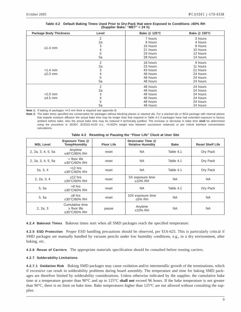
Caution
1. Calculated shelf life in sealed bag: 12 months at <40˚C and<90% relative humidity (RH)
2. Peak package body temperature: __________________˚CIf blank, see adjacent bar code label
3. After bag is opened, devices that will be subjected to reflowsolder or other high temperature process must be
a) Mounted within: __________ hours of factory conditionsIf blank, see adjacent bar code label
<30˚C/60% RH, or
b) Stored per J-STD-033
4. Devices require bake, before mounting, if:
a) Humidity Indicator Card reads >10% for level 2a - 5adevices or >60% for level 2 devices when read at 23 ± 5˚C
b) 3a or 3b are not met
5. If baking is required, refer to IPC/JEDEC J-STD-033 forbake procedure
Bag Seal Date: ____________________________________If blank, see adjacent bar code label
Note: Level and body temperature defined by IPC/JEDEC J-STD-020
This bag containsMOISTURE-SENSITIVE DEVICES
LEVEL
If blank, see adjacentbar code label
_
IPC-033b-3-4
Figure 3-4 Moisture-Sensitive Caution Label (Example)
October 2005 IPC/JEDEC J-STD-033B
7

4.1.2.2 Moisture Sensitivity Levels 4, 5, 5a For moisture sensitivity Levels 4, 5, 5a with floor life exposure not greaterthan eight hours, a minimum desiccating period of 10X the exposure time is required to dry the SMD packages enough toreset the floor life clock see Table 4-3. This can be accomplished by dry pack according to 3.3 or a dry cabinet that is capableof maintaining not greater than 5% RH.
Once the floor life clock has been reset, refer to 5.3 for safe storage conditions.
4.2 General Considerations for Baking The oven used for bakingshall be vented and capable of maintaining the requiredtemperatures at less than 5% RH.
4.2.1 High Temperature Carriers Unless otherwise indicated by the manufacturer, SMD packages shipped in high tem-perature carriers can be baked in the carriers at 125°C.
4.2.2 Low Temperature Carriers SMD packages shipped in low temperature carriers may not be baked in the carriers atany temperature higher than 40°C. If a higher bake temperature is required, SMD packages must be removed from the lowtemperature carriers to thermally safe carriers, baked, and returned to the low temperature carriers.
Note 1.Manual handling may increase the risk of mechanical and/or ESD damage.
Note 2. If SMD packages are placed in dry bags with unbaked carriers, refer to 3.3.2.2.
4.2.3 Paper and Plastic Container Items Paper and plastic container items such as cardboard boxes, bubble pack, plas-tic wrap, etc.,shall be removed from around the carriers prior to baking. Rubber bands around tubes and plastic tray tiesmust also be removed prior to high temperature (125°C) bake.
Table 4-1 Reference Conditions for Drying Mounted or Unmounted SMD Packages(User Bake: Floor life begins counting at tim e = 0 after bake)
Package Body Level
Bake @ 125°CBake @ 90°C
≤5% RHBake @ 40°C
≤5% RH
ExceedingFloor Lifeby >72 h
ExceedingFloor Lifeby ≤72 h
ExceedingFloor Lifeby >72 h
ExceedingFloor Lifeby ≤72 h
ExceedingFloor Lifeby >72 h
ExceedingFloor Lifeby ≤72 h
Thickness≤1.4 mm
2 5 hours 3 hours 17 hours 11 hours 8 days 5 days
2a 7 hours 5 hours 23 hours 13 hours 9 days 7 days
3 9 hours 7 hours 33 hours 23 hours 13 days 9 days
4 11 hours 7 hours 37 hours 23 hours 15 days 9 days
5 12 hours 7 hours 41 hours 24 hours 17 days 10 days
5a 16 hours 10 hours 54 hours 24 hours 22 days 10 days
Thickness>1.4 mm≤2.0 mm
2 18 hours 15 hours 63 hours 2 days 25days 20 days
2a 21 hours 16 hours 3 days 2 days 29 days 22 days
3 27 hours 17 hours 4 days 2 days 37 days 23 days
4 34 hours 20 hours 5 days 3 days 47 days 28 days
5 40 hours 25 hours 6 days 4 days 57 days 35 days
5a 48 hours 40 hours 8 days 6 days 79 days 56 days
Thickness>2.0 mm≤4.5 mm
2 48 hours 48 hours 10 days 7 days 79 days 67 days
2a 48 hours 48 hours 10 days 7 days 79 days 67 days
3 48 hours 48 hours 10 days 8 days 79 days 67 days
4 48 hours 48 hours 10 days 10 days 79 days 67 days
5 48 hours 48 hours 10 days 10 days 79 days 67 days
5a 48 hours 48 hours 10 days 10 days 79 days 67 days
BGA package>17 mm x 17 mm
or any stackeddie package(See Note 2)
2-6 96 hours As aboveper package
thickness andmoisture level
Not applicable As aboveper package
thickness andmoisture level
Not applicable As aboveper package
thickness andmoisture level
Note 1: Table 4-1 is based on worst-case molded lead frame SMD packages. Users may reduce the actual bake time if technically justified (e.g., absorption/desorption data, etc.). In most cases it is applicable to other nonhermetic surface mount SMD packages.
Note 2: For BGA packages >17 mm x 17 mm, that do not have internal planes that block the moisture diffusion path in the substrate, may use bake timesbased on the thickness/moisture level portion of the table.
Note 3: If baking of packages >4.5 mm thick is required see appendix B.
IPC/JEDEC J-STD-033B October 2005
8
4.2.4 Bakeout Times Bakeout times start when all SMD packages reach the specified temperature.
4.2.5 ESD Protection Proper ESD handling precautions should be observed, per EIA-625. This is particularly critical ifSMD packages are manually handled by vacuum pencils under low humidity conditions, e.g., in a dry environment, afterbaking, etc.
4.2.6 Reuse of Carriers The appropriate materials specification should be consulted before reusing carriers.
4.2.7 Solderability Limitations
4.2.7.1 Oxidation Risk Baking SMD packages may cause oxidation and/or intermetallic growth of the terminations, whichif excessive can result in solderability problems during board assembly. The temperature and time for baking SMD pack-ages are therefore limited by solderability considerations. Unless otherwise indicated by the supplier, the cumulative baketime at a temperature greater than 90°C and up to 125°Cshall not exceed 96 hours. If the bake temperature is not greaterthan 90°C, there is no limit on bake time. Bake temperatures higher than 125°C are not allowed without consulting the sup-plier.
Table 4-2 Default Baking Times Used Prior to Dry-Pack that were Exposed to Conditions ≥60% RH(Supplier Bake: ‘‘MET’’ = 24 h)
Package Body Thickness Level Bake @ 125°C Bake @ 150°C
≤1.4 mm
22a3455a
7 hours8 hours
16 hours21 hours24 hours28 hours
3 hours4 hours8 hours
10 hours12 hours14 hours
>1.4 mm≤2.0 mm
22a3455a
18 hours23 hours43 hours48 hours48 hours48 hours
9 hours11 hours21 hours24 hours24 hours24 hours
>2.0 mm≤4.5 mm
22a3455a
48 hours48 hours48 hours48 hours48 hours48 hours
24 hours24 hours24 hours24 hours24 hours24 hours
Note 1: If baking of packages >4.5 mm thick is required see appendix B.Note 2: The bake times specified are conservative for packages without blocking planes or stacked die. For a stacked die or BGA package with internal planes
that impede moisture diffusion the actual bake time may be longer than that required in Table 4-2 if packages have had extended exposure to factoryambient before bake. Also the actual bake time may be reduced if technically justified. The increase or decrease in bake time shall be determinedusing the procedure in JEDEC JESD22-A120 (i.e., <0.002% weight loss between successive readouts) or per critical interface concentrationcalculations.
Table 4-3 Resetting or Pausing the ‘‘Floor Life’’ Clock at User Site
MSL LevelExposure Time @
Temp/Humidity Floor LifeDesiccator Time @Relative Humidity Bake Reset Shelf Life
2, 2a, 3, 4, 5, 5a Anytime≤40°C/85% RH reset NA Table 4.1 Dry Pack
2, 2a, 3, 4, 5, 5a > floor life≤30°C/60% RH reset NA Table 4.1 Dry Pack
2a, 3, 4 >12 hrs≤30°C/60% RH reset NA Table 4.1 Dry Pack
2, 2a, 3, 4 ≤12 hrs≤30°C/60% RH reset 5X exposure time
≤10% RH NA NA
5, 5a >8 hrs≤30°C/60% RH reset NA Table 4.1 Dry Pack
5, 5a ≥8 hrs≤30°C/60% RH reset 10X exposure time
≤5% RH NA NA
2, 2a, 3Cumulative time
≥ floor life≤30°C/60% RH
pause Anytime≤10% RH NA NA
October 2005 IPC/JEDEC J-STD-033B
9
4.2.7.2 Carrier Out-gassing Risk Care should be taken to ensure that out-gassing of materials from the component carri-ers does not occur to any significant extent, such that solderability might be affected.
5 USE
Upon opening the MBB, the floor life clock starts. If an MBB is opened and the SMD packages will not be used within thespecified floor life, the procedures in Clause 7 should be followed.
5.1 Incoming Bag Inspection
5.1.1 Upon Receipt Dry packed SMD packages should be inspected for a bag seal date located on the caution or bar codelabel to determine remaining shelf life. The bags should be inspected to verify there are no holes, gouges, tears, puncturesor openings of any kind that would expose either the contents or an inner layer of a multilayer bag. If openings are found,and the humidity indicator card (HIC) indicates maximum humidity has been exceeded, then the parts should be baked for48 hours at 125°C or using the saturated bake times of Table 4-1.
5.1.2 Component Inspection Intact bags may be opened for component inspection by cutting at the top of the bag nearthe seal. If the bags are opened under factory ambient conditions, (see 4.1.2).
5.2 Floor Life The floor life of SMDs per Table 5-1 will be modified by environmental conditions other than 30°C/60%RH. Refer to Clause 7 to determine maximum allowable time before rebake would be necessary. If partial lots are used, theremaining SMD packages must be resealed or placed in safe storage within one hour of bag opening (see 5.3). If one hourexposure is exceeded, refer to 4.1.
5.3 Safe Storage ‘Safe storage’ means dry SMD packages held in a controlled humidity condition such that the floor lifeclock remains at zero. Acceptable safe storage conditions for SMD packages classified as Level 2 through 5a are listedbelow.
5.3.1 Dry Pack Dry packed SMD packages in intact MBBs, stored per 3.3,shall have a calculated shelf life of at least 12months from the bag seal date shown on the caution or bar code label.
5.3.2 Shelf Life The minimum calculated shelf life is 12 months from bag seal date. If the actual shelf life has exceeded12 months and the humidity indicator card (HIC) (see 5.5.1) indicates that baking is not required, then it is safe to reflowthe components per the original MSL rating. Although unanticipated, factors other than moisture sensitivity could affect thetotal shelf life of components.
Note: An HIC that has been continuously sealed in the MBB is typically accurate up to five years.
5.3.3 Dry Atmosphere Cabinet Storage cabinets which maintain low humidity by purging with dry air or nitrogen at 25± 5°C. The cabinets must be capable of recovering to their stated humidity rating within one hour from routine excursionssuch as door opening/closing.
5.3.3.1 Dry Cabinet at 10% RH SMD packages not sealed in a MBB may be placed in a dry atmosphere cabinet, main-tained at not greater than 10% RH. These dry cabinets should not be considered a MBB. Storage of SMD packages in thesedry cabinets should be limited to a maximum time per Table 7-1. If the time limit is exceeded they should be baked accord-ing to Table 4-2 to restore the floor life.
Table 5-1 Moisture Classification Level and Floor Life
LevelFloor Life (out of bag) at factory
ambient ≤30°C/60% RH or as stated
1 Unlimited at ≤30°C/85% RH
2 1 year
2a 4 weeks
3 168 hours
4 72 hours
5 48 hours
5a 24 hours
6 Mandatory bake before use. After bake, must be reflowed within the time limit specified on the label.
IPC/JEDEC J-STD-033B October 2005
10
5.3.3.2 Dry Cabinet at 5% RH SMD packages not sealed in a MBB may be placed in a dry atmosphere cabinet, main-tained at not greater than 5% RH. Storage in these dry cabinets may be considered equivalent to storage in a MBB withunlimited shelf life.
5.4 Reflow Reflow includes single and multi-pass assembly reflow and single component attach/removal for rework.
5.4.1 Opened MBB After a dry pack (MBB) has been opened, all SMD packages within that bag must complete all sol-der reflow processing, including rework, prior to the stated floor life, resealed in the MBB, or stored in a dry atmospherecabinet per 4.1. If the floor life or factory ambient conditions are exceeded, refer to 5.5.2.
5.4.2 Reflow Temperature Extremes During reflow the component body temperature must not exceed the rated value,stated on the Caution label. The body temperature during reflow directly influences component reliability.
Note 1.The component body temperature may be very different from the lead or solder ball temperature, particularly in IRand IR/convection processes, and should be checked separately.
Note 2. Some hot air attach processes may require heating the component body to temperatures hotter than 225°C. If thattemperature exceeds the classification temperature, moisture precautions and/or time-temperature limitations beyond thescope of this specification may be required. The supplier should be consulted.
5.4.3 Additional Thermal Profile Parameters During reflow, the additional thermal profile parameters stated in JESD22-A113 should not be exceeded. Although the body temperature during reflow is the most critical parameter, other profileparameters such as the total exposure time to hot temperatures, and the heating rates, may also influence component reli-ability.
5.4.4 Multiple Reflow Passes If more than one reflow pass is used, care must be taken to ensure that no moisture sensi-tive SMD packages, mounted or unmounted, have exceeded their floor life prior to the final pass. If any component on theboard has exceeded its floor life the board needs to be baked prior to the next reflow. Clause 6 should be referenced for thebaking of populated boards.
Note: The floor life clock is NOT reset by any reflow or rework process.
For cavity packages in which water may be entrapped, water clean processes after the first reflow can be an additional sourceof moisture. This may present an additional risk, which should be evaluated.
5.4.5 Maximum Reflow Passes A maximum of three reflow passes is allowed per component. If more than three arerequired for any reason, the supplier must be consulted (reference J-STD-020).
5.5 Drying Indicators Events and conditions, that require component drying prior to reflow or continued safe storage.
5.5.1 Excess Humidity in the Dry Pack Excess humidity in the dry pack is noted by the humidity indicator card (HIC).It can occur due to misprocessing (e.g., missing or inadequate desiccant), mishandling (e.g., tears or rips in the MBB), orimproper storage.
The HIC should be read immediately upon removal from the MBB. For best accuracy, the HIC should be read at 23 ± 5°C.The following conditions apply regardless of the storage time, i.e., whether or not the shelf life has been exceeded.
Note: ‘‘Witness’’ cards may be available from the HIC manufacturer if needed to confirm the wet/dry colors.
5.5.1.1 HIC Indication 1 If the 5%, 10% and 60% RH spots indicate dry, then Levels 2, 2a 3, 4, 5, and 5a parts are stilladequately dry. If the bag is to be resealed refer to 4.1.
5.5.1.2 HIC Indication 2 If the 5% RH spot indicates wet and the 10% RH spot does not indicate dry, and the 60% spotindicates dry, the Levels 2a, 3, 4, 5, and 5a have been exposed to an excessive level of moisture, and dryingshall be doneper Clause 4. Level 2 parts are still adequately dry
5.5.1.3 HIC Indication 3 If the 5%, 10%, and 60% RH spots indicate wet, Level 2 parts have been exposed to an exces-sive level of moisture, and dryingshall be done per Clause 4.
Note: Discard HICs where the 60% spot indicates wet.
October 2005 IPC/JEDEC J-STD-033B
11
5.5.2 Floor Life or Ambient Temperature/Humidity Exceeded If the floor life or ambient temperature/humidity condi-tions per Table 5-1 have been exceeded, SMD packages must be dried per Clause 4 prior to reflow or safe storage.
If the factory ambient temperature and/or humidity conditions per Table 5-1 cannot be met, the component floor life mustbe derated to compensate. Floor life derating is discussed in Clause 7.
5.5.3 Level 6 SMD Packages SMD packages classified as Level 6 must be dried by baking, then reflowed within the timelimit specified on the label.
6 BOARD REWORK
6.1 Component Removal, Rework and Remount If a component is to be removed from the board, it is recommended thatlocalized heating be used and the maximum body temperatures of any surface mount component on the board not exceed200°C. This method will minimize moisture related component damage. If any component temperature exceeds 200°C, theboard must be baked dry per 6.2 prior to rework and/or component removal. Component temperaturesshall be measured atthe top center of the package body. Any SMD package that has not exceeded its floor life can be exposed to a maximumbody temperature as high as its maximum reflow temperature as defined by J-STD-020.
6.1.1 Removal for Failure Analysis Not following the requirements of 6.1 may cause moisture/reflow damage that couldhinder or completely prevent the determination of the original failure mechanism.
6.1.2 Removal and Remount Removal and reinstallation or replacement of a component should be conducted followingIPC-7711 or IPC-7721. If a component is to be removed and reinstalled it may be necessary to first bake the printed wir-ing assembly to eliminate moisture from the component. Table 4-1 may be used as a guide in identifying an appropriatebake cycle. When identifying a bake cycle the maximum exposure temperature and maximum rate of temperature changeof components and materials on the subject printed wiring assembly must be considered and an appropriate time tempera-ture profile (see IPC-7711) used. An SMD packageshall not exceed its MSL ratings per J-STD-020 at any time duringreplacement. Localized replacement reflow heating is recommended, so that the entire board is not re-subjected to reflowtemperature profiles.
Note: Temperatures on neighboring SMD packages above the melting point of the solder being used may cause some sol-der joints to partially reflow, which may result in a potential solder joint reliability concern.
6.2 Baking of Populated Boards A default board assembly bake-out temperature of 125°Cshall be used, except in caseswhere components and/or board materials cannot withstand this condition. Examples of temperature sensitive componentsinclude organic LEDs, batteries and electrolytic capacitors. With component and board temperature restrictions in mind,choose a bake temperature from Table 4-1; then determine the appropriate bake duration based on the component to beremoved. For additional considerations see IPC-7711 and IPC-7721.
7 DERATING DUE TO FACTORY ENVIRONMENTAL CONDITIONS
Factory floor life exposures for SMD packages removed from the dry bags will be a function of the ambient environmentalconditions. A safe, yet conservative, handling approach is to expose the SMD packages only up to the maximum time lim-its for each moisture sensitivity level as shown in Table 5-1. This approach, however, does not work if the factory humidityor temperature is greater than the testing conditions of 30°C/60% RH. A solution for addressing this problem is to derate theexposure times based on the knowledge of moisture diffusion in the component packaging materials (ref. JESD22- A120).Recommended equivalent total floor life exposures can be estimated for a range of humidities and temperatures based onthe worst case exposure conditions and the nominal plastic thickness for each device. Table 7-1 lists equivalent derated floorlives for humidities ranging from 5-90% RH for temperatures of 20°C, 25°C, 30°C and 35°C. This table is applicable toSMDs molded with novolac, biphenyl or multifunctional epoxy mold compounds. The following assumptions were used incalculating Table 7-1:
1. Activation Energy for diffusion = 0.35eV (smallest known value).
2. For ≤60% RH, use Diffusivity = 0.121exp (- 0.35eV/kT) mm2/s (this uses smallest known Diffusivity @ 30°C).
3. For >60% RH, use Diffusivity = 1.320exp (- 0.35eV/kT) mm2/s (this uses largest known Diffusivity @ 30°C).
IPC/JEDEC J-STD-033B October 2005
12
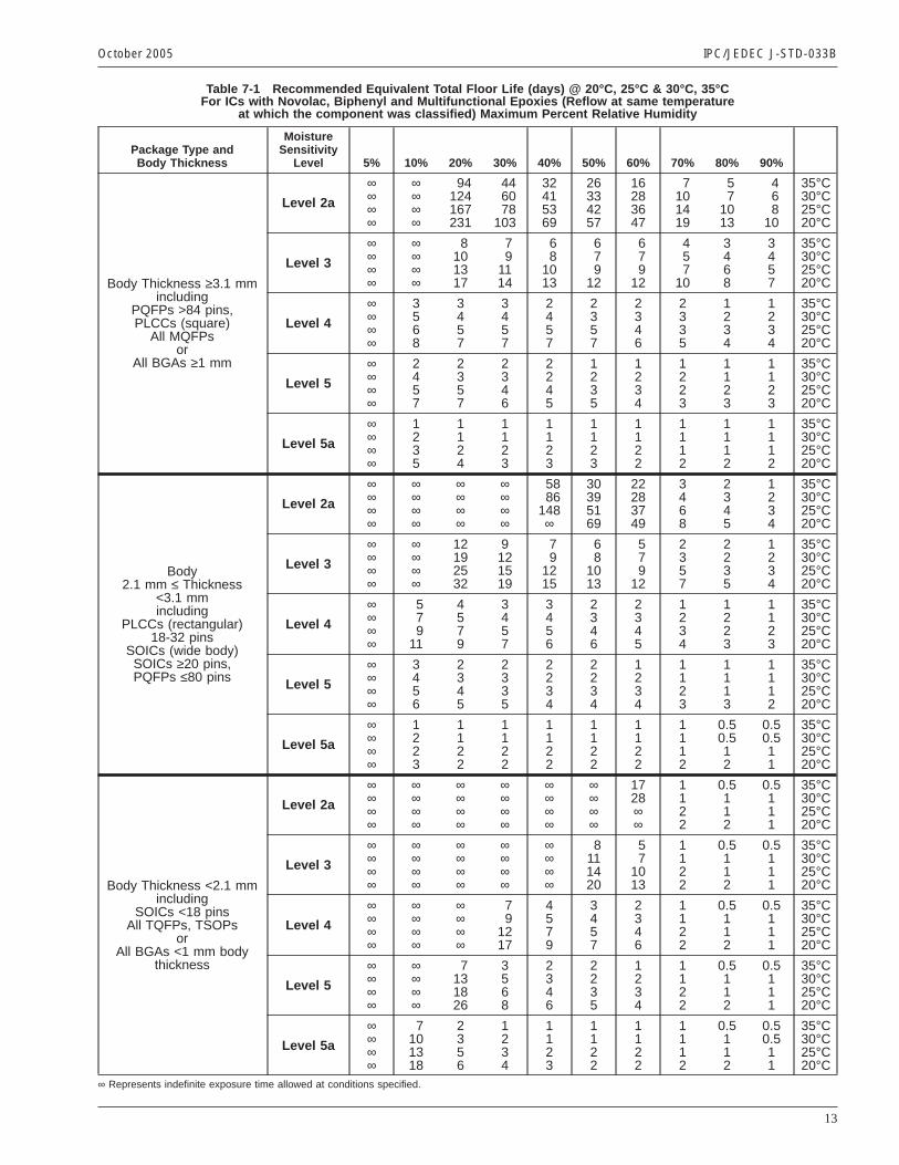
Table 7-1 Recommended Equivalent Total Floor Life (days) @ 20°C, 25°C & 30°C, 35°CFor ICs with Novolac, Biphenyl and Multifunctional Epoxies (Reflow at same temperature
at which the component was classified) Maximum Percent Relative Humidity
Package Type andBody Thickness
MoistureSensitivity
Level 5% 10% 20% 30% 40% 50% 60% 70% 80% 90%
Body Thickness ≥3.1 mmincluding
PQFPs >84 pins,PLCCs (square)
All MQFPsor
All BGAs ≥1 mm
Level 2a
∞∞∞∞
∞∞∞∞
94124167231
446078
103
32415369
26334257
16283647
7101419
57
1013
468
10
35°C30°C25°C20°C
Level 3
∞∞∞∞
∞∞∞∞
8101317
79
1114
68
1013
679
12
679
12
457
10
3468
3457
35°C30°C25°C20°C
Level 4
∞∞∞∞
3568
3457
3457
2457
2357
2346
2335
1234
1234
35°C30°C25°C20°C
Level 5
∞∞∞∞
2457
2357
2346
2245
1235
1234
1223
1123
1123
35°C30°C25°C20°C
Level 5a
∞∞∞∞
1235
1124
1123
1123
1123
1122
1112
1112
1112
35°C30°C25°C20°C
Body2.1 mm ≤ Thickness
<3.1 mmincluding
PLCCs (rectangular)18-32 pins
SOICs (wide body)SOICs ≥20 pins,PQFPs ≤80 pins
Level 2a
∞∞∞∞
∞∞∞∞
∞∞∞∞
∞∞∞∞
5886
148∞
30395169
22283749
3468
2345
1234
35°C30°C25°C20°C
Level 3
∞∞∞∞
∞∞∞∞
12192532
9121519
79
1215
68
1013
579
12
2357
2235
1234
35°C30°C25°C20°C
Level 4
∞∞∞∞
579
11
4579
3457
3456
2346
2345
1234
1223
1123
35°C30°C25°C20°C
Level 5
∞∞∞∞
3456
2345
2335
2234
2234
1234
1123
1113
1112
35°C30°C25°C20°C
Level 5a
∞∞∞∞
1223
1122
1122
1122
1122
1122
1112
0.50.512
0.50.511
35°C30°C25°C20°C
Body Thickness <2.1 mmincluding
SOICs <18 pinsAll TQFPs, TSOPs
orAll BGAs <1 mm body
thickness
Level 2a
∞∞∞∞
∞∞∞∞
∞∞∞∞
∞∞∞∞
∞∞∞∞
∞∞∞∞
1728∞∞
1122
0.5112
0.5111
35°C30°C25°C20°C
Level 3
∞∞∞∞
∞∞∞∞
∞∞∞∞
∞∞∞∞
∞∞∞∞
8111420
57
1013
1122
0.5112
0.5111
35°C30°C25°C20°C
Level 4
∞∞∞∞
∞∞∞∞
∞∞∞∞
79
1217
4579
3457
2346
1122
0.5112
0.5111
35°C30°C25°C20°C
Level 5
∞∞∞∞
∞∞∞∞
7131826
3568
2346
2235
1234
1122
0.5112
0.5111
35°C30°C25°C20°C
Level 5a
∞∞∞∞
7101318
2356
1234
1123
1122
1122
1112
0.5112
0.50.511
35°C30°C25°C20°C
∞ Represents indefinite exposure time allowed at conditions specified.
October 2005 IPC/JEDEC J-STD-033B
13
Appendix ATest Method for Humidity Indicator Card
used with Electronic Component Packaging
Note: It is intended to make the HIC test method and criteria a separate standard in the future.
HIC Testing Method To function properly, the spots must show a visually perceptible color change to indicate a change inthe amount of humidity. This testing method uses a colorimeter to measure the color (hue) of humidity indicating spots. Thepercentage of change in hue from one humidity value to another is then calculated.
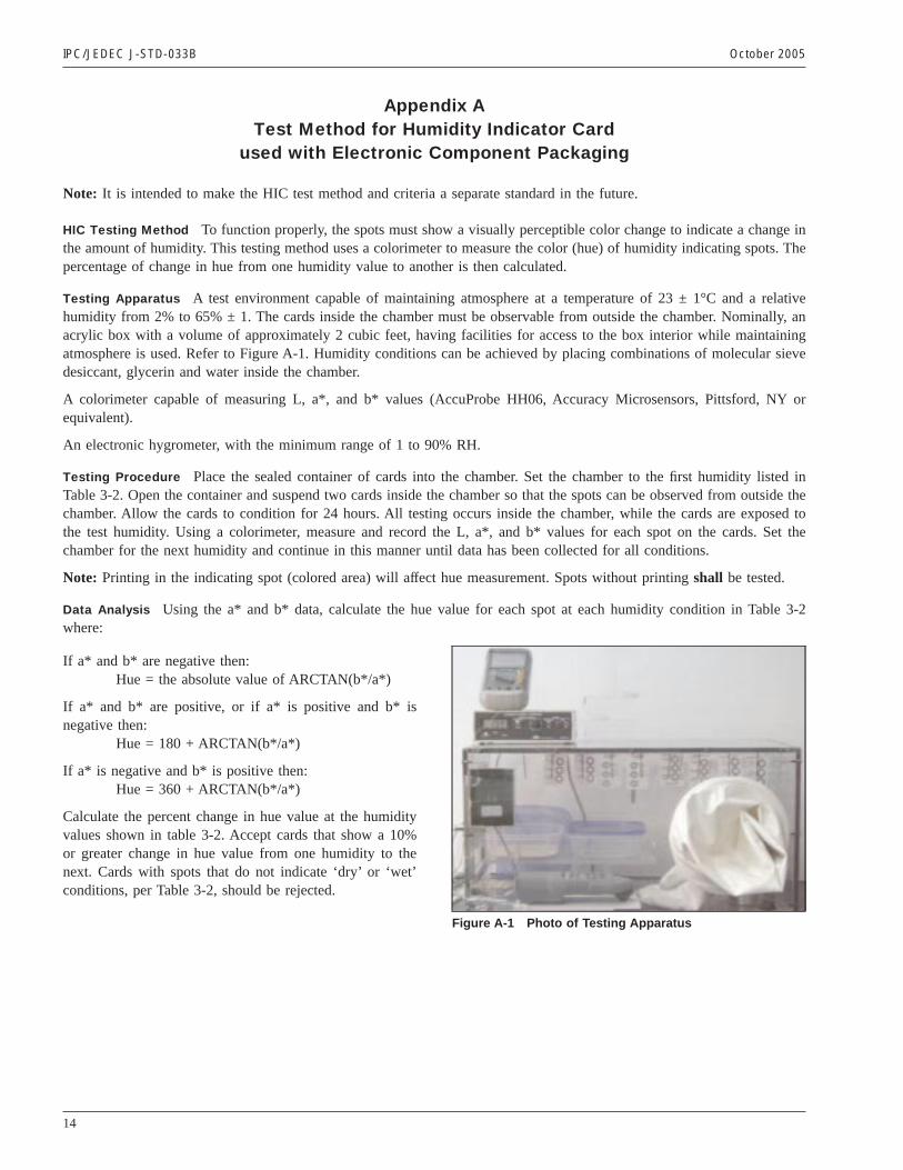
Testing Apparatus A test environment capable of maintaining atmosphere at a temperature of 23 ± 1°C and a relativehumidity from 2% to 65% ± 1. The cards inside the chamber must be observable from outside the chamber. Nominally, anacrylic box with a volume of approximately 2 cubic feet, having facilities for access to the box interior while maintainingatmosphere is used. Refer to Figure A-1. Humidity conditions can be achieved by placing combinations of molecular sievedesiccant, glycerin and water inside the chamber.
A colorimeter capable of measuring L, a*, and b* values (AccuProbe HH06, Accuracy Microsensors, Pittsford, NY orequivalent).
An electronic hygrometer, with the minimum range of 1 to 90% RH.
Testing Procedure Place the sealed container of cards into the chamber. Set the chamber to the first humidity listed inTable 3-2. Open the container and suspend two cards inside the chamber so that the spots can be observed from outside thechamber. Allow the cards to condition for 24 hours. All testing occurs inside the chamber, while the cards are exposed tothe test humidity. Using a colorimeter, measure and record the L, a*, and b* values for each spot on the cards. Set thechamber for the next humidity and continue in this manner until data has been collected for all conditions.
Note: Printing in the indicating spot (colored area) will affect hue measurement. Spots without printingshall be tested.
Data Analysis Using the a* and b* data, calculate the hue value for each spot at each humidity condition in Table 3-2where:
If a* and b* are negative then:Hue = the absolute value of ARCTAN(b*/a*)
If a* and b* are positive, or if a* is positive and b* isnegative then:
Hue = 180 + ARCTAN(b*/a*)
If a* is negative and b* is positive then:Hue = 360 + ARCTAN(b*/a*)
Calculate the percent change in hue value at the humidityvalues shown in table 3-2. Accept cards that show a 10%or greater change in hue value from one humidity to thenext. Cards with spots that do not indicate ‘dry’ or ‘wet’conditions, per Table 3-2, should be rejected.
Figure A-1 Photo of Testing Apparatus
IPC/JEDEC J-STD-033B October 2005
14

Appendix BDerivation of Bake Tables
Bake Tables 4.1 and 4.2 were calculated using the following assumptions/approach:1. Assume Fickian 1-D diffusion and Henry’s Law apply:
∂C∂t
= D∂2C
∂x2(Fick’s Law)
CSat (@ surface)∝ % RH in ambient atmosphere (Henry’s Law)
Where C as a function of time (t) is:
C(t) = CSat(1 − 4π Σ
n=0
∞ { (−1)n
(2n + 1) e −D (2n+1)2 π2t / 4L2} )2. Diffusivity = 6.2 exp(-0.445eV/kT) mm2/s, (assumes slow diffusing mold compound)
a. D30C = 2.48x10⁻⁷ mm2/sb. D40C = 4.27x10⁻⁷ mm2/sc. D90C = 4.13x10⁻⁶ mm2/sd. D125C = 1.44x10⁻⁵ mm2/s
3. Define:a. Lcenterline= critical thickness, e.g., thickness of package / 2b. CCritical = concentration atLcenterlinefor given MSL (based on 30°C/60% RH exposure + 24 hr MET preconditioning)c. CCenterline= concentration atLcenterlinefor any exposure condition
4. Impose following two exposure conditions:a. MSL + >72 hr exposure (assume saturated at 30°C/85% RH where CSat = 7.8 mg/cm3)b. MSL + ≤72 hr exposure (assume ambient at 30°C/60% RH where CSat = 5.3 mg/cm3
5. Calculate minimum time @ Bake temperature for cases 4a and 4b where an additional MSL exposure will keep CCenterline
< CCritical.
Ref: R. L. Shook and J. P. Goodelle, ‘‘Handling of Highly-Moisture Sensitive Components - An Analysis of Low-HumidityContainment and Baking Schedules,’’ ECTC, 1999, pp. 809-15.
MSL + MET
Bake{MSL0hr
Time (hours)
CCriticalM
oist
ure
Con
cent
ratio
n @
Cen
terli
ne
October 2005 IPC/JEDEC J-STD-033B
15

This Page Intentionally Left Blank
IPC/JEDEC J-STD-033B October 2005
16
Standard Improvement Form IPC/JEDEC J-STD-033BThe purpose of this form is to provide theTechnical Committee of IPC with inputfrom the industry regarding usage ofthe subject standard.
Individuals or companies are invited tosubmit comments to IPC. All commentswill be collected and dispersed to theappropriate committee(s).
If you can provide input, please completethis form and return to:
IPC3000 Lakeside Drive, Suite 309SBannockburn, IL 60015-1219Fax 847 615.7105E-mail: [email protected]
1. I recommend changes to the following:
Requirement, paragraph number
Test Method number , paragraph number
The referenced paragraph number has proven to be:
Unclear Too Rigid In Error
Other
2. Recommendations for correction:
3. Other suggestions for document improvement:
Submitted by:
Name Telephone
Company E-mail
Address
City/State/Zip Date

This Page Intentionally Left Blank


ASSOCIATION CONNECTINGELECTRONICS INDUSTRIES
3000 Lakeside Drive, Suite 309S, Bannockburn, IL 60015-1219Tel. 847.615.7100 Fax 847.615.7105
www.ipc.org
®
ISBN #1-580987-67-2


![4. 5. 6. JOINT] JOINT T P JOINT T P JOINT C 18 H JOINT C T ... ken-syoumei.pdf4. 5. 6. JOINT] JOINT T P JOINT T P JOINT C 18 H JOINT C T. P JOINT JOINT a C (2) JOINT x (3) JOINT x](https://img.pdfslide.us/doc/110x75/611edb438155026709151f58/4-5-6-joint-joint-t-p-joint-t-p-joint-c-18-h-joint-c-t-ken-4-5-6-joint.jpg)