Embed Size (px)
Citation preview
13th International LS-DYNA Users Conference Session: Simulation
1-1
Numerical Investigation of Landslide Mobility and Debris-Resistant Flexible Barrier with LS-DYNA®
Yuli Huang, Jack Yiu, Jack Pappin, and Richard Sturt
Arup
Julian S. H. Kwan and Ken K. S. Ho Geotechnical Engineering Office, Civil Engineering & Development Department,
Hong Kong SAR Government
Abstract Driven by the initiative of the Geotechnical Engineering Office, Civil Engineering and Development Department of Hong Kong, Arup is undertaking a pilot numerical investigation of the landslide dynamics and the interaction of landslide debris flow and flexible barriers. Such modeling work is technically challenging as it calls for both sophisticated debris mobility analysis and structural assessment of flexible barriers. The multi-purpose finite element program, LS-DYNA, has therefore been used to carry out the numerical analysis. This paper presents the modeling methodology for landslide mobility and flexible barriers, and assessments with the USGS laboratory flume tests, the full-scale rockfall tests, the 2008 Yu Tung Road debris flow event in Hong Kong, and Illgraben flexible barrier field test in Switzerland. The excellent correlation suggests that the proposed methodology is promising for numerical investigation on landslide mobility and its interaction with flexible barriers.
Introduction
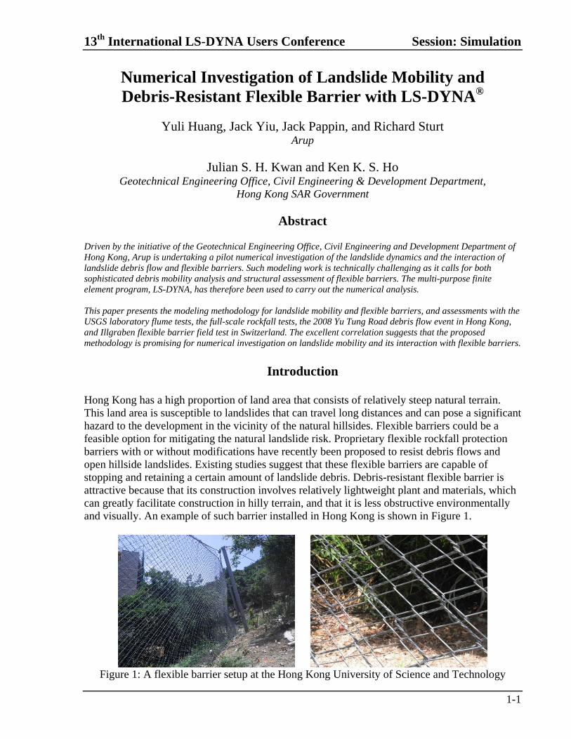
Hong Kong has a high proportion of land area that consists of relatively steep natural terrain. This land area is susceptible to landslides that can travel long distances and can pose a significant hazard to the development in the vicinity of the natural hillsides. Flexible barriers could be a feasible option for mitigating the natural landslide risk. Proprietary flexible rockfall protection barriers with or without modifications have recently been proposed to resist debris flows and open hillside landslides. Existing studies suggest that these flexible barriers are capable of stopping and retaining a certain amount of landslide debris. Debris-resistant flexible barrier is attractive because that its construction involves relatively lightweight plant and materials, which can greatly facilitate construction in hilly terrain, and that it is less obstructive environmentally and visually. An example of such barrier installed in Hong Kong is shown in Figure 1.
Figure 1: A flexible barrier setup at the Hong Kong University of Science and Technology
Session: Simulation 13th International LS-DYNA Users Conference
1-2
Despite the merits mentioned above, a comprehensive and recognized design standard for flexible debris-resistant barriers is unavailable. The development of such a design standard and appropriate design methodology for flexible barriers requires an understanding of both landslide dynamics and the interaction of landslide debris and flexible barriers. Driven by the initiative of the Geotechnical Engineering Office (GEO), Civil Engineering and Development Department of Hong Kong, Arup is undertaking a pilot numerical investigation of the landslide debris-barrier interaction. The work is technically challenging as it calls for coupling of landslide mobility analysis and flexible barrier assessment. The multi-purpose finite element program, LS-DYNA, has been used to carry out the numerical analysis and provide input to the investigation.
Numerical Investigation Program
Although the simulation of debris mobility and the structural modeling of flexible barriers have been successfully carried out separately by various researcher and practitioners in the past, the coupled modeling remains a great challenge. In order to achieve a comprehensive modeling of debris flow impacting on a flexible barrier, it is necessary to identify an appropriate computer program with the advanced modeling capabilities. LS-DYNA is a multi-purpose finite element program for linear and non-linear mechanics. Its automated contact algorithm and wide range of material models support the solution of complex real world problems such as automotive crash analysis, metal forming, drop testing, seismic engineering, blast simulation, etc. It has the capability to analyze multi-physics problems such as fluid-structure interaction, and thermal-structure coupling. LS-DYNA has also been used extensively in civil engineering related design and analysis, including rail, offshore, structural, wind and vibration engineering. Based on the capability assessment, it has been chosen for the numerical investigation. The numerical investigation is divided into different stages including the methodology development for assessment of flexible barrier behavior, landslide debris mobility, and interaction between them, followed by a parametric study of different sizes and velocities of debris flow impacting on a flexible barrier and their design implications, and ultimately the development of a design methodology. At the time of preparing this paper, the stages of parametric study and beyond are in progress and not presented in the paper.
Structural Behavior of Flexible Barriers
Because of the highly flexible nature of the barrier, it is crucial that the numerical simulation methodology adopted would be able to handle material and geometrical nonlinearities of individual structural components. A benchmarking exercise has been carried out based on the rockfall field tests conducted by the Swiss Institute for Snow and Avalanche Research (SLF Davos) on flexible barriers (Grassl, 2002; Volkwein, 2004). Among different test set-ups reported by Volkwein (2004), it was decided that tests on the movable positioned ring net (Figure 2) be adopted for the benchmarking exercise. This flexible net was made of 300-mm diameter rings which were formed by 7 nos. winding of steel wires. These rings were able to slide freely against each other. The flexible ring net was connected to pre-stressed steel cables via shackles. These shackles allowed the edge rings to move along the
13th International LS-DYNA Users Conference Session: Simulation
1-3
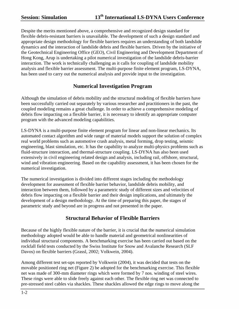
cable direction. The steel cables were supported by the beams of the steel rigs and are anchored to a concrete block on the ground at the ends. To simulate the rockfall scenarios, an 820-mm diameter ball made of steel-fiber-reinforced concrete was adopted as the weight. The total mass of the weight was 825 kg. Tests were performed with the concrete ball dropping at different heights (16 m & 32 m). The performance and the non-linear behavior of different structural components of the flexible barrier were studied in the numerical simulation.
Figure 2: The specifically-built test rig for rock fall tests (after Volkwein, 2004)
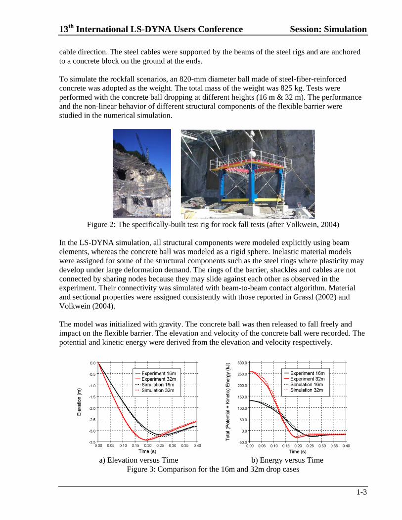
In the LS-DYNA simulation, all structural components were modeled explicitly using beam elements, whereas the concrete ball was modeled as a rigid sphere. Inelastic material models were assigned for some of the structural components such as the steel rings where plasticity may develop under large deformation demand. The rings of the barrier, shackles and cables are not connected by sharing nodes because they may slide against each other as observed in the experiment. Their connectivity was simulated with beam-to-beam contact algorithm. Material and sectional properties were assigned consistently with those reported in Grassl (2002) and Volkwein (2004). The model was initialized with gravity. The concrete ball was then released to fall freely and impact on the flexible barrier. The elevation and velocity of the concrete ball were recorded. The potential and kinetic energy were derived from the elevation and velocity respectively.
a) Elevation versus Time b) Energy versus Time Figure 3: Comparison for the 16m and 32m drop cases
Session: Simulation 13th International LS-DYNA Users Conference
1-4
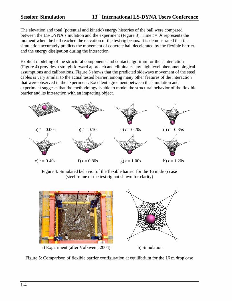
The elevation and total (potential and kinetic) energy histories of the ball were compared between the LS-DYNA simulation and the experiment (Figure 3). Time t = 0s represents the moment when the ball reached the elevation of the test rig beams. It is demonstrated that the simulation accurately predicts the movement of concrete ball decelerated by the flexible barrier, and the energy dissipation during the interaction. Explicit modeling of the structural components and contact algorithm for their interaction (Figure 4) provides a straightforward approach and eliminates any high level phenomenological assumptions and calibrations. Figure 5 shows that the predicted sideways movement of the steel cables is very similar to the actual tested barrier, among many other features of the interaction that were observed in the experiment. Excellent agreement between the simulation and experiment suggests that the methodology is able to model the structural behavior of the flexible barrier and its interaction with an impacting object.
a) t = 0.00s b) t = 0.10s c) t = 0.20s d) t = 0.35s
e) t = 0.40s f) t = 0.80s g) t = 1.00s h) t = 1.20s
Figure 4: Simulated behavior of the flexible barrier for the 16 m drop case
(steel frame of the test rig not shown for clarity)
a) Experiment (after Volkwein, 2004) b) Simulation
Figure 5: Comparison of flexible barrier configuration at equilibrium for the 16 m drop case
13th International LS-DYNA Users Conference Session: Simulation
1-5
Landslide Debris Mobility
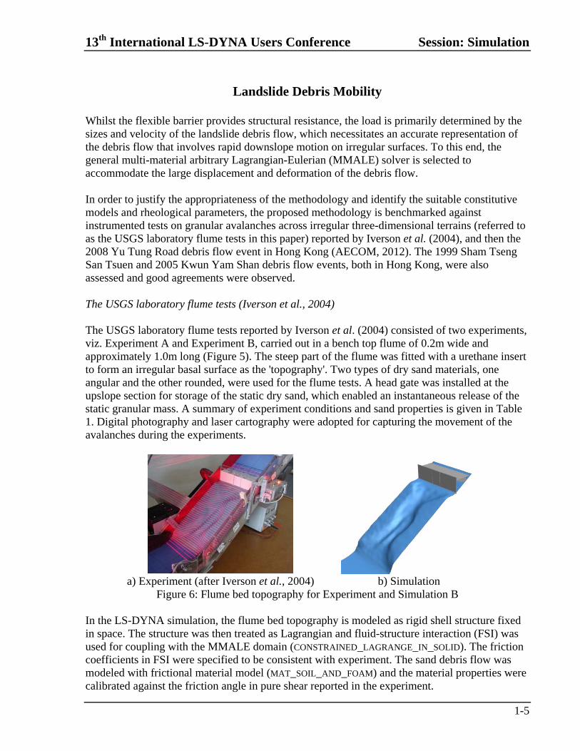
Whilst the flexible barrier provides structural resistance, the load is primarily determined by the sizes and velocity of the landslide debris flow, which necessitates an accurate representation of the debris flow that involves rapid downslope motion on irregular surfaces. To this end, the general multi-material arbitrary Lagrangian-Eulerian (MMALE) solver is selected to accommodate the large displacement and deformation of the debris flow. In order to justify the appropriateness of the methodology and identify the suitable constitutive models and rheological parameters, the proposed methodology is benchmarked against instrumented tests on granular avalanches across irregular three-dimensional terrains (referred to as the USGS laboratory flume tests in this paper) reported by Iverson et al. (2004), and then the 2008 Yu Tung Road debris flow event in Hong Kong (AECOM, 2012). The 1999 Sham Tseng San Tsuen and 2005 Kwun Yam Shan debris flow events, both in Hong Kong, were also assessed and good agreements were observed. The USGS laboratory flume tests (Iverson et al., 2004) The USGS laboratory flume tests reported by Iverson et al. (2004) consisted of two experiments, viz. Experiment A and Experiment B, carried out in a bench top flume of 0.2m wide and approximately 1.0m long (Figure 5). The steep part of the flume was fitted with a urethane insert to form an irregular basal surface as the 'topography'. Two types of dry sand materials, one angular and the other rounded, were used for the flume tests. A head gate was installed at the upslope section for storage of the static dry sand, which enabled an instantaneous release of the static granular mass. A summary of experiment conditions and sand properties is given in Table 1. Digital photography and laser cartography were adopted for capturing the movement of the avalanches during the experiments.
a) Experiment (after Iverson et al., 2004) b) Simulation Figure 6: Flume bed topography for Experiment and Simulation B
In the LS-DYNA simulation, the flume bed topography is modeled as rigid shell structure fixed in space. The structure was then treated as Lagrangian and fluid-structure interaction (FSI) was used for coupling with the MMALE domain (CONSTRAINED_LAGRANGE_IN_SOLID). The friction coefficients in FSI were specified to be consistent with experiment. The sand debris flow was modeled with frictional material model (MAT_SOIL_AND_FOAM) and the material properties were calibrated against the friction angle in pure shear reported in the experiment.
Session: Simulation 13th International LS-DYNA Users Conference
1-6
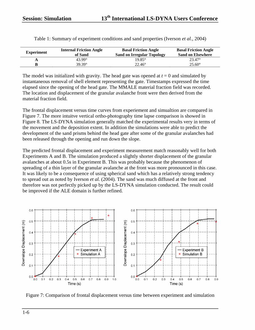
Table 1: Summary of experiment conditions and sand properties (Iverson et al., 2004)
Experiment Internal Friction Angle
of Sand Basal Friction Angle
Sand on Irregular Topology Basal Friction Angle Sand on Elsewhere
A 43.99° 19.85° 23.47° B 39.39° 22.46° 25.60°
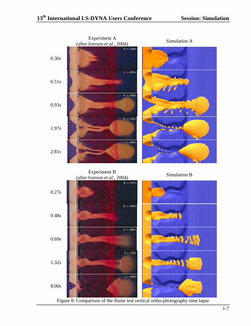
The model was initialized with gravity. The head gate was opened at t = 0 and simulated by instantaneous removal of shell element representing the gate. Timestamps expressed the time elapsed since the opening of the head gate. The MMALE material fraction field was recorded. The location and displacement of the granular avalanche front were then derived from the material fraction field. The frontal displacement versus time curves from experiement and simualtion are compared in Figure 7. The more intuitve vertical ortho-photography time lapse comparison is showed in Figure 8. The LS-DYNA simulation generally matched the experimental results very in terms of the movement and the deposition extent. In addition the simulations were able to predict the development of the sand prisms behind the head gate after some of the granular avalanches had been released through the opening and run down the slope. The predicted frontal displacement and experiment measurement match reasonably well for both Experiments A and B. The simulation produced a slightly shorter displacement of the granular avalanches at about 0.5s in Experiment B. This was probably because the phenomenon of spreading of a thin layer of the granular avalanche at the front was more pronounced in this case. It was likely to be a consequence of using spherical sand which has a relatively strong tendency to spread out as noted by Iverson et al. (2004). The sand was much diffused at the front and therefore was not perfectly picked up by the LS-DYNA simulation conducted. The result could be improved if the ALE domain is further refined.
Figure 7: Comparison of frontal displacement versus time between experiment and simulation
13th International LS-DYNA Users Conference Session: Simulation
1-7
Experiment A
(after Iverson et al., 2004) Simulation A
0.30s
0.51s
0.93s
1.97s
2.81s
Experiment B
(after Iverson et al., 2004) Simulation B
0.27s
0.48s
0.69s
1.32s
8.00s
Figure 8: Comparison of the flume test vertical ortho-photography time lapse
Session: Simulation 13th International LS-DYNA Users Conference
1-8
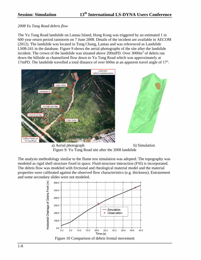
2008 Yu Tung Road debris flow The Yu Tung Road landslide on Lantau Island, Hong Kong was triggered by an estimated 1 in 600 year return period rainstorm on 7 June 2008. Details of the incident are available in AECOM (2012). The landslide was located in Tung Chung, Lantau and was referenced as Landslide LS08-241 in the database. Figure 9 shows the aerial photographs of the site after the landslide incident. The crown of the landslide was situated above 200mPD. Over 3000m3 of debris ran down the hillside as channelized flow down to Yu Tung Road which was approximately at 17mPD. The landslide travelled a total distance of over 600m at an apparent travel angle of 17°.
a) Aerial photograph b) Simulation Figure 9: Yu Tung Road site after the 2008 landslide
The analysis methodology similar to the flume test simulation was adopted. The topography was modeled as rigid shell structure fixed in space. Fluid-structure interaction (FSI) is incorporated. The debris flow was modeled with frictional and rheological material model and the material properties were calibrated against the observed flow characteristics (e.g. thickness). Entrainment and some secondary slides were not modeled.
Figure 10 Comparison of debris frontal movement
13th International LS-DYNA Users Conference Session: Simulation
1-9
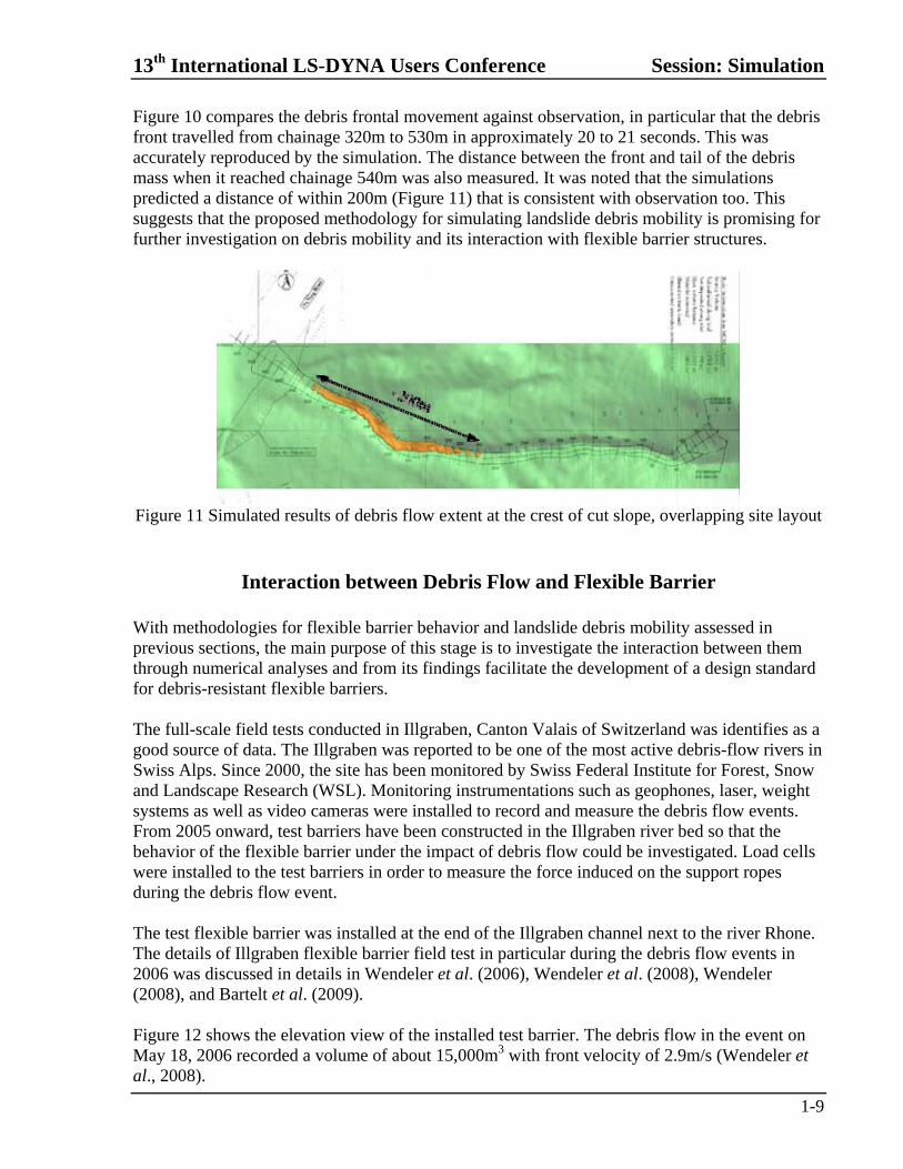
Figure 10 compares the debris frontal movement against observation, in particular that the debris front travelled from chainage 320m to 530m in approximately 20 to 21 seconds. This was accurately reproduced by the simulation. The distance between the front and tail of the debris mass when it reached chainage 540m was also measured. It was noted that the simulations predicted a distance of within 200m (Figure 11) that is consistent with observation too. This suggests that the proposed methodology for simulating landslide debris mobility is promising for further investigation on debris mobility and its interaction with flexible barrier structures.
Figure 11 Simulated results of debris flow extent at the crest of cut slope, overlapping site layout
Interaction between Debris Flow and Flexible Barrier
With methodologies for flexible barrier behavior and landslide debris mobility assessed in previous sections, the main purpose of this stage is to investigate the interaction between them through numerical analyses and from its findings facilitate the development of a design standard for debris-resistant flexible barriers. The full-scale field tests conducted in Illgraben, Canton Valais of Switzerland was identifies as a good source of data. The Illgraben was reported to be one of the most active debris-flow rivers in Swiss Alps. Since 2000, the site has been monitored by Swiss Federal Institute for Forest, Snow and Landscape Research (WSL). Monitoring instrumentations such as geophones, laser, weight systems as well as video cameras were installed to record and measure the debris flow events. From 2005 onward, test barriers have been constructed in the Illgraben river bed so that the behavior of the flexible barrier under the impact of debris flow could be investigated. Load cells were installed to the test barriers in order to measure the force induced on the support ropes during the debris flow event. The test flexible barrier was installed at the end of the Illgraben channel next to the river Rhone. The details of Illgraben flexible barrier field test in particular during the debris flow events in 2006 was discussed in details in Wendeler et al. (2006), Wendeler et al. (2008), Wendeler (2008), and Bartelt et al. (2009). Figure 12 shows the elevation view of the installed test barrier. The debris flow in the event on May 18, 2006 recorded a volume of about 15,000m3 with front velocity of 2.9m/s (Wendeler et al., 2008).
Session: Simulation 13th International LS-DYNA Users Conference
1-10
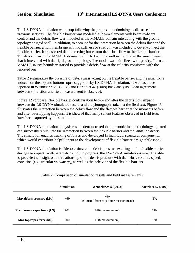
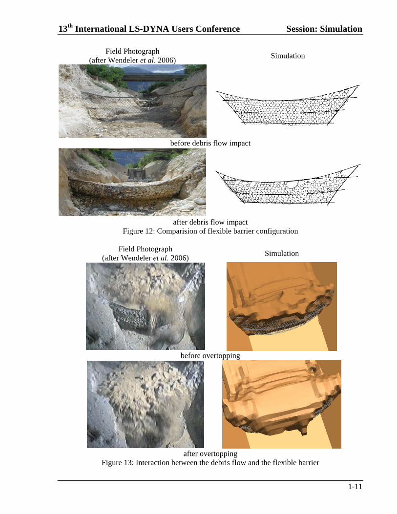
The LS-DYNA simulation was setup following the proposed methodologies discussed in previous sections. The flexible barrier was modeled as beam elements with beam-to-beam contact and the debris flow was modeled in the MMALE domain interacting with the ground topology as rigid shell. In addition, to account for the interaction between the debris flow and the flexible barrier, a null membrane with no stiffness or strength was included to cover/connect the flexible barrier. It transferred the interacting force from the debris flow to the flexible barrier. The debris flow in the MMALE domain interacted with the null membrane in the same manner that it interacted with the rigid ground topology. The model was initialized with gravity. Then an MMALE source boundary started to provide a debris flow at the velocity consistent with the reported one. Table 2 summarizes the pressure of debris mass acting on the flexible barrier and the axial force induced on the top and bottom ropes suggested by LS-DYNA simulation, as well as those reported in Wendeler et al. (2008) and Bartelt et al. (2009) back analysis. Good agreement between simulation and field measurement is observed. Figure 12 compares flexible barrier configuration before and after the debris flow impact, between the LS-DYNA simulated results and the photographs taken at the field test. Figure 13 illustrates the interaction between the debris flow and the flexible barrier at the moments before and after overtopping happens. It is showed that many salient features observed in field tests have been captured by the simulation. The LS-DYNA simulation analysis results demonstrated that the modeling methodology adopted can successfully simulate the interaction between the flexible barrier and the landslide debris. The simulation enables tracking of forces and developed in individual structural components, which would contribute helpful input to the development of flexible barrier design philosophy. The LS-DYNA simulation is able to estimate the debris pressure exerting on the flexible barrier during the impact. With parametric study in progress, the LS-DYNA simulations would be able to provide the insight on the relationship of the debris pressure with the debris volume, speed, condition (e.g. granular vs. watery), as well as the behavior of the flexible barriers.
Table 2: Comparison of simulation results and field measurements
Simulation Wendeler et al. (2008) Bartelt et al. (2009)
Max debris pressure (kPa) ~69 ~60
(estimated from rope force measurement) N/A
Max bottom ropes force (kN) 261 248 (measurement) 240
Max top ropes force (kN) 200 150 (measurement) 170
13th International LS-DYNA Users Conference Session: Simulation
1-11
Field Photograph (after Wendeler et al. 2006)
Simulation
before debris flow impact
after debris flow impact Figure 12: Comparision of flexible barrier configuration
Field Photograph
(after Wendeler et al. 2006) Simulation
before overtopping
after overtopping Figure 13: Interaction between the debris flow and the flexible barrier
Session: Simulation 13th International LS-DYNA Users Conference
1-12
Concluding Remarks
The present study has explored the appropriate numerical analysis methodologies to investigate the interaction of landslide debris flow and flexible barriers. The work indicates that a multi-purpose 3D finite element program, such as LS-DYNA, is capable of modeling the highly non-linear behavior of the structural components of the flexible barrier structures as well as the large deformation of debris mass. It highlights the potential of using such computer programs to obtain a better understanding of the mechanics of the landslide debris as well as its interaction with flexible barrier. It is believed that further findings obtained from the numerical investigation would provide useful insights for the design practice of flexible debris-resistant barriers.
Acknowledgements
This paper is published with the permission of the Head of the Geotechnical Engineering Office and the Director of the Civil Engineering and Development, Government of the Hong Kong Special Administrative Region.
References
AECOM Asia Company Limited (2012). "Detailed Study of the 7 June 2008 Landslides on the Hillside about Yu Tung Road, Tung Chung." Report 271, Geotechnical Engineering Office, Civil Engineering and Development Department, The Government of the Hong Kong SAR. Bartelt, P., Volkwein, A., Wendeler, C., (2009). “Full-scale Testing and Dimensioning of Flexible Debris Flow Barriers.” Summary Report CTI Debris Flows, Swiss Federal Institute of Forest, Snow and Landscape Research. Grassl, H. G. (2002). “Experimentelle und numerische Modellierung des dynamischen Trag- und Verformungsverhaltens von hochflexiblen Schutzsystemen gegen Steinschlag.” Doktorarbeit, Eidgenössische Technische Hochschule Zürich. Iverson, R. M., Logan, M. and Denlinger R. P. (2004). “Granular Avalanches across Irregular Three-Dimensional Terrain: 2. Experimental Tests.” Journal of Geophysical Research, 109, F01015. Volkwein, A. K. H. (2004), “Numerische Simulation von flexiblen Steinschlagschutzsystemen.” Doktorarbeit, Eidgenössische Technische Hochschule Zürich. Wendeler, C. (2008). “Murgangrückhalt in Wildbächen – Grundlagen zu Planung und Berechnung von flexiblen Barrieren.” Doktorarbeit, Eidgenössische Technische Hochschule Zürich. Wendeler, C., McArdell, B. W., Rickenmann, D., Volkwein, A., Roth, A., Denk, M. (2006). “Field Testing and Numerical Modeling of Flexible Debris Flow Barriers.” Proceedings of International Conference on Physical Modelling in Geotechnics, Hong Kong. Wendeler, C., McArdell B.W., Volkwein A., Denk, M. and Groener, E. (2008). “Debris Flow Mitigation with Flexible Ring Net Barriers – Field Tests and Case Studies.” Proceedings of Second International Conference on Monitoring, Simulation, Prevention and Remediation of Dense and Debris Flows, Wessex Institute of Technology, United Kingdom, 21-31