Embed Size (px)
Citation preview

Tennessee Valley Authority, Post Office Box 2000, Spring City, Tennessee 37381-2000
JUL 1 0 10 CFR 50.4
U.S. Nuclear Regulatory Commission ATTN: Document Control Desk Washington, D. C. 20555
Gentlemen:
In the Matter of ) Docket No.50-390 Tennessee Valley Authority
WATTS BAR NUCLEAR PLANT (WBN) UNIT 1 - REACTOR VESSEL FRACTURE TOUGHNESS TESTING (J-R) - SUPPLEMENTAL TESTING OF SURVEILLANCE CAPSULE W SPECIMEN (TAC NO. MB2335)
This letter provides the test results for the unirradiated fracture toughness testing on two modified American Society of Testing and Materials (ASTM) E399 specimens and two standard ASTM E1820 specimens. These Proof-of-Principle test results were developed using ASTM E813 J-R curve analysis and have been certified by the BWXT's Quality Assurance Program. These test results are provided in Enclosure 1.
Revision 2 of the Project Test Plan, "Reactor Vessel Surveillance Program (RVSP) Capsule W M T Specimen Fracture Toughness Testing," is provided in Enclosure 2. Technical Procedure (TP)-177, Revision 9, "Automated, Single-Specimen JIntegral Fracture Toughness Testing," is also provided in Enclosure 3.
TVA requests NRC to review and approve the testing procedure and test plan, and determine the test results are acceptable before the radiated testing begins. The NRC's comments have been incorporated into these documents and a draft of the enclosed test results were provide to the NRC WBN Project Manager for NRC's review on June 13, 2001. Currently, the radiated testing
Pnnted on reycled oapa r

U.S. Nuclear Regulatory Commission Page 2
JUL 1 0 2001
is scheduled for July 18, 2001, at the BWXT Services facility in
Lynchburg, VA. at 9:00 a.m. As with the unirradiated testing, TVA expects that NRC plans to attend to observe the radiated
testing. Kevin Hour, telephone number (804) 522-5715 will be
the contact at BWXT upon arrival.
If you have any questions concerning this matter, please contact
me at (423) 365-1824.
Sincerely,
P. R. Pace Manager, Site Licensing
and Industry Affairs
Enclosures cc (Enclosures):
NRC Resident Inspector Watts Bar Nuclear Plant 1260 Nuclear Plant Road Spring City, Tennessee 37381
Mr. L. Mark Padovan, Senior Project Manager U.S. Nuclear Regulatory Commission MS 08G9 One White Flint North 11555 Rockville Pike Rockville, Maryland 20852-2739
U.S. Nuclear Regulatory Commission Region II Sam Nunn Atlanta Federal Center 61 Forsyth St., SW, Suite 23T85 Atlanta, Georgia 30303

ENCLOSURE 1
PROOF OF PRINCIPLE TEST RESULTS AND
QUALITY ASSURANCE CERTIFICATION OF CONFORMANCE

B VV VT sc.rý: lna-Lyslebburg Tech ý C'v.nter
Quality Assyrance Cerdfluchin of' (A lift, r Ilia nusf,"
w"W"S Com"Id Hary A. OTYTWX.'ý
Amnsaxwo Vv! icy A 40 homb".ý', (KIN! 70264485-Al'i
low, hemby cuslas Tal sho of unhwhowd mg psAwmal in xvUSawn loth A VAs -ýv ikothc,6;101 puldlaw 108r. dowd 9MAT, Awuuhrf-ý'
lots wong VVIS umik"And ill wordsaws VY101 she Neý ý " ý ' Man (AXAM, RaviOnn (h), dum 1 LAwAmb SO the PRQUI 600, MAW SP Oqvu,*'ýý: Evaluvion hum 'A"alus ]WATUOvar plark
1 Nv Z":: lk
D o w....... ... .. ...
INTRODUCTION
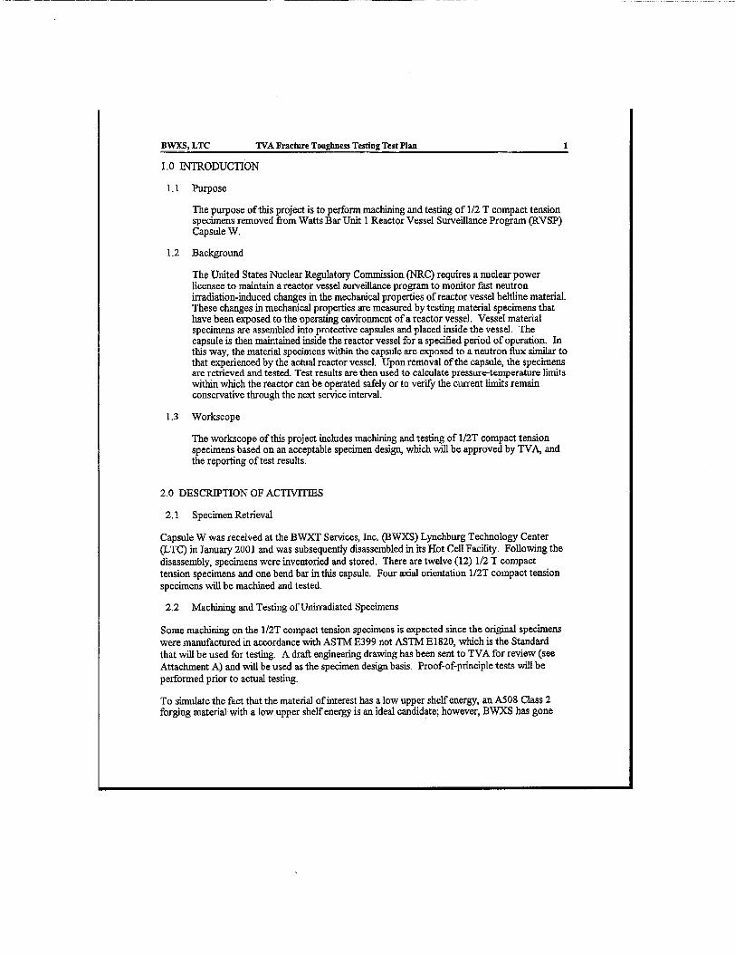
The United States Nuclear Regulatory Commission (NRC) requires a nuclear power licensee to maintain a reactor vessel surveillance program to monitor fast neutron irradiation-induced changes in the mechanical properties of reactor vessel beitline material. These changes in mechanical properties are measured by testing material specimens that have been exposed to the operating environment of a reactor vessel. Vessel material specimens are assembled into protective capsules and placed inside the vessel. The capsule is then maintained inside the reactor vessel for a specified period of operation. In this way, the material specimens within the capsule are exposed to a neutron flux similar to that experienced by the actual reactor vessel. Upon removal of the capsule, the specimens are retrieved and tested- Test results are then used to calculate pressure-temperature limits within which the reactor can be operated safely or to verify the current limits remain conservative through the next service interval.
Capsule W was received at the BWXT Services, Inc. (BWXS) Lynchburg Teclmology Center (LTC) in January 2001 and was subsequently disassembled in its Hot Cell Facility. Following the disassembly, specimens were inventoried and stored. There are twelve (12) 1/2 T compact tension specimens and one bend bar in this capsule. Four axial orientation 1/2T compact tension specimens are to be tested to provide necessary information to demonstrate that Watts Bar Unit 1 Nuclear Power Station reactor vessel has a margin of safety equivalent to that required by Appendix G of the ASME code. This is accomplished by performing generic bounding evaluations as per ASME Section XI, Appendix X criteria and requirements.
Some machining on the 1/2T compact tension specimens is expected since the original specimens were manufactured in accordance with ASTM E399 not ASTM E1820, which is the Standard that will be used for testing. BWXS has proposed a modified E399 specimen design (see Appendix A), where an Electrical Discharge Milling (EDM) cut is made between two pin holes to generate knife edges for mounting of the clip gage. No other changes to the specimen are made. Proof-of-principle tests were proposed prior to actual testing.
To simulate the fact that the material of interest has a low upper shelf energy, BWXS identified a reactor vessel steel weld metal with a low upper shelf energy of 70 ft-lb. A total of four unirradiated specimens (2 BWXS design and 2 ASTM El 820 design) were machined and tested at 390 *F. Specimens were tested in accordance with ASTM E1820 to determine the adequacy of the BWXS design. Representatives from TVA as well as NRC were on site to witness the tests.
SPECIMEN MACHINING AND PREPARATION
A total of five (5) specimens were machined in the BWXS LTC Hot Machine Shop (HMS) using a combination of EDM and CNC milling. One specimen was taken from the base metal and four specimens were taken from the weld. The purpose of manufacturing one base metal specimen was two fold - to practice and to demonstrate that other four specimens were taken from weld using base metal test results as benchmark. Specimen identifications are summarized as follows:
Kevin Hour to Dave Briggs 2 Watts Bar Unit I Fracture Toughness Proof-of-Principle Test

Base metal: lB2 BWXS Design: 2DI and 2D2 ASTM El 820: 2D3 and 2D5
Specimens were machined in accordance with the engineering drawing shown in Attachment A and ASTM E1820 Fig A 2.1 (0.24W pin hole diameter). Specimens were precracked at room temperature in accordance with ASTM E1 820 Section 7.4 to half specimen width. After precracking, a 10% side groove was put on each side of the specimen for a total 20% reduction of thickness to ensure a straight crack front.
SPECIMEN TESTING
All tests were performed per Lynchburg Technology Center Technical Procedure TP177. The tests were performed in displacement control mode on a servohydraulic test machine equipped with a fifty-kip load cell (10,000 pound range was used for the tests). A double cantilever beam clip gage was mounted onto the knife edges for monitoring the
crack mouth opening displacement (CMOD). The CMOD measurements were used to determine the crack length during the test. Force and displacement were monitored continuously through loading and unloading cycles with the load cell and a LVDT interfaced to a personal computer. Crack lengths were calculated based on material compliance relationships using force and CMOD data collected during the unloading portion of each cycle in conjunction with specimen geometry information. All tests were performed in an ATS split type furnace designed to handle both elevated temperature and. sub-zero temperature testing. Temperature was determined by placing a Type K thermocouple onto the specimen surface. The soak time for the compact tension specimen after reaching test temperature was 30 minutes to assure uniform temperature
distribution in the specimen. Temperature control for maintaining sub-zero temperatures was provided by automated control of a solenoid valve, which regulated the flow rate of
liquid nitrogen into the furnace. Test temperatures were controlled to within ± 4 0F of the
test temperature.
Actual dimension measurements were used (nominal dimensions will be used for irradiated specimens due to the concern of radiation exposure) as the input parameters for the JTEST software program. JTEST is certified by BW'XS for the J-integral test. The percent unloading parameter specified the amount of unload for each unloading cycle during the test. An unloading value of 20% from the current force was specified for each specimen.
The force and the CMOD measurements of the unload were used to calculate the crack length using the compliance method. Because the extreme high and low ends of the unload process are relatively noisy, only the middle portion of the unload process was used to calculate the crack length to achieve higher accuracy. A step size of 0.003 inch with a loading displacement rate of 0.01 inch/minute was used.
Kevin Hour to Dave Briggs 3 Watts Bar Unit 1 Fracture Toughness Proof-of-Principle Test

Initially, upon program execution, the specimen was loaded to the final precrack load to determine the initial crack length using the compliance method. The measured crack length was used to check against the known precrack final crack length for consistency. This process was then repeated three times. If the measurements were consistent, the crack length checking process was considered complete. If results were not consistent, the test system was checked and the clip gage was examined for proper seating. This process was continued until reproducible results were obtained. Since the force applied to the specimen was significantly lower than the yield and lower than the forces used in the precracking process, no impact to the test results was expected.
Following the initial crack length measurement cycling, the actual test began. The specimen was loaded and unloaded in accordance with the parameters entered prior to the test. Compliance data (force versus CMOD) during each unloading was used for a crack length calculation. Crack length was calculated using equations that are listed in ASTM E1820.
POST TEST MEASUREM]ENTS
After the test, the specimens were heat-tinted in a furnace between 500 0F to 550 °F for 10 to 15 minutes. The specimens were then removed from the furnace and placed back onto the test fixture and loaded to failure using cyclic loading. The precrack final crack length and test final crack length were measured using a video micrometer system. This system was calibrated prior to and after the measurements were made.
The cracks were measured at nine locations across the crack front spanning the specimen thickness.
These nine measurements were used to determine an average initial and final crack
aAYa 8-(2 ia2+a3+ai+as+a6+a7+a8j
where a AVG is the average crack length from nine measurements a, ...a9 is nine point measured crack length
These values were later used as references to verify the accuracy of the crack length determined from the compliance method.
DATA ANALYSIS AND DISCUSSION
The test data were analyzed by the BWXS certified software JTEST using ASTM E813. The test results are shown in Appendix B. Since only the J-R curve is used to demonstrate that Watts Bar Unit 1 Nuclear Power Station reactor vessel has a margin of
Kevin Hour to Dave Briggs 4 Watts Bar Unit 1 Fracture Toughness Proof-of-Principle Test

safety equivalent to that required by Appendix G of the ASME code, no discussion or comparison are made for J10 determination. Furthermore, comparison will be made at 0.1 inch crack extension as reference for all analyses.
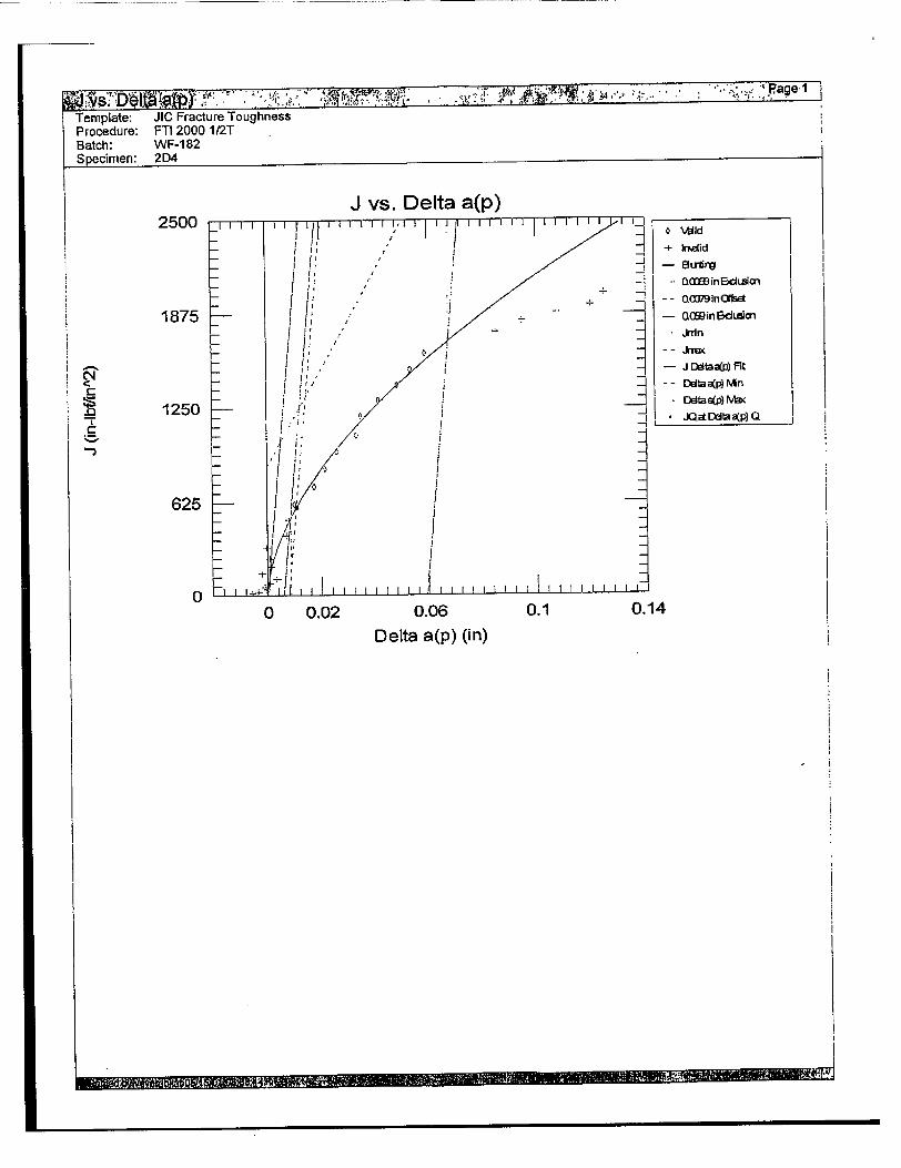
Figures I to 4 show the J-R curve for each specimen. A third power polynomial curve fitting was used to determine the trend curve for the data. Power-law curve fitting was used first however the results were not satisfactory due to a low coefficient of correlation (R2). J and dJ/da values at crack extension of 0. 1 inch were determined and are summarized in Table L
Table 1 J and dJ/da Values at Crack Extension of 0.1 Inch
J at Aa=0.l" dJ/da at ArO.l" Specimen ID (in-lbsFm2)
2D1 (BWXS design) 1,611 4,184
2D2 (BWXS design) 1,910 1,279
2D3 (E1820 design) 1,764 3,242
2D)4 (E1820 design) 1,874 4,568
Figure 5 shows all four J-R curves as well as three J-R curves obtained from tests conducted at 11 0IF, 3500F, and 5500 F by the same laboratory 20 years ago on the same material. Those specimens were designed in accordance with ASTM E813 (ASTM 813 is a predecessor of ASTM E1820). Several observations are drawn from this figure.
1. Normal scatter of weld is observed among four specimens tested. The test data at 390TF are bounded by I 10*F and 550°F test data as expected.
2. Average data of BWXS design are compared to that of El 820 design and the results are summarized in Table 2.
Table 2 Comparison of J and di/da Values at Crack Extension of 0.1 Inch
Specimen Average J at Aa=0.1" Avenge dI/da
Design (in-lbs/in 2 ) Difference (%) at Aa=0.1" Difference (%)
E1820 Design 1819 3905 3.2 30
BWXS Design 1761 2732
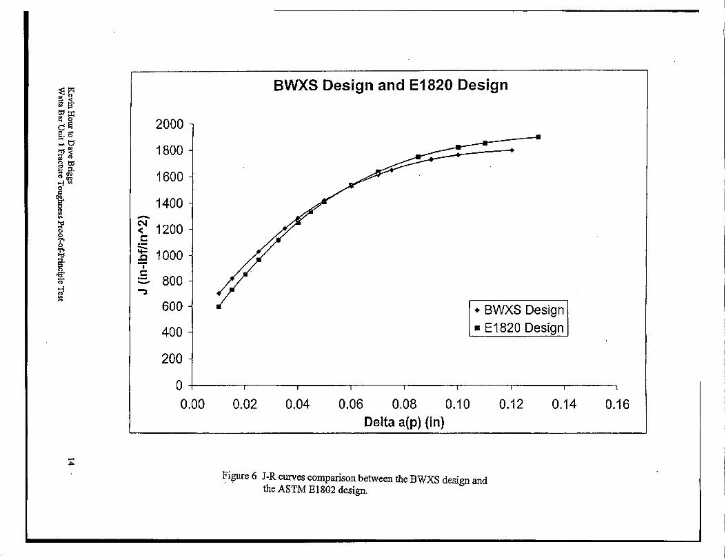
The BWXS design results in lower J and di/da values compared to those of ASTM E1820 design. The trend curve of the average values for BWXS and ASTM E1820
Kevin Hour to Dave Briggs Watts Bar Unit 1 Fracture Toughness Proof-of-Principle Test
5

design are shown in Figure 6. It is concluded that beyond 0.06 inch crack extension, the BWXS design produces conservative results compared to the ASTM E1820 design.
3. It is concluded that there is bias using EWXS design based on the EM values, which are summarized in Table 3. It should be noted that this conclusion is based on a small population.
Table 3 Comparison of E and EM
Specimen ID Input E (ksi) EM (ksi) Average EM (ksi)
2D1 (BWXS design) 25,860 26,150
2D2 (BWXS design) 26,440 27,509*
2D3 (EE1820 design) 28,600 28,745
2D4 (El 820 design) 28,890
* Modulus = 29480 - 5.055 x T (OF) (from ASME Code Section II part D)
Although the difference in EM is close to 10%, the effect on the crack length is less than 3% and is even lower for the J value. Therefore, it is concluded that the bias has a small impact to the test data. This conclusion is consistent with a statement in ASTM E636 "Conducting Supplemental Surveillance Tests for Nuclear Power Reactor Vessels, E706 (LH)" Section 6.1.2.1:
"The pinhole spacings recommended in Test method E399 and Test Method B813 are different. However, this difference does not significantly affect the stress field at the crack tip and therefore either pinhole spacing is acceptable for surveillance testing."
ASTM B636 is now under amendment and the same section reads:
"The pinhole spacings for compact specimens recommended in Test method E399 and Test Method B&1-3 1820 are different. However, this difference does not significantly affect the stress field at the crack tip and therefore either pinhole spacing is acceptable for surveillance testing."
This amendment needs to be approved by ASTM Main Committee before it becomes effective.
4. During the review, it was noticed that the crack extensions determined from the optical measurements were higher than those determined by the compliance method. The BWXS test procedure requires the operator to check the crack length and ensure the measurements are consistent with the final precrack length prior to actual testing. No such problem was noticed at the time of testing. Furthermore, this laboratory usually has
Kevin Hour to Dave Briggs 6 Watts Bar Unit I Fracture Toughness Proof-of-Principle Test
consistent crack length results determined by the compliance method on irradiated specimens. After further examination it was decided that at some point during the test, the stress field at the crack tip did not meet the constraint requirement. This can beea seen by the fact that the crack front was not as straight compared to a test with valid J values. Fractograph of failed specimens are shown in Appendix C. Another approach was to determine the capacity of the specimen. The maximum J-integral capacity of a specimen is given by the smaller of the following:
Jmax = b oVý20, or
J,• =RBoJ20,
where
b = remaining ligment (=W-ap) -y= average of the 0.2% offset yield strength and the ultimate tensile
strength B11 specimen thickness.
Note that 0- = (68+83)/2 = 75.5 ksi1 and B = 0.5 inch were used in the calculation. In the beginning of the test, the Jma, was estimated to be 1,850 in-lbs/in2 and gradually decreased to 1,400 in-lbs/in2 as crack grew by 0.12". All the specimens had J values exceeding the specimen capacity at the end of the test. This explained (1) why compliance crack length under-predicted the actual crack length since the equation assumes the crack tip constraint is met, (2) why the crack front was not straight, and (3) why this laboratory did not have problem with irradiated specimens since they have a higher Dry (-95 ksi) and thus higher capacity. It is expected that the situation will improve when irradiated TVA compact specimens are tested due to higher 01' (-89 ksi).
5. Test data of weld metal specimens were compared to those of base metal specimen (specimen ID was 112, see Appendix B) and found to be consistent with expectations.
'Operator used 90 ksi and 110 ksi for 0.2% offset yield strength and ultimate tensile strength, respectively in the data analysis assuming generic irradiated specimens. The adequate tensile property data were retrieved from a 20-year old report. The impact of oa on J-R curve analysis is small.
Kevin Hour to Dave Briggs 7 Watts Bar Unit 1 Fracture Toughness Proof-of-Principle Test

CONCLUSIONS
It is concluded that the BWXS modified E399 specimen design is adequate for an ASTM E1820 test based on test data presented in this report.
RECOMMENDATIONS
1. BWXS reconmnends that maximum allowable side grooves (25% of specimen thickness) be used on irradiated compact specimen to promote a straight crack front.
2. BWXS shall determine the specimen capacity at 0.1" crack extension for the irradiated specimen and report it as the J value in case of J values exceed specimen capacity. BWXS expects that the specimen capacity should be much higher than the critical J value of 590 in-lbs/in2.
Kevin Hour to Dave Briggs Watts Bar Unit 1 Fracture Toughness Proof-of-Principle Test

2D1
O:
O.
I.1-
1610.81
y =-144170x0 - 46918x2 + 17893x + 434.86 R2 = 0.9991
0.00 0.02 0.04 0.06 0.08 0.10 0.12 0.14 0.16
1Delta a(p) (in)
y= -144170x3- 46918x2 + 17893x + 434.86
y'= -432510x2-93836X+17893
y'(.l)= 4184.3
Figure 1 J-R curve for Specimens 2D1,
1800
1600
1400
1200
1000
800
600
400
200
0
CE
ýo
I

2D2
< 2500.00
,-- 1909.73
n ' 2000.00
o " 1500.00
- y =_.0792E+06X3 350742x2 + 39051x + 432.85
R '2 =0.9934 1000.00
0-00. 0,0
0.00 0.02 0.04 0.06 0.06 0.10 0.12 0.14 0.16
Delta a(p) (in)
y= 1.0792E+06X3 - 350742x2 + 39051X + 432.85
Y= 3.2376E+06x2-701484x+39051
y'(1) 1278.6
Figure 2 J-R curve for Specimens 2D2.0

2D3
1763.907
�. S
��0
15 c�J
H
&
C,
0
H a
0.02 0.04 0.06 0.08
Delta a(p) (in)
0.10 0.12 0.14 0.16
y= 306987x3 - 166798x2 + 27392x + 385.7
y'= 920961x2-333596x+27392
y'(, 1)= 3242.01
Figure 3 J-R curve for Specimens 2D3.
y = 306987x3 _- 166798x2 + 27392x + 385.7 R2 = 0.9947
C4
C
.0
C
2000
1800
1600
1400
1200
1000
800
600
400
200
ri .
0.00

2D4
1874.457
OH
It
to
0
2000
1800
1600
1400
1200
1000
800
600
400
200
0--
0.00
0 I 0.10 0,12 0.14 0.16
y= 739617x3 - 268177x2 + 36015x + 215.11
y'= 2218851x2-536354x+36015
y'(.1)= 4568.11
Figure 4 J-R curve for Specimens 2D4.
S "y = 739617x3 - 268177X2 + 36015X + 215.11 R2 = 0.9924
0.02 0.04 0.06 0.08
Delta. a(p) (in)

J-R Curve Comparison
,110F
390F 390F
5S
O4
0
3000
2500
,2000
# 1500
n n
0 I - 1
0.00 0.05 0.10 0.15 0.20
Delta a(p) (in)
Figure 5 J-R curves comparison between this test program and previous test program.
550F
500 -
* 2D1 2D2 2D3 2D4
- SS033 °SS040 * SS035
IA
I U•V
2000
1800
1600
1400
< 1200
Z 1000 • " = - 8 0 0
400 - Ex
200 (00
0I I I I
0.00 0.02 0.04 0.06 0.08 0.10 Delta a(p) (in)
Figure 6 J-R curves comparison between the BWXS design and the ASTM E 1802 design.
APPENDIX A
BWXS Specimen Design

7
1.1821,+0.005" P.Oo5,,

APPENDIX B
J-integral Test Results

T--ettaa(7771r, aProcedure. FTI 2000 1/2T Batch: WF-182 Specimen: 2D1 __
2000
1500
1000
500
0
J vs. Delta a(p)
0 0.05 0.085 Delta a(p) (in)
+'Mnid
QOXinEc~Ldia, Q0079in~ffis
-J taap)Fit
-~JQ a daap) Q
--4
0.12
____________________________________________________________ -n vtv: 0' 'U.. . .- � . -- '4 'U.. ,j q1
C
n C

"OX6 ...... "ad by. Ste.p Template: JIC Fracture Toughness Procedure: FTI 2000 1/2T Batch: WF-1 82 Specimen: 2D1
• •-:'•,'':" ;StVaid r ' :•lin~sfoh"•,,-elta~ap ( '.,. :.d,."•,T, .''•.O (.i
I Invalid 14.3998 0.00690889 894.888 0.00271519 2 Invalid 26.0598 -0.000235485 1185.40 0.00371799 3 Invalid 41.8246 0.000602247 1473.14 0.00476217 4 Invalid 63.4083 -0.00107645 1779.50 0.00593555 5 Invalid 91.1771 0.000243380 2083.10 0.00720197 6 Invalid 126.884 -0.00173050 2366.38 0.00861311 7 Invalid 173.552 -0.00333500 2628.29 0.0102466 8 Invalid 231.434 -0.000323643 2859.86 0.0120868 9 Invalid 301.151 0.00214581 3042.83 0.0141337 10 Invalid 388.781 0.000730204 3169.67 0.0165322 11 Invalid 490.719 0.00189151 3242.71 0.0192666 12 Valid 600.888 0.00955687 3249.95 0.0223112 13 Valid 724.876 0.0171160 3161.74 0.0257538 14 Valid 847.185 0.0244637 3070-76 0.0292740 15 Valid 961.190 0.0334401 3004.26 0.0327631 16 Valid 1079.21 0.0393156 2905.00 0.0362936 17 Valid 1181.12 0.0499617 2795-41 0.0398705 18 Valid 1287.49 0.0573690 2700.65 0.0434630 19 Invalid 1377.94 0.0685341 2581.08 0.0471280 20 Invalid 1471.83 0.0765046 2464.58 0.0507256 21 Invalid 1553.65 0.0878693 2289.52 0.0546024 22 Invalid 1611.19 0.100636 2169.60 0.0582362 23 Invalid 1654.11 0.116425 1961.46 0.0622114 24 - - - -25 . ....... .
II i • i

Template: JIC Fracture Toughness Procedure: FTI 2000 1/2T Batch: WF-182 Specimen: 201
~~ ebn fl~~e'&t~~8I&Ilatlbhkirr-bfY d) . 4 ~t¾0.0107316 0.0137467 0.0167619 0.0197598 0.0227578 0.0257901 0.0287536 0.0317687 0.0346977 0.0377474 0.0407453 0.0437776 0,0467756 0.0497217 0.0528059 0.0557693 0.0587327 0.0617654 0.0647287 0.0677264 0.0707591 0.0737398 0.0767032
0.00271519 0.00371799 0.00476217 0.00593555 0.00720197 0.00861311 0.0102466 0.0120868 0.0141337 0.0165322 0.0192666 0.0223112 0.0257538 0.0292740 0.0327631 0.0362936 0.0398705 0.0434630 0.0471280 0.0507256 0.0546024 0.0582362 0.0622114
41.6313 40.1484 40.3114 39.9772 40.2378 39.8447 39.5220 40.1220 40.6295 40.3461 40.5769 42.2017 43.8855 45.6052 47.8254 49.3549 52.2924 54.4731 57.9930 60.6935 64.8438 69.9770 77.1229
1.27634 2.32142 3.72147 5.64248 8.10108 11.2572 15.3687 20.4751 26.5879 34.1376 43.0096 53.0160 64.2170 75.3256 86.0775 96.6486 106.992 117.000 126.812 136.039 145.461 153.696 161.970
Valid Valid Valid Valid Valid Valid Valid Valid Valid Valid Valid Valid Valid Valid Valid Valid Valid Valid Valid Valid Valid Valid Valid
Valid Invalid Invalid Invalid Invalid Invalid Invalid Invalid Invalid Invalid Invalid Valid Valid Valid Valid Valid Valid Valid Invalid Invalid Invalid Invalid Invalid
0. . .W � � . . .. r .fJ ..a -.
+ - .. .... = • i I .... .. . i i•l i " t i'l,•

-ol:ta,(ip),..fidiyb~y-Step. .•;•''0 ••.,• ;• ••° "• ,. " . .-. Page 3 . Template: JIC Fracture Toughness " 3 "" Procedure: FTi 2000 1/2T Batch: WF-182 Specimen: 2D1
Invalid Invalid Invalid Valid Valid Valid Valid Valid Valid Valid Valid Valid Valid Valid Valid Valid Valid Valid Valid Valid Valid Valid
Template: JIC Fracture Toughness Procedure: FTI 2000 1/2T Batch: WF-182 Specimen: 2D1
Pane i
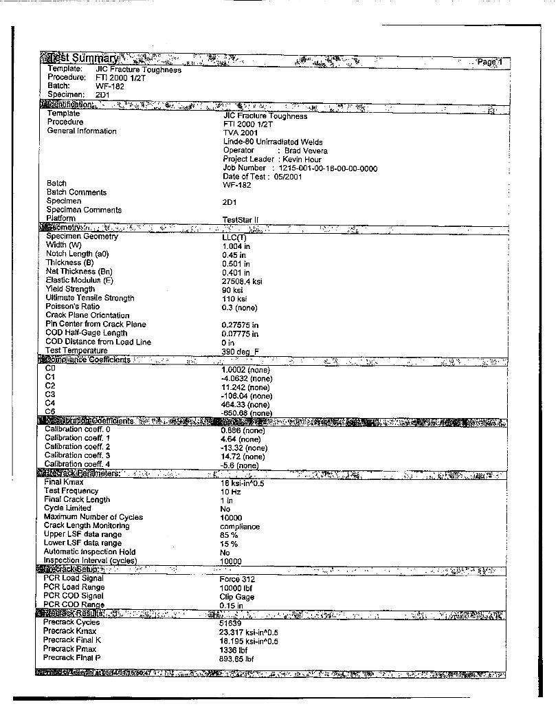
Template JIC Fracture Toughness Procedure FTI 2000 1/2T General Information TVA 2001
Linde-80 Unirradiated Welds Operator : Brad Vevera Project Leader • Kevin Hour Job Number 1215-001-00-18-00-o0-0000 Date of Test: 05/2001
Batch WF-182 Batch Comments Specimen 2D1 Specimen Comments Platform TestStar 11
Specimen Geometry LLC(T) Width (W) 1.004 in Notch Length (a0) 0.45 in
Thickness (B) 0.501 in Net Thickness (Bn) 0.401 in Elastic Modulus (E) 27508.4 ksi Yield Strength 90 ksi Ultimate Tensile Strength 110 ksi Poisson's Ratio 0.3 (none) Crack Plane Orientation Pin Center from Crack Plane 0.27575 in COD Half-Gage Length 0.07775 in COD Distance from Load Line 0 in Test Temperature 390 deg F * cp""e oeffIclInts .... ..."*. * " . " .: ,.- -. " ... " :' Co 1.0002 (none) Cl -4.0632 (none) C2 11.242 (none) C3 -106.04 (none) C4 464.33 (none) C5 -650.68 (none)
Calibration coeff. 0 " 0.886 (none) Calibration coeff. 1 4.64 (none) Calibration S oeff. 2 -13.32 (none) Calibration coeff, 3 14.72 (none) Calibration coeff. 4 e5.1 0non00
Final Kmax 18 ksiFino-r 5 Test Frequency 10 Hz Final Crack Length 1 in Cycle Limited No Maximum Number of Cycles 10000 Crack Length Monitoring compliance Upper LSF data range 85 % Lower LSF data range 15 % Automatic Inspection Hold No Inspection Interval (cycles) 10000
PCR Load Signal Force 312 1 PCR Load Range 10000 Ibf PCR COD Signal Clip GageI PCR COD Range o0-15 in
Precrack Cycles 51639 Precrack Kmax 23.317 ksi-n^0.5 Precrack Final K 18.195 ksi-in^0.5 Precrack Pmax 1336 lbf Precrack Final P 893.85 lbf
b* JV. .N. '0

. .. .... y, .". .. .•. . ; .• , Template: JIC Fracture Toughness Procedure: FTI 2000 112T Batch: WF-182 Specimen: 2D1 Precrack crack length 0.52002 in
Test Control Displacement Ramp Rate 0.00999999 in/Min UnLoad on Load Step No Load Step 300-001 lbf UnLoad on COD Step No COD Step 0.0025 in UnLoad on Displacement Step Yes Displacement Step 0.003 in Unload Pct of Current Load Yes Percent Unload 20 % Unload Absolute No Absolute Unload 2000 lbf Number of Unloads I Crack Propagation Hold Time 2 Sec Unload Rate 100 lbf/Sec Reload Rate 100 lbf/Sec Ramp To Initial Load Yes Pct Of Final Precrack Load 100% Load Ramp Rate 100 lbf/Sec
Load Channel Name Force 312 Maximum Load 5000 Ibf COD Channel Name Clip Gage
Maximum COD 0.15 in Length Channel Name Length 312 Maximum Displacement 1 in Frame Stiffness , 130 kip/in
Event Log Filename elog~txt Data File Name JIC F-T12000 1 2TI WF-182 2D1.RAW
End on maximum load No Maximum Load 5000 Ibif End on maximum COD Yes
Maximum COD 0.15 in End on maximum dispC . No Maximum Displacement I in End on maximum Crack Length No
Maximum Crack Length 1 in End on maximum Crack Extension No Maximum Crack Length Extension I in Termination Type Controlled
Precrack length 1 0.498799 in Precrack length 2 0.508201 in Precrack length 3 0.513098 in Precrack length 4 0.518201 in Precrack length 5 0.51959B in Precrack length 6 0.514701 in Precrack length 7 0.510598 in Precrack length 8 0.508 in Precrack length 9 0.500598 in Average Pracrack: 0.511512 in
Final crack length 6 0.682402 in Final crack length 7 0.672 in Final crack length 3 0.673598 in Final crack length 4 0.663 in Final crack length 5 0.68 in Final crack length 6 0.682402 in ] Final crack length 7 0.677 in Final crack length 8 ,0.6735 in ••
III W30 IIII V.47=ir

Template: JIC Fracture Toughness Procedure: FTI 2000 112T Batch: WF-182 Specimen: 2D1 Final crack length 9 0.637598 in Average Physical Crack: 0.65295 in
Pre Test Normalized Compliance: 41.2437 (none) Calculated Pre Test Crack Length: 0.511512 in Test Termination Normalized Compliance: 77.1229 (none) Calculated Test Term. Crack Length: 0.65295 in
Test Duration: 748.465 Sec Maximum Load: 3320.61 Ibf Maximum COD: 0.0622114 in Maximum Displacement 0.0767547 in Test Terminat Reason J IC h l!shnputs:. - . .- :. - . . . Upper LSF data range: 85 % Lower LSF data range: 15% Blunting Factor M: 2 (none) Minimum J value: 75 in-lbf/in^2 Modulus Factor Lambda: 1 (none) Delta a(p) Offset 0.005 in
Effective Yield Strength Avg. of Yield -Ultimate Front Face Spcm. Displ. Calculated from COD Unload/Reload Compliance Unload -Reload JIC ASTM Standard ASTM E813-89 Number of Dat Point 25 Number of Data Points: 25 Number of Valid Data Points: 7 Delta a(p) Min Limit Line: 0.0086867 in Delta a(p) Max Limit Line: 0.0656909 in
Regression Slope dJQ/da at delta-aQ: 24.0672 ksi cl 4256.86 (none) c2 0.428646 (none)
JQ 614.773 in-lbftin^2 Delta a(Q) 0.0109479 in Kj Value: 130.044 ksi-inA0.5 Unable to parse unload/reload for step: 24 Unable to parse unload/reload for step: 25 A
ASTM E813-89 Section 8.4.2: tp = 106.4 Sec Is tp between 6 Sec
and 600 Sec? Yes ASTM E813-89 Section 7.1.1:
25 JQ/SFS = 0.1537 in Is bO > 25 JQSFS? Yes Is B > 25 JQISFS? Yes
ASTM E813-89 Section 7.2.2: aO/W = 0.5095 Is aO/W between 0.5 -0.75? Yes
ASTM E813-89 Section 7.5: Side grooving = 19.96 pct. Is side grooving -= 25 pct.? Yes
ASTM E813-89 Section 7.6.4: Precrack extension = 0.06151 in Is precrack extension > 0.05a0
and >- 0.05 in? Yes ASTM E813-89 Section 7.6.1:
PL = 4565 Ibf ASTM E813-89 Section 8-4.3.6:
Is the load range of all compliance unloads <- 0.2PL or 0.5 times the current load? Yes
ASTM E813-89 Section 9.3.1: * . I
S,. e ummary: - ,.. . Page Template: JIC Fracture Toughness Procedure: FTI 2000 1/2T Batch: WF-182 Specimen: 2D1
Do all points used for regression lie between Delta a(p) mrin max? Yes
ASTM E813-89 Section 9.2.2: Does at least one data point lie betw
the 0.005906 in -0.05906 in excl. Yes ASTM E813-89 Section 9.4.1.3:
Is the slope of the regression curve at JQ less than SFS? Yes
ASTM E813-89 Section 9.4.1.5: Are all precrack lengths within
7 pct. of the average? Yes Are all final crack lengths within
7 pct. of the average? No ASTM E813-89 Section 9.4.1.6:
Are both near surface crack extensions within 0.02W of the extension at the center? No
ASTM E813-89 Section 9.4.1.7: Is the difference between the crack
extensions found from compliance and the 9-point averages within 15 pct. of either of the 9-point average or Delta a(p) max? No
EM from 9-point precrack front average = 2.586e+004 ksi
Is EM within 10 pct. of nominal E? Yes Is JQ = JIC per ASTM E813-89? No
1%s[RrRXTWW-r-,-nA7 IfF.- " "I zsihý XX - W., XTITIMTRFUMM,

FIGIJ=E 3 - CRACK LENTH NKEASUREMENt RECORD
PROGRAN IDENTIFICATION Project Number: iti-o in- qA Number: 0_0 __ __
Specimen Number: -2o Specimen Size: '11r Operators D Date: 51/tl Procedure: I 1 - 1 Q'ý" n Neasuring Instr.: z-,-!St
WEASUREKENT GUIDE
4 --5 -----
6 --
8--
A 0 B C
A - Load line B - End of Fatigue Crack / Beginning of Crack Extension C - End of Crack Extension D - End of Machined Notch / Beginning of Fatigue Crack
KEASURENENTS
1 9
Edge Average 2 3 4 5 6 7 S
Specimen Mean
Difference A-5 A-C Procedure:
Measure the initial crack length A-B) and final crack length A-C) for each location. Calcul
ate the mean for locations 1 and 9 to determine the Edge Average. Enter these values as indicated, and calculate the Specimen Mean (the mean of the Edge Average and the seven interior locations).
14W
,'115 w .* 4jX5
Initial Crack Length - Specimen Mean Final Crack Length - Specimen Mean
For A-B Dimension For A-C Dimension
Crack Extension - (Final Crack Length - Initial Crack Length) - I ____
Measurements and calcs made: Measuremen alcs checked:
• Date: I,.. 'ate:
3.9L0
A-13;

__P__,._______ ___"_"___.......__' ""_______ ___ .__: ' " "'.Pa g .
Template: JIC Fracture Toughness Procedure: FTI 2000 1/2T Batch: WF-182 Specimen: 2D2
J vs. Delta a(p) 3000 1_1, 1, 1, ,-7 , I I I I , , , , , ,7, -I"
0 'Mid
- + In-did
2250 '- : .- _- - or~O -- ,-- OQ•InF~Wn
J INta~p)Rt
1500 Det22i)Ma
_ - H- -- Jrr•~ v~
J JDeta a(p) Q-bt
IZ- -- - JQ~t1eap) Q
750
0 II- 1 - L I I I I I I I I I
0 0.05 0.1 0.15
Delta a(p) (in)
• l ., V al ,t.o ;llol l: • -: , . . . " - ' . .. ... .. .. ... . . . . .

D�Ia aWL WAIt�iitV b�Steb �* .,iYt.½' "'t�'�4��M ' -4 �Mhs I - .t�rwan - '� i z.-' �4n�i�vt#,� fWflM'.Template: JIC Fracture Toughness Procedure: FTl 2000 1/2T Batch: WF-182 Specimen: 2D2
Ib I
1 Invalid 14.1557 0.00625293 885.583 0.00272553 2 Invalid 26.6243 -0.00462271 1201.59 0.00379553 3 Invalid 45.3334 -0.000622799 1524.15 0.00499992 4 Invalid 68.3857 -0.00129998 1837.74 0.00620433 5 Invalid 98.2808 -0.00349494 2141.34 0.00752244 6 Invalid 135.863 -0.000409799 2427.01 0.00895429 7 Invalid 181.906 -0.000324419 2675.50 0.0105154 8 Invalid 239.415 -0.000559082 2889.15 0.0122935 9 Invalid 307.578 0.00194758 3059.04 0.0142578 10 Invalid 393.005 0.000484177 3187.59 0.0165683 11 Invalid 488.267 0.000996871 3271.67 0.0190754 12 Invalid 596.807 0.00250792 3322.68 0.0218874 13 Valid 708.122 0.00959440 3345.07 0.0248854 14 Valid 833.566 0.0120680 3323-35 0.0280851 15 Valid 959.796 0.0130426 3309.23 0.0312693 16 Valid 1079.01 0.0183016 3279.24 0.0345206 17 Valid 1198.42 0.0254806 3199.64 0.0379632 18 Valid 1321.67 0.0301205 3118.30 0.0414315 19 Valid 1434.59 0.0383882 3013.54 0.0450449 20 Valid 1558.29 0.0412137 2913.28 0.0485701 21 Valid 1663.78 0.0498996 2740.29 0.0524161 22 Valid 1742.42 0.0607746 2588.99 0.0560654 23 Invalid 1809.25 0.0717546 2456.67 0.0596063 24 Invalid 1867.13 0.0844989 2310.54 0.0633795 25 Invalid 1904.90 0.0994371 2139.28 0.0672256 26 Invalid 1932.54 0.114374 1967-31 0.0710248 27 Invalid 1973.95 0.125118 1854.97 0.0747051 28 Invalid 1976,51 0.142033 1646.48 0.0788299 29 ......- -.
- "" " " ]•:'l'" "

Template: J IC Fracture Toug hness Procedure: FTI 2000 1/2T Batch: WF-182 Specimen: 21D2
Invalid Invalid Invalid
Invalid Valid Valid Valid Valid Valid Valid Valid Valid Valid Valid Valid Valid Valid Valid Valid Valid Valid Valid Valid Valid Valid Valid Valid Valid
gm4, W-7.~ r M , .7I

Tempate: JIC Fracture Toughness Procedure, FT1 2000 1/2T Batch: WF-182 Specimen: 2D2
Template JIC Fracture Toughness Procedure FTI20001/2T General Information TVA 2001
Linde-80 Unirradiated Welds Operator Brad Vevera Project Leader Kevin Hour Job Number : 1215-001-00-18-00-00-0000 Date of Test: 05/2001
Batch WF-182 Batch Comments Specimen 2D2 Specimen Comments Platform TestStar 11
Specimen Geometry LLC(I-) Width (W) I in Notch Length (a0) 0.45 in] Thickness (B) 0-5005 in Net Thickness (Bn) 0.4005 in Elastic Modulus (E) 27508.4 ksi ' Yield Strength 90 ksi Ultimate Tensile Strength 110 ksi
Poisson's Ratio 0.3 (none) Crack Plane Orientation Pin Center from Crack Plane 0.275 in COD Half-Gage Length 0.0785 in COD Distance from Load Line 0 in Test Temperature 390 degq F
Go 1.0002 (none) C11 -4.0632 (none) C2 11.242 (none) C3 -106.04 (none) 04 464.33 (none) C5 -650.68 (none)
OR e t-7~V \i.- ~ .*;~
Calibration coeff. 0 0.886 (none) Calibration coeff. 1 4.64 (none)
Calibration coeff. 2 -13.32 (none) Ualibration coef. 3 14.72 (none) lCcalibration coeff. 4 -5.6 (noneý
Final Kmax 18 ksi-in-'0.5 Test Frequency 10 Hz
Final Crack Length 1 in Cycle Limited No Maximum Number of Cycles 10000 Crack Length Monitoring compliance Upper ILSF data range 85 % Lower LSF date range 15 % Automatic Inspection Hold No Ins ection Interval c cles 10000 MP, drackSetupN '" ";: i-. .. :': .i PCR Load Signal Force 312 PCR Load Range 10000 Ibf PCR COD Signal Clip Gage PCR COD Range 0.15 in
Precrack Cycles 49026 Precrack Kmax 24.047 ksi-in^0.5 Precrack Final K 18.061 ksi-inA0.5 Precrack Pmax 1371.5 lbf Precrack Final P 877.66 lbf

Template: JIC Fracture Toughness Procedure: FTI 2000 112T Batch: WF-1 82 Specimen: 2D2 Precrack crack lenth 0.52042 in
9 eutioh Rahamet4r s K- 7 ...."-" . " i '-t ';-%' i½i'" ... . Test Control Displacement Ramp Rate 0.00999999 in/Min UnLoad on Load Step No Load Step 300.001 Ibf UnLoad on COD Step No COD Step 0.0025 in UnLoad on Displacement Step Yes Displacement Step 0.003 in Unload Pet of Current Load Yes Percent Unload 20 % Unload Absolute No Absolute Unload 2000 lbf Number of Unloads I Crack Propagation Hold Time 2 Sec Unload Rate 100 lbf/Sec Reload Rate 100 lbf/Sec Ramp To Initial Load Yes Pct Of Final Precrack Load 100 % Load Ramp Rate 100 lbf/Sec Load Channel Name Force 312 Maximum Load 5000 lbf COD Channel Name Clip Gage Maximum COD 0.15 in Length Channel Name Length 312 Maximum Displacement 1 in Frame Stiffness 130 kip/n
Event Log Filename elog.txt Data File Name JIC FTI 2000 1 2T WF-182 2D2.RAW j-=... . .. ::.; :c:. 4.• . : • • .... n.... 4 ., . .. .; -,. ' .,'t.J ,,. A ........... . ..... . ...
End on maximum load No Maximum Load 5000 lbf End on maximum COD Yes Maximum COD 0.15 in End on maximum displ. No Maximum Displacement 1 in End on maximum Crack Length No Maximum Crack Length 1 in End on maximum Crack Extension No Maximum Crack Length Extension 1 in Termination Tpe Controlled ""ed 'n h:' ' " ..,;K"." .i "' . * :,•..'t ": ,•, • •,•..• Precrack length 1 0.504 in Precrack length 2 0.5105 in Precrack length 3 0.513098 in Precrack length 4 0.517299 in Precrack length 5 0.518598 in Precrack length 6 0.516098 in Precrack length 7 0.515598 in Precrack length 8 0.511098 in Precrack length 9 0.508598 in Average Precrack: 0.513574 in
Final crack length 1 0.679902 in
Final crack length 2 0.682299 in Final crack length 3 0.689402 in Final crack length 4 0.69 in Final crack length 5 0.716598 in Final crack length 6 0.701098 in Final crack length 7 0.691799 in Final crack length 8 0.690598 in
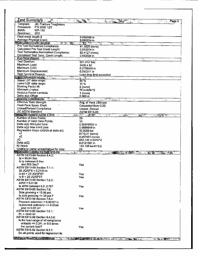
e Pag 3 Template: JIC Fracture Toughness Procedure: FTI 2000 1/2T Batch: WF-1 82 Specimen: 2D2 Final crack length 9 0.688098 in Average Physical Crack: 0.693224 in * cu ~lfed.•_ra~k Ltnn th• .: '•,• •.•; .. ,1'' _• , ".... :-,,' ."'
Pre Test Normalized Compliance: 41.1825 (none) Calculated Pre Test Crack Length: 0.513574 in Test Termination Normalized Compliance: 92.4127 (none) C.alculated Test Term. Crack Len th: 0.693224 in
Test Duration: 921.912 Sec Maximum Load: 3426.4 lbf Maximum COD: 0.0788559 in Maximum Displacement: 0.090211 in Test Terminat Reason Load drop limit exceeded
p• L ,datinge i:85 , Upper LSF data range: 85 % Lower LSF data range: 15 % Blunting Factor M: 2 (none) Minimum J value: 75 in-lbf/in^2 Modulus Factor Lambda: 1 (none) Delta a(p) Offset 0.003 in
Effective Yield Strength Avg. of Yield -Ultimate Front Face Spcm. Displ. Calculated from COD Unload/Reload Compliance Unload -Reload JIC ASTM Standard ASTM E813-89 Number of Data Points: 29 Number of Valid Data Points: 10 Delta a(p) MVa Limit Line: 0.00976803 in Delta a(p) Max Limit Line: 0.0686846 in
Regression Slope dJQ/da at delta-aQ: 32.9089 ksi ci 6719.31 (none) c2 0,467451 (none)
JQ 853.146 in-lbf/in^2 Delta a(Q) 0.0121397 in Kj Value: 153.195 ksi-inA0.5 Unable to parse unload/reload for step: 29
ASTM E813-89 Section 8.4-2: ip = 90.64 Sec Is tp between 6 Sec
and 600 Sec? Yes ASTM E813-89 Section 7.1.1:
25 JQ/SFS = 0.2133 in Is bO > 25 JQ/SFS? Yes Is B > 25 JQ/SFS? Yes
ASTM E813-89 Section 7.2.2: aO/W = 0.5136 Is a0/W between 0.5 -0.75? Yes
ASTM E813-89 Section 7.6: Side grooving = 19.98 pct. Is side grooving <= 25 pct? Yes
ASTM E813-89 Section 7.6.4: Precrack extension = 0.06357 in Is precrack extension >= 0.05a0
and >= 0.05 in? Yes ASTM E813-89 Section 7.6.1:
PL = 4549 lbf ASTM E813-89 Section 8.4.3.6:
Is the load range of all compliance unloads <= 0.2PL or 0.5 times the current load? Yes
ASTM E813-89 Section 9.3.1: Do all points used for regression lie

T• tSu ih'ary. • ...: .,-, . . Page32 Template: JIC Fracture Toughness Procedure: FTI 2000 1/2T Batch: WF-182 Specimen: 2D2
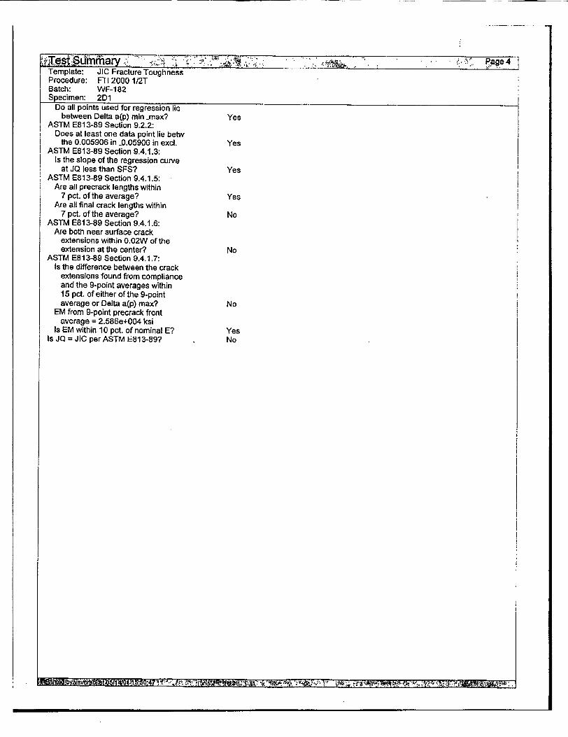
between Delta a(p) mrin max? Yes ASTM E813-89 Section 9.2.2:
Does at least one data point lie betw the 0.005906 in -0.05906 in excl. Yes
ASTM E813-89 Section 9.4.1.3: Is the slope of the regression curve
at JQ less than SFS? Yes ASTIM E813-89 Section 9.4.1.5:
Are all precrack lengths within 7 pct. of the average? Yes
Are all final crack lengths within 7 pct. of the average? Yes
ASTM E813-89 Section 9.4.1.6: Are both near surface crack
extensions within 0.02W of the extension at the center? Yes
ASTM E813-89 Section 9.4.1.7: Is the difference between the crack
extensions found from compliance and the 9-point averages within 15 pct. of either of the 9-point average or Delta a(p) max? No
EM from 9-point precrack front average = 2.644e+004 ksi
Is EM within 10 pct. of nominal E? Yes Is JQ = JIC per ASTM E813-89? No

FIGUR= 3 - CRACK LENGTH NEASURENMENT RECORD
PROGRAM IDENTIFICATION Project Number: CAt '-• _0 (LZ:her: , Specimen Niuber: A.V'1Y- Specimen Size: -Y] Operator; •-• \) - .... Dates: _ I Procedures IT~-V_ 1-1 qk4 Measuring Instr.: i-•,- "
NEASUR•EIDT WUIDE
2--.3
6 --7 6---
g __------ L
A a 6 C
A - Load line B - End of Fatigue Crack / Beginning of Crack Extension C - End of Crack Extension 0 - End of Machined Notch / Beginning of Fatigue Crack
MEASUREMENTS Difference
A-B A-C
1 _.'5,00 L Measure the initial crack length '" 9 Z ,a1- (A-B) and final crack length
(A-C) for each location. CalculEdge Average .*S • s(,$'-4• " ate the mean for locations 1 and
2 9 to determine the Edge Average. 3 L Enter these values as indicated, 4 ,_51 _ . - and calculate the Specimen Mean 5 .-1Jk (the mean of the Edge Average and
Sz l .7 1 the seven interior locations).
8 L ,
Specimen Mean .5-13 5 (-6 V 5;2"
Initial Crack Length - Specimen Mean For A-B Qimension Final Crack Length - Specimen Mean For A-C Dimension
Crack Extension - (Final Crack Length - Initial Crack Length) - * -i
Measurements and calcs made: Measurements and calcs checked:
,-.Date:, ... Date: . . L

Template: JIC Fracture Toughness Procedure: FTI 2000 112T Batch: WF-182 Specimen: 2D3
J vs. Delta a(p) 2500 -1, .IjI, I I,, ,, I 7 ti I
I j• + Inid -iJ S tirg
1875 E / oro
D et -- ea(p)Mtin
1250 -- taa(p) WK -r I _____________
625
0 AI
OI-0 I I I I I 0.I I I II 0 0.05 0.1 0.15
Delta a(p) (in)
I2'.tt. j��tL ... tUxvn *'ca., * .
•?•,�aela•p.e -a.ai 12y•tp c . " ... !. " .. Pagel Template: JIG Fracture Toughness Procedure: FTI 2000 1/2T Batch: WF-182 Specimen: 2D3
~~ . irt ~~~#.2$ L b~ CD(nI
'8 . -4 kt.. � p �.i ,
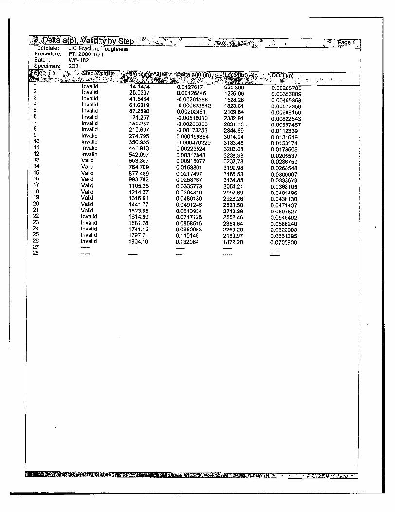
I Invalid 14.1494 0.0127617 920.390 0.00263765 2 Invalid 25.0367 0.00126846 1226.06 0.00356809 3 Invalid 41,5464 -0.00261588 1528.28 0-00465358 4 Invalid 61.6319 -0.000673842 1823.61 0.00572358 5 Invalid 87.2590 0.00202461 2109.64 0.00688150 6 Invalid 121.257 -0.00518010 2382.91 0.00822543 7 Invalid 159.287 -0.00263800 2631.73 • 0.00957457 8 Invalid 210.697 -0.00173253 2844.69 0.0112339 9 Invalid 274.795 0.000159384 3014.94 0.0131619 10 Invalid 350.955 -0.000470229 3133.48 0.0153174 11 Invalid 441.913 0.00223524 3203.08 0.0178503 12 Invalid 542.097 0.00317848 3238.93 0.0205537 13 Valid 653.357 0.00918077 3232.73 0.0236759 14 Valid 764.769 0.0158301 3199.98 0.0268548 15 Valid 877.489 0.0217497 3165.53 0.0300907 16 Valid 993.782 0.0258167 3134.85 0.0333679 17 Valid 1105.25 0.0335773 3054.21 0.0368105 18 Valid 1214.27 0.0394619 2997.69 0.0401496 19 Valid 1316.61 0.0480136 2923.26 0.0436130 20 Valid 1441.77 0.0491246 2828.50 0.0471437 21 Valid 1523.95 0.0613934 2712.36 0.0507827 22 Invalid 1614.69 0.0717126 2552.46 0.0546492 23 Invalid 1681.78 0.0858515 2384.64 0.0586240 24 Invalid 1741.15 0.0980053 2269.20 0.0623098 25 Invalid 1797.71 0.110149 2139.97 0.0661295 26 Invalid 1804.10 0.132084 1872.20 0.0705906 27 ..- -. 2 8 . .. .... .
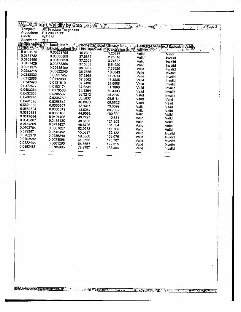
R4ht~a~,Vi~wby Step ,,%..Y4C C , "I• ."'"' *,: ,;.age2 ' Template: JIC Fracture Toughness Procedure: FTI 2000 1/2T Batch: WF-1 82 Specimen: 2D3
0.01 1975•!•c t0 ,, J'Jtosd ,-nergy, for 1 . , aDeltaIa(p) MinMaxJ Exclusion Va!i 0.00263765 40.2308 1.25897 Valid Valid 0.0131782 0.00356809 37.9637 2-25318 Valid Invalid 0.0162450 0.00465358 37.2301 3.74527 Valid Invalid 0.0192429 0.00572358 37.5853 5.54920 Valid Invalid 0.0221375 0.00688150 38.0989 7.83820 Valid Invalid 0.0252215 0.00822543 36.7555 10.8843 Valid Invalid 0.0282022 0.00957457 37.2168 14.3013 Valid Invalid 0.0312863 0,0112339 37.3862 18,8885 Valid Invalid 0.0342498 0.0131619 37.7430 24.6008 Valid Invalid 0.0372477 0.0153174 37.6331 31.3090 Valid Invalid 0.0402284 0.0178503 38.1394 39.4393 Valid Invalid
0.0432606 0:0205537 38.3212 48.2797 Valid Invalid 0.0462244 0.0236759 39.5037 58.5184 Valid Valid 0.0491878 0.0268548 40.8673 68.8825 Valid Valid 0.0521685 0.0300907 42.1314 79.3099 Valid Valid 0.0552524 0.0333679 43.0287 89.7857 Valid Valid 0.0582331 0.0368105 44.8092 100.590 Valid Valid 0.0612654 0.0401496 46.2274 110.854 Valid Valid 0.0642807 0.0436130 48.3806 121.258 Valid Valid 0.0672268 0.0471437 48.6705 131.554 Valid Valid 0.0702764 0.0507827 52.0272 141.805 Valid Valid 0.0732571 0.0546492 55.0897 152.132 Valid Invalid 0.0762378 0.0586240 59.6860 162.079 Valid Invalid 0.0792532 0.0623098 64.0562 170.787 Valid Invalid 0.0822165 0.0661295 68-8651 179.315 Valid Invalid 0.0852488 0.0705906 78,8797 188.304 Valid Invalid
Iffi�Pflnted b�ve�r�bI'�t flRK4/friNAtAA�An -.
we id-f A .. se.r 1 >4 - t t~¶~4t

TeAmlate apTyubyepe Template: JIC Fracture Toughness Procedure: FTI 2000 1/2T Batch: WF-182 Specimen: 2D3
Invalid Invalid Invalid Invalid Valid Valid Valid Valid Valid Valid Valid Valid Valid Valid Valid Valid Valid Valid Valid Valid Valid Valid Valid Valid Valid Valid
15v t. .:._.- .4t•f " 6",. .; .
Procedure: Batch: Specimen:
P., Jage iJIC Fracture Toughness "PTI 2000 1/2T WF-182 2D3
Template JIC Fracture Toughness Procedure FTI 2000 1I2T General Information TVA 2001
Linde-80 Unirradiated Welds Operator : Brad Vevera Project Leader : Kevin Hour Job Number - 1215-001-00-18-00-00-0000 Date of Test: 0512001
Batch WF-182 Batch Comments Specimen 2D3 Specimen Comments Platform TestStar II
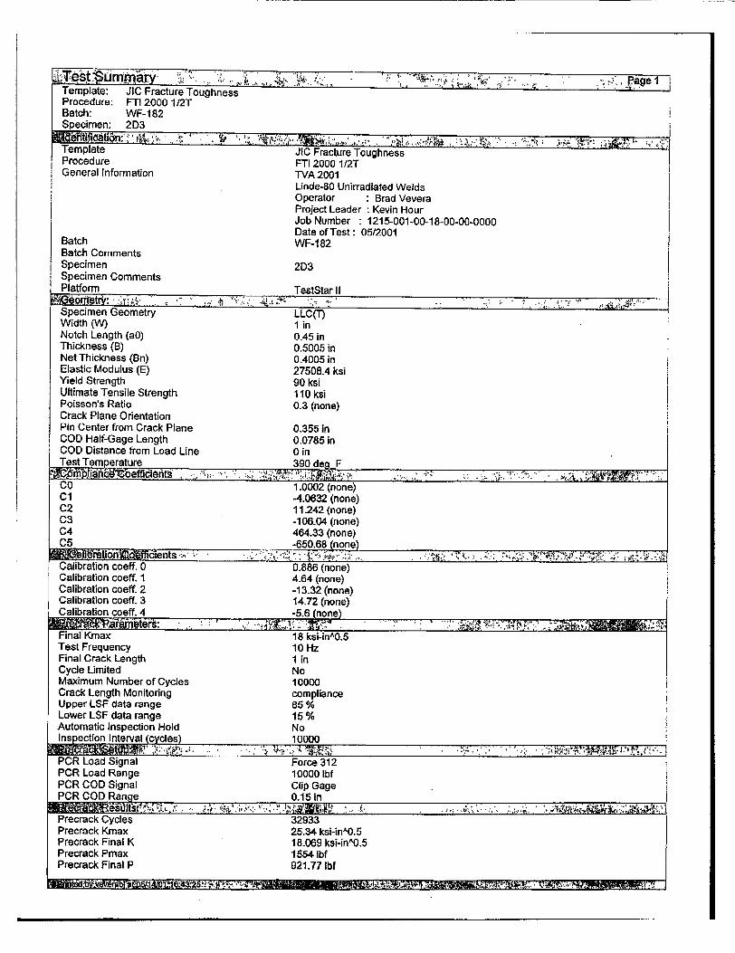
Specimen Geometry LLC(T) Width (W) 1 in Notch Length (ao) 0.45 in Thickness (B) 0.5005 in Net Thickness (Bn) 0.4005 in Elastic Modulus (E) 27508.4 ksi Yield Strength 90 ksi Ultimate Tensile Strength 110 ksi Poisson's Ratio 0.3 (none) Crack Plane Orientation Pin Center from Crack Plane 0.355 in COD Half-Gage Length 0.0785 in COD Distance from Load Line 0 in Test Temperature 390 deg F
ian,, ,effdent . ., 7. . . . CO 1.0002 (none) Cl -4.0632 (none) C2 11.242 (none) C3 -106.04 (none) C4 464.33 (none) C5 -650.68 (none)
Calbraio coRf 0V0..86X(none) Calibration coeff. 0 0.886 (none) Calibration coeff. 1 4.64 (none) Calibration coeff. 2 -13.32 (none) Calibration coeff. 3 14.72 (none) Calibration coeff. 4 -5.6(ne_
Final Kmax 18 ksi-in0.5 Test Frequency 10 Hz
Final Crack Length 1 in Cycle Limited No Maximum Number of Cycles 10000 Crack Length Monitoring compliance Upper LSF data range 85 % Lower LSF data range 15 % Automatic Inspection Hold No Inspection Interval mccles) 10000
S.. .k.... .-:••-.• •,• ., ,.:, , :?. ; . . . ..- ••, . .
PCR Load Signal Force 312 PCR Load Range 10000 Ibf PCR COD Signal Clip Gage PCR COD Range 0.15 in
Precrack Cycles 32933 Precrack Kmax 25.34 ksi-in A0.5
Precrack Final K 18.069 ksi-in^0.5 Precrack Pmax 1554 Ibf Precrack Final P 921.77 Ibf
I"Tamn #-J,

Template: JIC Fracture Toughness Procedure: FTI 2000 1/2T Batch: WF-182 Specimen: 2D3 Precrack crack length 0.50505 in
M eter.s......•,. ..... , Test Control Displacement Ramp Rate 0-00999999 in/Min UnLoad on Load Step No Load Step 300.001 lbf UnLoad on COD Step No COD Step 0.0025 in UnLoad on Displacement Step Yes Displacement Step 0.003 in Unload Pct of Current Load Yes Percent Unload 20% Unload Absolute No Absolute Unload 2000 Ibf Number of Unloads 1 Crack Propagation Hold Time 2 Sec Unload Rate 100 Ibf/Sec Reload Rate 100 lbf/Sec Ramp To Initial Load Yes Pot Of Final Precrack Load 100 % Load Ramp Rate "100 Ibf/Sec
Load Channel Name Force 312 Maximum Load 6000 Ibf COD Channel Name Clip Gage Maximum COD 0.15 in
Length Channel Name Length 312 Maximum Displacement I in Frame Stiffness 130 kip/in
"Event Log Filename elog.txt Data File Name JIC FTI 2000 1 2T WF-182 2D3.RAW
End on maximum load No Maximum Load 5000 Ibf End on maximum COD Yes Maximum COD 0.15 in End on maximum displ. No Maximum Displacement 1 in End on maximum Crack Length No Maximum Crack Length I in End on maximum Crack Extension No Maximum Crack Length Extension 1 in Termination Type Controlled
• lllPrec .track q~ntls • . ... ; .... . .
Precrack length 1 0.491902 in Precrack length 2 0.499 in Precrack length 3 0.5065 in Precrack length 4 0.512 in Precrack length 5 0.516598 in Precrack length 6 0.517 in Precrack length 7 0.519098 in Precrack length 8 0.519098 in Precrack length 9 0.518598 in Average Precrack: 0.511818 in
Final crack length 1 0.614201 in
Final crack length 2 07648902 in Final crack length 3 07668 in Final crack length 4 0.679 in Final crack length 5 0.683902 in Final crack length 6 0.686 in Final crack length 7 0.685 in Final crack length 8 0.676598 in
-i
Template., JIC Fracture Toughness
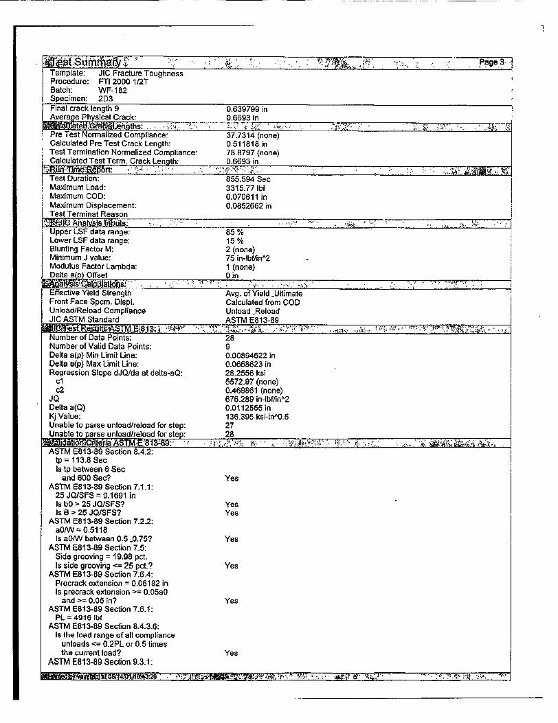
Procedure: FTi 2000:1.2T Batch- WF-1 82 Specimen: 2D3 Final crack length 9 0.639799 in Average Phyical Crack: 0.6693 in
Pre Test Normalized Compliance- 37.7314 (none)
Calculated Pre Test Crack Length: 0.511818 in Test Termination Normalized Compliance: 78.8797 (none) Calculated Test Term. Crack Length: 0.6693 in
Test Duration: 855.594 Sec Maximum Load: 3315.77 Ibf Maximum COD: 0.070611 in Maximum Displacement: 0.0852662 in Test Terminat Reason
K J c.Anat..s.. . . . . .,1 Upper LSF data range: 85 % Lower LSF data range: 15 % Blunting Factor M: 2 (none) Minimum J value: 75 in-lbffin^2 Modulus Factor Lambda: 1 (none) Delta a Offset 0 in
Effective Yield Strength Avg. of Yield -Ultimate Front Face Spcm. Displ. Calculated from COD Unload/Reload Compliance Unload -Reload JIC ASTM Standard ASTM E813-89 I
Number of Data Points: 28 Number of Valid Data Points: 9 Delta a(p) Min Limit Line: 0.00894622 in Delta a(p) Max Limit Line: 0.0668623 in Regression Slope dJQ/da at delta-aQ: 28.2556 ksi
cl 5572.97 (none) c2 0.469861 (none)
JQ 676.289 in-lbf/inA2 Delta a(Q) 0.0112555 in Kj Value: 136.395 ksi-inA0.S Unable to parse unload/reload for step: 27 Unable to parse unload/reload for step: 28
W eT iaASTM-E813-89: . ;. ' .. - ' .-, ,- ..A.,, , , . . . ASTM E813-89 Section 8.4.2:
tp= 113.8 Sec Is tp between 6 Sec
and 600 See? Yes ASTM E813-89 Section 7.1.1:
25 JQ/SFS = 0.1691 in Is bO > 25 JQISFS? Yes Is B > 25 JQ/SFS? Yes
ASTM E813-89 Section 7.2.2: a0/W = 0.5118 Is a0/W between 0.5 -0.75? Yes
ASTM E813-89 Section 7.5: Side grooving = 19.98 pct. Is side grooving <= 25 pct.? Yes
ASTM E813-89 Section 7.6.4: Precrack extension = 0.06182 in Is precrack extension >= 0.05a0
and >= 0.05 in? Yes ASTM E813-89 Section 7.6.1:
PL = 4916 lbf ASTM E813-89 Section 8.4.3.6:
Is the load range of all compliance unloads <= 0.2PL or 0.5 times the current load? Yes
ASTM E813-89 Section 9.3.1: -_ . MSM 261'••1,{•2 . "•'%J...;E•~•.-.• • ; ;•"" :,!' ;-,.• • ''"••:•.. -i,",: ; :.., •'

MOM.* C. . . Pge.4 Template: JIG Fracture Toughness Procedure: FTI 2000 1/2T Batch: WF-182 Specimen: 2D3
Do all points used for regression lie between Delta a(p) min -max? Yes
ASTM E813-89 Section 9-2.2: Does at least one data point lie betw
the 0.005906 in 0.05906 in excl. Yes ASTM E813-89 Section 9.4.1.3:
Is the slope of the regression curve at JQ less than SF5? Yes
ASTM E813-89 Section 9.4.1.5: Are all precrack lengths within
7 pct. of the average? Yes Are all final crack lengths within
7 pct. of the average? No ASTM E813-89 Section 9.4.1.6:
Are both near surface crack extensions within 0.02W of the extension at the center? No
ASTM E813-89 Section 9.4.1.7: Is the difference between the crack
extensions found from compliance and the 9-point averages within 15 pct. of either of the 9-point average or Delta a(p) max? No
EM from 9-point precrack front average = 2.86e+004 ksi
Is EM within 10 pct. of nominal E? Yes Is JO = JIC per ASTM E813-89? No
t�t�bIitQ5l1W11O$4&2S .. A.. .AJ -. . *f' �$�a'\'1�jflVt. .
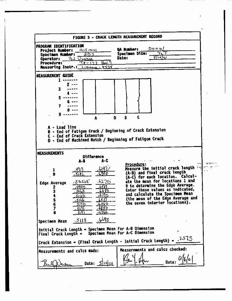
FIGURE 3 - CRACK LEN6TH NEAStaM RECORD
PROGRAM IDENTIFICATION Project Ntuber: -1- is '-i _A Number: OoC o
Specimn Numbers ' r)3 Specimen Size: Operator: Dae1 'l A)E te• Procedure: -'j Measuring Instr.:
NEASUREKE(T WIDE
2 --3
4--5 -t
6--7
A 0 B C
A - Load line B - End of Fatigue Crack / Beginning of Crack Extension C - End of Crack Extension 0 - End of Machined Notch / Beginning of Fatigue Crack
MEASUREMENTS
1 9
Edge Average 2 3 4 5 6 7 B
Specimen Mean
Difference A-9 A-C
7L�
7,5 -)_ "
_. 5~fl
Measure the Initial crack length (A-B) and final crack length (A-C) for each location. Calculate the mean for locations 1 and 9 to determine the Edge Average. Enter these values as indicated, and calculate the Specimen Mean (the mean of the Edge Average and the seven Interior locations).
,511 t _. ____1
Initial Crack Length - Specimen Mean Final Crack Length = Specimen Mean
For A-B Qimension For A-C Dimension
Crack Extension - (Final Crack Length - Initial Crack Length) - ),515
Measurements and calcs made: Measurements and calcs checked:
Date: •4[o) Date: ~'
--4'
%&I
JIC Fracture Toughness FTI 2000 1/2T WF-182 2D4
J vs. Delta a(p)
0 0.02 0.06 0.1
Delta a(p) (in)
o W•d
+ Invlid
-- guarg nrCT .. J
-- Qa179inCrb•t - 0S9 in SdWon
.kyin
J Odtaa(PD Fit
-- Delta a(p Min
- Dt a(p)
JQ Dta(p) Q
0.14
Template: Procedure: Batch: Specimen:
2500
1875
C
1250
625
0
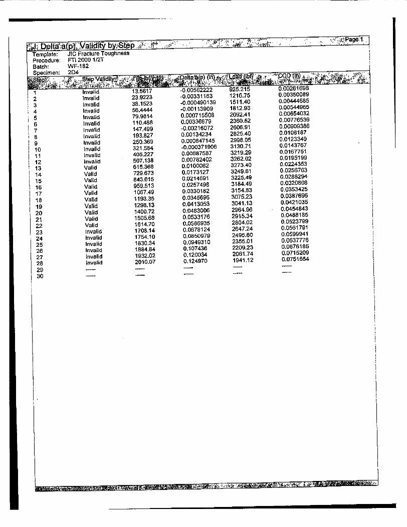
2 Invalid 23.9223 -0.00331163 1215.7b v.uvaOuuou
3 Invalid 38.1523 -0.000490139 1511.40 0.00444685
4 Invalid 56.4444 -0.00113909 1812.93 0.00544965
5 Invalid 79.9814 0.000715508 2092.41 0.00654032
6 Invalid 110.488 0.00336879 2360.52 0.00776539
7 Invalid 147.499 -0.00216072 2606.91 0.00909386 8 Invalid 193.827 0.00134234 2825.40 0.0106187 9 Invalid 250369 0.000847145 2998.05 0.0123349
10 Invalid 321.584 -0.000371906 3130.71 0.0143767
11 Invalid 405.227 0.00687587 3219.29 0.0167751 12 Invalid 507.138 0.00782402 3262.02 0.0195199
13 Valid 615.368 0.0100062 3273.40 0.0224353
14 Valid 729.673 0.0173127 3249.61 0.0256763
15 Valid 843.615 0.0214691 3225.49 0.0288294
16 Valid 959.513 0.0257498 3184.49 0.0320808
17 Valid 1067.49 0.0330182 3154.83 0.0353425
18 Valid 1193.35 0.0345696 3075.23 0.0387696
19 Valid 1298.13 0.0413053 3041.13 0.0421035
20 Valid 1400.72 0.0483006 2964.96 0.0454843
21 Valid 1505.68 0.0533176 2915.34 0.0488185
22 Valid 1614.70 0.0586935 2804.02 0.0523799
23 invalid 1708.14 0.0678124 2647.24 0.0561791
24 Invalid 1754.10 0.0850979 2495.60 0.0599941
25 Invalid 1830.34 0.0949310 2355.01 0.0637776
26 Invalid 1884.84 0.107436 2209.23 0.0676185
27 Invalid 1932.02 0.120034 2061.74 0.0715209
28 Invalid 2010.07 0.124970 1941.12 0.0751654
2 9 ..... 30 -

ej"ta... " "V- i" y by.-Step .3 ' .¶" "h, ' Page 27
Template: JIC Fracture Toughness Procedure: FTI 2000 1/2T Batch: WF-182 Specimen: 2D4
U 117'04 Jlery na•do, "." , ". for "' "i ira Jxci usion'VAlidity
0.01 07661 01.00261698 35.5163 1.23774 Valid Invalid 0.0137467 0.00350089 35.9174 2.18111 Valid Invalid 0.0167102 0.00444685 36.4255 3.47021 Valid Invalid 0.0197426 0.00544965 36.3166 5.13241 Valid Invalid 0-0227750 0.00654032 36.6452 7,25680 Valid Invalid
0.0257901 0.00776539 37.1347 9.99622 Valid Invalid
0.0287019 0.00909386 36.1323 13.3200 Valid Invalid 0.0317687 0.0106187 36.7601 17.5004 Valid Invalid
0.0347322 0.0123349 36.6782 22.5466 Valid Invalid 0.0377129 0.0143767 36.4557 28.8739 Valid Invalid
0.0407106 0.0167751 37.7939 36.5840 Valid Invalid 0.0437433 0.0195199 37.9747 45.5979 Valid Invalid
0.0467929 0.0224353 38.3947 55.2598 Valid Valid 0.0497390 0.0256763 39.8435 65-9921 Valid Valid
0.0528059 0.0288294 40.6983 76.3411 Valid Valid 0.0557520 0.0320808 41.6028 86.9094 Valid Valid 0.0587673 0.0353425 43.1975 97.3977 Valid Valid
1 0.0617480 0.0387696 43.5480 108.225 Valid Valid 0.0647976 0.0421035 45.1118 118.578 Valid Valid 0.0677610 0.0454843 46.8131 128.850 Valid Valid 0.0707933 0.0488185 48.0845 138.800 Valid Valid 0.0737913 0.0523799 49.4969 149.207 Valid Valid 0.0768063 0.0561791 52.0190 159.714 Valid Invalid 0.0797528 0.0599941 57.2835 169.673 Valid Invalid 0.0827677 0.0637776 60.5975 179.033 Valid Invalid 0.0857658 0.0676185 65.1944 187.927 Valid Invalid 0.0887811 0.0715209 70.3149 196.376 Valid Invalid
0.0918134 0.0751654 72.4712 203.765 Valid Invalid
B, ,V .

Valid Valid Valid Valid Valid Valid Valid Valid Valid Valid
* Valid Valid Valid Valid Valid Valid Valid Valid Valid Valid Valid Valid Valid Valid Valid Valid Valid
Template: JIC Fracture Toughness
Procedure: FTI 2000 1/2T
Batch: WF-1 82 Specimen: 2D4
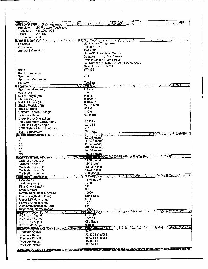
Template JIC Fracture Toughness Procedure FTI 2000 112T General Information TVA 2001
Linde-80 Unirradiated Welds Operator - Brad Vevera Project Leader : Kevin Hour Job Number : 1215-001-00-18-00-00-0000 Date of Test: 05/2001
Batch WF-182 Batch Comments Specimen 2D4 Specimen Comments Platform TestStar II
Jx',( tom tr :-..,!! . " - ,. : •. . .. . .. .,. ,..•:•' • .. s
Specimen Geometry LLC(T) Width (W) I in Notch Length (aO) 0.45 in Thickness (B) 0.5005 in Net Thickness (Bn) 0.4005 in Elastic Modulus (E) 27508.4 ksi Yield Strength 90 ksi Ultimate Tensile Strength 110 ksi Poisson's Ratio 0.3 (none) Crack Plane Orientation Pin Center from Crack Plane 0.355 in COD Half-Gage Length 0.0775 in COD Distance from Load Line 0 in Test Temperature 390 deg F Te tT mp rt r .. ... -. ,- ,.:q*: >f F "._*: •.,". ":; ,,'. ,•, :I
Co 1.0002 (none) Cl -4.0632 (none) C2 11.242 (none) C3 -106.04 (none) C4 464.33 (none) C5 -650.68 (none)
Calibration coeff. 0 0.886 (none) Calibration coeff. 1 4.86 (none) Calibration coeff. 2 -13-32 (none) Calibration coeff. 3 '14.72 (none) Calibration coeff. 4 -5.6 (none)
C a c .. *1, .e.s " Final Kmax 18 ksi-in^0.5 Test Frequency 10 Hz Final Crack Length 1 in Cycle Limited No Maximum Number of Cycles 10000 Crack Length Monitoring compliance Upper LSF data range 85 % Lower LSF data range 15 % Automatic Inspection Hold No Inspection Interval ýcycles) 10000
PCR Load Signal Force 312 PCR Load Range 10000 lbf PCR COD Signal Clip Gage PCR COD Range 0.15 in
Precrack Cycles 34876 Precrack Kmax 26.439 ksi-inA0.5 Precrack Final K 18.061 ksi-in^0.5 Precrack Pmax 1598.2 lbf Precrack Final P 920.39 Ibf
I. 7V7RE01-11 1.i

M T: .,".••," " .. " ' " -' Page2
Template: JIC Fracture Toughness Procedure: FTI 2000 1/23 Batch: WF-182 Specimen: 2134
Precrack crack length 0.50506 in
Test Control Displacement Ramp Rate 0.00999999 in/Min UnLoad oc oad Step No Load Step 300U001 lbf UnLoad on COD Step No COD Step 0.0025 in UnLoad on Displacement Step Yes Displacement Step 0.003 in Unload Pct of Current Load Yes Percent Unload 20 % Unload Absolute No Absolute Unload 2000 Ibf Number of Unloads 1 Crack Propagation Hold Time 2 Sec Unload Rate 100 lbf/Sec Reload Rate 100 Ibf/Sec Ramp To Initial Load Yes Pct Of Final Precrack Load 100 % Load Ramp Rate 100 lbf/Sec
Load Channel Name Force 312 Maximum Load 5000 lbf COD Channel Name Clip Gage Maximum COD 0.15 in Length Channel Name Length 312 Maximum Displacement I in Frame Stiffness 130 kip/in
Event Log Filename elog.txt Data File Name JIC FTI 2000 1 2T WF-182 2D4.RAW
End on maximum load No Maximum Load 5000 Ibf End on maximum COD Yes Maximum COD 0.15 in End on maximum displ. No Maximum Displacement I in End on maximum Crack Length No Maximum Crack Length 1 in i End on maximum Crack Extension No Maximum Crack Length Extension I in Termination Type Controlled
Precrack length 1 0.525598 in Precrack length 2 0.529098 in Precrack length 3 0.526098 in
Precrack length 4 0.522299 in Precrack length 5 0.518799 in Precrack length 6 0.612598 in Precrack length 7 0.5045 in Precrack length 8 0.498201 in Precrack length 9 0.487902 in
Average Precrack: 7 0.514793 in
Final crack length 1 0.676598 in Final crack length 2 0.687598 in Final crack length 3 0.6865 in Final crack length 4 0.6815 in Final crack length 5 0.6715 in Final crack length 6 0.664098 in Final crack length 7 0.642299 in Final crack length 8 0.635598 in

ti ouI0 ted .raecK Lengims: . ,-- ..... ....... - . Pre Test Normalized Compliance: 37.9315 (none) Calculated Pre Test Crack Length: 0.514793 in
i Test Termination Normalized Compliance: 72.4712 (none) Calculated Test Term. Crack Length: 0.663124 in
[R&-U'n4 4e Report: --- ,.
Test Duration: 925-557 Sec
Maximum Load: 3352.31 Ibf
Maximum COD: 0.0751654 in
Maximum Displacement: 0.0918134 in
Test Terminat Reason ... . . .
Upper LSF data range: 85 % Lower LSF data range: 15% Blunting Factor M: 2 (none) Minimum J value: 0 in-lbffinbn2 Modulus Factor Lambda: 1 (none)
Delta a(p) Offset 0.0075 in
Effective Yield Strength Avg. of Yield -Ultimate
Front Face Spore. Displ. Calculated from COD
UnloadbReload Compliance Unload sReload JI ASTM Standard ASTM E8 13-89
Number of Valid Data Points: 10
Delta a(p) Min Limit Line: 0.00849566 in
Delta a(p) Max Limit Line: 0.0675292 in
Regression Slope dJQdda at delta-aQ: 31.3983 ksi cl 7927.07 (none)
c2 0.572339 (none)
jQ 595.549 in-lbf0in472
Delta a(Q) 0.0108518 in K4 Value: 127.995 ks~n^0.5
Unable to parse unload/reload for step: 29 Unable to arse unload/reload for step: 30
ASTM 813-8 STection7.6.:
ASTM E813-89 Section 8.4.2.: tp = 114 Sec
Is tp between 6 Sec and 600 Sec? Yes
ASTM E813-89 Section 7.t1.1: 25 JQ/SFS = 0.1489 in
Is bo > 25 JQoSFS? Yes is B > 25 JQ/SFS? Yes
ASTM E813-89 Section 7.2.2: a0/W = 0.5148 is a0/W between 0.5 -0-76? Yes
ASTM E813-89 Section 7.5: Side grooving = 19.98 pct. Is side grooving <= 25 pct? Yes
ASTM E813-89 Section 7.6-4: Precrack extension = 0-06479 in Is precrack extension >- 0.05a0
and >= 0.05 in? Yes
ASTM E813-89 Section 7.6.1: PL = 4893 Ibf
ASTM E813-89 Section 8.4.3.6: Is the load range of all compliance
unloads <= 0.2PL or 0.5 times the current load? Yes
ASTM E813-89 Section 9.3.1:
ism

•"irn "m ..a . ; " , , .~. y... i - ..... "•:" ' i... "Page4 ____m ary____________ 'K..: , C• ::• - '. ' ...
Template: JIC Fracture Toughness Procedure: FTI 2000 1/2T Batch: WF-182 Specimen: 2D4
Do all points used for regression lie between Delta a(p) min _max? Yes
ASTM E813-89 Section 9.2.2: Does at least one data point lie betw
the 0-005906 in 0.05906 in excl. Yes ASTM E813-89 Section 9.4.1.3:
Is the slope of the regression curve at JQ less than SFS? Yes
ASTM E813-89 Section 9.4.1.5: Are all precrack lengths within
7 pct. of the average? Yes Are all final crack lengths within
7 pct. of the average? No ASTM E813-89 Section 9.4.1.6:
Are both near surface crack extensions within 0.02W of the extension at the center? No
ASTM E813-89 Section 9.4.1.7: Is the difference between the crack
extensions found from compliance and the 9-point averages within 15 pct. of either of the 9-point average or Delta a(p) max? No
EM from 9-point precrack front average = 2.889e+004 ksi
Is EM within 10 pct. of nominal E? Yes Is JQ = JIC per ASTM E813-89? No
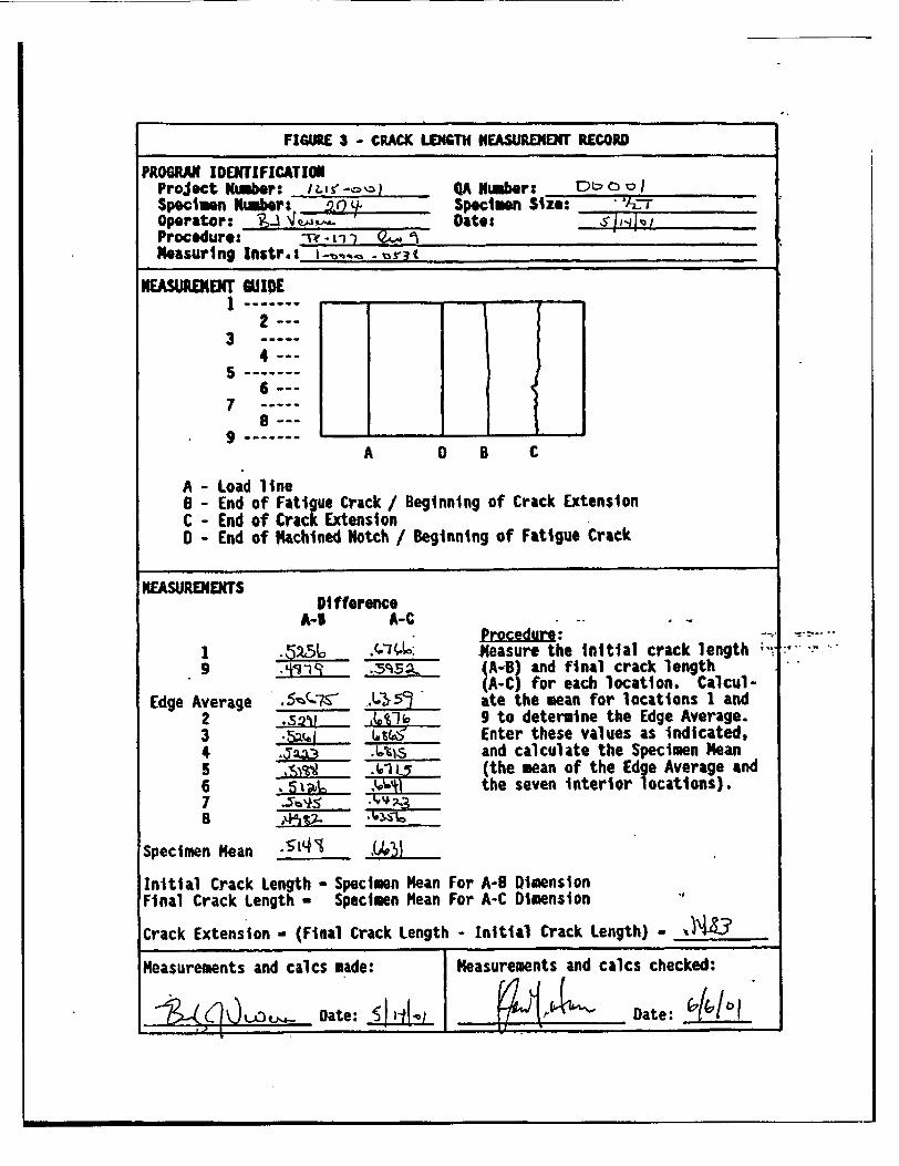
FUMRE 3 - CRACK LENGTH HEASUREMENT RECORD
PROGRAM IDENTIFICATION Project Nimber. sý.4-o QA Number; _D_ _ _.
Specimen Namber: specimen Size: Operator: -i Date: Procedure: -r. I "-iMeasuring Instr.s i t , i
NEASURENENT WIDE
2 --3
4--
7 a--9
A 0 B C
A - Load line B - End of Fatigue Crack / Beginning of Crack Extension C - End of Crack Extension o - End of 1achined Notch / Beginning of Fatigue Crack
NEASUREMENTS Difference
A-I A-C -Procedure:
1 .52(0 _ Measure the initial crack length 9 -413 -1 Ci 4A-4) and final crack length
(AC for each location. CalculEdge Average .-5-7 .L, " ate the mean for locations 1 and
2 .s2% ,.%-4a 9 to determine the Edge Average. 3 ,5x4j ______ Enter these values as indicated, 4 a3 .0%s and calculate the Specimen Mean
,5 ..-1L5 (the mean of the Edge Average and 6 -____ the seven interior locations).
Specimen Mean -',•
Initial Crack Length Specimen Mean For A-0 imension Final Crack Length - Specimen Mean For A-C Dimension
Crack Extension - (Final Crack Length - Initial Crack Length) - •4 .3
Measurements and calcs made: Measurements and calcs checked:
Date: i~ Li.~ Date: 1ii

:" " • " .• U• -" ' " " ,... .,':-,Pa g e l1 STemplate: JIC Fracture Toughness Procedure: FTI 2000 112T Batch: WF-182 Specimen: 162
J vs. Delta a(p)
0.04
Delta a(p) (in)
0
II
-j
-1
,t!II A !
r
F
F"
0.07
70 V~Md4-I indid
aCirtWg QOOSin E'dwuime
-. - Q.59inOEfsd
Jrrin
- J1l6"p) Fit
-- Jdta(p) ?n - - a(p) MEn I a• et~(P) Q
0.1
i 4 m d 5- B' k -- - I ,1k~
3000
2250
'C C
.0
C
I/ J ] |iJ II[' i I- I I I I ,l
/ -'
"' II / /a / ."
A .f
[A,,i: ,/r
"I/I j; ,H+ I
eI.'F Ii i i'
1500
750
0 I I .1
I I I I
/
Template: JIC Fracture Toughness Procedure: FTI 2000 1/2T Batch: WF-182 Specimen: 1 B2
4 ..• .::; '': : V ; d 'i-":' ' " ^ % ,• " • •,, , ...4 ,, ;" h . .," , ..* '.. .. ..
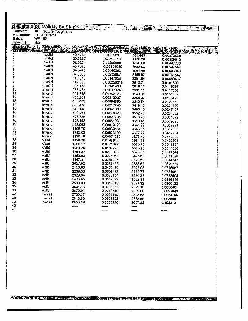
1 Invalid 12.4761 0-0107231 881.449 0.00272036 2 Invalid 20.9367 -0.00476762 1133.36 0.00359910 3 Invalid 32.0264 0.00299566 1390.09 0.00447783 4 Invalid 46.7323 -0.00138050 1653.03 0.00547547 5 Invalid 64.5428 0.00446282 1901.49 0.00648346 6 Invalid 87.0360 0.00212857 2158.92 0.00761547 7 Invalid 113.675 0.00147658 2391.54 0.00880437 R 1I 1.rJari'v A -4A~fA flY
9 10 11 12 13 14 15 16 17 18 19 20 21 22 23 24 25 26 27 28 29 30 31 32 33 34 35 36 37 38 39 40 41
Invalid Invalid Invalid Invalid Invalid Invalid Invalid Invalid Invalid Invalid Invalid Invalid Invalid Invalid Valid Valid Valid Valid Valid Valid Valid Valid Valid Valid Valid Valid Valid Valid Invalid Invalid Invalid
186.458 233.465 291.845 359.201 435.463 520.438 612.138 700.464 798.726 898.193 998.903 1106.70 1215.02 1326-19 1428.26 1539.17 1654.29 1754.27 1863.92 1947.31 2057.52 2150.86 2239.30 2329.94 2436.85 2503.03 2591.48 2670.01 2736.37 2818-63 2859.09
U.ULRUUCOL I0
0.00145480 0.000370243 0.00162128 0.00312907 0.00594650 0.00317243 0.00141606 0.00579320 0.00521705 0.00661933 0.00810128 0.00830564 0.00923100 0.00971269 0.0148642 0.0171077 0.0192729 0.0240936 0.0275954 0.0351298 0.0381425 0.0450420 0.0508482 0.0538754 0.0547693 0-0618813 0.0665877 0.0713449 0.0769149 0.0802203 0.0883226
ZIOI U. t1
2818.16 2991.15 3140.38 3258.92 3349.54 3419.16 3480.15 3532.20 3573.20 3610.41 3641.77 3663.15 3677.27 3673.49 3654.18 3623.18 3573,20 3548.05 3475.68 3422.60 3353.68 3228.93 3152.77 3130.37 3092.81 3034.22 2929.13 2862.60 2803.68 2738.55 2657.22
U.U101U90 0.0116267 0-0132602 0.0151882 0.0173179 0.0196646 0.0221200 0.0247407 0.0274028 0.0301372 0.0329596 0.0357974 0.0387386 0.0417264 0.0447555 0.0479398 0.0511287 0.0544630 0.0577248 0.0611520 0.0644547 0.0679335 0.0716657 0.0751961 0.0783598 0.0816319 0.0850122 0.0886461 0.0921043 0.0954795 0.0988551 0.102313
•a, n�.

Template: JIC Fracture Toughness -------;
Procedure: FTI 2000 1/2T Batch: WF-182 Specimen: 1 B2
Template JlC Fracture Toughness Procedure FTI 2000 1/2T General Information TVA 2001
Linde-80 Unirradiated Welds Operator : Brad Vevera Project Leader Kevin Hour Job Number 1215-001-00-18-00-00-0000 Date of Test: 05/2001
Batch WF-182 Batch Comments Specimen 1B2 Specimen Comments Platform TestStar II
Specimen Geometry LLC(T) Width (W) 1 in Notch Length (aO) 0.45 in Thickness (B) 0.4975 in Net Thickness (Bn) 0.4875 in Elastic Modulus (E) 27508.6 ksi Yield Strength 90 ksi Ultimate Tensile Strength 110 ksi Poisson's Ratio 0.3 (none) Crack Plane Orientation Pin Center from Crack Plane 0.27475 in COD Half-Gage Length 0.078 in COD Distance from Load Line 0 in Test Temrerature 390 deg F
CO 1.0002 (none) Cl -4.0632 (none) C2 11.242 (none) C3 -106.04 (none) C4 464.33 (none) C5 -650.68 4none) Calibration coeff. 0 0.886 (none) Calibration coeff. 1 4.64 (none) Calibration coeff. 2 -13.32 (none) Calibration coeff. 3 14.72 (none) Calibration coeff. 4 -5.6 (none)
ýr bk-.al !m eters:.,.. .' . " "" - - . . ; Final Kmax 18 ksi-inA0.5 Test Frequency 10 Hz Final Crack Length I in Cycle Limited No Maximum Number of Cycles 10000 Crack Length Monitoring compliance Upper LSF data range 85 % Lower LSF data range 15 % Automatic Inspection Hold No Ins ection Interval (ycles) 10000
PCR Load Signal Force 312 PCR Load Range 10000 lbf PCR COD Signal Clip Gage PCR COD Range 0.15 in
Precrack Cycles 60021 Precrack Kmax 24.267 ksi-inA0.5 Precrack Final K 18.07 ksi-inA0.5 Precrack Pmax 1384.9 lbf Precrack Final P 873.52 lbf
II -i .)"t ill .1U;.0 - ".-.7 'T ,,.7,,..m•, ,::• .r•• #~p. • ..•.. •,,,. . •,., ,:.,. • • •;: .•

WtOsL�ummarv .� . "-. A 4:: '� ½ .e.t '�.> . * " .Paee2. I...................... ,.,.'..�. .. . . I
Template: JIC Fracture Toughness Procedure: FTI 2000 i/2T Batch: WF-182 Specimen: 1B2,{ Precrack crack length 0.52018 in i
Test Control Displacement Ramp Rate 0.00999999 in/Min UnLoad on Load Step No Load Step 300.001 lbf UnLoad on COD Step No COD Step 0.0025 in UnLoad on Displacement Step Yes Displacement Step 0.003 in Unload Pet of Current Load Yes Percent Unload 20 % Unload Absolute No Absolute Unload 2000 lbf Number of Unloads I Crack Propagation Hold Time 2 Sec Unload Rate 100 lbf/Sec Reload Rate 100 Ibf/Sec Ramp To Initial Load Yes Pot Of Final Precrack Load 100 % Load Ramp Rate 100 IbflSec '~T~st1Se~up:..... . ,,t .... . .
Load Channel Name Force 312 Maximum Load 5000 lbf COD Channel Name Clip Gage Maximum COD 0.15 in Length Channel Name Length 312 Maximum Displacement 1 in Frame Stiffness 130 kip/in
Event Log Filename elog.txt Data File Name JIC FTI 2000 1 2T WF-182 162.RAW
End on maximum load No Maximum Load 5000 Ibf End on maximum COD Yes Maximum COD 0.15 in End on maximum displ. No Maximum Displacement 1 in End on maximum Crack Length No Maximum Crack Length 1 in End on maximum Crack Extension No Maximum Crack Length Extension 1 in Termination Type Controlled
Precrack length 7 0.515201 in Precrack length 8 0.511929 in Precrack length 9 0.520598 in Precrack length 4 0.512071 in
Irecrakl~eng the:>0.521201 in
Precrack length 5 0.521 in Precrack length 6 0.615902 in Precrack length 7 0.51055 in Precrack length 8 0.511902 in Precrack length 9 0.508598 in
Avel cracentchk:gh 0.517413 in
Final crack length 1 0-618701 in
Final crack length 2 0.601402 in Final crack length 3 0.644902 in Final crack length 4 0.647701 in Final crack length 5 0.637201 in Final crack length 6 0.645902 in Final crack length 7 0.6375 In Final crack length 8 0.621299 in
• l••Te••aJ~aO51;/01.l•3:1 . -''• / ••',•-•iI ... - -- " - .... . "-;•i*• ...- _ .. ... " ,;.," •,:';,,:,'•' .•.!;;7.{
Template: JIC Fracture Toughness Procedure: FTI 2000 1/2T Batch: WF-182 Specimen; 1132
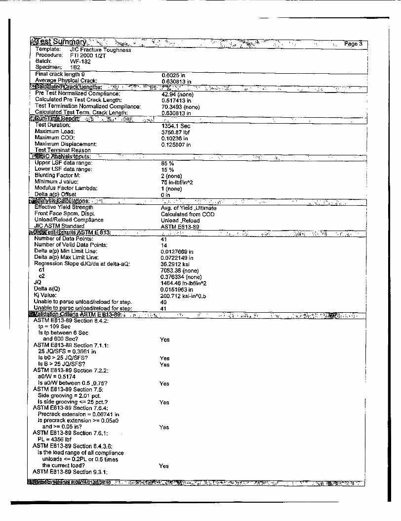
Final crack length 9 0.0025 in Average PhsialCrck 0.630813 in
Pre Test Normalized Compliance: 42.94 (none) Calculated Pre Test Crack Length: 0.517413 in Test Termination Normalized Compliance: 70.3493 (none) Calculated Test Term. Crack Length: 0.630813 in
Test Duration; 1354.1 Sec Maximum Load: 3756.87 Ibf Maximum COD: 0.10236 in Maximum Displacement: 0.125807 in Test Terminat Reason l , n•dl•7• l b, 0 Z~ ts: "7 _ - .. . . . .:,. •,.
Upper LSF data range: 85% Lower LSF data range: 15 % Blunting Factor M: 2 (none) Minimum J value: 75 in-lbffin^2 Modulus Factor Lambda: 1 (none) Delta aýp) Offset 0 in
• +•y~i .dl'• a~l• : ;;' . - .. :. " .:".... -''.. : ". .... .. '.
Effective Yield Strength Avg. of Yield iUltimate Front Face Spcm. Displ. Calculated from COD Unload/Reload Compliance Unload -Reload JIC ASTM Standard ASTM E813-89
•T M 8 3:, .: ."." ",. .,: .' , ... .;,;'• ; ', '"<. "t+ "'Num ber of Data Points: 41 '
Number of Valid Data Points: 14 Delta a(p) Min Limit Une: 0.0127669 in Delta a(p) Max Limit Uina: 0.0722149 in Regression Slope dJQ/da at delta-aQ: 36.2912 ksi
C1 7083.36 (none) c2. 0.376334 (none)
JQ 1464.46 in-lbffinA2 Delta a(Q) 0.0151963 in Kj Value: 200.712 ksi-inA0.5 Unable to parse unload/reload for step: 40 Unable to parse unload/reload for step: 41
ASTM E813-89 Section 8.4.2: tp = 109 Sec Is tp between 6 Sec
and 600 Sec? Yes ASTM E813-89 Section 7.1.1:
25 JQ/SFS = 0.3661 in Is bO > 25 JQJSFS? Yes Is B > 25 JQ/SFS?. Yes
ASTM E813-89 Section 7.2.2: a0W = 0.5174 Is a0/W between 0.5 0.75? Yes
ASTM E813-89 Section 7.5: Side grooving = 2.01 pct. Is side grooving <= 25 pct.? Yes
ASTM E813-89 Section 7.6.4: Precrack extension = 0.06741 in Is precrack extension >= 0.05a0
and >= 0.05 in? Yes ASTM E813-89 Section 7.6.1:
PL = 4356 Ibf ASTM E8 13-89 Section 8.4,3.6:
Is the load range of all compliance unloads -= 0.2PL or 0.5 times the current load? Yes
ASTM E813-89 Section 9.3.1:
•'. P ! 'tb if0• 'l0 ••: .,W--,. ' ,•' ' ,• ; r• '• !<•••' . !D:++f".' • . ...- Nk<, .- ýj ,.! ' ':':T "'11177 7•;.'- ;
pane 3

"-V ~ . . a .. , '* :. Page4 i Template: JIC Fracture Toughness Procedure: FTI 2000 112T Batch: WF-182 Specimen: 1832
Do all points used for regression lie between Delta a(p) mrin max? Yes
ASTM E813-89 Section 9.2.2: Does at least one data point lie betw
* the 0.005906 in -0.05906 in excl. Yes I ASTM E813-89 Section 9.4.1.3:
Is the slope of the regression curve I at JQ less than SFS? Yes
ASTM E813-89 Section 9.4.1.5: Are all precrack lengths within
7 pct of the average? Yes Are all final crack lengths within
7 pct. of the average? Yes ASTM E813-89 Section 9.4.1.6:
Are both near surface crack extensions within 0.02W of the extension at the center? Yes
ASTM E813-89 Section 9.4.1.7: Is the difference between the crack
extensions found from compliance and the 9-point averages within 15 pct. of either of the 9-point average or Delta a(p) max? No
EM from 9-point precrack front average = 2.586e+004 ksi
Is EM within 10 pct. of nominal E? Yes Is JQ = JIC per ASTM E813-89? No
a� �3t1O'2 ½'L�y *4: * 'V "" ". '": 4

FIGURE 3 - CRACK LENGT• 'EASUREMENT RECORD
PROMUM IDENTIFICATION Project Nurber ut-ol QA Number: a. Specimen Nuber,' 132 _ Specimen Size: '-r. Operator: -& - Date: - L4 |o Procedure: 7V " i I -I Neasuring Instr,: D-oS•'0 31- Z
NEASUREKDCF WJIDE S•~IE
2--3 .. .
7 .... a 5 -- -6-
7 8-
9 _-----A 0 B C
A - Load line S - End of Fatigue Crack/ Beginning of Crack Extension C - End of Crack Extension o - End of Nachined Notch / Beginning of Fatigue Crack
NEASURENETS Difference
A-4 A-C
I , W%.7, Measure the initial crack length ', 9 _-•SI- . (A-B) and final crack length
(A-C) for each location. CalculEdge Average .5ijq ._.t_ " ate the mean for locations I and
2 g- ,a,3A •I 9 to determine the Edge Average. 3 ,_%___ Enter these values as indicated, 4 .5 211 D _ and calculate the Specimen Mean 5 _ _____ (the mean of the Edge Average and 6 ,i1 the seven interior locations).
Specimen Mean .5VI4i . i1z
Initial Crack Length - Specimen Mean For A-B Dimension Final Crack Length - Specimen Mean For A-C Dimension
Crack Extension - (Final Crack Length - Initial Crack Length) - ,•1.3.
Measurements and calcs made: Measurements ad calcs checked:
Date: 4Date: 6{'I'I

APPENDIXD C
Fractograph


2D3
2D4

ENCLOSURE 2
PROJECT TECHNICAL PLAN FOR
REACTAOR VESSEL SURVEILLANCE PROGRAM (RVSP) CAPSULE W
ST SPECIMEN FRACTURE TOUGHNESS TESTING REVISION 2

PROJECT TECHNICAL'PLAN
FOR
WATTS BAR UNIT 1 REACTOR VESSEL SURVEILLANCE PROGRAM (RVSP) CAPSULE W
1/2 T'SPECIMEN FRACTURE TOUGHNESS TESTING
Revision 2.' June 28, 2001
Prepared.by:
N&EO BWXT Servioes, Inc.
Reviewed by: S. M. Jensen,1". N&EO BWXT Services, Inc.
Approved by: C. L. Clark, Manager N&EO. BWXT Services, Inc.
Approved b~ r D. Hindman, N&EO QA Manager N&EO BWXT Services, Inc.
Approved by:- - ,D. Briggs, Projeci Ma-*er TVA

Revisions Page
Revision Date Description
0 2/12/01 Initial release 1 3/29/01 Change proof-of-principle test specimen number from two
to four State in 2.2.5 that Westmoreland will analyze the data in accordance with ASTM El 820
2 6/28/01 Change 2.2.5 to reflect ASTM E813 was used in proof-ofprinciple tests and both ASTM E813 and E1820 will be used for irradiated specimens
1.o INTRODUCTION
1.1 Purpose
The purpose of this project is to perform machining and testing of 1/2 T compact tension specimens removed from Watts Bar Unit 1 Reactor Vessel Surveillance Program (RVSP) Capsule W.
1.2 Background
The United States Nuclear Regulatory Commission (NRC) requires a nuclear power licensee to maintain a reactor vessel surveillance program to monitor fast neutron irradiation-induced changes in the mechanical properties of reactor vessel beltline material. These changes in mechanical properties are measured by testing material specimens that have been exposed to the operating environment of a reactor vessel. Vessel material specimens are assembled into protective capsules and placed inside the vessel. The capsule is then maintained inside the reactor vessel for a specified period of operation. In this way, the material specimens within the capsule are exposed to a neutron flux similar to that experienced by the actual reactor vessel. Upon removal of the capsule, the specimens are retrieved and tested. Test results are then used to calculate pressure-temperature limits within which the reactor can be operated safely or to verify the current limits remain conservative through the next service interval.
1.3 Workscope
The workscope of this project includes machining and testing of 1/2T compact tension specimens based on an acceptable specimen design, which will be approved by TVA, and the reporting of test results.
2.0 DESCRIPTION OF ACTIVITIES
2.1 Specimen Retrieval
Capsule W was received at the BWXT Services, Inc. (BWXS) Lynchburg Technology Center (LTC) in January 2001 and was subsequently disassembled in its Hot Cell Facility. Following the disassembly, specimens were inventoried and stored. There are twelve (12) 1/2 T compact tension specimens and one bend bar in this capsule. Four axial orientation 1/2T compact tension specimens will be machined and tested.
2.2 Machining and Testing of Unirradiated Specimens
Some machining on the 1/2T compact tension specimens is expected since the original specimens were manufactured in accordance with ASTM E399 not ASTM E1820, which is the Standard that will be used for testing. A draft engineering drawing has been sent to TVA for review (see Attachment A) and will be used as the specimen design basis- Proof-of-principle tests will be performed prior to actual testing.
To simulate the fact that the material of interest has alow upper shelf energy, an A508 Class 2 forging material with a low upper shelf energy is an ideal candidate; however, BWXS has gone
1BWXS, LTC TVA Fracture Toughness Testing Test Plan

EWXS, LTC TVA Fracture Toughness Testing Test Plan 2
through its inventory and identified a reactor vessel steel weld metal with a low upper shelf energy of 70 ft-lb, which is more representative of the Watts Bar material. A total of four (4) unifradiated specimens will be machined and tested at 390 OF. Two of those four specimens will be machined in accordance with ASTM El 820 and two will be machined in accordance with the BWXS design. Proof-of-principle tests will be conducted in accordance with ASTM E1820 to determine the adequacy of the BWXS design and will be witnessed by NRC representatives.
The compact tension specimen testing will be conducted in accordance with Technical Procedure TP-1 77 "Automated, Single Specimen I-integral Fracture Toughness Testing" (latest revision, see Attachment B). TP-177 is in compliance with ASTM E1820. The certified software fTEST will be used to control the test machine and acquire the data automatically during the test. The actual test temperature determined by TVA Project Manager is 390 OF. Test temperature is controlled to within ± 51F.
2.2.1 Specimen Machining
Unirradiated specimens will be machined using a combination of an EDM machine and a milling machine while only an EDM machine will be used for the irradiated specimens. Specimen dimension will be verified and documented prior to testing.
2.2.2 Precracking
Fracture toughness specimens need precracking to grow the cracks to appropriate lengths. In this case, precracking will be conducted per TP-177.
2.2.3 Temperature Control
Elevated temperature testing will be performed in an ATS split type furnace, which is designed to handle both elevated temperature and sub-zero temperature testing. Test temperature is controlled to within * 5°F.

2.2.4 Fracture Toughness Testing Equipment
Equipment may be replaced by an equivalent or better equipment.
Instrument QA Status Range Accuracy
MTS TestStar System N/A N/A N/A (Digitally Controlled)
MTS 55 or 3 kips Load Cells Certified 0.1-0.5 (FS) + 1% 0.5-1.0 (FS) +0.05%
Clip Gage Calibrate prior to 0.1. -L 1.0% use 0.15" +1.0%
0.3" + 1.0% 0.5" + 1.0%
MTS LVDT Certified 0-6" +0.001"
Dial Caliper Certified 0-6" :E0.001"
ELPH5 Digital Temperature Certified -330OF - 2500OF + 2.00F Readout
Type K Thermocouples N/A - + 4.00F
Colorado Video Micrometer Calibrated prior to 0-2. 1 0.001" use
Micro Head Certified 0-1" + 0.001'
Digital Voltmeter Certified -20V to +20V :L 1.0%
2.2.5 Data Analysis
Proof-of-principle test data were analyzed using ASTM E813 to validate BWXS specimen design. Irradiated specimen test data will be analyzed in accordance with ASTM El 820 by Westmoreland Mechanical Testing & Research Inc. and with ASTM E813 by BWXS. All test results will be reported.
2.2.6 Reportable Test Results
For each fracture toughness test specimen, the following results shall be reported:
a. Load versus displacement curve b. J-R curve c. Test temperature d. Loading rate e. Jic (if criteria not violated) or J. f. Initial crack length g. Final crack length h. Photograph of fracture surface
TVA Fracture Toughness Testing Test PlanBWXS,
LTC3BWXS, LTC

TVA Fracture Toughness Testing Test Plan
2.2.7 Approval of Report
A report documenting the test results and findings will be submitted to TVA for review and approval. The actual specimen will not be tested until the approval is obtained from TVA
2.3 Machining and Testing of Irradiated Specimens
The same procedures used in machining and testing of unirradiated specimens will be used for the actual specimens. A Radiation Work Permit, which provides radiological control of the work, will be obtained prior to work. Appropriate shielding will be built around the equipment to reduce operator exposure. Specimen dimensions will be verified to the extent practical due to the concern of operator exposure. If such measurements are not practical, the information will be obtained from the manufacture report. This testing will also be witnessed by NRC representatives.
2.4 Evaluation of the Equivalent Margin Analysis
As part of the overall scope of work to test and evaluate Reactor Vessel Surveillance Program Capsule W from Watts Bar Nuclear Unit 1, J-R data derived from compact fracture specimens of Capsule W will be evaluated as follows:
1) a review of the equivalent margin analysis performed by Westinghouse 2) a comparison of the J-R data from capsule W and the projected J-R curves used in the
equivalent margin analysis and 3) an evaluation regarding the continued validity of the equivalent margin analysis based
on the Capsule W J-R data.
3.0 STORAGE OF TEST SPECIMENS
Unless specified by TVA, all tested irradiated compact tension specimens will be catalogued, then placed in a suitably labeled paint can and stored in the LTC Long-Term RVSP Storage Room.
Unless specified by TVA, for untested irradiated specimens, specimens will be catalogued, then placed in a suitably labeled paint can (separated from the tested ones) and be stored in the LTC Long-Term RVSP Storage Room.
4.0 DISPOSAL OF SPECIMENS
TVA may require that both tested and untested specimens be disposed of at the end of the project. Specimens will be disposed with other wastes and the disposal site is Barnweil, SC.
BWXS, LTC 4

BWXS, LTC TVA Fracture Toughness Testing Test Plan 5
5.0 QUALITY ASSURANCE
This project is designated as safety related and will be performed in accordance with a project specific QA plan (BWXS N&EO QA Plan 00001, dated Nov. 8, 2000), which has been approved by TVA.
6.0 REPORTING
All test data, observations, and conclusions will be reported to TVA in a BWVXS formal report. Preliminary data may be transmitted to TVA as it becomes available during the course of the project. These results, however, will not be delivered until the satisfactory completion of a BWXS Quality Assurance project review of all project records.

ENCLOSURE 3
TECHNICAL PROCEDURE (TP)-177 AUTOMATED, SINGLE-SPECIMEN J-INTEGRAL FRACTURE TOUGHNESS TESTING
REVISION 9
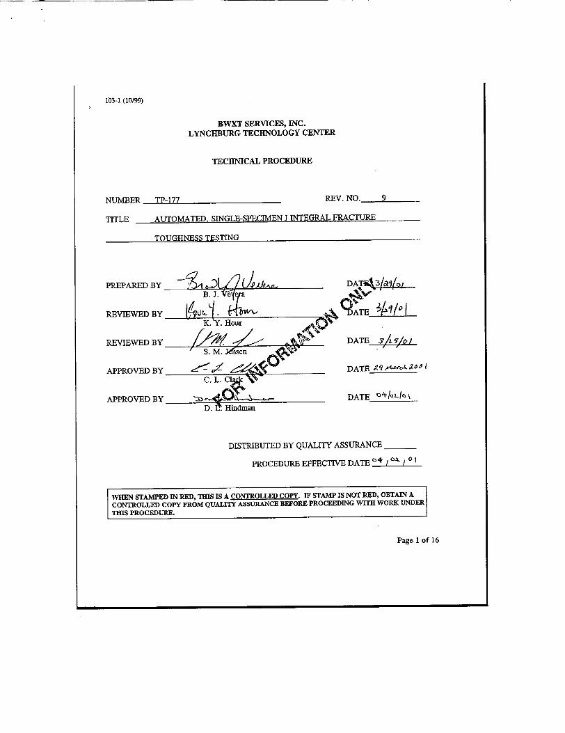
103-1 (10/99)
BWXT SERVICES, INC. LYNCHBURG TECHNOLOGY CENTER
TECHNICAL PROCEDURE
NUMBER TP-177 REV. NO. 9
TITLE AUTOMATED, SINGLE-SPECIMEN I-INTEGRAL FRACTURE
TnT TanMrcc Tri�TTMfl
PREPARED BY
REVIEWED BY
REVIEWED BY
APPROVED BY
APPROVED BY
C. L.C
DATaký3/'a15
9 ATE 3!q/o
DATE -7A ,/,i 1
DATE qSLOOI
DATE_____D. 2HindmanJ
DISTRIBUTED BY QUALITY ASSURANCE
PROCEDURE EFFECTIVE DATE / o I
Page 1 of 16
WHEN STAMPED IN RED, THIS IS A CONTROLLED COPY. IF STAMP IS NOT RED, OBTAIN A CONTROLLED COPY FROM QUALITY ASSURANCE BEFORE PROCEEDING WITH WORK UNDER THIS PROCEDURE.
-rnTTr--UMrVZ T'PIZTING

LYNCHBURG TECHNOLOGY CENTER TECHNICAL PROCEDURE
0 4/09182
1 06/08/84
2 12/13/91
3 03/20/93
4 07/07/94
5 09/07/94
6 03/31/97
7 02/29/00
8 02/14/01
9 3/29/01
ORIGINAL RELEASE
COMPLETE REVISION
COMPLETE REVISION
DISTRIBUTION CHANGE ONLY
MAJOR REVISION IN SECTION 7.0 AND 8.0 TO ADDRESS THE REPLACEMENT OF OLD 442 SYSTEM WITH MORE ADVANCED TESTSTAR SYSTEM AND THE INSTALLATION OF NEW SOFTWARE MTS 790.50 FOR MACHINE CONTROL AND DATA ACQUISITION. PRE-CRACKING WAS ALSO INCLUDED IN THIS TP. MINOR REVISIONS IN OTHER SECTIONS.
MINOR REVISIONS WERE MADE IN SECTIONS 1.1, 7.4.2, AND 7.4.5.
MAJOR REVISION TO CONFORM WITH NEW STANDARD PRACTICE MANUAL DEFINITIONS AND CHANGES TO THE PROCEDURE
CHANGE COMPANY NAME, CHANGE REFERENCES AND REVISED ACCORDING TO NEO-QIP-1 3.
ATTACHMENT FOR CRACK LENGTH MEASUREMENT ADDED. REFERENCES TO ASTM STANDARD E1820 ADDED.
REVISED 12.0 AND 12.5 TO INCLUDE ASTM STANDARDS E1737 AND El 820.
103-2 (7/1/98)
PROCEDURE NO. TP-177 PAGE NO. 2
103-3 (7/1/98) LYNCHBURG TECHNOLOGY CENTER TECHNICAL PROCEDURE
PROCEDURE NO. TP-177 PAGE NO. 3
REV. NO. 9 DATE: 03/29/01
1.0 APPLICABILITY
This procedure is to be used by authorized individuals in Nuclear Materials Engineering (NME) trained in the proper performance of the techniques involved.
2.0 PURPOSE
2.1 This technical procedure defines the operator qualifications, equipment requirements, and use
of the JTEST.R01 software, which conducts an unloading compliance single specimen I-Test
in compliance with ASTM Standards E813, El152, E 1737, E 1820, and E 1921.
2.2 This procedure assumes the use of compact tension specimens and bend specimens (SE(B)).
3.0 REFERENCES
3.1 ASTM Standard E 813, "Standard Test Method for J1,, A Measure of Fracture Toughness."
3.2 ASTM Standard E 1152, "Standard Test Method for Determining J-R Curves."
3.3 ASTM Standard E 1737, "Standard Test Method for J-Integral Characterization of Fracture Toughness."
3.4 ASTM Standard E 1820, "Standard Test Method for Measurement of Fracture Toughness."
3.5 ASTM Standard, "E 1921 Test Method for Determination of Reference Temperature, T0, for Ferritic Steels in the Transition Range."
3.6 TP-585, "Calibration Procedure for NITS Clip Gage/Range Card Combination.'
3.7 TP-583, "Calibration Procedure for Video Micrometer System."
3.8 MTS 790.50 "Fracture Toughness Test Application Software" manual.
3.9 TP-640, "Calibration Procedure for MTS 490.21 DC Conditioners."
4.0 TRAINING REQUIREMENTS
4.1 All persons working under this procedure shall be trained in its requirements and designated in the Fatigue & Fracture Laboratory operator qualifications list as qualified to perform this procedure. The Project Engineer may qualify himself/herself as an operator.

LYNCHBURG TECHNOLOGY CENTER TECHNICAL PROCEDURE
PAGE NO. 4
DATE: 03/29/01
4.2 The personnel conducting the single specimen J-Test shall have demonstrated their competency in the use of JTEST.R01 software (MTS 790.50 software), automated MTS TestStar test equipment, and supporting laboratory equipment including temperature measurement and dimensional measuring devices to the satisfaction of the Project Engineer.
4-3 The Project Engineer should be familiar with the requirements of ASTM Standards E 813, E 1152, E 1737, E 1820 and E 1921, this technical procedure, and manual of MTS 790.50 software. The operator should be trained in the use of this technical procedure and MTS 790.50 software manual. Training shall be documented on Form 619, Nuclear & Environmental Operations Personnel Training/Qualification Report.
4.4 The individual should be able to conduct one J-integral test without assistance to the satisfaction of the Project Engineer.
5.0 EQUIPMENT AND SUPPLIES
5.1 The following equipment shall be used in performing the 1-Test.
5.2 The following equipment constitutes the MTS TestStar servo-hydraulic test system.
Item
MTS 312 Series Load Frame, Series 204 Hydraulic Actuator, Series 252 Servovalve, Series 294 Hydraulic Service Manifold, Series 506 Hydraulic Power Supply 490 Controller, 490.14 Value Driver 490.30 Work Station Communication Interface 490.05 Load Unit Control Panel
Minimum Specifications
The system must be of sufficient capacity to maintain crack extension of the specimen. Typically, it must be able to exceed the specimen's anticipated limit load.
Recommended Eouipment
MTS only
103-3 (7/1198)
PROCEDURE NO. TP-177
REV. NO. 9
I I

LYNCHBURG TECHNOLOGY CENTER TECHNICAL PROCEDURE
PROCEDURE NO. TP-177
REV. NO. 9
PAGE NO. 5
DATE: 03/29101
5-3 The following equipment constitutes the MTS TestStar servo-hydraulic test system.
Item
LVDT within Actuator
MTS Load Cell
Clip gage-style Extensometer
MTS 490.22 AC Conditioner
MTS 490.21 DC Conditioner
MTS 490.21 DC Conditioner
Minimum Specifications
Must have travel compatible with Actuator working range
Working range greater than specimen's anticipated limit load
Sufficient range to test intended specimens; cartridge card specific to gage
Connected to the 490 Controller; calibrated as part of the LVDT
Connected to the 490 Controller and the load cell
Connected to the 490 Controller and the clip gage extensometer
Recommended Equipment
MTS-supplied or equivalent
MTS 661.23A or
equivalent
MTS 632.02 or .03 series, or B&W-made gage, or equivalent
MTS 490.22 only
MTS 490.21 only
MTS 490.21 only
5.4 The following equipment is also necessary for the J-Test.
Minimum Specifications
Support extensometer and micrometer head
Certified Micrometer Head
Recommended Equipment
MTS Calibration fixture or equivalent
MTS 650.03 or equivalent
103-3 (7/1/98)
Item
Calibration Fixture
0.0001-inch resolution

LYNCIIBURG TECHNOLOGY CENTER TECHNICAL PROCEDURE
PROCEDURE NO. TP-177
REV. NO. 9
PAGE NO. 6
DATE: 03/29/01
5.5 The following equipment is also necessary for the J-Test.
Item
Digital Voltmeter
Caliper
IBM Personal Computer
Monitor and Hard copy unit
Thermocouple 0.75% of reading
Digital Temperature Readout
Video Monitor
Video Camera
Video Micrometer
High Intensity Lights
Platform Stage
Minimum Specifications
Resolution 0.001V in 10V range; Accuracy > 0.01% of range
0.0005 inch resolution
> 12 Megabyte RAM
Must have graphics capability
Type K, +/-2.2"C or
Accurate to +/- 4°F
Monitor capable of capable of functioning with system
Video camera with zoom lens and focus control
Range 0" to maximum expected crack length Resolution: .001"
Light sufficient to adequately illuminate darkened test specimens
For holding specimens
Recommended Equioment
Keitheley 2001 or equivalent
Mitutoyo 6" caliper or equivalent
IBM 486 series or better
From Approved Supplier
Thermoelectric ELPH5 or equivalent
Sony Color CVM-1271 or equivalent
Panasonic WV-CP612 or equivalent
Colorado Video Inc. Model 305 or equivalent
Microcontrol stage or equivalent
f03-3 (7/1/98)
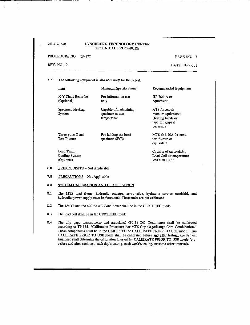
LYNCREBURG TECHNOLOGY CENTER TECHNICAL PROCEDURE
PROCEDURE NO. TP-177 PAGE NO. 7
DATE: 03/29/01
5.6 The following equipment is also necessary for the J-Test.
item
X-Y Chart Recorder (Optional)
Specimen Heating System
Three-point Bend Test Fixture
Minimum Specifications
For information use only
Capable of maintaining specimen at test temperature
For holding the bend specimen SE(B)
Load Train Cooling System (Optional)
Recommended Eouipment
HP 7044A or equivalent
ATS forced-air oven or equivalent; Heating bands or tape for grips if necessary
MTS 642. 1OA-01 bend test fixture or equivalent
Capable of maintaining Load Cell at temperature less than 1000F
6.0 PREREQUISITE - Not Applicable
7.0 PRECAUTIONS - Not Applicable
8.0 SYSTEM CALIBRATION AND CERTIFICATION
8.1 The MTS load frame, hydraulic actuator, servo-valve, hydraulic service manifold, and hydraulic power supply must be fbnctional. These units are not calibrated.
8.2 The LVDT and the 490.22 AC Conditioner shall be in the CERTIFIED mode.
8.3 The load cell shall be in the CERTIFIED mode.
8.4 The clip gage extensometer and associated 490.21 DC Conditioner shall be calibrated according to TP-585, "Calibration Procedure For MTS Clip Gage/Range Card Combination." These components shall be in the CERTIFIED or CALIBRATE PRIOR TO USE mode. The CALIBRATE PRIOR TO USE mode shall be calibrated before and after testing; the Project Engineer shall determine the calibration interval for CALIBRATE PRIOR TO USE mode (e.g. before and after each test, each day's testing, each week's testing, or some other interval).
f03-3 (7/1/98)
REV. NO. 9
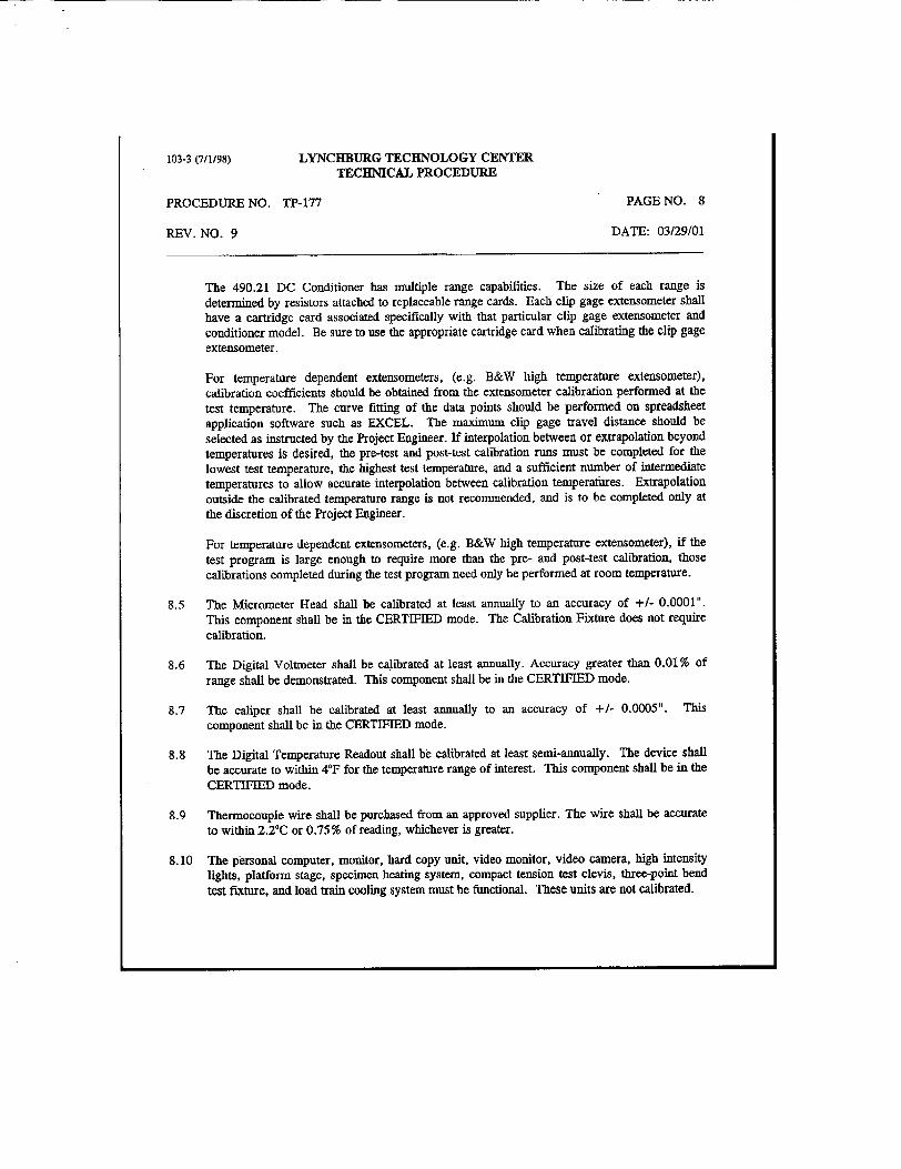
103-3 (7/1/98) LYNCHBURG TECHNOLOGY CENTER TECHNICAL PROCEDURE
PROCEDURE NO. TP-177 PAGE NO. 8
REV. NO. 9 DATE: 03/29/01
The 490.21 DC Conditioner has multiple range capabilities. The size of each range is determined by resistors attached to replaceable range cards. Each clip gage extensometer shall have a cartridge card associated specifically with that particular clip gage extensometer and conditioner model. Be sure to use the appropriate cartridge card when calibrating the clip gage extensometer.
For temperature dependent extensometers, (e.g. B&W high temperature extensometer), calibration coefficients should be obtained from the extensometer calibration performed at the test temperature. The curve fitting of the data points should be performed on spreadsheet application software such as EXCEL. The maximum clip gage travel distance should be selected as instructed by the Project Engineer. If interpolation between or extrapolation beyond temperatures is desired, the pre-test and post-test calibration runs must be completed for the lowest test temperature, the highest test temperature, and a sufficient number of intermediate temperatures to allow accurate interpolation between calibration temperatbres. Extrapolation outside the calibrated temperature range is not recommended, and is to be completed only at the discretion of the Project Engineer.
For temperature dependent extensometers, (e.g. B&W high temperature extensometer), if the test program is large enough to require more than the pre- and post-test calibration, those calibrations completed during the test program need only be performed at room temperature.
8.5 The Micrometer Head shall be calibrated at least annually to an accuracy of +/- 0.0001". This component shall be in the CERTIFIED mode. The Calibration Fixture does not require calibration.
8.6 The Digital Voltmeter shall be calibrated at least annually. Accuracy greater than 0.01% of range shall be demonstrated. This component shall be in the CERTIFIED mode.
8.7 The caliper shall be calibrated at least annually to an accuracy of +/- 0.0005". This component shall be in the CERTIFIED mode.
8.8 The Digital Temperature Readout shall bb calibrated at least semi-annually. The device shall be accurate to within 40F for the temperature range of interest. This component shall be in the CERTIFIED mode.
8.9 Thermocouple wire shall be purchased from an approved supplier. The wire shall be accurate to within 2.20 C or 0.75 % of reading, whichever is greater.
8.10 The personal computer, monitor, hard copy unit, video monitor, video camera, high intensity lights, platform stage, specimen heating system, compact tension test clevis, three-point bend test fixture, and load train cooling system must be functional. These units are not calibrated.

103-3 (7/1/98) LYNCHBURG TECHNOLOGY CENTER TECNIMCAL PROCEDURE
PROCEDURE NO. TP-177 PAGE NO. 9
REV. NO. 9 DATE: 03/29/01
8.11 The Video Micrometer system shall be calibrated according to TP-583, "Calibration Procedure For Video Micrometer System." The calibration shall be done before and after testing; the project leader shall determine the calibration interval (e.g. before and after each test, each day's testing, each week's testing, or some other interval). This component shall be in the CALIBRATE PRIOR TO USE mode.
8.12 An x-y recorder may be used to record load and displacement signals during the test at the discretion of the project leader. Such a recorder is for information use only according to this procedure and need not be calibrated.
9.0 TEST LOG
9.1 A test log, (e.g., project logbook, project file and computer files), shall be maintained for each specimen tested. The following information shall be recorded in the log:
a. Project number, test specimen ID, project lead engineer, date of test, equipment operator, and the technical procedure used.
b. Necessary specimen information by type, (e.g., compact tension or bend specimen), shall be maintained. Nominal specimen dimensions or measurements should be used.
c. Load cell serial number, serial number for the load cell 490.21 conditioner, cartridge card number, and any form generated by TP-640 (Ref. 3.9).
d. Clip gage extensometer serial number, serial number for the clip gage 490.21 conditioner, cartridge card number, and any form generated by TP-640 (Ref. 3.9).
f. During the test of the specimen, clip gage, and load cell temperatures shall be monitored and entered into the test log. The identification of the thermocouple and digital temperature readout used for these measurements shall be entered into the test log.
9.2 All entries in the log shall be made in ink. The test log must be signed and dated upon completion. In addition, any changes or corrections to the log must be signed and dated.
9.3 Upon completion of all J-Integral testing in the project, the test results will be included in the
project file as directed in Section 11.0 or 12.0.
10.0 SYSTEM SETUP
10,1 Log on MTS TestStar II using the appropriate configuration file.

103-3 (7/1198) LYNCHBURG TECHNOLOGY CENTER TECHNICAL PROCEDURE
PROCEDURE NO. TP-177 PAGE NO. 10
REV. NO. 9 DATE: 03/29101
10.2 The following steps should be performed at least once each day as part of the system set-up prompted by the computer program.
10.2.1 Select the load conditioner range needed for the testing. Monitor the load conditioner output from the screen. Auto zero the output voltage to 0 V.
Check the shunt calibration voltage. Record shunt voltage in the test log. Compare this value with the previous calibration and the difference should be no more than ±1%.
10.2.2 Select the clip gage extensometer range needed for testing. Auto zero the output voltage to 0 V. Check the shunt calibration voltage. Record shunt voltage in the test logbook.
Compare this value with the previous calibration and the difference should be within by more than ±1%.
10.3 If load cell or extensometer are changed during the day, repeat 10.2.1 or 10.2.2 as required.
10.4 Load the computer with JTEST.R01 (MTS 790.50 "Fracture Toughness Testing Application Software") and choose the J,, template and an appropriate procedure in the DEFINE mode in the Main manual window.
10.4.1 Edit Precracking Parameters (if applicable)
Define the following parameters used for precracking.
a. Final K,. b. Load Ratio, R c. Test Frequency d. Final Crack Length (iuch) e. Upper LSF data range f. Lower LSF data range
10.4.2 Edit Execution Parameters
Define the following parameters used for J1c testing. (Consult the Project Engineer unless otherwise stated.)
a. Precycle Load (Ibf)
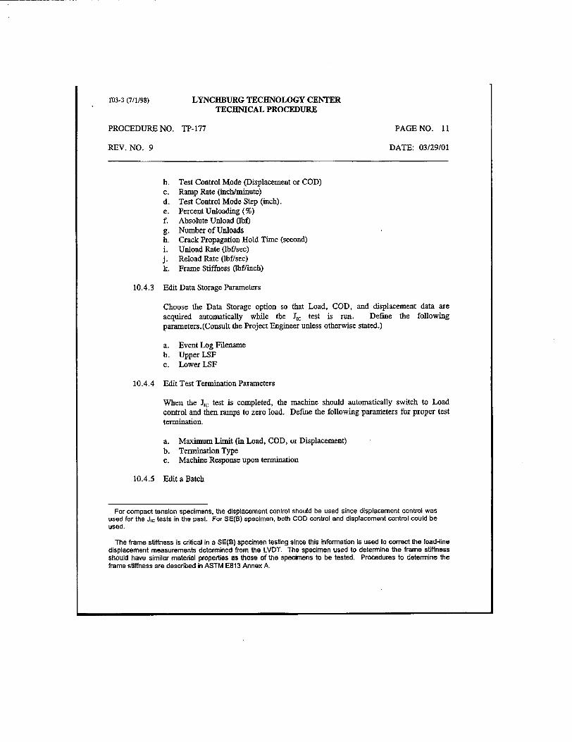
103-3 (7/1/98) LYNCHBURG TECHNOLOGY CENTER TECHNICAL PROCEDURE
PROCEDURE NO. TP-177 PAGE NO. 11
REV. NO. 9 DATE: 03/29/01
b. Test Control Mode (Displacement or COD) c. Ramp Rate (inch/minute) d. Test Control Mode Step (inch). e. Percent Unloading (%) f. Absolute Unload (bf) g. Number of Unloads h. Crack Propagation Hold Time (second) i. Unload Rate (lbf/sec) j. Reload Rate (lbf/sec) k. Frame Stiffness (lbflinch)
10.4.3 Edit Data Storage Parameters
Choose the Data Storage option so that Load, COD, and displacement data are acquired automatically while the J, test is run. Define the following parameters. (Consult the Project Engineer unless otherwise stated.)
a. Event Log Filename b. Upper LSF c. Lower LSF
10.4.4 Edit Test Termination Parameters
When the ],, test is completed, the machine should automatically switch to Load control and then ramps to zero load. Define the following parameters for proper test termination.
a. Maximum Limit (in Load, COD, or Displacement) b. Termination Type c. Machine Response upon termination
10.4.5 Edit a Batch
For compact tension specimens, the displacement control should be used since displacement control was used for the J1c tests in the past For SE(B) specimen, both COD control and displacement control could be used.
The frame stiffness is critical in a SE(B) specimen testing since this information Is used to correct the load-line displacement measurements determined from the LVDT. The specimen used to determine the frame stiffness should have similar material properties as those of the specimens to be tested. Procedures to determine the frame stiffness are described in ASTM E813 Annex A-

103-3 (7/1/98) LYNCHBURG TECHNOLOGY CENTER TECHNICAL PROCEDURE
PROCEDURE NO. TP-177 PAGE NO. 12
REV. NO. 9 DATE: 03/29101
790.50 offers an option for specimens of the same geometries be treated as a batch, thus saving the time to redefine parameters related to the specimen dimensions, material properties, and clip gage. The Project Engineer should decide how the specimens should be organized to take advantage of this option.
a. Comments (if any) b. Specimen Geometry (choose from LLC(T), SE(B), FFC(T), DC(T)) c. Specimen Identification (Unique within a batch) d. Width (inch) e. Notch Length (inch) f. Thickness (inch) g. Net Thickness (inch) h. Modulus of Elasticity (ksi)
Modulus values should be adjusted for temperature using the equation: (Note: for low alloy steels only)
Modulus (ksi) = 29480 - (5.055 x (0F))
(Consult the project engineer for materials other than low alloy steels.)
i. Yield Strength (ksi) j. Ultimate Tensile Strength (ksi) k. Poisson's Ratio 1. Crack Orientation m. Pin Center from Crack Plane (inch) n. C.O.D. Half-Gage Length (inch) o. C.O.D. Distance from Load Line (inch) p. Test Temperature (0F)
10.5 The MTS hydraulics and electronics shall be warmed up prior to testing. The electronics will be considered warmed up if they have been powered up for one-half hour before use.
10.6 All fixtures, heating and cooling equipment to be used during the testing should be mounted.
11.0 TEST PROCEDURE
11.1 In the Main menu window, choose the EXECUTE mode and select the appropriate template, procedure, batch, and specimen.
11.2 Make sure that the appropriate safety interlocks are set up. Mount the specimen in the MTS machine.

1D3-3 (7/1/98) LYNCHBURG TECHNOLOGY CENTER TECHNICAL PROCEDURE
PROCEDURE NO. TP-177 PAGE NO. 13
REV. NO. 9 DATE: 03/29101
11.3 If precracking the specimen is desirable, choose PreCrack from the Parameters and check the
parameters of "Precrack" before running the test. Follow the steps for precracking.
11.3.1 Choose load, COD (clip gage), and displacement as sensors to acquire data.
11.3.2 In Assign Modulus menu, choose Compliance Measurement to load the specimen and verify that the crack length and modulus are consistent with the user defined values.
11.3.3 Select appropriate display options.
11.3.4 Press Run to start precracking. This precracking process is automatically controlled (in force) by the 790.50 software until the final crack length specified by the user is met.
11.3.5 Assign the results of precracking such as number of cycles, final crack length, final and precrack P., and final and precrack K. will be recorded for use in the J1c testing.
11.3.6 Put the specimen under slight tension force (or compression force for bend specimen) while heating or cooling the specimen.
11.4 Affix a length of thermocouple wire on the specimen adjacent to the crack tip. Make sure that the thermocouple wire will not interfere with the deflection of the specimen.
11.5 Heat/cool the specimen to the desired test temperature. The specimen shall be maintained at the test temperature (+/- 50F) for a minimum of 20 minutes or 30 min/inch of specimen thickness whichever greater before testing begins. Record the specimen, clip gage extensometer, and load cell temperatures on the test log at the
start of soaking, start of test, and end of test.
11.6 Press OK to enter Jc testing manual.
11.6.1 Choose load, COD (clip gage), and displacement as sensors to acquire data.
In the case of testing large activated specimens, a correlation between the reading of the temperature controlled channel of the furnace and the reading from an unirradiated specimen may be established so that no local thermocouple wire is required to minimize personinel exposure. This calibration shall be repeatable and properly documented.

1b3-3 (7/1/98) LYNCHBURG TECHNOLOGY CENTER TECHNICAL PROCEDURE
PROCEDURE NO. TP-177 PAGE NO. 14
REV. NO. 9 DATE: 03129101
11.6.2 In Check Crack Length menu, choose Compliance Measurement to load the specimen and verify that the crack length is consistent with the final crack length from precracking process.
Repeat the measurements at least three times. No individual value shall differ from
the mean by more than ±.002W. (For E 813, E 1152, E 1820, and E 1737 test only). If the results are satisfactory, proceed to the next step.
11.6.3 Select appropriate display options.
11.6.4 Press Run to start J, testing.
11.7 Throughout the test, monitor the load cell temperature and maintain below 100lF.
11.8 After completion of the test, the specimen should be removed from the MTS. The crack front of one fracture face will be examined and measured. To improve resolution during examination, the test specimen can be heat tinted (usually at 500 to 600'F for 10 - 30 min) to mark the position of the final crack front. The specimen could either be cooled, perhaps to liquid nitrogen temperatures, and then mounted back into the MTS and pulled apart manually or be fatigue-cycled to failure to minimize further specimen deformation. The loads for the fatigue cycling should be chosen carefully to avoid significant deformation. Care should be taken not to drop the broken halves or mar the fracture surfaces in any way. Any specimens which are accidentally mishandled should be labeled as such.
11.9 The initial and final crack fronts shall be measured on one of the fracture surfaces at nine equally spaced points centered about the specimen centerline and extending to within .005W of the root of the sidegrooves. The readings shall be taken sequentially beginning at one side of the specimen, and shall be entered in order in the test log so that the nine readings provide an accurate portrayal of the crack front profile through the thickness of the specimen. Form TP177, or some equivalent record, should be used to document the fracture surface measurements.
12.0 DATA ANALYSIS FOR A J-TEST per ASTM E813, El 152, E1820, E1737
J-TEST.R01 software has the ability to perform an E813 and/or El 152 post-test data analysis.
The project engineer shall develop or identify a computer code that has the ability to perform an E1737 or E1820 post data analysis.
12.1 In the 790.50 Main menu, choose ANALYZE and select the appropriate template, procedure, and batch.

[M3-3 (7/1/98) LYNCHBURG TECHNOLOGY CENTER TECHNICAL PROCEDURE
PROCEDURE NO. TP-177 PAGE NO. 15
REV. NO. 9 DATE: 03/29/01
12.2 In the Input menu, select desirable Calculations and Methods for analyzing the data. Consult Project Engineer for the selections.
12.3 Select summaries of the test results. All items displayed in the Summary Categories should be chosen.
12.4 Enter precrack length 1-9 and final crack length 1-9 measured after the test using video micrometer.
12.5 Check to see if there are any E813, E1737, or E1820 violations (consistent with the Test Plan or Customer Purchase Order).
12.6 Generate the desirable tables and plots.
13.0 DATA ANALYSIS FOR TRANSITION RANGE TEST per ASTM 1921
Since JTEST.R01 is used to perform a post-test analysis on a J-test with crack extension, this
software is not suitable to analyze a transition range fracture toughness test where no or limited crack extension is expected. In such case, MLINK (latest revision) is used to analyze a transition range fracture toughness test.
13.1 Load the JLINK in a BASIC programming environment.
13.2 Run JLINK.
13.3 Input test parameters as required by the software.
13.4 The J. value is calculated by SLINK. KM is calculated as follows:
K j, = a cE)V
14.0 TEST RECORD FOR A J-TEST
14.1 All test results shall be included in the project log.
14.2 The record for each specimen tested shall include:
a. Summary of test. (Results generated by JTEST.R01)
b. Summary of all crack length measurements.

LYNCHBURG TECHNOLOGY CENTER TECHNICAL PROCEDURE
PROCEDURE NO. TP-177
REV. NO. 9
PAGE NO. 16
DATE: 03/29/01
C. J-R curve for a E 813, E 1152, E 1820, and E 1737 test as required.
d. The output from any analysis requested by the Project Engineer.
e. (Optional) Photograph of fracture surface.
15.0 TEST RECORD FOR A TRANSITION RANGE TEST
15.1 All test results shall be included in the project log.
15.2 The record for each specimen tested shall include:
a. Outputs generated by software JLINK.
b. Summary of all crack length measurements.
c. The output from any analysis requested by the Project Engineer.
d. (Optional) Photograph of fracture surface.
16.0 DEFINITIONS - Not Applicable
17.0 ATTACHMENTS/FORMS
TP-177, "Crack Length Measurement Record"
103-3 (7/1198)


![arXiv:cond-mat/0107563v1 [cond-mat.soft] 27 Jul 2001 · 2018. 11. 13. · arXiv:cond-mat/0107563v1 [cond-mat.soft] 27 Jul 2001 Under consideration for publication in J. Fluid Mech](https://img.pdfslide.us/doc/110x75/604ffbc193be7020fa695e82/arxivcond-mat0107563v1-cond-matsoft-27-jul-2001-2018-11-13-arxivcond-mat0107563v1.jpg)


![arXiv:cond-mat/0107399v1 [cond-mat.str-el] 19 Jul 2001](https://img.pdfslide.us/doc/110x75/61d895533ad74b14512e9b1b/arxivcond-mat0107399v1-cond-matstr-el-19-jul-2001.jpg)

![arXiv:math/0007053v3 [math.DG] 17 Jul 2001](https://img.pdfslide.us/doc/110x75/628779cfe22c357ef76c5d56/arxivmath0007053v3-mathdg-17-jul-2001.jpg)