Embed Size (px)
Citation preview
Design Plan JTLS-2012-11384 ROLANDS & ASSOCIATES Corporation
JTLS 4.1.0.0 519 25 February 2013
JTLS-2012-11384 Direct Link To MUSE
Bill Lynn, Donna Womble, Ellen Roland
1.0 Summary of Model Change Request
This Engineering Change Proposal (ECP) enables the Multi-User Simulation Environment (MUSE)to generate an Unmanned Aerial Vehicle (UAV) display of the JTLS theater for exercises andtraining. The JTLS design team expects that this UAV view will include displays of completeGround Unit, Ship, Convoy, and Air Mission entities. This link will also support the firing ofweapons from within MUSE, munition detonations, and the interaction between JTLS-ownedobjects, such as Air Defense sites, and the MUSE-owned UAVs.
2.0 Design Summary
JTLS has an extended history of attempts to formalize a link to a UAV simulator. The inability toproduce a simulated UAV video feed for today’s military environment, in which the use of dronesor UAVs is increasingly important, has proven detrimental to the continued use of JTLS to supportreal-world training events. Previous attempts to formalize this capability are summarized inTable 1.
Table 1. Previously Attempted Links To MUSE
ATTEMPT DESCRIPTION WHAT WENT WRONG
Distributed Interactive Simulation (DIS) Link This project never proceeded beyond initial testing. A typical JTLS database has more than 3.5 million entities and DIS required a heartbeat every 3 to 5 seconds. A JTLS heartbeat would saturate the network and all models would come to a standstill.
Direct Link Using Aggregate JTLS Object Distribution Authority (JODA). This link was very successful and JTLS showed naval damage in greater detail than any other model that also linked to MUSE.
MUSE accepted the aggregate information, which included a unit center of mass location and the numbers and types of Combat systems. MUSE then created a template and placed the unit’s Combat Systems in a reasonable location around the aggregate unit’s center of mass. The issue with this implementation was that other entity level models also used the JTLS aggregate information and their customary template structure logic to determine where the entities were located. The result was an inconsistency between what the UAV showed and what an external intelligence model showed.
ROLANDS & ASSOCIATES Corporation Design Plan JTLS-2012-11384
25 February 2013 520 JTLS 4.1.0.0
3.0 Detailed Design
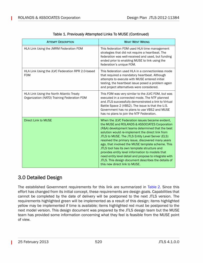
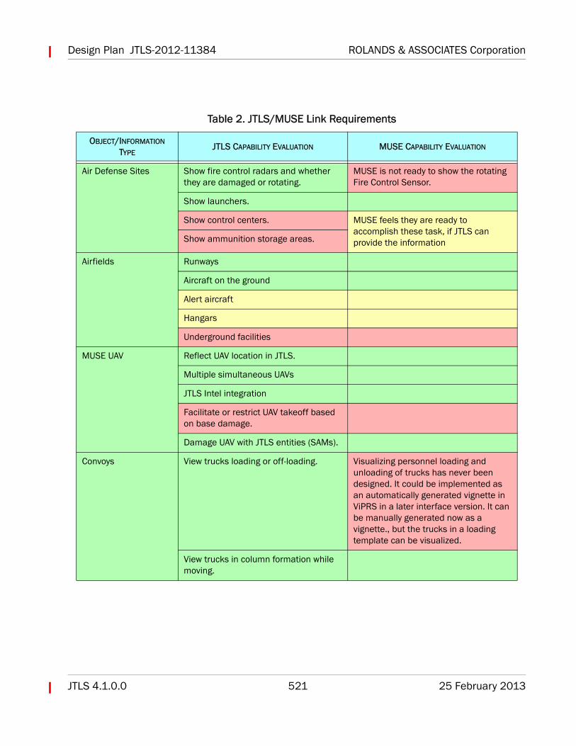
The established Government requirements for this link are summarized in Table 2. Since thiseffort has changed from its initial concept, these requirements are design goals. Capabilities thatcannot be completed by the date of delivery will be postponed to the next JTLS version. Therequirements highlighted green will be implemented as a result of this design; items highlightedyellow may be implemented if time is available; items highlighted red must be postponed to thenext model version. This design document was prepared by the JTLS design team but the MUSEteam has provided some information concerning what they feel is feasible from the MUSE pointof view.
HLA Link Using the JMRM Federation FOM This federation FOM used HLA time management strategies that did not require a heartbeat. The federation was well-received and used, but funding ended prior to enabling MUSE to link using the federation’s unique FOM.
HLA Link Using the JLVC Federation RPR 2.0-based FOM
This federation used HLA in a connectionless mode that required a mandatory heartbeat. Although attempts to execute with MUSE entered initial testing, the heartbeat issue posed a problem again and project alternatives were considered.
HLA Link Using the North Atlantic Treaty Organization (NATO) Training Federation FOM
This FOM was very similar to the JLVC FOM, but was executed in a connected mode. The NTF planned and JTLS successfully demonstrated a link to Virtual Battle Space 2 (VBS2). The issue is that the U.S. Government has no plans to use VBS2 and MUSE has no plans to join the NTF Federation.
Direct Link to MUSE When the JLVC Federation issues became evident, the MUSE and ROLANDS & ASSOCIATES Corporation (R&A) development teams determined that the best solution would re-implement the direct link from JTLS to MUSE. The JTLS Entity Level Server (ELS) resolved the primary issue, discovered many years ago, that involved the MUSE template scheme. This JTLS tool has its own template structure and provides entity level information to models that need entity level detail and propose to integrate with JTLS. This design document describes the details of this new direct link to MUSE.
Table 1. Previously Attempted Links To MUSE (Continued)
ATTEMPT DESCRIPTION WHAT WENT WRONG
Design Plan JTLS-2012-11384 ROLANDS & ASSOCIATES Corporation
JTLS 4.1.0.0 521 25 February 2013
Table 2. JTLS/MUSE Link Requirements
OBJECT/INFORMATION TYPE
JTLS CAPABILITY EVALUATION MUSE CAPABILITY EVALUATION
Air Defense Sites Show fire control radars and whether they are damaged or rotating.
MUSE is not ready to show the rotating Fire Control Sensor.
Show launchers.
Show control centers. MUSE feels they are ready to accomplish these task, if JTLS can provide the informationShow ammunition storage areas.
Airfields Runways
Aircraft on the ground
Alert aircraft
Hangars
Underground facilities
MUSE UAV Reflect UAV location in JTLS.
Multiple simultaneous UAVs
JTLS Intel integration
Facilitate or restrict UAV takeoff based on base damage.
Damage UAV with JTLS entities (SAMs).
Convoys View trucks loading or off-loading. Visualizing personnel loading and unloading of trucks has never been designed. It could be implemented as an automatically generated vignette in ViPRS in a later interface version. It can be manually generated now as a vignette., but the trucks in a loading template can be visualized.
View trucks in column formation while moving.
ROLANDS & ASSOCIATES Corporation Design Plan JTLS-2012-11384
25 February 2013 522 JTLS 4.1.0.0
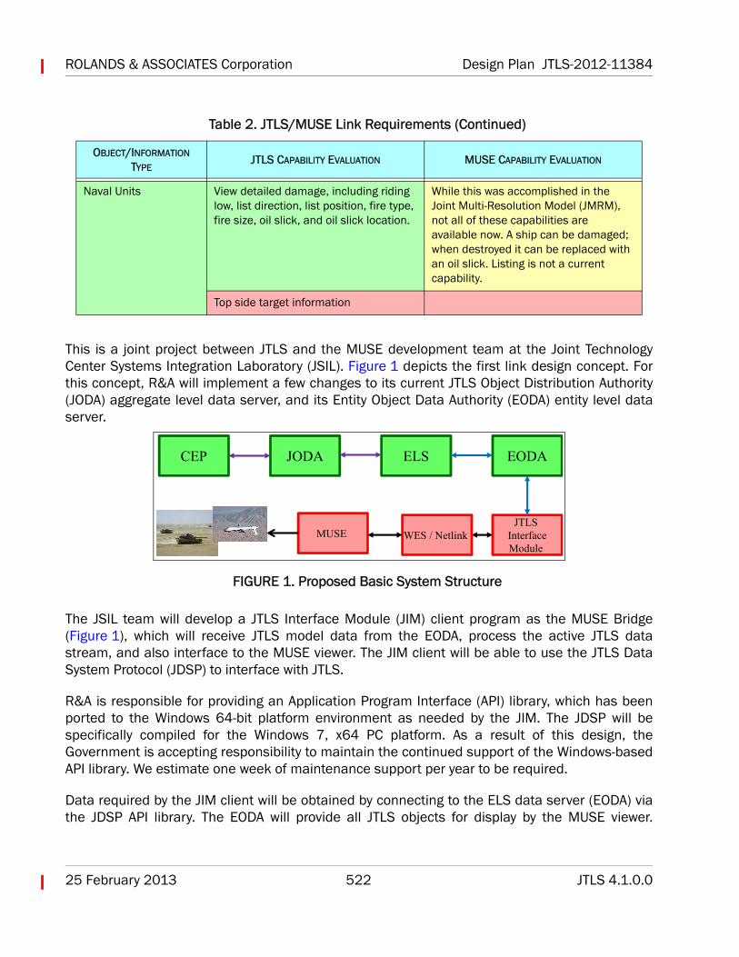
This is a joint project between JTLS and the MUSE development team at the Joint TechnologyCenter Systems Integration Laboratory (JSIL). Figure 1 depicts the first link design concept. Forthis concept, R&A will implement a few changes to its current JTLS Object Distribution Authority(JODA) aggregate level data server, and its Entity Object Data Authority (EODA) entity level dataserver.
FIGURE 1. Proposed Basic System Structure
The JSIL team will develop a JTLS Interface Module (JIM) client program as the MUSE Bridge(Figure 1), which will receive JTLS model data from the EODA, process the active JTLS datastream, and also interface to the MUSE viewer. The JIM client will be able to use the JTLS DataSystem Protocol (JDSP) to interface with JTLS.
R&A is responsible for providing an Application Program Interface (API) library, which has beenported to the Windows 64-bit platform environment as needed by the JIM. The JDSP will bespecifically compiled for the Windows 7, x64 PC platform. As a result of this design, theGovernment is accepting responsibility to maintain the continued support of the Windows-basedAPI library. We estimate one week of maintenance support per year to be required.
Data required by the JIM client will be obtained by connecting to the ELS data server (EODA) viathe JDSP API library. The EODA will provide all JTLS objects for display by the MUSE viewer.
Naval Units View detailed damage, including riding low, list direction, list position, fire type, fire size, oil slick, and oil slick location.
While this was accomplished in the Joint Multi-Resolution Model (JMRM), not all of these capabilities are available now. A ship can be damaged; when destroyed it can be replaced with an oil slick. Listing is not a current capability.
Top side target information
Table 2. JTLS/MUSE Link Requirements (Continued)
OBJECT/INFORMATION TYPE
JTLS CAPABILITY EVALUATION MUSE CAPABILITY EVALUATION
CEP JODA ELS EODA
JTLS InterfaceModule
WES / NetlinkMUSE
Design Plan JTLS-2012-11384 ROLANDS & ASSOCIATES Corporation
JTLS 4.1.0.0 523 25 February 2013
Providing these data from the EODA is a currently available capability. Therefore, the JIM clientmust only receive and process the data containers.
For other proposed features, the EODA must be improved to allow orders and messages to beexchanged between JTLS and the JIM client. These new data exchange mechanisms will be usedto provide updates of the MUSE-controlled UAVs to the JTLS model and return weapon fireparameters to MUSE when a JTLS-owned Air Defense site fires on the MUSE UAV. Details of thesemechanisms are described in Section 3.1.
The following sections provide details of each design requirement described in Table 2.
3.1 Object Reflection
MUSE must reflect JTLS objects; this is the primary purpose of the MUSE link. JTLS must alsoreflect the game objects owned and controlled by MUSE, specifically the one or more UAVs forwhich generated video is produced.
3.1.1 MUSE Reflections
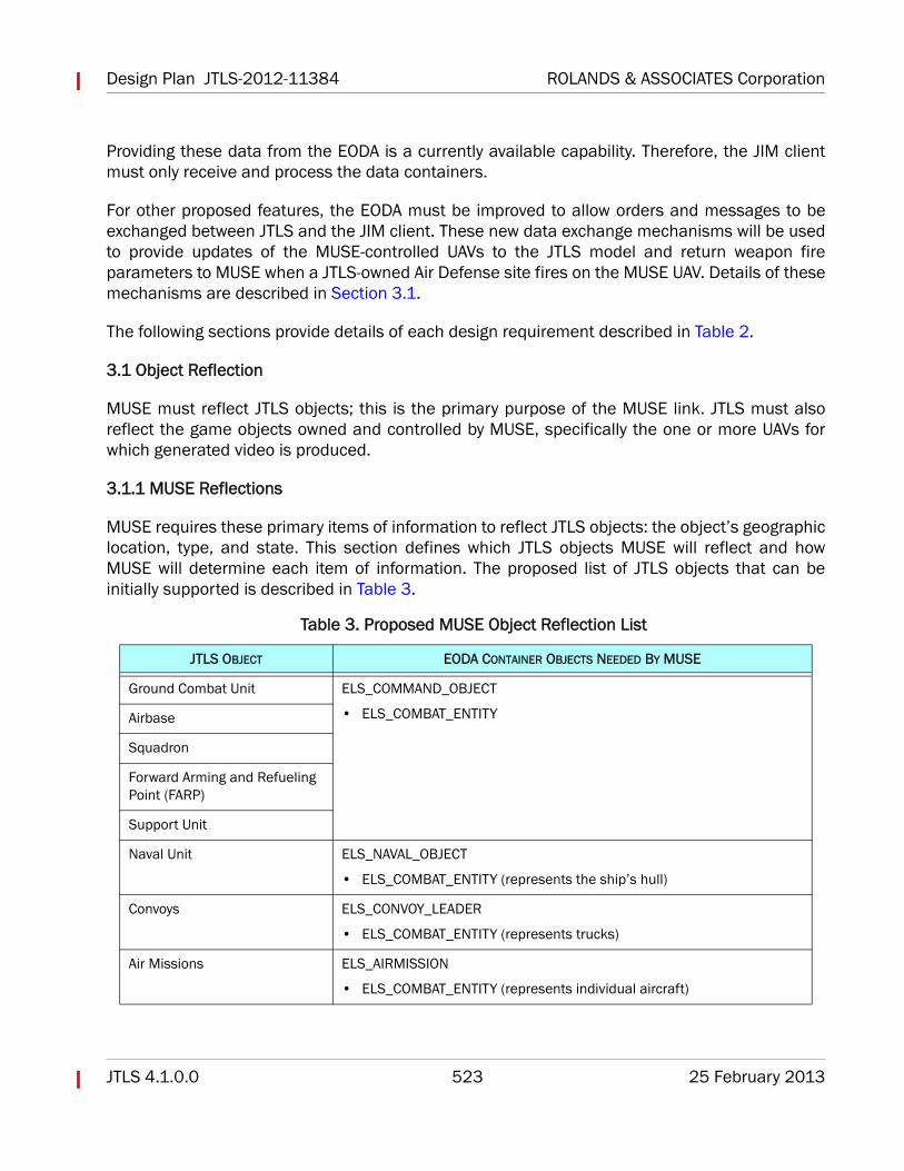
MUSE requires these primary items of information to reflect JTLS objects: the object’s geographiclocation, type, and state. This section defines which JTLS objects MUSE will reflect and howMUSE will determine each item of information. The proposed list of JTLS objects that can beinitially supported is described in Table 3.
Table 3. Proposed MUSE Object Reflection List
JTLS OBJECT EODA CONTAINER OBJECTS NEEDED BY MUSE
Ground Combat Unit ELS_COMMAND_OBJECT
• ELS_COMBAT_ENTITYAirbase
Squadron
Forward Arming and Refueling Point (FARP)
Support Unit
Naval Unit ELS_NAVAL_OBJECT
• ELS_COMBAT_ENTITY (represents the ship’s hull)
Convoys ELS_CONVOY_LEADER
• ELS_COMBAT_ENTITY (represents trucks)
Air Missions ELS_AIRMISSION
• ELS_COMBAT_ENTITY (represents individual aircraft)
ROLANDS & ASSOCIATES Corporation Design Plan JTLS-2012-11384
25 February 2013 524 JTLS 4.1.0.0
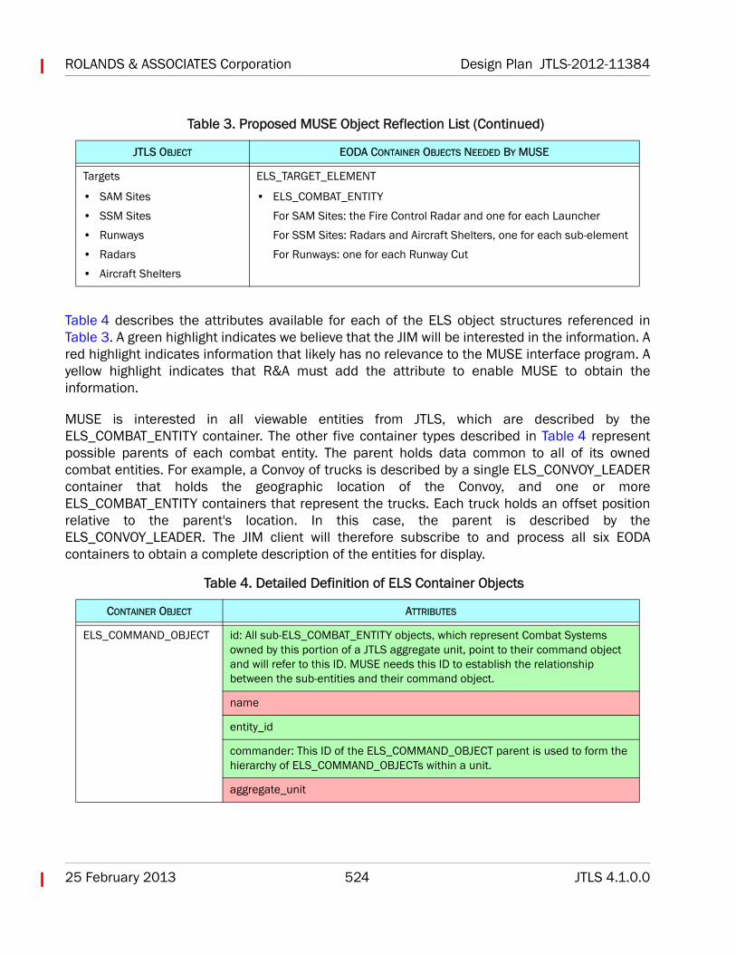
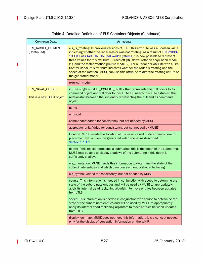
Table 4 describes the attributes available for each of the ELS object structures referenced inTable 3. A green highlight indicates we believe that the JIM will be interested in the information. Ared highlight indicates information that likely has no relevance to the MUSE interface program. Ayellow highlight indicates that R&A must add the attribute to enable MUSE to obtain theinformation.
MUSE is interested in all viewable entities from JTLS, which are described by theELS_COMBAT_ENTITY container. The other five container types described in Table 4 representpossible parents of each combat entity. The parent holds data common to all of its ownedcombat entities. For example, a Convoy of trucks is described by a single ELS_CONVOY_LEADERcontainer that holds the geographic location of the Convoy, and one or moreELS_COMBAT_ENTITY containers that represent the trucks. Each truck holds an offset positionrelative to the parent's location. In this case, the parent is described by theELS_CONVOY_LEADER. The JIM client will therefore subscribe to and process all six EODAcontainers to obtain a complete description of the entities for display.
Targets
• SAM Sites
• SSM Sites
• Runways
• Radars
• Aircraft Shelters
ELS_TARGET_ELEMENT
• ELS_COMBAT_ENTITY
For SAM Sites: the Fire Control Radar and one for each Launcher
For SSM Sites: Radars and Aircraft Shelters, one for each sub-element
For Runways: one for each Runway Cut
Table 4. Detailed Definition of ELS Container Objects
CONTAINER OBJECT ATTRIBUTES
ELS_COMMAND_OBJECT id: All sub-ELS_COMBAT_ENTITY objects, which represent Combat Systems owned by this portion of a JTLS aggregate unit, point to their command object and will refer to this ID. MUSE needs this ID to establish the relationship between the sub-entities and their command object.
name
entity_id
commander: This ID of the ELS_COMMAND_OBJECT parent is used to form the hierarchy of ELS_COMMAND_OBJECTs within a unit.
aggregate_unit
Table 3. Proposed MUSE Object Reflection List (Continued)
JTLS OBJECT EODA CONTAINER OBJECTS NEEDED BY MUSE
Design Plan JTLS-2012-11384 ROLANDS & ASSOCIATES Corporation
JTLS 4.1.0.0 525 25 February 2013
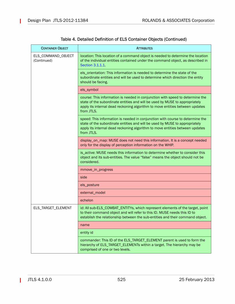
ELS_COMMAND_OBJECT (Continued)
location: This location of a command object is needed to determine the location of the individual entities contained under the command object, as described in Section 3.1.1.1.
els_orientation: This information is needed to determine the state of the subordinate entities and will be used to determine which direction the entity should be facing.
els_symbol
course: This information is needed in conjunction with speed to determine the state of the subordinate entities and will be used by MUSE to appropriately apply its internal dead reckoning algorithm to move entities between updates from JTLS.
speed: This information is needed in conjunction with course to determine the state of the subordinate entities and will be used by MUSE to appropriately apply its internal dead reckoning algorithm to move entities between updates from JTLS.
display_on_map: MUSE does not need this information. It is a concept needed only for the display of perception information on the WHIP.
is_active: MUSE needs this information to determine whether to consider this object and its sub-entities. The value “false” means the object should not be considered.
mmove_in_progress
side
els_posture
external_model
echelon
ELS_TARGET_ELEMENT id: All sub-ELS_COMBAT_ENTITYs, which represent elements of the target, point to their command object and will refer to this ID. MUSE needs this ID to establish the relationship between the sub-entities and their command object.
name
entity id
commander: This ID of the ELS_TARGET_ELEMENT parent is used to form the hierarchy of ELS_TARGET_ELEMENTs within a target. The hierarchy may be comprised of one or two levels.
Table 4. Detailed Definition of ELS Container Objects (Continued)
CONTAINER OBJECT ATTRIBUTES
ROLANDS & ASSOCIATES Corporation Design Plan JTLS-2012-11384
25 February 2013 526 JTLS 4.1.0.0
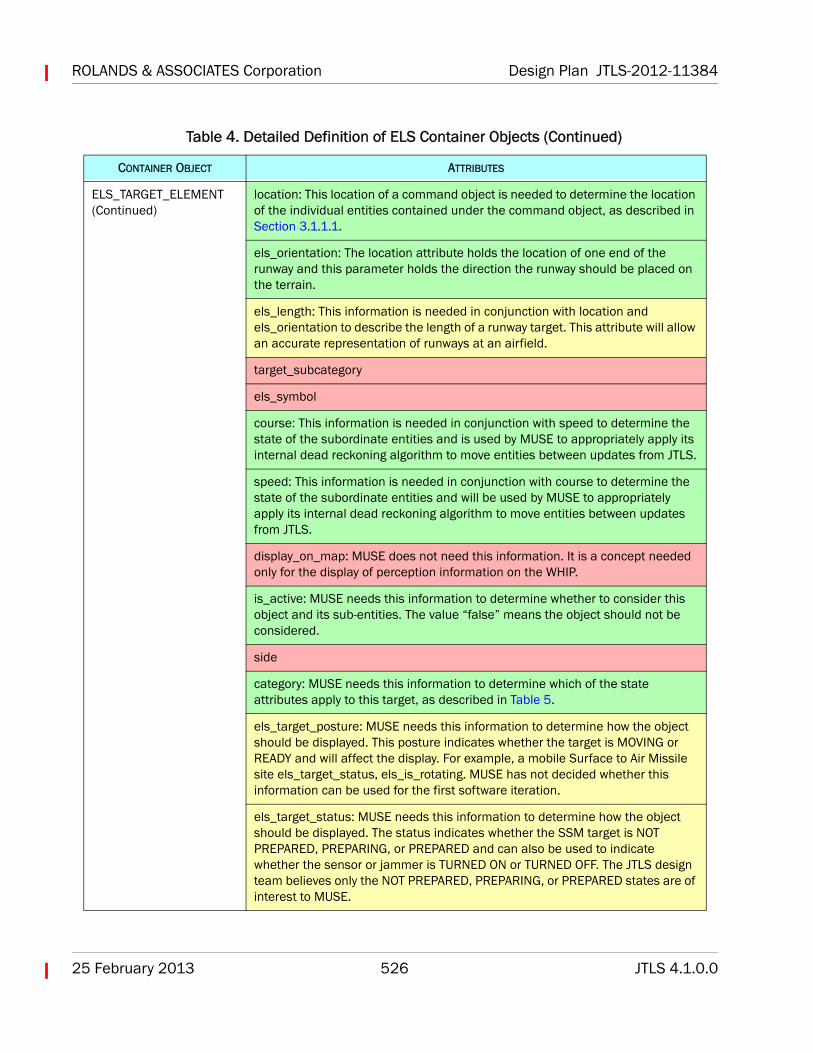
ELS_TARGET_ELEMENT (Continued)
location: This location of a command object is needed to determine the location of the individual entities contained under the command object, as described in Section 3.1.1.1.
els_orientation: The location attribute holds the location of one end of the runway and this parameter holds the direction the runway should be placed on the terrain.
els_length: This information is needed in conjunction with location and els_orientation to describe the length of a runway target. This attribute will allow an accurate representation of runways at an airfield.
target_subcategory
els_symbol
course: This information is needed in conjunction with speed to determine the state of the subordinate entities and is used by MUSE to appropriately apply its internal dead reckoning algorithm to move entities between updates from JTLS.
speed: This information is needed in conjunction with course to determine the state of the subordinate entities and will be used by MUSE to appropriately apply its internal dead reckoning algorithm to move entities between updates from JTLS.
display_on_map: MUSE does not need this information. It is a concept needed only for the display of perception information on the WHIP.
is_active: MUSE needs this information to determine whether to consider this object and its sub-entities. The value “false” means the object should not be considered.
side
category: MUSE needs this information to determine which of the state attributes apply to this target, as described in Table 5.
els_target_posture: MUSE needs this information to determine how the object should be displayed. This posture indicates whether the target is MOVING or READY and will affect the display. For example, a mobile Surface to Air Missile site els_target_status, els_is_rotating. MUSE has not decided whether this information can be used for the first software iteration.
els_target_status: MUSE needs this information to determine how the object should be displayed. The status indicates whether the SSM target is NOT PREPARED, PREPARING, or PREPARED and can also be used to indicate whether the sensor or jammer is TURNED ON or TURNED OFF. The JTLS design team believes only the NOT PREPARED, PREPARING, or PREPARED states are of interest to MUSE.
Table 4. Detailed Definition of ELS Container Objects (Continued)
CONTAINER OBJECT ATTRIBUTES
Design Plan JTLS-2012-11384 ROLANDS & ASSOCIATES Corporation
JTLS 4.1.0.0 527 25 February 2013
ELS_TARGET_ELEMENT (Continued)
els_is_rotating: In previous versions of JTLS, this attribute was a Boolean value indicating whether the radar was or was not rotating. As a result of JTLS-2008-10001 Pass TACELINT To Real World Systems, it is now possible to represent three values for this attribute: Turned off (0), slower rotation acquisition mode (1), and the faster rotation pre-fire mode (2). For a Radar or SAM Site with a Fire Control Radar, this attribute indicates whether the radar is rotating and the speed of the rotation. MUSE can use this attribute to alter the rotating nature of the generated model.
external_model
ELS_NAVAL_OBJECT
This is a new EODA object
id: The single sub-ELS_COMBAT_ENTITY that represents the hull points to its command object and will refer to this ID. MUSE needs this ID to establish the relationship between the sub-entity representing the hull and its command object.
name
entity_id
commander: Added for consistency, but not needed by MUSE
aggregate_unit: Added for consistency, but not needed by MUSE
location: MUSE needs this location of the naval vessel to determine where to place the naval unit on the generated video scene, as described in Section 3.1.1.1.
depth: If this object represents a submarine, this is the depth of the submarine. MUSE may be able to display shadows of the submarine if this depth is sufficiently shallow.
els_orientation: MUSE needs this information to determine the state of the subordinate entities and which direction each entity should be facing.
els_symbol: Added for consistency, but not needed by MUSE
course: This information is needed in conjunction with speed to determine the state of the subordinate entities and will be used by MUSE to appropriately apply its internal dead reckoning algorithm to move entities between updates from JTLS.
speed: This information is needed in conjunction with course to determine the state of the subordinate entities and will be used by MUSE to appropriately apply its internal dead reckoning algorithm to move entities between updates from JTLS.
display_on_map: MUSE does not need this information. It is a concept needed only for the display of perception information on the WHIP.
Table 4. Detailed Definition of ELS Container Objects (Continued)
CONTAINER OBJECT ATTRIBUTES
ROLANDS & ASSOCIATES Corporation Design Plan JTLS-2012-11384
25 February 2013 528 JTLS 4.1.0.0
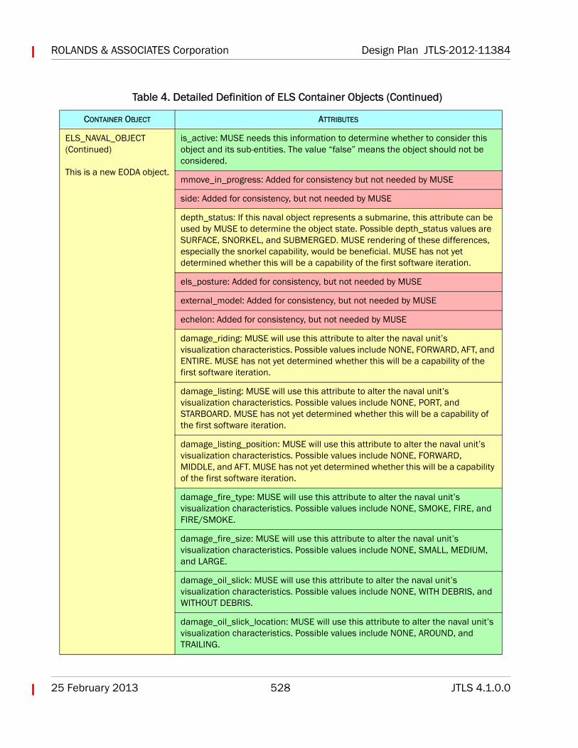
ELS_NAVAL_OBJECT (Continued)
This is a new EODA object.
is_active: MUSE needs this information to determine whether to consider this object and its sub-entities. The value “false” means the object should not be considered.
mmove_in_progress: Added for consistency but not needed by MUSE
side: Added for consistency, but not needed by MUSE
depth_status: If this naval object represents a submarine, this attribute can be used by MUSE to determine the object state. Possible depth_status values are SURFACE, SNORKEL, and SUBMERGED. MUSE rendering of these differences, especially the snorkel capability, would be beneficial. MUSE has not yet determined whether this will be a capability of the first software iteration.
els_posture: Added for consistency, but not needed by MUSE
external_model: Added for consistency, but not needed by MUSE
echelon: Added for consistency, but not needed by MUSE
damage_riding: MUSE will use this attribute to alter the naval unit’s visualization characteristics. Possible values include NONE, FORWARD, AFT, and ENTIRE. MUSE has not yet determined whether this will be a capability of the first software iteration.
damage_listing: MUSE will use this attribute to alter the naval unit’s visualization characteristics. Possible values include NONE, PORT, and STARBOARD. MUSE has not yet determined whether this will be a capability of the first software iteration.
damage_listing_position: MUSE will use this attribute to alter the naval unit’s visualization characteristics. Possible values include NONE, FORWARD, MIDDLE, and AFT. MUSE has not yet determined whether this will be a capability of the first software iteration.
damage_fire_type: MUSE will use this attribute to alter the naval unit’s visualization characteristics. Possible values include NONE, SMOKE, FIRE, and FIRE/SMOKE.
damage_fire_size: MUSE will use this attribute to alter the naval unit’s visualization characteristics. Possible values include NONE, SMALL, MEDIUM, and LARGE.
damage_oil_slick: MUSE will use this attribute to alter the naval unit’s visualization characteristics. Possible values include NONE, WITH DEBRIS, and WITHOUT DEBRIS.
damage_oil_slick_location: MUSE will use this attribute to alter the naval unit’s visualization characteristics. Possible values include NONE, AROUND, and TRAILING.
Table 4. Detailed Definition of ELS Container Objects (Continued)
CONTAINER OBJECT ATTRIBUTES
Design Plan JTLS-2012-11384 ROLANDS & ASSOCIATES Corporation
JTLS 4.1.0.0 529 25 February 2013
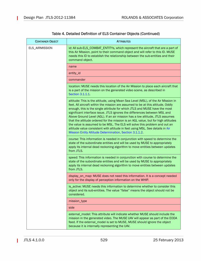
ELS_AIRMISSION id: All sub-ELS_COMBAT_ENTITYs, which represent the aircraft that are a part of this Air Mission, point to their command object and will refer to this ID. MUSE needs this ID to establish the relationship between the sub-entities and their command object.
name
entity_id
commander
location: MUSE needs this location of the Air Mission to place each aircraft that is a part of the mission on the generated video scene, as described in Section 3.1.1.1.
altitude: This is the altitude, using Mean Sea Level (MSL), of the Air Mission in feet. All aircraft within the mission are assumed to be at this altitude. Oddly enough, this is the single attribute for which JTLS and MUSE have the most significant interface issue. JTLS ignores the differences between MSL and Above Ground Level (AGL). If an air mission has a low altitude, JTLS assumes that the altitude ordered for the mission is an AGL value, but for high altitudes the value is assumed to be MSL. The ELS will solve this problem and out an altitude value consistent with altitude in feet using MSL. See details in Air Mission Entity Altitude Determination, Section 3.1.1.2.
course: This information is needed in conjunction with speed to determine the state of the subordinate entities and will be used by MUSE to appropriately apply its internal dead reckoning algorithm to move entities between updates from JTLS.
speed: This information is needed in conjunction with course to determine the state of the subordinate entities and will be used by MUSE to appropriately apply its internal dead reckoning algorithm to move entities between updates from JTLS.
display_on_map: MUSE does not need this information. It is a concept needed only for the display of perception information on the WHIP.
is_active: MUSE needs this information to determine whether to consider this object and its sub-entities. The value “false” means the object should not be considered.
mission_type
side
external_model: This attribute will indicate whether MUSE should include the mission in the generated video. The MUSE UAV will appear as part of the EODA feed. If the external_model is set to MUSE, MUSE should ignore the object because it is internally representing the UAV.
Table 4. Detailed Definition of ELS Container Objects (Continued)
CONTAINER OBJECT ATTRIBUTES
ROLANDS & ASSOCIATES Corporation Design Plan JTLS-2012-11384
25 February 2013 530 JTLS 4.1.0.0
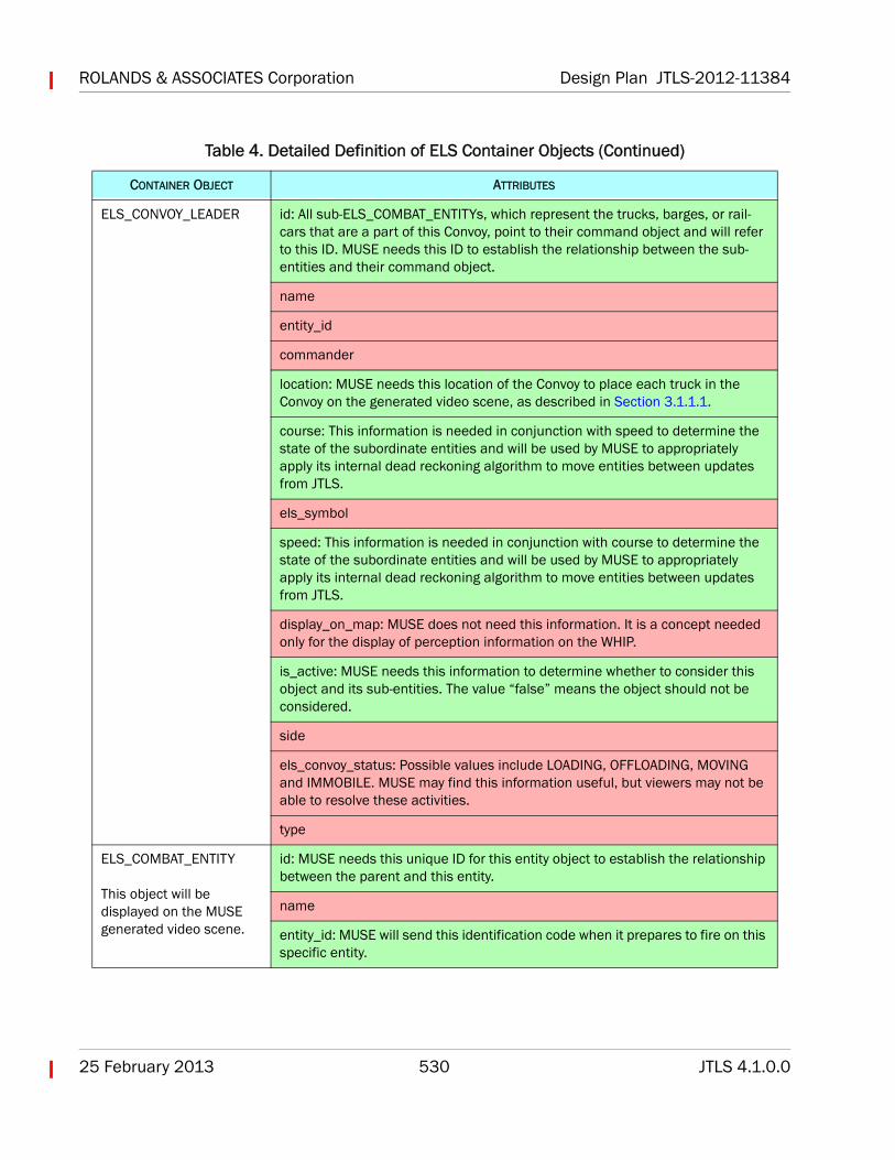
ELS_CONVOY_LEADER id: All sub-ELS_COMBAT_ENTITYs, which represent the trucks, barges, or rail-cars that are a part of this Convoy, point to their command object and will refer to this ID. MUSE needs this ID to establish the relationship between the sub-entities and their command object.
name
entity_id
commander
location: MUSE needs this location of the Convoy to place each truck in the Convoy on the generated video scene, as described in Section 3.1.1.1.
course: This information is needed in conjunction with speed to determine the state of the subordinate entities and will be used by MUSE to appropriately apply its internal dead reckoning algorithm to move entities between updates from JTLS.
els_symbol
speed: This information is needed in conjunction with course to determine the state of the subordinate entities and will be used by MUSE to appropriately apply its internal dead reckoning algorithm to move entities between updates from JTLS.
display_on_map: MUSE does not need this information. It is a concept needed only for the display of perception information on the WHIP.
is_active: MUSE needs this information to determine whether to consider this object and its sub-entities. The value “false” means the object should not be considered.
side
els_convoy_status: Possible values include LOADING, OFFLOADING, MOVING and IMMOBILE. MUSE may find this information useful, but viewers may not be able to resolve these activities.
type
ELS_COMBAT_ENTITY
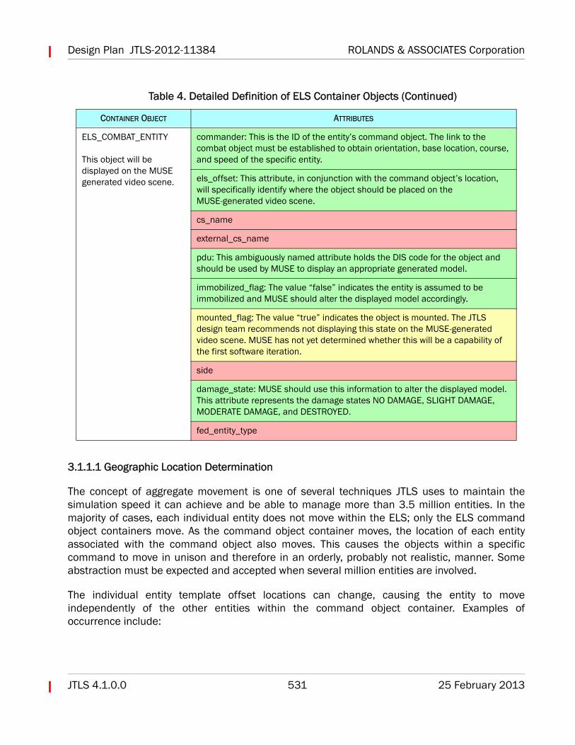
This object will be displayed on the MUSE generated video scene.
id: MUSE needs this unique ID for this entity object to establish the relationship between the parent and this entity.
name
entity_id: MUSE will send this identification code when it prepares to fire on this specific entity.
Table 4. Detailed Definition of ELS Container Objects (Continued)
CONTAINER OBJECT ATTRIBUTES
Design Plan JTLS-2012-11384 ROLANDS & ASSOCIATES Corporation
JTLS 4.1.0.0 531 25 February 2013
3.1.1.1 Geographic Location Determination
The concept of aggregate movement is one of several techniques JTLS uses to maintain thesimulation speed it can achieve and be able to manage more than 3.5 million entities. In themajority of cases, each individual entity does not move within the ELS; only the ELS commandobject containers move. As the command object container moves, the location of each entityassociated with the command object also moves. This causes the objects within a specificcommand to move in unison and therefore in an orderly, probably not realistic, manner. Someabstraction must be expected and accepted when several million entities are involved.
The individual entity template offset locations can change, causing the entity to moveindependently of the other entities within the command object container. Examples ofoccurrence include:
ELS_COMBAT_ENTITY
This object will be displayed on the MUSE generated video scene.
commander: This is the ID of the entity’s command object. The link to the combat object must be established to obtain orientation, base location, course, and speed of the specific entity.
els_offset: This attribute, in conjunction with the command object’s location, will specifically identify where the object should be placed on the MUSE-generated video scene.
cs_name
external_cs_name
pdu: This ambiguously named attribute holds the DIS code for the object and should be used by MUSE to display an appropriate generated model.
immobilized_flag: The value “false” indicates the entity is assumed to be immobilized and MUSE should alter the displayed model accordingly.
mounted_flag: The value “true” indicates the object is mounted. The JTLS design team recommends not displaying this state on the MUSE-generated video scene. MUSE has not yet determined whether this will be a capability of the first software iteration.
side
damage_state: MUSE should use this information to alter the displayed model. This attribute represents the damage states NO DAMAGE, SLIGHT DAMAGE, MODERATE DAMAGE, and DESTROYED.
fed_entity_type
Table 4. Detailed Definition of ELS Container Objects (Continued)
CONTAINER OBJECT ATTRIBUTES
ROLANDS & ASSOCIATES Corporation Design Plan JTLS-2012-11384
25 February 2013 532 JTLS 4.1.0.0
• When a Combat System is destroyed, other systems of the same type may move into thetemplate location of the destroyed system. The speed with which this occurs depends onthe characteristics of the entity and the distance between the entity’s previous templatelocation and the new location. This capability is a long-term ELS goal that is currently onlypartially implemented.
• An aggregate unit that changes posture within JTLS may change the underlying template.The ELS represents four different templates for every type of unit represented in the JTLSdatabase: Defend, Move, Attack Mounted, and Attack Dismounted. If the underlyingtemplate changes, each entity moves independently to its newly assigned templatelocation.
Consequently, MUSE must alter the location of an entity as follows:
• Each time a command object container changes its location, all sub-entities must havetheir location altered.
• Each time the location offset attribute changes on the ELS_COMBAT_ENTITY, the locationof that specific entity must change.
The JTLS development team will deliver code that demonstrates to the MUSE development teamhow to use the location value of a command object container and the offset attribute of anELS_COMBAT_ENTITY to create a latitude and longitude suitable for use with the MUSE videoscene generation capability.
The integration team has one concern about scene generation realism, when the individualELS_COMBAT_ENTITY are moving independently. When these entities are moving as part of theirCommand Object, the object has information concerning the course, speed, and destination ofthe Command Object. MUSE can use this information to internally accomplish its “deadreckoning” algorithm to insure that the entity moves smoothly in the generated display.
This needed “dead reckoning” information is not available on the ELS_COMBAT_ENTITY whenindividual entities are moving. Their offset locations are being updated periodically by the ELSuntil they occupy their new template locations. Although this periodic update time is configurable,the team believes that the typical 3 to 5 second update time may prove to lead to an unrealisticjumping representation of these entities in MUSE.
The impact of this will be evaluated during the testing of this initial capability and may need to bea high priority future improvement.
3.1.1.2 Air Mission Entity Altitude Determination
As mentioned, there is a disconnect between JTLS and MUSE when it comes to the altitude atwhich an air mission is flying. MUSE expects all altitudes to be in MSL and JTLS is not well
Design Plan JTLS-2012-11384 ROLANDS & ASSOCIATES Corporation
JTLS 4.1.0.0 533 25 February 2013
defined concerning the meaning of the JTLS model generated altitude parameter. The ELS willcorrect this problem and MUSE can consider the altitude attribute of ELS_AIRMISSION CommandObject to be in MSL.
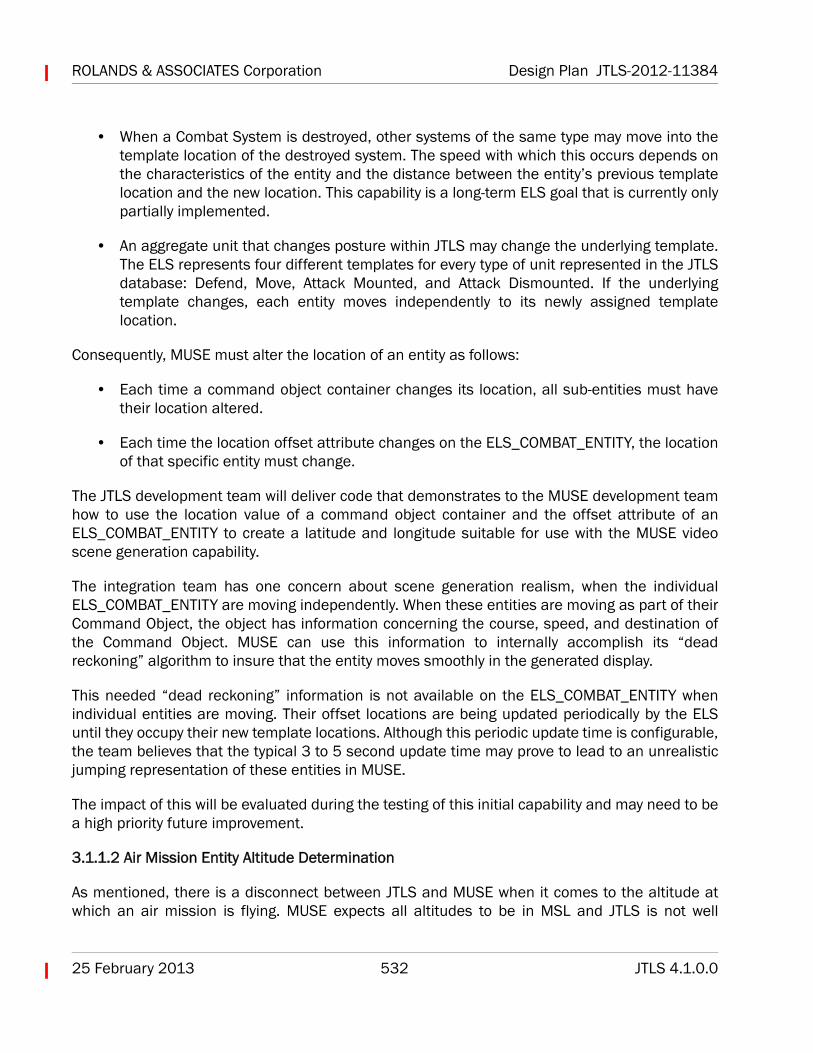
The ELS will be use the algorithm shown in Figure 2 to compute an appropriate ELS AIRMISSIONaltitude attribute. This algorithm will require that the ELS read in and hold onto the elevation ineach JTLS represented terrain region.
FIGURE 2. EODA Air Mission Altitude Determination
3.1.1.3 Entity Type Determination
MUSE will display only the ELS_COMBAT_ENTITY. The “pdu” attribute will hold the DIS code forthe entity. To facilitate ensuring that MUSE has all of the models available to display theseentities, the JTLS database build procedure will create a list of DIS codes used for any specificscenario. Also, the R&A design team recommends that MUSE be easily configurable concerningthe display of an ELS_COMBAT_ENTITY that has a DIS code of 0.0.0.0.0.0.0. During testing, thedisplay of these entities will help debug the database, but would be inappropriate during actualexercise use.
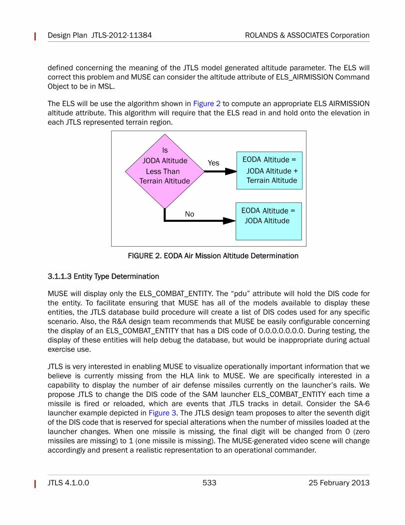
JTLS is very interested in enabling MUSE to visualize operationally important information that webelieve is currently missing from the HLA link to MUSE. We are specifically interested in acapability to display the number of air defense missiles currently on the launcher’s rails. Wepropose JTLS to change the DIS code of the SAM launcher ELS_COMBAT_ENTITY each time amissile is fired or reloaded, which are events that JTLS tracks in detail. Consider the SA-6launcher example depicted in Figure 3. The JTLS design team proposes to alter the seventh digitof the DIS code that is reserved for special alterations when the number of missiles loaded at thelauncher changes. When one missile is missing, the final digit will be changed from 0 (zeromissiles are missing) to 1 (one missile is missing). The MUSE-generated video scene will changeaccordingly and present a realistic representation to an operational commander.
IsJODA Altitude
Terrain AltitudeLess Than
Yes
No
EODA Altitude =JODA Altitude +Terrain Altitude
EODA Altitude =JODA Altitude
ROLANDS & ASSOCIATES Corporation Design Plan JTLS-2012-11384
25 February 2013 534 JTLS 4.1.0.0
FIGURE 3. Altering DIS Code Based On JTLS Model Information
3.1.1.4 Entity State Determination
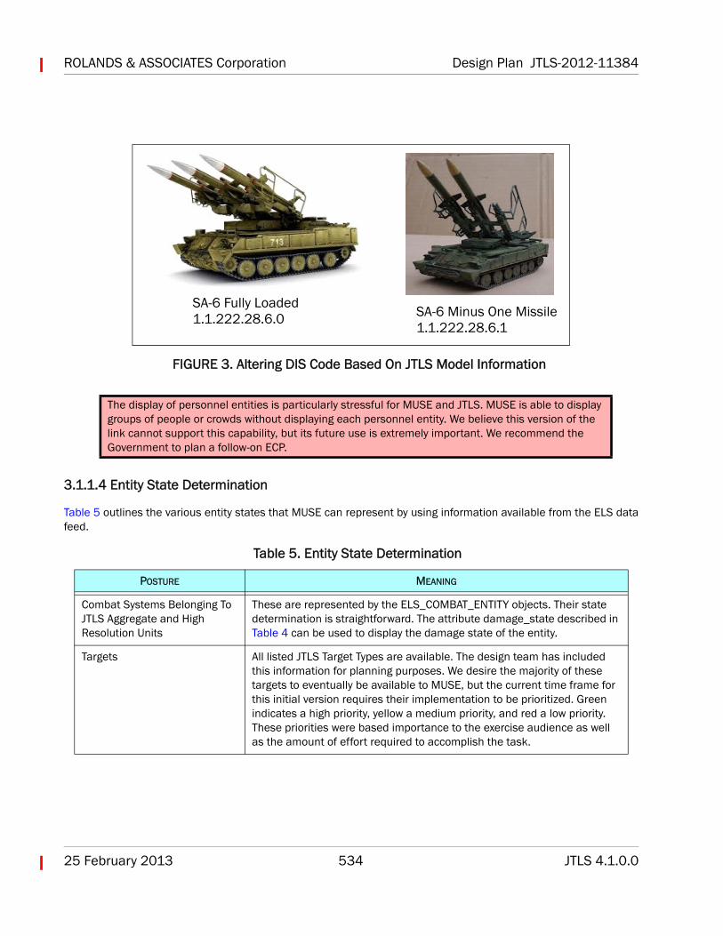
Table 5 outlines the various entity states that MUSE can represent by using information available from the ELS datafeed.
The display of personnel entities is particularly stressful for MUSE and JTLS. MUSE is able to display groups of people or crowds without displaying each personnel entity. We believe this version of the link cannot support this capability, but its future use is extremely important. We recommend the Government to plan a follow-on ECP.
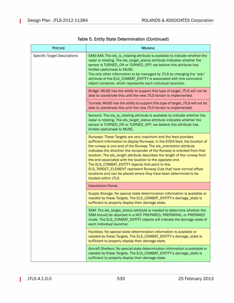
Table 5. Entity State Determination
POSTURE MEANING
Combat Systems Belonging To JTLS Aggregate and High Resolution Units
These are represented by the ELS_COMBAT_ENTITY objects. Their state determination is straightforward. The attribute damage_state described in Table 4 can be used to display the damage state of the entity.
Targets All listed JTLS Target Types are available. The design team has included this information for planning purposes. We desire the majority of these targets to eventually be available to MUSE, but the current time frame for this initial version requires their implementation to be prioritized. Green indicates a high priority, yellow a medium priority, and red a low priority. These priorities were based importance to the exercise audience as well as the amount of effort required to accomplish the task.
SA-6 Fully Loaded1.1.222.28.6.0 SA-6 Minus One Missile
1.1.222.28.6.1
Design Plan JTLS-2012-11384 ROLANDS & ASSOCIATES Corporation
JTLS 4.1.0.0 535 25 February 2013
Specific Target Descriptions SAM/AAA: The els_is_rotating attribute is available to indicate whether the radar is rotating. The els_target_status attribute indicates whether the sensor is TURNED_ON or TURNED_OFF; we believe this attribute has limited usefulness to MUSE.The only other information to be managed by JTLS by changing the “pdu” attribute of the ELS_COMBAT_ENTITY is associated with this command object container, which represents each individual launcher.
Bridge: MUSE has the ability to support this type of target, JTLS will not be able to coordinate this until the new JTLS terrain is implemented.
Tunnels: MUSE has the ability to support this type of target, JTLS will not be able to coordinate this until the new JTLS terrain is implemented.
Sensors: The els_is_rotating attribute is available to indicate whether the radar is rotating. The els_target_status attribute indicates whether the sensor is TURNED_ON or TURNED_OFF; we believe this attribute has limited usefulness to MUSE.
Runways: These Targets are very important and the feed provides sufficient information to display Runways. In the EODA feed, the location of the runway is one end of the Runway. The els_orientation attribute indicates the direction the remainder of the Runway is oriented from that location. The els_length attribute describes the length of the runway from the end associated with the location to the opposite end.The ELS_COMBAT_ENTITY objects that point to this ELS_TARGET_ELEMENT represent Runway Cuts that have normal offset locations and can be placed where they have been determined to be located within JTLS.
Interdiction Points
Supply Storage: No special state determination information is available or needed by these Targets. The ELS_COMBAT_ENTITY’s damage_state is sufficient to properly display their damage state.
SSM: The els_target_status attribute is needed to determine whether the SSM should be depicted in a NOT PREPARED, PREPARING, or PREPARED mode. The ELS_COMBAT_ENTITY objects will indicate the damage state of each individual launcher.
Facilities: No special state determination information is available or needed by these Targets. The ELS_COMBAT_ENTITY’s damage_state is sufficient to properly display their damage state.
Aircraft Shelters: No special state determination information is available or needed by these Targets. The ELS_COMBAT_ENTITY’s damage_state is sufficient to properly display their damage state.
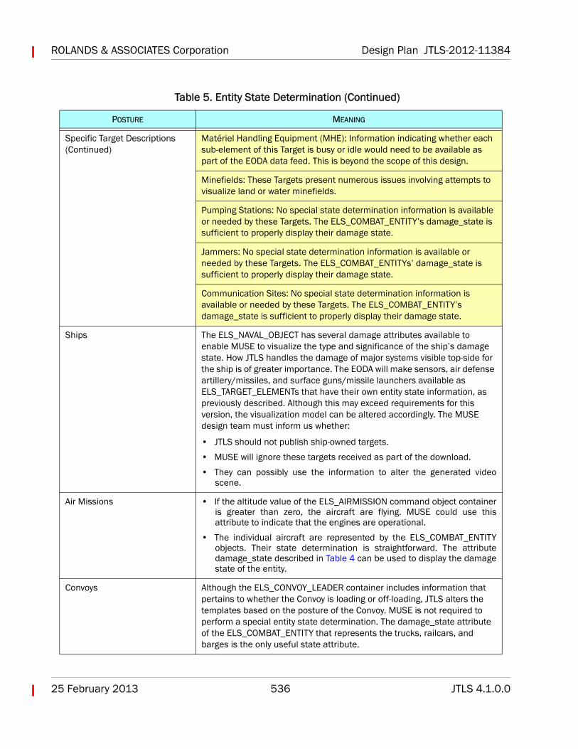
Table 5. Entity State Determination (Continued)
POSTURE MEANING
ROLANDS & ASSOCIATES Corporation Design Plan JTLS-2012-11384
25 February 2013 536 JTLS 4.1.0.0
Specific Target Descriptions (Continued)
Matériel Handling Equipment (MHE): Information indicating whether each sub-element of this Target is busy or idle would need to be available as part of the EODA data feed. This is beyond the scope of this design.
Minefields: These Targets present numerous issues involving attempts to visualize land or water minefields.
Pumping Stations: No special state determination information is available or needed by these Targets. The ELS_COMBAT_ENTITY’s damage_state is sufficient to properly display their damage state.
Jammers: No special state determination information is available or needed by these Targets. The ELS_COMBAT_ENTITYs’ damage_state is sufficient to properly display their damage state.
Communication Sites: No special state determination information is available or needed by these Targets. The ELS_COMBAT_ENTITY’s damage_state is sufficient to properly display their damage state.
Ships The ELS_NAVAL_OBJECT has several damage attributes available to enable MUSE to visualize the type and significance of the ship’s damage state. How JTLS handles the damage of major systems visible top-side for the ship is of greater importance. The EODA will make sensors, air defense artillery/missiles, and surface guns/missile launchers available as ELS_TARGET_ELEMENTs that have their own entity state information, as previously described. Although this may exceed requirements for this version, the visualization model can be altered accordingly. The MUSE design team must inform us whether:
• JTLS should not publish ship-owned targets.
• MUSE will ignore these targets received as part of the download.
• They can possibly use the information to alter the generated videoscene.
Air Missions • If the altitude value of the ELS_AIRMISSION command object containeris greater than zero, the aircraft are flying. MUSE could use thisattribute to indicate that the engines are operational.
• The individual aircraft are represented by the ELS_COMBAT_ENTITYobjects. Their state determination is straightforward. The attributedamage_state described in Table 4 can be used to display the damagestate of the entity.
Convoys Although the ELS_CONVOY_LEADER container includes information that pertains to whether the Convoy is loading or off-loading, JTLS alters the templates based on the posture of the Convoy. MUSE is not required to perform a special entity state determination. The damage_state attribute of the ELS_COMBAT_ENTITY that represents the trucks, railcars, and barges is the only useful state attribute.
Table 5. Entity State Determination (Continued)
POSTURE MEANING
Design Plan JTLS-2012-11384 ROLANDS & ASSOCIATES Corporation
JTLS 4.1.0.0 537 25 February 2013
3.1.2 JTLS Reflection of External Aircraft (UAV Missions)
All aircraft owned by MUSE will be in the JTLS scenario and available from the start of the game.These JTLS UAVs can be flown by MUSE when the JIM client is connected. If the JIM is notconnected, JTLS can assume ownership of the Squadron and subsequently fly the UAVs withinJTLS without using MUSE.
The issues must be addressed for the reflection to work:
• Launching the UAV
• Reflecting the location of the UAV
• Completion of the Air Mission or landing of the UAV
If a UAV is moved on the ground from one location to another, MUSE has no reason to pass thisinformation to JTLS. For this version of the interface, JTLS is interested only in reflecting the UAVwhile it is flying.
All Squadrons from which MUSE will fly UAVs must be defined in the JTLS scenario database.When JTLS is executing, the ELS will create an entity for each aircraft owned by MUSE. JTLS viewsthese entities as externally controlled by MUSE. At the start of the game, MUSE must discoverthese aircraft entities from their object data (type COMBAT_SYSTEM_ENTITY), which are availableon the EODA. When MUSE discovers these entities, they will thus know the unique entity IDs thatare used to identify and interact with the ELS through the orders further described.
Each of these processes is described in this section.
3.1.2.1 Launching the UAV
To tell JTLS that a UAV is launching, the JIM must send an ELS order to the EODA that is thenpassed in succession to the ELS, the JODA, and to JTLS for processing. The data flow depicted inFigure 1 is therefore bi-directional.
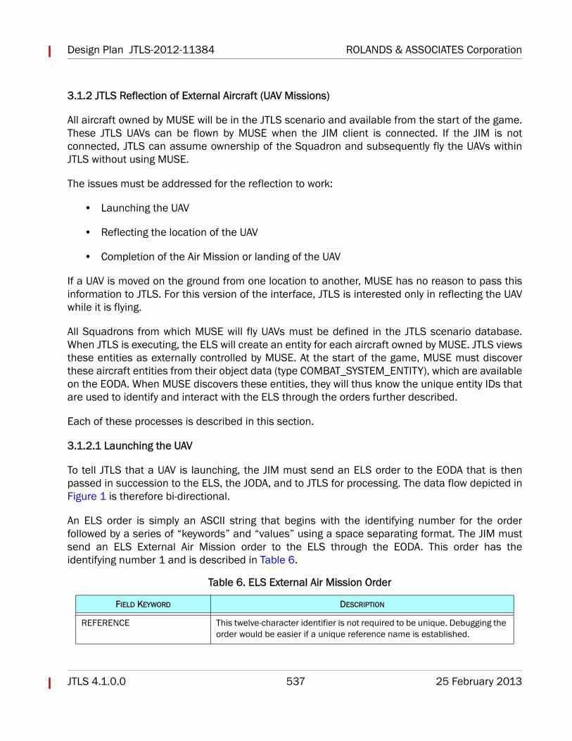
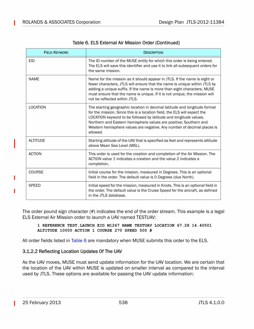
An ELS order is simply an ASCII string that begins with the identifying number for the orderfollowed by a series of “keywords” and “values” using a space separating format. The JIM mustsend an ELS External Air Mission order to the ELS through the EODA. This order has theidentifying number 1 and is described in Table 6.
Table 6. ELS External Air Mission Order
FIELD KEYWORD DESCRIPTION
REFERENCE This twelve-character identifier is not required to be unique. Debugging the order would be easier if a unique reference name is established.
ROLANDS & ASSOCIATES Corporation Design Plan JTLS-2012-11384
25 February 2013 538 JTLS 4.1.0.0
The order pound sign character (#) indicates the end of the order stream. This example is a legalELS External Air Mission order to launch a UAV named TESTUAV:
1 REFERENCE TEST.LAUNCH EID M1267 NAME TESTUAV LOCATION 67.28 14.40501 ALTITUDE 10000 ACTION 1 COURSE 270 SPEED 500 #
All order fields listed in Table 6 are mandatory when MUSE submits this order to the ELS.
3.1.2.2 Reflecting Location Updates Of The UAV
As the UAV moves, MUSE must send update information for the UAV location. We are certain thatthe location of the UAV within MUSE is updated on smaller interval as compared to the intervalused by JTLS. These options are available for passing the UAV update information:
EID The ID number of the MUSE entity for which this order is being entered. The ELS will save this identifier and use it to link all subsequent orders for the same mission.
NAME Name for the mission as it should appear in JTLS. If the name is eight or fewer characters, JTLS will ensure that the name is unique within JTLS by adding a unique suffix. If the name is more than eight characters, MUSE must ensure that the name is unique. If it is not unique, the mission will not be reflected within JTLS.
LOCATION The starting geographic location in decimal latitude and longitude format for the mission. Since this is a location field, the ELS will expect the LOCATION keyword to be followed by latitude and longitude values. Northern and Eastern hemisphere values are positive; Southern and Western hemisphere values are negative. Any number of decimal places is allowed.
ALTITUDE Starting altitude of the UAV that is specified as feet and represents altitude above Mean Sea Level (MSL).
ACTION This order is used for the creation and completion of the Air Mission. The ACTION value 1 indicates a creation and the value 2 indicates a completion.
COURSE Initial course for the mission, measured in Degrees. This is an optional field in the order. The default value is 0 Degrees (due North).
SPEED Initial speed for the mission, measured in Knots. This is an optional field in the order. The default value is the Cruise Speed for the aircraft, as defined in the JTLS database.
Table 6. ELS External Air Mission Order (Continued)
FIELD KEYWORD DESCRIPTION
Design Plan JTLS-2012-11384 ROLANDS & ASSOCIATES Corporation
JTLS 4.1.0.0 539 25 February 2013
• Distance Option - If MUSE decides to use this option, the UAV should send an update eachtime it moves 1 KM.
• Time Option - If MUSE decides to use this option, we recommend updating the UAVlocation every 15 seconds.
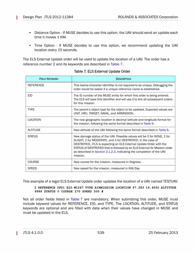
The ELS External Update order will be used to update the location of a UAV. The order has a reference number 2 and its keywords are described in Table 7.
This example of a legal ELS External Update order updates the location of a UAV named TESTUAV:
2 REFERENCE UPD1 EID M1267 TYPE AIRMISSION LOCATION 67.283 14.4052 ALTITUDE 9999 STATUS 0 COURSE 270 SPEED 500 #
Not all order fields listed in Table 7 are mandatory. When submitting this order, MUSE mustinclude keyword values for REFERENCE, EID, and TYPE. The LOCATION, ALTITUDE, and STATUSkeywords are optional and are filled with data when their values have changed in MUSE andmust be updated in the ELS.
Table 7. ELS External Update Order
FIELD KEYWORD DESCRIPTION
REFERENCE This twelve-character identifier is not required to be unique. Debugging the order would be easier if a unique reference name is established.
EID The ID number of the MUSE entity for which this order is being entered. The ELS will save this identifier and will use it to link all subsequent orders for this mission.
TYPE The parent’s object type for the object to be updated. Expected values are UNIT, HRU, TARGET, NAVAL, and AIRMISSION.
LOCATION The new geographic location in decimal latitude and longitude format for the mission, following the same format described in Table 6.
ALTITUDE New altitude of the UAV following the same format described in Table 6.
STATUS New damage status of the UAV. Possible values will be 0 for NONE, 1 for SLIGHT, 2 for MODERATE, and 3 for DESTROYED. In the case of DESTROYED, JTLS is expecting an ELS External Update Order with the STATUS of DESTROYED that is followed by an ELS External Air Mission order as described in Section 3.1.2.3, indicating the completion of the UAV mission.
COURSE New course for the mission, measured in Degrees.
SPEED New speed for the mission, measured in KM/Day
ROLANDS & ASSOCIATES Corporation Design Plan JTLS-2012-11384
25 February 2013 540 JTLS 4.1.0.0
3.1.2.3 Landing or Destroying the UAV
When a UAV lands or is destroyed, a second ELS Air Mission order must be sent from MUSE. Thisorder matches the format described in Section 3.1.2.1, but the NAME and ALTITUDE fields arenot required. Also, the ACTION field should have the value 2 to indicate this is the most recentorder for the Air Mission. In the case of a landing UAV, the entity ID can be used again, but a newELS Air Mission order must be sent that indicates the UAV has taken off again.
This example of a legal ELS Air Mission order indicates that the UAV named TESTUAV has landed:
1 REFERENCE 1267LAND EID M1267 LOCATION 67.283 14.4052 ACTION 2 #
3.1.3 MUSE Reflection of JTLS Weapon Fire and Munition Detonations
MUSE is interested in knowledge about the firing of weapons within JTLS and their detonation forthese reasons:
• MUSE can place the explosion on the generated video scene if it knows the exact locationof a detonation, and also may be able to display a “flash” for the firing location.
• If the object that is being hit is the MUSE UAV, MUSE must assess the UAV damage andreturn the results to JTLS.
The CEP currently sends a Weapon Firing Interaction message and a Weapon DetonationInteraction message for publication on the federation HLA feed via the JTLS HLA InterfaceProgram (HIP). This information is important to MUSE, but does not contain the entity levelinformation required by MUSE. The JTLS design team has decided that the ELS will subscribe tothese current CEP messages and pass a modified version of the messages to MUSE via theEODA.
On the EODA, these messages will continue to be known as HIP Interaction Event objects,although they are not closely related to the HIP and the past HLA feed. The JIM client willsubscribe to these objects by calling the JDSP functionjdsp_add_hip_interaction_listener(JIM_Routine). JIM_Routine is the JIM client's routine forhandling the content of the message. Only the Weapon Firing and Munition Detonation HIPInteraction events are of interest to MUSE. All other Interactions will not be passed by the ELS tothe EODA. For future compatibility, MUSE should verify the Interaction type and ignore all exceptthese designated Interactions.
The HIP Interaction Event message contains two parameters. For consistency, the ELS willmaintain the same Interaction structure while forwarding this information to MUSE, although themessage contents will be slightly modified to address the MUSE entity level concerns.
Design Plan JTLS-2012-11384 ROLANDS & ASSOCIATES Corporation
JTLS 4.1.0.0 541 25 February 2013
• The Destination parameter contains a receiver reference for a client that is intended toreceive and process the message. In the JTLS-MUSE link, this can be ignored. Thedestination is understood to be MUSE because MUSE is the only model currentlyrequesting this information from the EODA. MUSE should enable a check in case othermodels start to link to the EODA and other HIP Interaction Event messages areimplemented in the future. The MUSE Destination parameter value is 4.
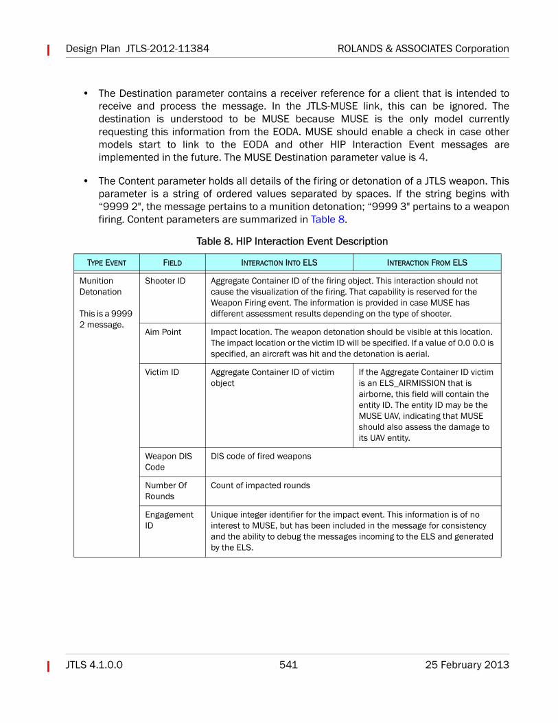
• The Content parameter holds all details of the firing or detonation of a JTLS weapon. Thisparameter is a string of ordered values separated by spaces. If the string begins with“9999 2", the message pertains to a munition detonation; “9999 3" pertains to a weaponfiring. Content parameters are summarized in Table 8.
Table 8. HIP Interaction Event Description
TYPE EVENT FIELD INTERACTION INTO ELS INTERACTION FROM ELS
Munition Detonation
This is a 9999 2 message.
Shooter ID Aggregate Container ID of the firing object. This interaction should not cause the visualization of the firing. That capability is reserved for the Weapon Firing event. The information is provided in case MUSE has different assessment results depending on the type of shooter.
Aim Point Impact location. The weapon detonation should be visible at this location. The impact location or the victim ID will be specified. If a value of 0.0 0.0 is specified, an aircraft was hit and the detonation is aerial.
Victim ID Aggregate Container ID of victim object
If the Aggregate Container ID victim is an ELS_AIRMISSION that is airborne, this field will contain the entity ID. The entity ID may be the MUSE UAV, indicating that MUSE should also assess the damage to its UAV entity.
Weapon DIS Code
DIS code of fired weapons
Number Of Rounds
Count of impacted rounds
Engagement ID
Unique integer identifier for the impact event. This information is of no interest to MUSE, but has been included in the message for consistency and the ability to debug the messages incoming to the ELS and generated by the ELS.
ROLANDS & ASSOCIATES Corporation Design Plan JTLS-2012-11384
25 February 2013 542 JTLS 4.1.0.0
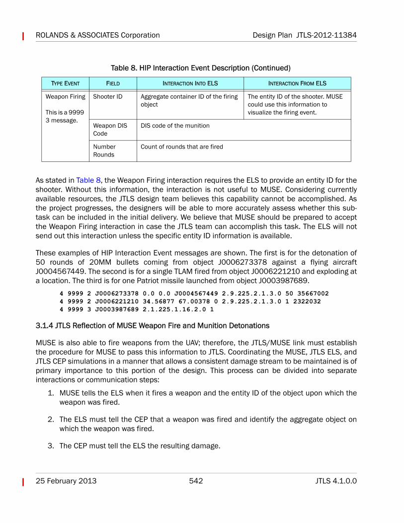
As stated in Table 8, the Weapon Firing interaction requires the ELS to provide an entity ID for theshooter. Without this information, the interaction is not useful to MUSE. Considering currentlyavailable resources, the JTLS design team believes this capability cannot be accomplished. Asthe project progresses, the designers will be able to more accurately assess whether this sub-task can be included in the initial delivery. We believe that MUSE should be prepared to acceptthe Weapon Firing interaction in case the JTLS team can accomplish this task. The ELS will notsend out this interaction unless the specific entity ID information is available.
These examples of HIP Interaction Event messages are shown. The first is for the detonation of50 rounds of 20MM bullets coming from object J0006273378 against a flying aircraftJ0004567449. The second is for a single TLAM fired from object J0006221210 and exploding ata location. The third is for one Patriot missile launched from object J0003987689.
4 9999 2 J0006273378 0.0 0.0 J0004567449 2.9.225.2.1.3.0 50 35667002 4 9999 2 J0006221210 34.56877 67.00378 0 2.9.225.2.1.3.0 1 2322032 4 9999 3 J0003987689 2.1.225.1.16.2.0 1
3.1.4 JTLS Reflection of MUSE Weapon Fire and Munition Detonations
MUSE is also able to fire weapons from the UAV; therefore, the JTLS/MUSE link must establishthe procedure for MUSE to pass this information to JTLS. Coordinating the MUSE, JTLS ELS, andJTLS CEP simulations in a manner that allows a consistent damage stream to be maintained is ofprimary importance to this portion of the design. This process can be divided into separateinteractions or communication steps:
1. MUSE tells the ELS when it fires a weapon and the entity ID of the object upon which theweapon was fired.
2. The ELS must tell the CEP that a weapon was fired and identify the aggregate object onwhich the weapon was fired.
3. The CEP must tell the ELS the resulting damage.
Weapon Firing
This is a 9999 3 message.
Shooter ID Aggregate container ID of the firing object
The entity ID of the shooter. MUSE could use this information to visualize the firing event.
Weapon DIS Code
DIS code of the munition
Number Rounds
Count of rounds that are fired
Table 8. HIP Interaction Event Description (Continued)
TYPE EVENT FIELD INTERACTION INTO ELS INTERACTION FROM ELS
Design Plan JTLS-2012-11384 ROLANDS & ASSOCIATES Corporation
JTLS 4.1.0.0 543 25 February 2013
4. The ELS must tell MUSE the new damage state of the object.
As an aggregate unit model, the JTLS CEP has no knowledge of entity IDs as used by the JTLS ELSand MUSE. However, when MUSE fires a weapon on a tank with an ID of M23112 and the CEPdetermines a kill, the ELS must ensure that the Tank M23112 damage flag is set to DESTROYED.This section describes how the entity is effectively identified when the ELS sets the damage flag.
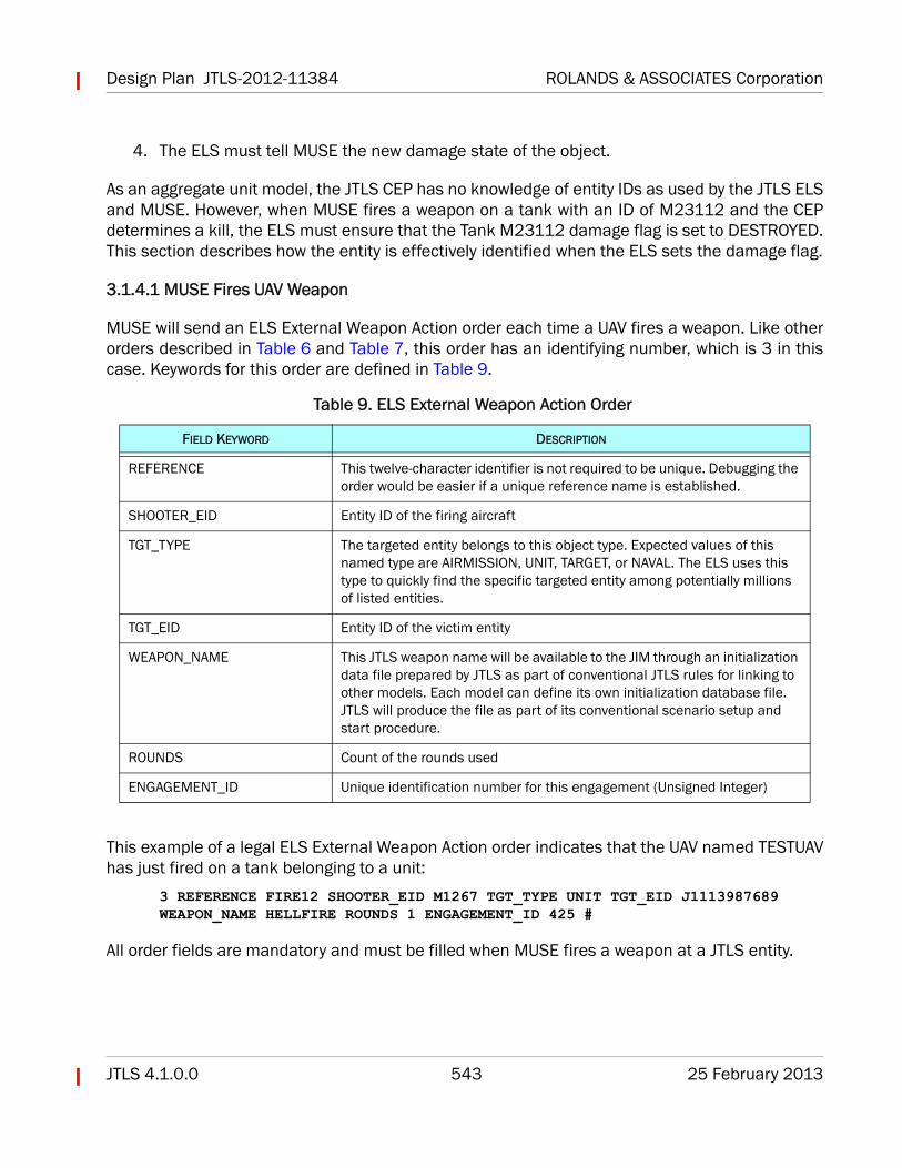
3.1.4.1 MUSE Fires UAV Weapon
MUSE will send an ELS External Weapon Action order each time a UAV fires a weapon. Like otherorders described in Table 6 and Table 7, this order has an identifying number, which is 3 in thiscase. Keywords for this order are defined in Table 9.
This example of a legal ELS External Weapon Action order indicates that the UAV named TESTUAVhas just fired on a tank belonging to a unit:
3 REFERENCE FIRE12 SHOOTER_EID M1267 TGT_TYPE UNIT TGT_EID J1113987689 WEAPON_NAME HELLFIRE ROUNDS 1 ENGAGEMENT_ID 425 #
All order fields are mandatory and must be filled when MUSE fires a weapon at a JTLS entity.
Table 9. ELS External Weapon Action Order
FIELD KEYWORD DESCRIPTION
REFERENCE This twelve-character identifier is not required to be unique. Debugging the order would be easier if a unique reference name is established.
SHOOTER_EID Entity ID of the firing aircraft
TGT_TYPE The targeted entity belongs to this object type. Expected values of this named type are AIRMISSION, UNIT, TARGET, or NAVAL. The ELS uses this type to quickly find the specific targeted entity among potentially millions of listed entities.
TGT_EID Entity ID of the victim entity
WEAPON_NAME This JTLS weapon name will be available to the JIM through an initialization data file prepared by JTLS as part of conventional JTLS rules for linking to other models. Each model can define its own initialization database file. JTLS will produce the file as part of its conventional scenario setup and start procedure.
ROUNDS Count of the rounds used
ENGAGEMENT_ID Unique identification number for this engagement (Unsigned Integer)
ROLANDS & ASSOCIATES Corporation Design Plan JTLS-2012-11384
25 February 2013 544 JTLS 4.1.0.0
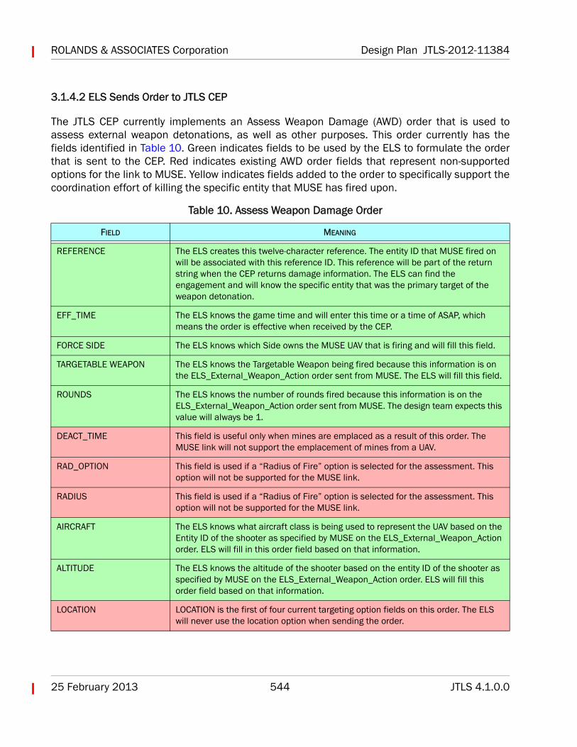
3.1.4.2 ELS Sends Order to JTLS CEP
The JTLS CEP currently implements an Assess Weapon Damage (AWD) order that is used toassess external weapon detonations, as well as other purposes. This order currently has thefields identified in Table 10. Green indicates fields to be used by the ELS to formulate the orderthat is sent to the CEP. Red indicates existing AWD order fields that represent non-supportedoptions for the link to MUSE. Yellow indicates fields added to the order to specifically support thecoordination effort of killing the specific entity that MUSE has fired upon.
Table 10. Assess Weapon Damage Order
FIELD MEANING
REFERENCE The ELS creates this twelve-character reference. The entity ID that MUSE fired on will be associated with this reference ID. This reference will be part of the return string when the CEP returns damage information. The ELS can find the engagement and will know the specific entity that was the primary target of the weapon detonation.
EFF_TIME The ELS knows the game time and will enter this time or a time of ASAP, which means the order is effective when received by the CEP.
FORCE SIDE The ELS knows which Side owns the MUSE UAV that is firing and will fill this field.
TARGETABLE WEAPON The ELS knows the Targetable Weapon being fired because this information is on the ELS_External_Weapon_Action order sent from MUSE. The ELS will fill this field.
ROUNDS The ELS knows the number of rounds fired because this information is on the ELS_External_Weapon_Action order sent from MUSE. The design team expects this value will always be 1.
DEACT_TIME This field is useful only when mines are emplaced as a result of this order. The MUSE link will not support the emplacement of mines from a UAV.
RAD_OPTION This field is used if a “Radius of Fire” option is selected for the assessment. This option will not be supported for the MUSE link.
RADIUS This field is used if a “Radius of Fire” option is selected for the assessment. This option will not be supported for the MUSE link.
AIRCRAFT The ELS knows what aircraft class is being used to represent the UAV based on the Entity ID of the shooter as specified by MUSE on the ELS_External_Weapon_Action order. ELS will fill in this order field based on that information.
ALTITUDE The ELS knows the altitude of the shooter based on the entity ID of the shooter as specified by MUSE on the ELS_External_Weapon_Action order. ELS will fill this order field based on that information.
LOCATION LOCATION is the first of four current targeting option fields on this order. The ELS will never use the location option when sending the order.
Design Plan JTLS-2012-11384 ROLANDS & ASSOCIATES Corporation
JTLS 4.1.0.0 545 25 February 2013
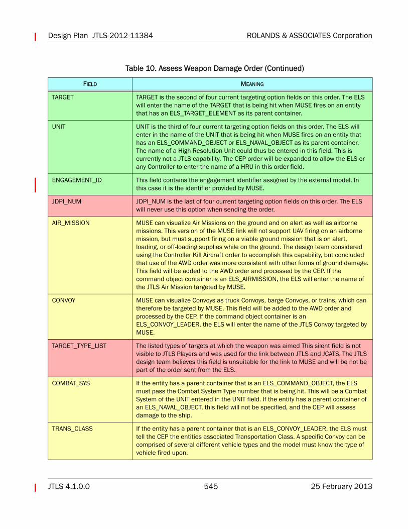
TARGET TARGET is the second of four current targeting option fields on this order. The ELS will enter the name of the TARGET that is being hit when MUSE fires on an entity that has an ELS_TARGET_ELEMENT as its parent container.
UNIT UNIT is the third of four current targeting option fields on this order. The ELS will enter in the name of the UNIT that is being hit when MUSE fires on an entity that has an ELS_COMMAND_OBJECT or ELS_NAVAL_OBJECT as its parent container. The name of a High Resolution Unit could thus be entered in this field. This is currently not a JTLS capability. The CEP order will be expanded to allow the ELS or any Controller to enter the name of a HRU in this order field.
ENGAGEMENT_ID This field contains the engagement identifier assigned by the external model. In this case it is the identifier provided by MUSE.
JDPI_NUM JDPI_NUM is the last of four current targeting option fields on this order. The ELS will never use this option when sending the order.
AIR_MISSION MUSE can visualize Air Missions on the ground and on alert as well as airborne missions. This version of the MUSE link will not support UAV firing on an airborne mission, but must support firing on a viable ground mission that is on alert, loading, or off-loading supplies while on the ground. The design team considered using the Controller Kill Aircraft order to accomplish this capability, but concluded that use of the AWD order was more consistent with other forms of ground damage.This field will be added to the AWD order and processed by the CEP. If the command object container is an ELS_AIRMISSION, the ELS will enter the name of the JTLS Air Mission targeted by MUSE.
CONVOY MUSE can visualize Convoys as truck Convoys, barge Convoys, or trains, which can therefore be targeted by MUSE. This field will be added to the AWD order and processed by the CEP. If the command object container is an ELS_CONVOY_LEADER, the ELS will enter the name of the JTLS Convoy targeted by MUSE.
TARGET_TYPE_LIST The listed types of targets at which the weapon was aimed This silent field is not visible to JTLS Players and was used for the link between JTLS and JCATS. The JTLS design team believes this field is unsuitable for the link to MUSE and will be not be part of the order sent from the ELS.
COMBAT_SYS If the entity has a parent container that is an ELS_COMMAND_OBJECT, the ELS must pass the Combat System Type number that is being hit. This will be a Combat System of the UNIT entered in the UNIT field. If the entity has a parent container of an ELS_NAVAL_OBJECT, this field will not be specified, and the CEP will assess damage to the ship.
TRANS_CLASS If the entity has a parent container that is an ELS_CONVOY_LEADER, the ELS must tell the CEP the entities associated Transportation Class. A specific Convoy can be comprised of several different vehicle types and the model must know the type of vehicle fired upon.
Table 10. Assess Weapon Damage Order (Continued)
FIELD MEANING
ROLANDS & ASSOCIATES Corporation Design Plan JTLS-2012-11384
25 February 2013 546 JTLS 4.1.0.0
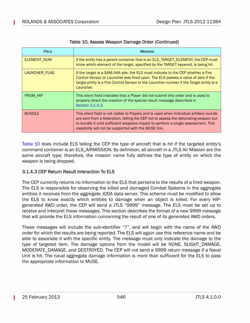
Table 10 does include ELS telling the CEP the type of aircraft that is hit if the targeted entity’scommand container is an ELS_AIRMISSION. By definition, all aircraft in a JTLS Air Mission are thesame aircraft type; therefore, the mission name fully defines the type of entity on which theweapon is being dropped.
3.1.4.3 CEP Return Result Interaction To ELS
The CEP currently returns no information to the ELS that pertains to the results of a fired weapon.The ELS is responsible for observing the killed and damaged Combat Systems in the aggregateentities it receives from the aggregate JODA data server. This scheme must be modified to allowthe ELS to know exactly which entities to damage when an object is killed. For every HIP-generated AWD order, the CEP will send a JTLS “9999” message. The ELS must be set up toreceive and interpret these messages. This section describes the format of a new 9999 messagethat will provide the ELS information concerning the result of one of its generated AWD orders.
These messages will include the sub-identifier “7”, and will begin with the name of the AWDorder for which the results are being reported. The ELS will again use this reference name and beable to associate it with the specific entity. The message must only indicate the damage to thetype of targeted item. The damage options from the model will be NONE, SLIGHT_DAMAGE,MODERATE_DAMAGE, and DESTROYED. The CEP will not send a 9999 return message if a NavalUnit is hit. The naval aggregate damage information is more than sufficient for the ELS to passthe appropriate information to MUSE.
ELEMENT_NUM If the entity has a parent container that is an ELS_TARGET_ELEMENT, the CEP must know which element of the target, specified by the TARGET keyword, is being hit.
LAUNCHER_FLAG If the target is a SAM/AAA site, the ELS must indicate to the CEP whether a Fire Control Sensor or Launcher was fired upon. The ELS passes a value of zero if the target entity is a Fire Control Sensor or the Launcher number if the Target entity is a Launcher.
FROM_HIP This silent field indicates that a Player did not submit this order and is used to properly direct the creation of the special result message described in Section 3.1.4.3.
BUNDLE This silent field is not visible to Players and is used when individual artillery rounds are sent from a federation, telling the CEP not to assess the detonating weapon but to bundle it until sufficient weapons impact to perform a single assessment. This capability will not be supported with the MUSE link.
Table 10. Assess Weapon Damage Order (Continued)
FIELD MEANING
Design Plan JTLS-2012-11384 ROLANDS & ASSOCIATES Corporation
JTLS 4.1.0.0 547 25 February 2013
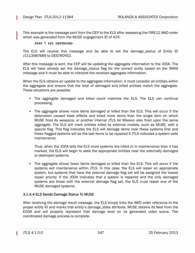
This example is the message sent from the CEP to the ELS after assessing the FIRE12 AWD orderwhich was generated from the MUSE engagement ID of 425:
9999 7 425 DESTROYED
The ELS will receive this message and be able to set the damage_status of Entity IDJ1113987689 to DESTROYED.
After this message is sent, the CEP will be updating the aggregate information to the JODA. TheELS will have already set the damage_status flag for the correct entity based on the 9999message and it must be able to interpret the received aggregate information.
When the ELS obtains an update to the aggregate information, it must consider all entities withinthe aggregate and ensure that the total of damaged and killed entities match the aggregate.These situations are possible:
• The aggregate damaged and killed count matches the ELS. The ELS can continueprocessing.
• The aggregate shows more items damaged or killed than the ELS. This will occur if thedetonation caused blast effects and killed more items than the single item on whichMUSE fired its weapons, or another internal JTLS Air Mission also fired upon the sameaggregate. The ELS will mark entities killed by external models, such as MUSE, with aspecial flag. This flag indicates the ELS will damage items near these systems first andthese flagged systems will be the last items to be repaired if JTLS indicates a system exitsmaintenance.
Thus, when the JODA tells the ELS more systems are killed or in maintenance than it hasmarked, the ELS will begin to seek the appropriate entities near the externally damagedor destroyed systems.
• The aggregate shows fewer items damaged or killed than the ELS. This will occur if thesystems exit maintenance within JTLS. In this case, the ELS will repair an appropriatesystem, but systems that have the external damage flag set will be assigned the lowestrepair priority. If the JODA indicates that a system is repaired and the only damagedsystems are those with the external damage flag set, the ELS must repair one of theMUSE damaged systems.
3.1.4.4 ELS Sends Damage Status To MUSE
After receiving the damage result message, the ELS simply links the AWD order reference to theproper entity ID and marks that entity’s damage_state attribute. MUSE obtains its feed from theEODA and will properly represent that damage level on its generated video scene. Thecoordinated damage process is complete.
ROLANDS & ASSOCIATES Corporation Design Plan JTLS-2012-11384
25 February 2013 548 JTLS 4.1.0.0
3.2 JTLS Scenario Setup For a Linked Game
The JTLS scenario will be prepared as any scenario is prepared for a typical JTLS exercise and willnot require special MUSE data to link. These DDS options will be required:
• One or more UAV Squadrons will be configured as externally owned by MUSE. When theSquadrons are specified as owned by MUSE, a JTLS Player will be unable to use theseassets as part of their normal orders. These UAVs may be in the ATO and must beassigned specific numbers, including specific MODE 1, MODE 2, and MODE 3Identification Friend or Foe (IFF) Squawk values. MUSE will be responsible to assign thesevalues. Alternatively, the JTLS Change Mission Parameter order can be used to set thisinformation, which will eventually be displayed on any real-world C4I systems.
• DIS codes must applied for all types of Combat Systems. Existing structures can hold andtransmit these data to MUSE, including dynamic DIS codes, such as those used to displaytargets in various states of readiness.
The JIM client will require only a small scenario initialization data file. This file will contain thenames of all weapons used in the scenario and must be mapped to corresponding weaponsused by MUSE. All other data needed by the client can be discovered from the EODA when theJIM client first connects. Consider the case that MUSE owns some aircraft at a Squadron. Allaircraft available to MUSE and their corresponding states of readiness will be discovered fromthe EODA. Thus, the JIM client can discover the number of aircraft it has available for its ownmissions. From the initialization data, the JIM client will know which weapons can be fired fromits aircraft.
3.3 Initialization Data
An initialization data file must be provided by JTLS in order for MUSE to fully display all of the JTLSsystems. A new report will be generated from the DDS which lists all of the non-zero DIS Codes inthe JTLS database. If JTLS publishes an object using a DIS code of all zeros ("0.0.0.0.0.0"), thenit is not meant to be displayed within MUSE. All other objects should have valid DIS Codes andMUSE must identify the proper model to use for display purposes.
This report will be generated using the new DDS Report capability described in JTLS-0108 SUPDDS Report.
MUSE must inform the JTLS design team whether JTLS should be responsible for assigning these real-world database parameters that are needed to properly identify the UAVs on real-world C4I systems.
Design Plan JTLS-2012-11384 ROLANDS & ASSOCIATES Corporation
JTLS 4.1.0.0 549 25 February 2013
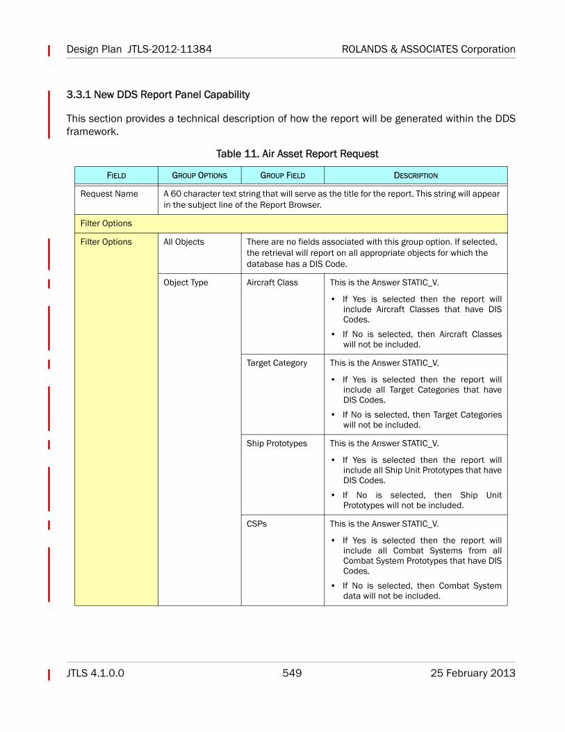
3.3.1 New DDS Report Panel Capability
This section provides a technical description of how the report will be generated within the DDSframework.
Table 11. Air Asset Report Request
FIELD GROUP OPTIONS GROUP FIELD DESCRIPTION
Request Name A 60 character text string that will serve as the title for the report. This string will appear in the subject line of the Report Browser.
Filter Options
Filter Options All Objects There are no fields associated with this group option. If selected, the retrieval will report on all appropriate objects for which the database has a DIS Code.
Object Type Aircraft Class This is the Answer STATIC_V.
• If Yes is selected then the report willinclude Aircraft Classes that have DISCodes.
• If No is selected, then Aircraft Classeswill not be included.
Target Category This is the Answer STATIC_V.
• If Yes is selected then the report willinclude all Target Categories that haveDIS Codes.
• If No is selected, then Target Categorieswill not be included.
Ship Prototypes This is the Answer STATIC_V.
• If Yes is selected then the report willinclude all Ship Unit Prototypes that haveDIS Codes.
• If No is selected, then Ship UnitPrototypes will not be included.
CSPs This is the Answer STATIC_V.
• If Yes is selected then the report willinclude all Combat Systems from allCombat System Prototypes that have DISCodes.
• If No is selected, then Combat Systemdata will not be included.
ROLANDS & ASSOCIATES Corporation Design Plan JTLS-2012-11384
25 February 2013 550 JTLS 4.1.0.0
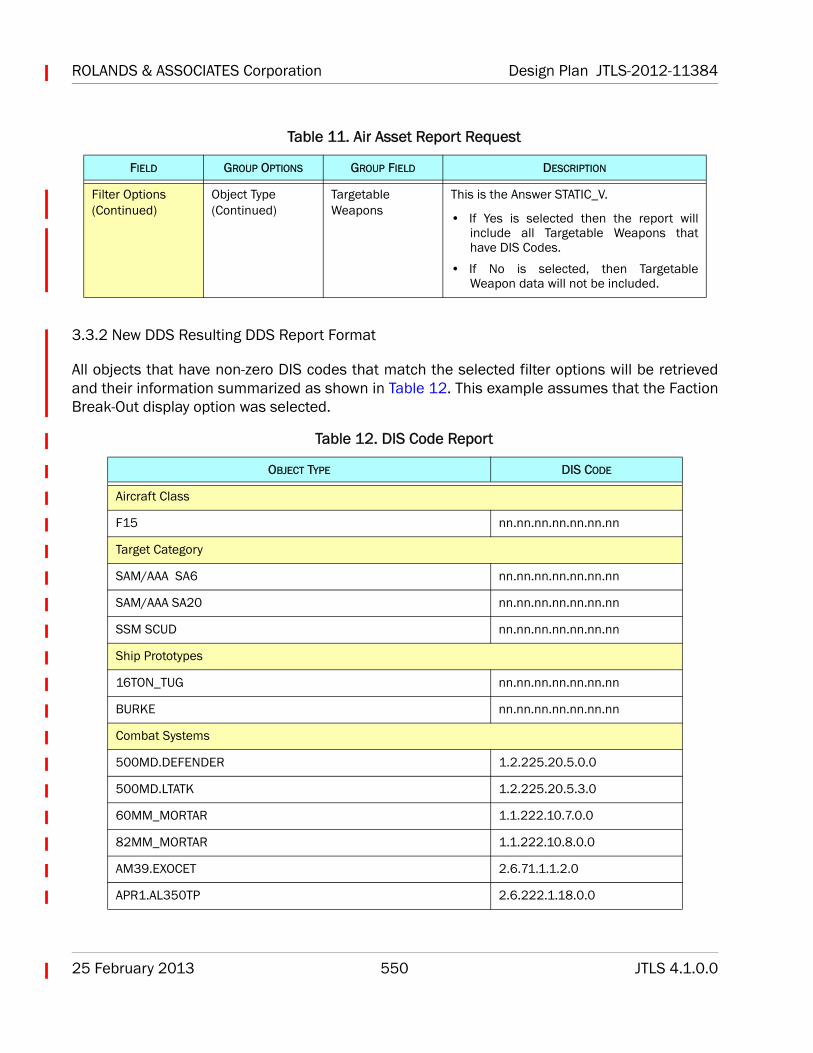
3.3.2 New DDS Resulting DDS Report Format
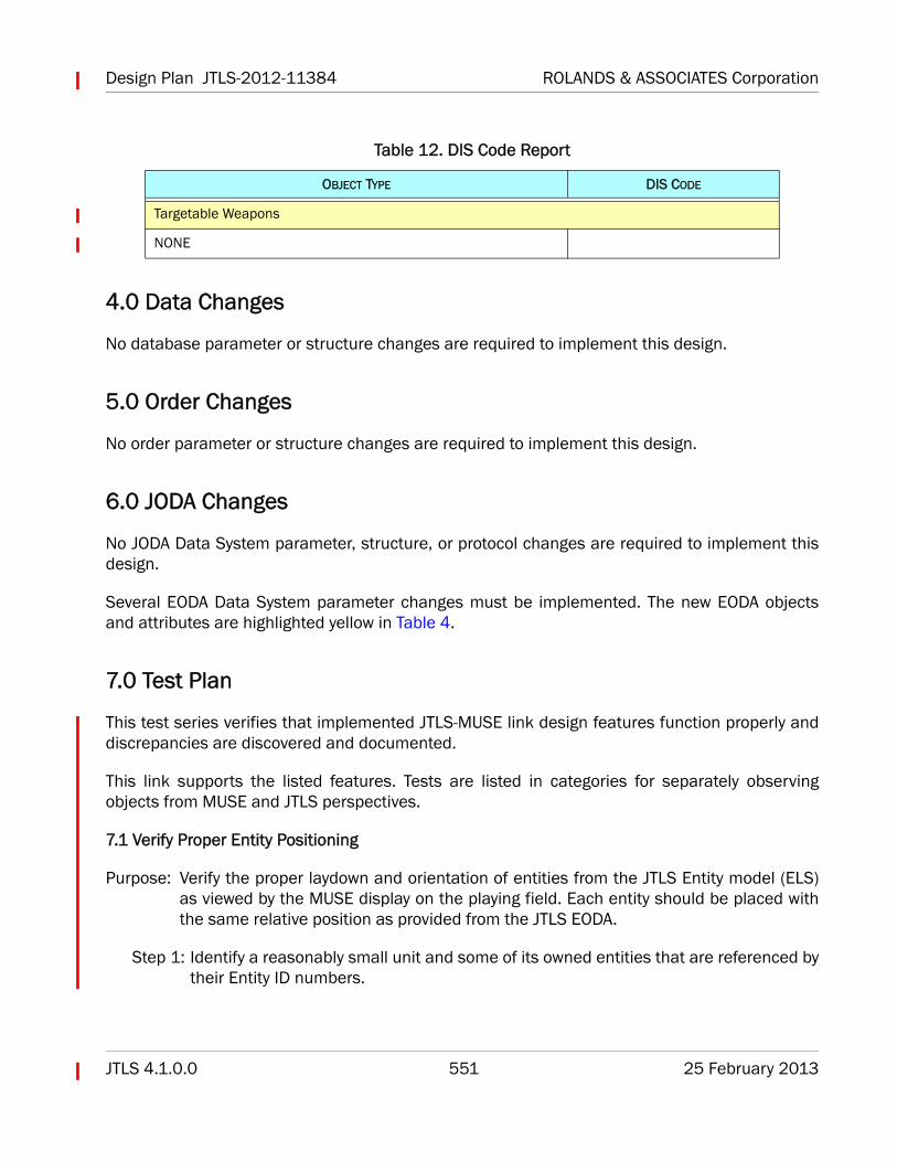
All objects that have non-zero DIS codes that match the selected filter options will be retrievedand their information summarized as shown in Table 12. This example assumes that the FactionBreak-Out display option was selected.
Filter Options (Continued)
Object Type (Continued)
Targetable Weapons
This is the Answer STATIC_V.
• If Yes is selected then the report willinclude all Targetable Weapons thathave DIS Codes.
• If No is selected, then TargetableWeapon data will not be included.
Table 12. DIS Code Report
OBJECT TYPE DIS CODE
Aircraft Class
F15 nn.nn.nn.nn.nn.nn.nn
Target Category
SAM/AAA SA6 nn.nn.nn.nn.nn.nn.nn
SAM/AAA SA20 nn.nn.nn.nn.nn.nn.nn
SSM SCUD nn.nn.nn.nn.nn.nn.nn
Ship Prototypes
16TON_TUG nn.nn.nn.nn.nn.nn.nn
BURKE nn.nn.nn.nn.nn.nn.nn
Combat Systems
500MD.DEFENDER 1.2.225.20.5.0.0
500MD.LTATK 1.2.225.20.5.3.0
60MM_MORTAR 1.1.222.10.7.0.0
82MM_MORTAR 1.1.222.10.8.0.0
AM39.EXOCET 2.6.71.1.1.2.0
APR1.AL350TP 2.6.222.1.18.0.0
Table 11. Air Asset Report Request
FIELD GROUP OPTIONS GROUP FIELD DESCRIPTION
Design Plan JTLS-2012-11384 ROLANDS & ASSOCIATES Corporation
JTLS 4.1.0.0 551 25 February 2013
4.0 Data Changes
No database parameter or structure changes are required to implement this design.
5.0 Order Changes
No order parameter or structure changes are required to implement this design.
6.0 JODA Changes
No JODA Data System parameter, structure, or protocol changes are required to implement thisdesign.
Several EODA Data System parameter changes must be implemented. The new EODA objectsand attributes are highlighted yellow in Table 4.
7.0 Test Plan
This test series verifies that implemented JTLS-MUSE link design features function properly anddiscrepancies are discovered and documented.
This link supports the listed features. Tests are listed in categories for separately observingobjects from MUSE and JTLS perspectives.
7.1 Verify Proper Entity Positioning
Purpose: Verify the proper laydown and orientation of entities from the JTLS Entity model (ELS)as viewed by the MUSE display on the playing field. Each entity should be placed withthe same relative position as provided from the JTLS EODA.
Step 1: Identify a reasonably small unit and some of its owned entities that are referenced bytheir Entity ID numbers.
Targetable Weapons
NONE
Table 12. DIS Code Report
OBJECT TYPE DIS CODE
ROLANDS & ASSOCIATES Corporation Design Plan JTLS-2012-11384
25 February 2013 552 JTLS 4.1.0.0
Step 2: Use the EODA to find the data record for the object and record the location of theowning command objects.
Step 3: Find each of the entities owned by the command object and record their X and Yoffsets from the location of the command object.
Step 4: Plot each entity on paper and compare this plot to the unit lay-down observed in theMETAVR display for the same unit.
Expected Results: Entities should be located at their corresponding offset locations andindicate the specified facing direction. These special cases are excepted:
• Ship or submarine-mounted entities are not displayed.
• Some personnel may be mounted and not displayed.
• All trucks are displayed, even when destroyed.
• Many Convoy trucks will be dispatched from disaggregated and aggregated units. Trucksfrom aggregated units will be deleted when the Convoy completes. Aircraft and aircraft inAir Missions will behave similarly.
• Dead or immobilized entities are left behind on the ground.
7.2 Verify Entity Damage State
Purpose: Demonstrate that MUSE can display images for damaged entities for all of the JTLSentities. The JTLS model will provide entities of several object types and for eachdamage state (None, Slight, Moderate and Destroyed) and MUSE will properly displayeach with corresponding damage effects.
Step 1: Locate several types of units in JTLS and Magic Move each unit to a remote locationof the game board to isolate them in the MUSE viewer.
Step 2: Use the Controller WHIP to damage the units and observe the entities in the MUSEMETAVR display. Use None, Slight, Moderate, or Destroyed to describe ground units.Refer to JTLS damage states for ship objects.
Design Plan JTLS-2012-11384 ROLANDS & ASSOCIATES Corporation
JTLS 4.1.0.0 553 25 February 2013
Expected Results: Entity objects should appear in MUSE and indicate damage that matchesinformation provided from JTLS for each object.
7.3 Verify Entity Movement
Purpose: Verify that for various moving objects the associated entities move accordingly. Entitiesassociated with a moving object in JTLS are displayed in MUSE and movingappropriately.
Step 1: Use a Player WHIP to select a unit to move. The unit must be disaggregated to bedisplayable in MUSE.
Step 2: Issue a Move order from the WHIP.
Step 3: Use a Player WHIP to select a Squadron to launch an Air Mission. The Squadron mustbe disaggregated.
Step 4: Issue an order to fly a mission. Note the aircraft type and entity number. The entitynumber can be obtained from the EODA by searching the mission name. Use this tolocate the aircraft entity in the MUSE METAVR viewer.
Expected Results:
• Aircraft move at their specified altitude. Ensure they are not following terrain.
• Personnel and other systems of a moving unit maintain their relative positions.
• Trucks form a line when part of a Convoy and moving.
• Ensure that rubber-banding caused by dead-reconning does not occur.
• Ensure that jumping caused by aggregate model update does not occur.
7.4 Verify Weapon Fire
Purpose: The purpose of this test is to verify that weapon detonations generated in JTLS arereceived in
7.5 Verify Munition Detonation
Purpose: Demonstrate a visual blast effect in MUSE for weapons impacting in JTLS.
Step 1: Use the Controller WHIP and the Assess Weapon Damage order send a volley ofseveral rounds of high explosives at a location that is currently viewed in the MUSEdisplay.
ROLANDS & ASSOCIATES Corporation Design Plan JTLS-2012-11384
25 February 2013 554 JTLS 4.1.0.0
Step 2: Locate a ship in MUSE that is published by JTLS. Send a perception Side WHIP orderto fire precision weapons at the ship. Observe the impact(s).
Step 3: Launch a UAV mission from MUSE. Launch a CAP mission in JTLS to intercept andshadow the UAV. Launch a foreign side CAP mission with ROE to fire on the firstmission. Manual pair the mission to the first CAP and observe the munitionsimpacting.
Expected Results: In each case, weapon impacts will be observed from the MUSE viewer.
7.6 Verify Reflection of MUSE UAV Air Missions
Purpose: Ensure that MUSE UAV missions are reflected in JTLS with proper mission loads andnumber and type of aircraft.
Step 1: Properly map the aircraft type between those intended to be flown by MUSE andthose of the Squadron(s) identified in JTLS as owned by MUSE.
Step 2: Launch UAVs, observe them in JTLS, and compare them to the MUSE missions.
Expected Results:
• JTLS can reflect multiple missions.
• JTLS properly reflects damaged aircraft.
• JTLS has an accurate load of sensors, weapons, jammers, and fuel.
• JTLS does not allow missions when the squadron's aircraft are unavailable.
• JTLS collects intel for the UAV mission as MUSE navigates the mission over the gameboard.
7.7 Verify Munition Detonation
Purpose:
7.8 Verify JTLS Initialization Data File
Purpose: Ensure the JIM client can parse a data file <scenario>.mus for JTLS weapons name toDIS code mapping (not implemented).
Step 1: Generate an initialization data file from JTLS.
Step 2: Provide the data file to MUSE personnel.
Design Plan JTLS-2012-11384 ROLANDS & ASSOCIATES Corporation
JTLS 4.1.0.0 555 25 February 2013
Step 3: Parse the data and compare several names and DIS codes.
Expected Results: The JIM client is capable of retrieving a full set of weapon names for theweapon DIS codes used in any JTLS scenario.
7.9 Verify Timely Receipt of Data
Purpose: Verify that the JIM client can receive and send EODA data objects and orders andmessages without delay. The JIM client and all MUSE applications must not lag whileprocessing scenario data.
Step 1: After the CEP has completed data download and before setting game speed, connectthe JIM and start the timer.
Step 2: Stop the timer when the JIM finished providing all the data to the WES
Step 3: Record the time as the initial flood of objects from the EODA to the JIM.
Step 4: Complete update of initial objects to the WES
Step 5: Repeat Steps 1, 2, and 3. Start the timer when the download to the JIM completes.
Step 6: Stop the timer when the JIM has finished transmitting PDU's to the WES.
Step 7: Record the time as the initial flood of objects from the JIM to the WES.
Expected Results: The JIM should be able to receive and reformat the EODA data for displayto the MUSE viewer without a noticeable delay.

ROLANDS & ASSOCIATES Corporation Design Plan JTLS-2012-11384
25 February 2013 556 JTLS 4.1.0.0