Embed Size (px)
Citation preview
BJS/MS/3758.02/080104
PART 2
SPECIFICATION
OF CONSTRUCTION MATERIALS
AND
STANDARD CONSTRUCTION DETAILS
BJS/MS/3758.02/080104
PART 2
SPECIFICATION OF CONSTRUCTION MATERIALS AND STANDARD CONSTRUCTION DETAILS
INDEX
SECTIONS PAGE NUMBER
1. INTRODUCTION 2
2. MATERIALS 4
3. SITE PREPARATION AND GENERAL WORKS 11
4. EARTHWORKS 12
5. DRAINAGE 14
6. KERBS, FOOTWAYS AND PAVED AREAS 18
7. FLEXIBLE CARRIAGEWAYS 20
8. FOOTWAYS AND VEHICLE CROSSINGS 37
9. HIGHWAY VERGES AND PLANTING 39
10. STREET LIGHTING 41
11. COMPLETION OF WORKS 42
12. MISCELLANEOUS 43
13. STANDARD CONSTRUCTION DETAILS 44
BJS/MS/3758.02/080104
1. INTRODUCTION
THIS DOCUMENT IS TO BE READ IN CONJUNCTION WITH THE DESIGN GUIDE FOR RESIDENTIAL ROADS, THE HIGHWAYS AGENCY MANUAL OF CONTRACT DOCUMENTS FOR HIGHWAY WORKS AND THE SOUTH YORKSHIRE LABORATORY SPECIFICATION FOR THE SUPPLY OF MATERIALS FOR USE IN HIGHWAY WORKS INTRODUCTION This General Specification is issued for the guidance of developers, and forms the general basis for alternative methods of construction for Housing Estate Roads and Industrial Estate Roads which the Highway Authority is ultimately required to adopt as highway to be maintained at public expense. INSPECTIONS The Highway Authority shall be notified at least 3 days Notice prior to the commencement of any stage of the works.
If, as a result of failure to give adequate notice of any stage of the Failure to give construction works the Engineer is unable to inspect the same, the adequate notice Developer will be required to carry out tests at his own expense to prove to the Highway Authority’s satisfaction that the works comply with the appropriate standard. Otherwise, on completion, the work may not be considered for adoption.
The Highway Authority representative shall be given access to the Access for work in progress and may visit from time to time. Such visits do The Highway not absolve the Developer from his responsibility for supervising Authority the work that he is paying for, or from ensuring that it is carried representative out in accordance with the Specification and approved drawings. EXISTING SUB-GRADE All construction details shown in this document are based upon an Assumed CBR assumed CBR of 2%. If agreed in writing with the Engineer, Values thickness of sub-base and or capping layer may vary if a sub-grade survey indicates that there is an increase or decrease in CBR values.
When the sub-grade is frost susceptible, a minimum construction Frost thickness of 450mm will be required. susceptible
sub-grade DEFINITIONS Unless otherwise stated, the definition of terms used in this General Specification shall be that in the Glossary of Highway Engineering Terms and BS 6100: 2.4.1
The Engineer, for the purposes of this Specification, shall be the The Engineer representative of The Highway Authority.
Where reference is made in this document to the Contractor, this The Contractor shall mean the Developer or Party entering into agreement with the Highway Authority in respect of the adoption of the highway.
British Standard - this term will be used where reference is made British to a British Standards Institution Specification and the edition Standard current at the time of construction is to be complied with. (See Section 2 – materials)

BJS/MS/3758.02/080104
ROAD TYPES These are detailed in the Design Guides for Residential and Industrial Roads, and are summarised below. 2. Industrial Estate Roads
3. Main Road
Parade 4. Collector Street
Local Street
5. Village Street
5B. Square/Mews Court Homezone
Footpath + Private Drive (Not adopted) Footpath Mode specific link
BJS/MS/3758.02/080104
2. MATERIALS Wherever, in respect of any British Standard (BS), a BSI Kitemark BS Certification scheme is available, all materials are required to comply Accreditation with that standard, or the containers of such materials, shall be marked with a BSI Certification Trademark (the Kitemark). The mark of conformity of any other third party certification body accreditation by the National Accreditation Council for Certification Bodies or equivalent shall be an acceptable alternative to this requirement. At the date of construction, all articles and materials shall conform to: - GENERAL
A) the above
B) The Highways Agency for Highway Works modified or extended by any substitute or additional clauses referred to in this document
C) The South Yorkshire Laboratory Specifications for the Supply
of Materials for use in Highway Works And the following:- SAMPLES AND TESTING Representative samples of all materials proposed to be used in the General works shall be submitted for the Engineer’s approval not less than three weeks before they are to be used in the works, and shall be in accordance with South Yorkshire Laboratory Specification for the Supply of Materials for use in Highway Works. Such approval shall be obtained before any materials are delivered to site. Any materials not conforming with the Specification and requirements will be condemned in which case they must be removed from the site. The Engineer may require material to be tested on a routine Routine basis at a rate which will normally not exceed; Testing
Carriageway One sample per 50m length of carriageway. (Sub base and road base Material)
One sample per 100m length of carriageway. (Surfacing Material) It may be necessary to take samples for each laying operation Footways If any material is below the quality required, it will be condemned and must be removed. The Developer shall bear the cost of all sampling and testing Costs required by the Engineer. These costs are normally included in the Section 38 agreement and Advance Payments Code Section 220 of The Highways Act 1980. However, the Engineer may require extra tests and these shall be paid for by the Developer.
Porous pipes shall comply with the requirements of South Yorkshire Porous Laboratory Specification No. 13.(Concrete porous pipes). Pipes
Vitrified clay pipes shall comply with BS EN 295 and BS 65. Vitrified
BJS/MS/3758.02/080104
The fittings shall have flexible mechanical joints. They shall be Clay pipes bedded on material complying with South Yorkshire Laboratory Specification No. 26 and in accordance with “Simplified tables of External Loads on Buried Pipelines”, issued by The Transport Research laboratory.
Plastic pipes fittings and joints shall be in accordance with the Plastic pipes requirements of BS 4660, BS EN 1401/1 and the water industry and fittings specification WIS 4/35/01.
Concrete Pipes and fittings shall comply with the requirements of Concrete BS 5911 : Part 100 and South Yorkshire Laboratory Specification Pipes and
No. 14. Fittings
Unless otherwise agreed in writing with The Engineer, all pipes Joints & shall be:- bedding
Flexibly jointed. Bedded on material conforming with South Yorkshire Laboratory Specification No. 26 and designed in accordance with “Simplified Tables of External Loads on Buried Pipelines”, issued by the Transport Research Laboratory. Bricks are to be a Class B Engineering or Concrete Engineering Bricks for quality complying to South Yorkshire Laboratory Specification manholes,gullies Number 16, and are to be laid in English bond. and Soak-aways etc DRAINAGE IRONWORK Drainage ironwork shall comply in all respects with BS EN 124 BS and be Kitemarked or equivalent (any certification body accredited to BS EN 45011). Products shall be manufactured by companies who operate to Quality BS EN ISO 9000 Series Quality System Standards. assurance Ductile iron Class D400 (150mm deep) double triangular to Manhole BS EN 124 with 600mm square openings as manufactured by: covers and frames Stanton (Inter-Ax D400-H) (Or similar approved). Must be ductile iron with captive hinge to BS EN 124. Gully grates and frames Minimum Class D400 Industrial Estate and Type As manufactured by: 3 Roads Stanton Watershed D400 HR 865 1 (Or similar approved) Minimum Class C250 (100mm deep) All other road types As manufactured by: Stanton HY 813 (Or similar approved) To be in accordance with BS 1247. Step irons for Manholes
BJS/MS/3758.02/080104
GULLY POTS
For typical gully details, See STANDARD CONSTRUCTION DETAILS General All gullies shall be trapped and provided with a rodding eye and fixed chain stopper. Shall comply with the current British Board of Agrément Roads and Plastic Bridges Certificate (BBA Publications). Shall comply with the requirements of BS 5911 : Part 230 Precast concrete “Precast Concrete Pipes, Fittings and Ancillary Products” and South Yorkshire Laboratory Specification No. 14. Shall comply with the requirements for road gullies, as specified Clay in BS 65 “Specifications for vitrified clay pipes, fittings and ducts” or BS EN 295, and shall be in accordance with South Yorkshire Laboratory Specification No. 12. Shall be clay trapped gully pots complying with BS.65 and/or Footway gullies BS EN 295 and South Yorkshire Laboratory Specification No 12 with galvanised bucket. The gullies are to be covered with a hinged grating and frame. (See STANDARD CONSTRUCTION DETAILS). CONCRETE All concrete shall be in accordance with BS 5328. BS All concrete used shall be made of aggregate, cement and water Constituent and shall comply with the conditions given below:- Parts Where standard mixes are specified, the related strengths shall be as Standard follows:- mixes
ST4 20.0 N/mm2 ST5 25.0 N/mm2 In all phases of the work involving concrete, the concrete must be Placing placed before the initial set has commenced. Before concreting works commence, trial mixes, using the Concrete aggregates proposed for the work shall be made to ensure that carriageways, the concrete is sufficiently workable and that no segregation Bus draw- ins, of the mix occurs during either transportation or placing. lay-bys, In-situ The composition of these trial mixes shall be adjusted to ensure channelling, that the characteristic compressive strength of cubes tested in Manhole slabs batches of four shall be 40N per mm2 at 28 days. The concrete shall be air-entrained and the total quantity of air as a percentage of the volume of the mix shall be 5% + 1.5%. Concrete for these purposes shall be of such proportions as to Concrete provide a characteristic compressive strength of 25N per mm2 Manhole (ST5)at 28 days. When required by the Engineer the Contractor foundations shall satisfy him that the arrangements for mixing the concrete are benching and adequate to produce a material of the right quality, and shall concrete rafts supply batches of four cubes for test purposes. Pipe bedding and haunching. Concrete grade Bedding and backing of kerbs and edging. ST4 (20N/mm2) Manhole surrounds. shall be used
BJS/MS/3758.02/080104
Gully bases and surrounds. for these Steel pedestrian fencing surround. purposes Pipe saddling. Trench bases. Blinding bases of excavations. MORTAR Ordinary Portland Cement shall be used unless otherwise specified. Cement Mortar To be mixed by volume at a ratio 1 of cement to 3 sand. Natural sand on crushed natural stone or combination of both as specified in BS1200 (Specifications for building sands from natural resources). CONCRETE KERBS CHANNEL AND EDGING All precast concrete kerbs, channels and edging shall be Concrete kerbs hydraulically pressed and shall comply with the requirements channel and of South Yorkshire Laboratory Specification No. 11. Special edging kerbs (Plasmobility) having dimensions complying with BS 7263, may be approved by The Engineer. ROAD PAVEMENTS
Sub-base shall be in accordance with South Yorkshire Laboratory Sub-base Specification No. 19. The source material shall be approved by The Engineer. Dense Base (Roadbase) to BS 4987 and South Yorkshire Base Laboratory Specification No. 30. (Roadbase)
Surfacing Dense Binder Course complying with BS 4987 and Binder course South Yorkshire Laboratory Specification No. 31. OR
Rolled Asphalt complying with BS 594 and South Yorkshire Laboratory Specification No.7.
Stone Mastic Asphalt complying with BS 4987 and to Surface South Yorkshire Laboratory Specification No. 41 Course
OR
Rolled Asphalt to complying with BS 594 and South Yorkshire Laboratory Specification No. 29
OR
10mm size Close Graded Surface Course complying with BS 4987 and South Yorkshire Laboratory Specification No. 33
OR
6mm size dense Surface Course to BS 4987 and South Yorkshire Laboratory Specification No. 34
OR
Interlocking Block Paving complying with BS 6717 “Precast concrete paving blocks”
Notes
Materials containing limestone or blast furnace slag aggregate Blast furnace shall NOT be permitted in the Surface Course. slag

BJS/MS/3758.02/080104
When the surfacing course is laid in stages the same Stage laying aggregate must be used for each stage.
BITUMINOUS BINDERS All binders in bituminous materials must be straight-run. Addition of fluxing agents is not permitted without written permission from The Engineer Joint sealing compound shall consist of either hot or cold poured Joint sealing material as detailed page 28 - JOINTS IN FLEXIBLE SURFACING Compound
BJS/MS/3758.02/080104
FOOTWAY PAVEMENTS
The material used shall consist of a compacted layer of Type 1 Sub Base for granular sub-base material and shall comply with the footways and requirements of the South Yorkshire Laboratory Specification No 19 margins Surfacing for footways 6mm size Surfacing Course to BS 4987 and complying with Asphalt South Yorkshire Laboratory Specification No. 34 With
20mm size Binder Course to BS 4987and complying with South Yorkshire Laboratory Specification No. 31
OR
Precast concrete flags shall comply with the requirements of PCC Flags South Yorkshire Laboratory Specification No. 11, be bedded on sharp sand and cement at a ratio of 6:1on the prepared sub-base
OR
Interlocking Block Paving (Pencil Edge) Block Paving
OR Natural stone flags Natural
Stone flags
The surfacing for non-vehicular hardened margins shall Surfacing for be 60mm thick concrete block paving bedded on 35mm non-vehicular compacted thickness of sharp sand hardened
margins
See STANDARD CONSTRUCTION DETAILS Cycle track construction ROAD HUMPS See STANDARD CONSTRUCTION DETAILS Construction
Position of road humps to be agreed with Highway Authority at planning stage. Locations Geometrical design shall be in accordance with the latest Regulations version of The Highways (Road Humps) Regulations.

BJS/MS/3758.02/080104
PAINT FOR METALWORK Shall be carried out in accordance with the methods recommended Paintwork in BS 6150, using materials complying with Clause 164 and primed at the works in accordance with BS 5493 Paintwork specification for handrails and safety barrier 1st coat - Galvanising - Hot dip galvanising minimum thickness of galvanising 70 micron B.S.729 2nd coat and preparation "T" wash (or similar) 3rd coat - Primer - Zinc phosphate metal primer 4th coat - Undercoat 1 - Alkyd undercoat (Grey) 5th coat - Undercoat 2 - Alkyd undercoat (White) 6th coat - Top Coat - Permaglaxe 12D45 - Green (or similar approved) NB 1st 2nd and 3rd coats to be carried out in factory
BJS/MS/3758.02/080104
3. SITE PREPARATION AND GENERAL WORKS
The investigation should gather all data needed for assessing: Ground Investigation
A General suitability of the site and neighbourhood for the
proposed development works
B Physical characteristics of the ground e.g. presence of In-ground obstacles, services, buried conduits, sumps soft spots, cellars etc.
C Physical characteristics of contaminated matrices e.g. mineralogy, moisture content, permeability, chemical composition, particle size distribution
D Geotechnical characteristics e.g. strength, compressibility, stability of slopes,existing structures, potential for subsidence etc.
E The need for design requirements of any foundations, earthworks, temporary works and specialist geotechnical processes associated with the development strategy, taking into account the effect of any previous uses of the site.
F Any factors arising from the soil or groundwater conditions that might constrain the construction or implementation of development works including temporary works, excavation, traffickability and drainage.
G The quantity, quality and ease of extraction of construction materials
(e.g. concrete foundations) suitable for inclusion in the works
H Changes in the stability, drainage or other geotechnical aspects of the site and the surrounding ground and buildings which might be initiated by the development works.
In addition, it may be necessary to assess the stability of existing structures, or to evaluate potential failure or instability. All investigation works shall be carried out in accordance with BS 5930. Specialist geotechnical processes shall be specified and designed in accordance with appropriate industry standards or relevant Code of Practice. The lines and levels of the carriageways, footways, verges, drains and all other Setting out works shall be properly set out before commencement of the Works. The Contractor shall remove buildings to a minimum of 1.5m below formation Site clearance level) and other obstructions, grub up and remove trees, hedges, bushes, shrubs and clear the site of the works to the satisfaction of The Engineer.
Cellars to be excavated and filled to specification.
Drawings showing site clearance details together with appropriate Drawings schedules and appendices shall be submitted to The Engineer prior to commencement of the works The provision of a comprehensive system of sub-soil drainage may Sub-Soil be required where proposed roads are in cutting or where there is Drainage evidence that the general level of the water table is within 600mm of the carriageway formation level
BJS/MS/3758.02/080104
4. EARTHWORKS
All Earthworks are to carried out in accordance with the General latest requirements of Series 600 of The Highways Agency Specification For Highway Works:- The latest requirements of South Yorkshire Laboratory Specification For The Supply of Materials For Use in Highway Works:- And the following:- Drawings showing earthworks details together with Drawings appropriate schedules and appendices shall be submitted to The Engineer prior to commencement of the works. All topsoil shall be removed from the area required for Topsoil highway construction.
Excavation shall be to correct lines, levels and contours. Line & level Where rock is met in excavation it shall be cut out to the Excavation lines and levels shown on the approved drawings, or as in Rock directed by The Engineer. Surface irregularities present in the formation after completion of the rock excavation shall be corrected with a layer of mass concrete grade ST4 laid and compacted to the required levels. The incorporation of any of the excavated rock in the works shall be left to the discretion of The Engineer, depending upon the nature and suitability/grading of the rock for this purpose. All sub-grades are to be proof rolled and checked for soft spots. Proof rolling/ These shall be cut out as directed by The Engineer and backfilled Soft spots with GRANULAR FILL ( see page 15) Unless specifically excepted, all excavated or filled surfaces Compaction within the area of the highway shall be thoroughly compacted in accordance with clause 612 of the Specification For Highway Works. The Contractor shall carry out any extra rolling and compaction necessitated by:-
A The soft or artificial nature of the site
B The loose nature of replaced material in drain, sewer, statutory undertakers, or other trenches. C Any subsidence that may occur
BJS/MS/3758.02/080104
At the discretion of The Engineer, on soft ground, 75mm to Soft ground 125mm single size stone may be laid over the sub-grade, until an adequate foundation is achieved. Engineering fabrics may also be used in these circumstances as directed by The Engineer. No material shall be used for filling under carriageways Filling and footways without the prior approval of The Engineer. Granular Fill shall comply with class 6F1/6F2 Granular Fill Capping shall comply with class 6F1/6F2 Capping layer Shall be in accordance with clause 617 of the Specification Trafficking for Highway Works and the following; of sub-grade Trafficking of the sub-grade should be avoided. Where the contractor proposes to use the sub-grade for construction plant, he shall: Stop excavation short of formation level
OR
Provide adequate protection to the formation by the use of a capping layer or type 1 sub-base.
If the Contractor damages the sub-grade, the affected areas Damage to shall be cut out to a depth as directed by The Engineer and sub-grade reinstated with approved capping material properly compacted to his satisfaction before any subsequent pavement layers are placed.
BJS/MS/3758.02/080104
5. DRAINAGE GENERAL This document is concerned only with highway drainage. Sewers are the responsibility of the Sewerage Undertaker and any concerns or queries regarding sewers are to be directed to them. All Drainage works are to carried out in accordance with the latest requirements of Series 500 of The Specification For Highway Works:- The latest requirements of South Yorkshire Laboratory Specification For The Supply of Materials For Use in Highway Works:- And the following:- Drawings showing proposed drainage details together with Drawings appropriate schedules and appendices shall be submitted to The Engineer prior to commencement of the works. Excavation Excavation in any material shall be in open trenches to (General) correct lines and levels, as shown on the approved drawings or to such other lines and levels as directed by The Engineer. Excavations taken out to a greater depth than necessary shall be filled with concrete grade ST4 or the appropriate bedding material, to a level directed by The Engineer. Trenching shall be of sufficient width to enable the pipes to be properly laid and jointed but in no case greater than the width specified in “Simplified tables of external loads on buried pipelines” issued by Transport Research Laboratory. Special care shall be taken to provide a solid and even bed for the barrels of the pipes. Pits, trenches and other excavations shall be adequately (Finish) supported, shall not be battered and shall be wide enough to enable the pipes and concrete to be laid accurately, and proper refilling and ramming to be carried out. Where solid rock is set in trenches, it shall be cut out to a depth (Rock) of 150mm below the intended level of the underside of the pipes or ¼ the diameter of the pipe whichever is the greater and replaced with pipe bedding material (as specified on page 8 ; JOINTS AND BEDDING) to provide a firm bed for the pipes. Any over dig shall be back filled with concrete grade ST4, to permit a uniform depth of bedding material.
If any streams or waterways, land drains or sewers are intersected Temporary/ by any part of the Works, they shall be conducted past the same Permanent during construction by troughs or other temporary means, and as Diversions of soon as possible, restored to a condition suitable for the purpose. Ground Water Land drains shall be provided under the new roads if the nature of the sub-soil appears to warrant their use. ( see page 5 ; POROUS PIPES ) Trenches and all other excavations shall be kept free from water Prevention of until any concrete or other works therein are sufficiently set and Standing Water the Contractor shall construct any sumps or temporary drains that are deemed necessary. The Contractor shall make good any damage caused by prolonged and/or excessive pumping and shall take all precautions necessary for the safety of adjoining structures and buildings during the time that the trenches are open.
BJS/MS/3758.02/080104
Unless otherwise directed by The Engineer, pipes for carrying Laying and surface water shall have flexible joints and be laid in accordance Jointing of with manufacturers instructions. All pipes shall be laid true to pipes line and level, with each pipe being separately aligned. Pipe bedding material shall be as described on page 8 - JOINTS AND BEDDING Where directed by The Engineer, existing highway drains Carrier Drains shall be properly extended to receive additional flows from new gullies or channels. Details of expected surface water run off and drainage calculations will be requested prior to written permission being granted. Any gully or branch connections shall be made during the construction of the main drain and a record of their positions kept for future use or reference. Where pipe connections are made to a brick drain, concrete culvert, stone built or lined channel, the pipes shall be well and tightly built into the concrete, brick or masonry work, and be so placed as to discharge in the direction of flow of the main drain or channel, and with the end of the pipe cut to the necessary angle. Where the connections are between piped drains, special connecting pipes shall be supplied, truly laid and properly jointed. Where pipes are beneath the carriageway or footway, at a Shallow depth less than 1.2 metres cover from the finished surface level Pipework (or elsewhere if The Engineer considers that the nature of the ground demands it), they are to be bedded on and surrounded with 150mm of concrete grade ST4. In carrying out this work, the Contractor shall take care to pack the concrete under and around the pipes to ensure even bedding and solidity in the concrete. The concrete shall not be thrown directly onto the pipes. The upper surface of the concrete shall be struck off with a wooden screed or template and neatly finished off. The surrounding of pipes with concrete or the refilling of trenches, shall not proceed until the drains have been inspected and approved by The Engineer. The flexible joint shall be maintained by forming a break in the concrete bed and surround by the use of flexcell, fibre board or other approved materials. All pipelines shall be designed in accordance with BS 5911 and “Simplified tables of external loads on buried pipelines” issued by Transport Research Laboratory. Junction pipes which are laid but are not immediately connected Gully to gullies, shall be fitted with temporary stoppers or seals, connections and the position of all such junctions shall be clearly defined by means of stakes or trailing wires properly marked or labelled.
All bricks shall be as described on page 5. Brickwork is to be built in Brickwork English Bond, on mortar (in accordance with the details shown on page for manholes (7), finished plumb and true, and flat pointed on the exposed face gullies and as the work proceeds. Each brick is to be well bedded and jointed. soak-aways etc. No half bricks shall be used except as closures. No brickwork shall be built when the outside temperature precludes the proper placing of concrete. Manholes and Inspection Chambers shall be constructed in Manholes and the positions shown on the approved drainage drawings, or inspection
BJS/MS/3758.02/080104
as directed by The Engineer. The designs and details shall be chambers in accordance with the Standard Details shown in The Highways Agency Construction Details, Series F - Drainage. See below regarding setting street furniture to finished levels.
Gullies Unless otherwise directed by The Engineer, each gully shall (Drained area) drain a maximum of 200 sq.m. .Individual gullies shall be sited to avoid standing water on the (Siting) carriageway and to prevent flows that might create danger, damage or give rise to complaints.
All gully connections are to be proved. (Proving Connections)
Gully pots shall be set on a foundation of and surrounded by (Setting gully 150mm of concrete grade ST4. After the concrete has set and pots) hardened, backfilling shall be carried out and thoroughly compacted. Covers and frames, shall be set to correct levels on a Setting covers minimum of one and a maximum of four courses of brickwork and frames (See BRICKS FOR MANHOLES, GULLIES & SOAKAWAYS ETC ON PAGE 5) on top of drainage units. For gullies, the top course shall be laid as headers, as brick on edge. (REFER TO STANDARD CONSTRUCTION DRAWINGS FOR DETAILS)
To allow for adequate compaction of pavement asphalt layers, Setting street street furniture should not be placed until the base course layer is furniture to is complete. Any chambers or gullies should be covered to prevent finished levels ingress of extraneous matter. Street furniture should then be set to finished levels before the wearing course is laid. Where The Engineer is in any doubt as to the efficiency of the Testing drainage works, he may require the Contractor to provide the Drains apparatus, labour and tools for making tests before the trenches are backfilled, or concrete surround/haunching is placed in position. Any defects discovered in testing or otherwise shall be made good as directed by The Engineer and no pipes or fittings of any description shall be covered up until he has given his approval to the same. Only after the drains have been approved by The Engineer shall Backfilling trenches be backfilled. The first 300mm of backfill above the crown of the pipe shall be fill material as specified in “Simplified tables of external loads on buried pipelines” issued by Transport Research Establishment. The approved material shall be compacted in layers, to a density at least equal to that of the undisturbed ground adjacent to the trench. During the filling process, care must be taken to avoid pipes being broken, displaced or moved. When concrete is not used for surrounding the drains, the first layer of filling shall be carefully placed into position by hand and rammed so that no cavities are left under the pipes. The remainder of the trench is to be backfilled to formation

BJS/MS/3758.02/080104
level or sub formation level where capping is required, with Type 2 sub-base material to South Yorkshire Laboratory Specification No 20 (or other material approved in writing by The Engineer, which shall contain a minimum 10% of material retained on a 37.5mmBS sieve). Timber which has been employed for shoring and supporting, Shoring and shall not be removed until the compacted fill has reached such support timber a level as to render support unnecessary. It shall then be removed as filling proceeds, but they may be left in trenches or other excavations, as directed by The Engineer. Any damage arising from the collapse of trenches must be made good. No material shall be used for filling under the carriageways and footways without prior approval of The Engineer.
BJS/MS/3758.02/080104
6. KERBS, FOOTWAYS AND PAVED AREAS
All works for kerbs, footways and paved areas are to carried GENERAL out in accordance with the latest requirements of Series1100 of The Specification For Highway Works:- The latest requirements of South Yorkshire Laboratory Specification For The Supply of Materials For Use in Highway Works:- And the following:- Drawings showing details of proposed kerbs, footways and Drawings paved areas shall be submitted to The Engineer prior to commencement of the works. Concrete kerbs are to be laid to correct line and level on a Laying Kerbs preformed bed of concrete kerb race, 150mm minimum thickness unless otherwise directed by The Engineer. The concrete is to be carried up the back of the kerbs to within 100mm of the top face for a width of 150mm to form a haunch. Joints between kerbs should not exceed 2mm in width. Joints Where joints are wider than 2mm, or where kerbs have been cut, joints are to be filled with cement mortar (as described on page 7) and the face of the joint pointed. For all curves up to 12 metre radius, circular kerbs are to be used Radii and laid true to radius. Curves between 12 metres and 20 metres radius, are to be formed using 450mm straights. Curves in excess of 20m radius are to be formed using full length straight kerbs. Kerb face shall be as specified in STANDARD CONSTRUCTION Kerb Face DETAILS, GENERAL REQUIREMENTS FOR KERBING & CHANNELLING. Where special kerbs are used, the kerb face shall be as directed by the Engineer. CHANNEL BLOCKS
Channel Blocks 150mm x 150mm (125mm) are to be used when channel gradients are;
A. between 1.25% (1 in 80) and 0.67% (1 in 150)
B. or greater than 10% (1:10) ( to prevent scour ) Combined drainage and channel units are to be used when channel gradients are; less than 0.67% (1 in 150)
BJS/MS/3758.02/080104
Channel blocks shall abut the front face of kerbs, shall be laid Laying to correct line and level on a 150mm thick bed of concrete, and shall be properly bonded to the concrete used in the kerb foundations. (SEE STANDARD CONSTRUCTION DETAILS, GENERAL REQUIREMENTS FOR KERBING & CHANNELLING) Where the kerb radius exceeds 12 metres, channel blocks shall Radii be 450mm in length, but where the radius is less than 12 metres they shall be 300mm in length. Joints between blocks are not to exceed 2mm in width and are to Joints be properly grouted with cement mortar ( for specification see page 7). COMBINED KERBING AND DRAINAGE UNITS Combined kerbing and drainage units are to be laid in accordance with manufacturers instructions. DAMAGE TO KERBS etc
Should any damage be done to the finished kerbs, edging, channel Damage blocks or combined drainage units, or should any movement of the blocks take place during the execution of the works or during the maintenance period, the Contractor shall take out and make good the lengths so affected, including all associated works. New concrete bed and haunch is to be provided for kerbing, edging, channel blocks and combined kerbing and drainage units
BJS/MS/3758.02/080104
7. FLEXIBLE CARRIAGEWAYS All road pavements are to be built in accordance with the latest GENERAL requirements of the following Series of The Specification For Highway Works:-
700 : Road Pavements General 800 : Road pavements-Unbound, Hydraulically Bound and other materials 900 : Road pavements-Asphalt Bound Materials 1100 : Kerbs Footways and Paved Areas, Clause1107 The latest requirements of South Yorkshire Laboratory Specification For The Supply of Materials For Use In Highway Works.
and the following:- Drawings showing details of proposed road pavement works shall Drawings be submitted to The Engineer prior to commencement of the works BITUMINOUS
Hot bituminous materials shall be laid and compacted in accordance British with the requirements and recommendations for laying in BS 4987: Standard for Part 2 or BS 594: Part 2, as appropriate. Where there is no British Asphalt Standard for the particular material, it shall be laid in accordance Materials with the requirements and recommendations of BS 594:Part 2, subject also to the requirements of Clause 901 Sub Clauses 8 to 31 of The Specification For Highway Works, and South Yorkshire Laboratory Specification For The Supply of Materials For Use In Highway Works. All materials shall be placed and spread evenly. Spreading All material shall be spread using a paving machine or a spreader box operated with a mechanism that levels off the material to an even depth. In cases where The Engineer considers that the extent of the work does not warrant the use of mechanical equipment, he may allow hand spreading. In such cases, every precaution should be taken to minimise segregation and to avoid contamination of the material. The Contractor shall, in his choice of permitted materials for Choice of sub-bases, have regard to the nature of those materials and of the permitted sub-grade or any other capping and need to protect them from materials deterioration due to the ingress of water, the adverse effects of for sub-base weather and the use of construction plant. The contractor shall programme the laying and compaction of the sub-base and the subsequent pavement courses and take such steps as may be considered necessary, to afford protection to the sub-base and subgrade.
Compaction shall comply with B.S. 4987-2: Clause 7. Compaction (Please refer to tables for delivery & rolling temperatures of asphalt extracted from B S 4987 on pages 28 & 29) materials
Asphalt materials shall be laid and compacted in layers which enable the specified thickness, surface level, regularity requirements and compaction to be achieved. Compaction shall be substantially completed before the temperature falls below the minimum rolling temperatures stated BS 4987: Part 2 or BS 594: Part 2.
Rolling shall continue until all roller marks have been
BJS/MS/3758.02/080104
removed from the surface. Asphalt materials should normally be rolled in a longitudinal direction, with the driven rolls nearest the paver. The roller shall first compact material adjacent to joints and then work from the lower to the upper side of the layer, overlapping on successive passes by at least half the width of the rear roll or, in the case of a pneumatic tyred roller, at least the nominal width of one tyre. The rolling pattern should be such as to ensure that compaction is as uniform as possible across the road width. In order to achieve this, at least half of the roller passes should be along the edge of the layer. Rollers shall not be permitted to stand on warm compacted Stationary materials Rollers
The recommended roller for all carriageway works shall be Recommended BM130 or TV130 or similar approved. rollers Regulating
Regulating courses, that may consist of one or more layers of (Tolerences) asphalt material, shall have their finished surfaces laid to achieve the appropriate tolerances for horizontal alignments, surface levels and surface regularity, for pavement layers. Unless otherwise advised in writing by the Engineer, base (Materials) (roadbase) or binder course macadam can be used for regulating immediately below the surface course. Asphalt materials used shall meet the requirements of the appropriate material as specified. Where the total depth of regulating course exceeds 150mm then (Compacted the course shall be laid so that each regulating layer has a thicknesses) compacted thickness of between 75mm and 150mm. Where any pavement layer does not comply with the specification Rectification for regularity, surface tolerance, thickness, texture depth, material properties or compaction, the full extent of the area that does not comply with the specification shall be made good and the surface of the pavement course shall be rectified in the manner described in later paragraphs for each section separately.
Reclaimed asphalt materials may be used in production of Reclaimed asphalt base (roadbase), binder course and surface course. asphalt Advice on the types of reclaimed asphalt materials permitted materials can be obtained from The Engineer . Should any asphalt material become contaminated, The Cleanliness Contractor shall make it good by cleaning it by jet washing. of laid If this proves impractical, the full depth of the top layer as bituminous laid shall be removed and be replaced with fresh material layers laid and compacted in accordance with the Specification.
Reinstatement of openings shall comply with the “Specification Reinstatement For the Reinstatement of Openings in Highways” issued by the of paved areas South Yorkshire Highway Authorities and Utilities Committee. Immediately before asphalt layers are reinstated, the edges of the existing material shall be cleaned of all loose material and be coated with an appropriate hot binder, or equivalent treatment.
BJS/MS/3758.02/080104
SUB-BASE
All road pavements (unbound materials) are to be built in GENERAL accordance with the latest requirements of Series 800 of The Specification For Highway Works .
The latest requirements of South Yorkshire Laboratory Specification For The Supply of Materials For Use In Highway Works. and the following:- The delivery of the material shall be co-ordinated with the Delivery the rate of laying to avoid interruption to the laying process. Material up to 225mm compacted thickness shall be spread in one Compaction layer so that after compaction the total thickness is as specified. Material of compacted thickness greater than 225mm shall be laid in two or more layers and the minimum compacted thickness of any such layer shall be 110mm. Where layers of unbound material are of unequal thickness the lowest layer shall be the thickest layer. The sub-base material, at appropriate moisture content, shall be compacted to the requirements set out in The Specification For Highway Works, table 8/1. Tolerances are +10mm –30mm. INDUSTRIAL ESTATES Materials shall be compacted with vibrating rollers without drying out or segregation so that when tested they achieve 95% of the density when compacted in accordance with BS 1377 Part 14. This shall be measured in-situ using a calibrated nuclear density meter at a rate of 1 tests per 50 linear metres of carriageway. Prior to laying the bituminous material the surface of the sub-base shall not have a rut exceeding 10mm measured using a 3m straight edge. The surface of any layer of material shall on completion of compaction and immediately before overlaying be well closed, free from movement under compaction plant and from ridges, cracks, loose material, pot holes, ruts or other defects. All loose, segregated or otherwise defective areas shall be removed to the full thickness of the layer, and new material laid and compacted. The top 110mm shall be scarified, reshaped with material added or Rectification removed as necessary, and re-compacted. The area treated shall be (Refer to not less than 20m long and 2m wide. General section on page 22) BASE (ROADBASE) All road pavements(asphalt bound materials ) are to be General built in accordance with the latest requirements of Series 900 of The Specification For Highway Works. The latest requirements of South Yorkshire Laboratory Specification For The Supply of Materials For Use In Highway Works. and the following:- Base (Roadbase) material shall be spread over the sub-base and Compaction
BJS/MS/3758.02/080104
rolled so as to give the compacted thickness required by clause 901 of The Specification For Highway Works, and BS 4987-2 Table 1. Where more than one layer of material is required each layer shall be thoroughly compacted to the correct levels and profile before the material for a subsequent layer is spread. With coated macadam or asphalt bases(roadbase), the full depth Rectification of the top layer as laid shall be removed and replaced with fresh (Refer to material laid and compacted in accordance with the Specification. General section Any area so treated shall be at least 5m long and the full width of on page 22) the paving laid in one operation. Alternatively for low areas in asphalt base (roadbase) to be overlaid with binder course, the Contractor may make up the level with additional binder course material. SURFACING The consolidated thickness of the respective layers of coated Thickness materials for the surfacing of carriageways, as previously of Layers specified, shall be as indicated in the Standard Construction Details.
The spreading and initial compaction of surfacing material Spreading and shall be carried out by an Asphalt Finisher unless otherwise compaction of agreed in writing with The Engineer. Coated Laying shall comply with Clause 6.3 of BS 4987: Part 2. Materials Final compaction shall be completed as described below, Machine shall satisfy the requirements as set out in Section 7 of Laying BS 4987: Part 2 and shall conform to the levels and cross-sections specified.
Any results falling below 93 PRD will be deemed to have failed. Minimum PRD
The coated material, shall be spread by means Hand Laying of heated tools to the correct thickness, should satisfy the requirements as set out in Clause 6.4 of BS 4987: Part 2. Final compaction shall satisfy the requirements set out in Section 7 of BS 4987: Part 2 and shall conform to the levels and cross-sections specified. Narrow strips remaining alongside machine work, if laid by hand, shall be rolled at the same time as the machine laid work, with allowance being made for extra surcharge to and compaction of the hand laid material. The method of laying shall ensure that air voids of:- Air Voids Compacted Close Graded Surface Course materials
And
Dense Binder course and Base(Roadbase) materials
Shall be in the range of 2% to 8%. Not more than 1 in 10 results will be permitted above 8% and no result is allowed over 10%.
Compacted Hot Rolled Asphalt material Shall be in the range of 2% to 6%. Not more than 1 in 10 results will be permitted above 6%
and no result is allowed over 8%.

BJS/MS/3758.02/080104
Material tipped from delivery lorries shall be properly Tipping from turned and spread to ensure that the material at the bottom lorries of the heap as it falls from the lorry, is not left undisturbed. During the whole of the operation, every precaution shall be Segregation taken to avoid segregation and to prevent the material and becoming contaminated with dust or other foreign matter Contamination by the provision of sheeting. After compaction, the thickness of the surfacing shall Compacted measure not less than that specified. The Contractor shall thicknesses ensure that the specified thickness is laid over the whole area, and, where required by the Engineer, he shall open out sufficient areas of surfacing, each area to measure not less than 300mm square or drill cores to enable actual thicknesses to be ascertained by direct measurement. In two course work, the thickness of each course shall measure not less than the specified minimum.

BJS/MS/3758.02/080104
Surface courses and binder courses shall have the full depth Rectification of the course removed, and replaced with fresh material laid (Refer to and compacted in accordance with the Specification. General section The area rectified shall be the full width of the paving laid in on page 20 one operation, and at least 5m long if binder course, or 15m long if surface course.
The surface of the binder course shall be thoroughly cleaned of Preparation dirt, mud and all other foreign matter by power washing prior of to the laying of the surfacing course. Binder course Unless the Engineer rules otherwise, a tack coat of Class K1-40 Tack coat bitumen emulsion shall be applied to the binder course at the rate of 0.35 to 0.5 l/m2 and allowed to “break” (turn from brown to black) unless applied by integral spray bar on the paver, before laying the surface course. The emulsion shall not be allowed to accumulate in hollows but shall be dispersed by brushing. The emulsion shall comply with BS 434 : Part 1.
No traffic shall be allowed on the carriageway during the period between the application of the tack coat and the laying of the wearing course.
Delivery and rolling temperatures are shown on pages 26 and 27.
BJS/MS/3758.02/080104
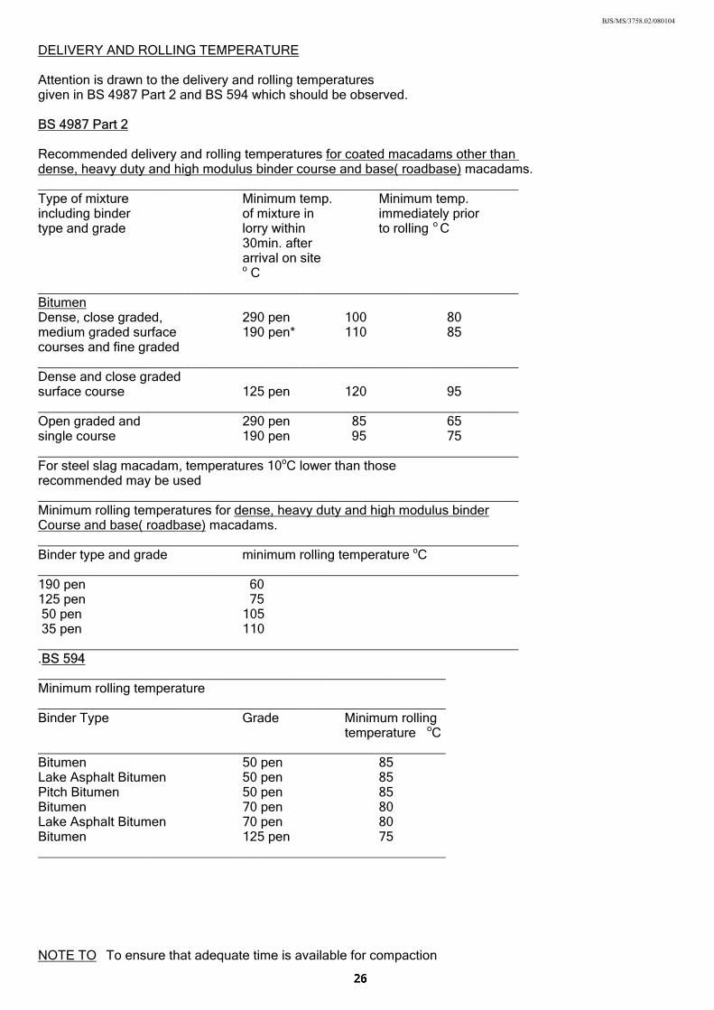
DELIVERY AND ROLLING TEMPERATURE Attention is drawn to the delivery and rolling temperatures given in BS 4987 Part 2 and BS 594 which should be observed. BS 4987 Part 2 Recommended delivery and rolling temperatures for coated macadams other than dense, heavy duty and high modulus binder course and base( roadbase) macadams. __________________________________________________________________ Type of mixture Minimum temp. Minimum temp. including binder of mixture in immediately prior type and grade lorry within to rolling o C 30min. after arrival on site o C __________________________________________________________________ Bitumen Dense, close graded, 290 pen 100 80 medium graded surface 190 pen* 110 85 courses and fine graded __________________________________________________________________ Dense and close graded surface course 125 pen 120 95 __________________________________________________________________ Open graded and 290 pen 85 65 single course 190 pen 95 75 __________________________________________________________________ For steel slag macadam, temperatures 10oC lower than those recommended may be used __________________________________________________________________ Minimum rolling temperatures for dense, heavy duty and high modulus binder Course and base( roadbase) macadams. __________________________________________________________________ Binder type and grade minimum rolling temperature oC __________________________________________________________________ 190 pen 60 125 pen 75 50 pen 105 35 pen 110 __________________________________________________________________ .BS 594 ________________________________________________________ Minimum rolling temperature ________________________________________________________ Binder Type Grade Minimum rolling temperature oC ________________________________________________________ Bitumen 50 pen 85 Lake Asphalt Bitumen 50 pen 85 Pitch Bitumen 50 pen 85 Bitumen 70 pen 80 Lake Asphalt Bitumen 70 pen 80 Bitumen 125 pen 75 ________________________________________________________ NOTE TO To ensure that adequate time is available for compaction
BJS/MS/3758.02/080104
BS 594 to be substantially completed before the temperature falls below the recommended minimum for rolling, a minimum delivery temperature, taken within 30 min. after arrival on site, of 130oC is recommended Inclement and cold weather working Laying shall be carried out with due regard to ambient weather General conditions so that materials can be properly compacted. If weather conditions are such that the performance of the pavement may be jeopardised, discontinue all operations. Laying of asphalt materials shall not be carried out if free Rain and standing water is present on the surface to be covered. standing Laying should also be avoided as far as is practicable during water heavy rain. If the wet weather threatens to be prolonged, laying of the coated macadam should be suspended.
For cold weather working a minimum of 24 hours notice is required Cold weather by the Engineer and generally the following shall apply:- working
Material for use in road pavements shall not be laid on any surface which is frozen or covered with ice.
No road pavement material in a frozen condition shall be incorporated in the Works but it may be used if acceptable when thawed out. Materials containing bitumen binders, shall not be laid if the temperature of the surface to be covered is at or below 2oC. Where however the surface is dry, unfrozen and free from ice, laying may proceed at air temperatures in the shade at or above -1oC on a rising thermometer. Additionally, unless the temperature of the surface to be covered is 5oC or more, rolled asphalt wearing course shall not be laid when the air temperature in the shade falls below 6oC. Laying operations below this air temperature may be allowed at the discretion of the Engineer. Joints in Flexible Surfacing When laying new material abutting freshly laid or old material Abutting freshly care shall be taken to secure good adhesion between joints by laid or cutting back the exposed joint, for a distance equal to the old material specified layer thickness, to a vertical face, discarding all loosened material and coating the vertical face completely with a suitable hot bitumen, or cold applied polymer modified intermediate or premium grade bitumen emulsion.
Further details:- for type 4 & 5 roads are given in a) below
type 3 roads are given in b) below Patches (all patches) are given in c) below Bituminous emulsion specification shown in d) below
Manhole covers, kerbs, channels, gullies and similar projections Other vertical against which asphalt materials are to abut shall be cleaned and faces painted with a thin uniform coating of 50(40/60) or 85(70/100) pen hot bitumen or, if approved in writing by the Engineer, cold applied thixotropic bitumen compound of similar grade,
BJS/MS/3758.02/080104
before the coated macadam is laid as indicated below. The new material shall be tamped around and against such projections so that, after final compaction, the finished surface shall be left flush or not exceeding 6mm above such projections. Manhole covers and similar fittings shall be adjusted to the correct levels before the wearing course is laid. a) ON TYPE 4 & 5 ROADS - The longitudinal centre line joint
will require sealing with hot run bitumen or an approved thixotropic cold compound.
b) ON TYPE 3 ROADS - All vertical joints to be sealed, AND INDUSTRIAL ESTATE kerb faces up to the finished ROADS water line and all iron work to be painted with hot run bitumen. c) PATCHES - Vertical joints to be painted with (ALL PATCHES) hot run or approved cold compound for all patches in all categories of
roads and footpaths - minimum size of patch 2m x 2m.
d) SPECIFICATION - To comply with BS594 : Part 2 : FOR JOINTS Clause 6.6 .
OR
BS 4987: Part 2 :Clauses 6.7 & 6.8 50(40/60) or 85(70/100) penetration
hot run bitumen.
OR
if approved in writing by the Engineer, cold applied thixotropic bitumen compound of similar grade
e.g. COLAS ( BITUKOLD LANSTAR)
- Bitumen cold joint primer or other similar approved.
BJS/MS/3758.02/080104
Trafficking of asphalt base(roadbase) or binder courses may be Trafficking permitted for a period of time before the surface course is laid. of asphalt They should be blinded with coated grit that shall be carried Base(Roadbase) out either by hand or mechanically with bituminous grit as and Binder specified in BS 4987,Part 2: 7.9 and the guidance given in Courses BS 4987, BS 4987, Part 2-B.5.4 before being open to traffic, with due regard being paid to the following :-
(a) On Type 3, 4 and industrial estate roads limestone and blast blast furnace slag aggregates are not allowed, and permitted
aggregates shall have a minimum P.S.V. of 55 if they are not to be covered within 6 weeks.
(b) On type 5 roads, limestone and blast furnace slag aggregates are not permitted in if the gradient exceeds 10% ( 1:10 ).
(c) If temporary trafficking causes polishing to the extent
that a satisfactory skid resistance is not maintained then the skidding resistance should be restored to a satisfactory level by surface dressing using chippings of minimum P.S.V. 55, or the application of other surface treatment as approved in writing by the Engineer.
Tolerance in surface levels
of pavement courses Road surface + 6mm except immediately adjacent to gullies
surface water channels and manholes where it shall be +6mm/ - 0mm.
Binder course + 6mm Base(roadbase) + 8mm Sub-base + 10mm/-30mm when under base( roadbase), otherwise + 10mm Formation + 20mm/-30mm Surface levels shall be checked for compliance with the tolerance requirements using the method described in paragraph 702.4 of the Highways Agency Specification for Highway Works. To meet the requirements, no measurement shall exceed the permitted tolerance. The finished surface shall be tested with a 3 metre long straight edge, laid longitudinally. For machine laid
Surface courses, the maximum depression under a 3 metre long straight edge shall not exceed 3mm.
Binder courses, the maximum depression under a 3 metre long straight edge shall not exceed 6mm.
For hand laid
Surface courses, the maximum depression under a 3 metre long straight edge shall not exceed 6mm.
Binder courses, the maximum depression under a 3 metre long straight edge shall not exceed 9mm

BJS/MS/3758.02/080104
Where these figures are exceeded the material shall be treated in accordance with the requirements for Rectification shown for :-
SUB BASE & BASE (ROADBASE) on page 4 SURFACING on page 24
NOTE: See separate requirements for Block Paving
BJS/MS/3758.02/080104
BLOCK PAVING
Shall be in accordance with the requirements of and British recommendations in BS 7533 except where it is varied standard for by the project specification. block paving
All block paving is to be built in accordance with the latest GENERAL requirements of The Highways Agency Specification For Highway Works:- clause 1107
The latest requirements of South Yorkshire Laboratory Specification For The Supply of Materials For Use In Highway Works.
and the following:-
Unless agreed in writing with the Engineer, all block paving shall be concrete block paving.
Pencil edge blocks shall be used For carriageway construction, sub-base shall be granular type 1 material in accordance with South Yorkshire Laboratory Specification No 19.
• Where the sub-base is to be subjected to residential traffic, • a 50mm thick course of 20mm dense asphalt binder • course shall be laid on top of the sub-base to provide • a running surface and protection to the sub-base. Where block paving is to be used for carriageway construction, The Contractor shall also refer to the following sections of this document:- Page 2 - Section 1 INTRODUCTION (Assumed CBRs) Subgrade and
and Sub-base (Frost susceptible sub-grade)
Page 4 - Section 2 MATERIALS- ROAD PAVEMENTS Sub-base and Page 21 - Section 7 FLEXIBLE CARRIAGEWAYS – SURFACING Binder course
The subgrade, sub-base and binder course shall be prepared so that:- (a) the surface levels are within the tolerances given in table 1 on page 35 (b) the longitudinal falls and crossfalls are such that no depressions hold water. Minimum recommended gradients:- Longitudinal fall ; 1.25% (1:80)
Crossfall ; 2.50% (1:40)
(c) the surface is tight and dense enough to prevent laying course (sand layer) material being lost into the lower layers during
construction and use; (d) provision is made to:
(1) drain water from any abutting laying course, e.g. by
BJS/MS/3758.02/080104
installation of drainage when the laying course is on impermeable foundations;
(2) prevent migration and loss of laying course material into the drainage system, e.g. by using a geotextile; The extent of the site prepared for block laying shall include Edge enough room to provide adequate foundations and backing restraints for any edge restraint. Edge restraints should be adequate to support traffic loads and to prevent loss of laying course material from beneath the surface course. Examples are kerbs, combined kerbs and channels, established structures or rigid abutments such as paving blocks fixed vertically, bedded on and haunched with concrete. Do not vibrate the surface course until the edge restraint, together with any concrete haunching, has gained sufficient strength. Are to be found in section 13 Standard Construction details LAYING COURSE ( SAND BEDDING LAYER) Laying course ( and jointing material) shall be naturally occurring Material sand in accordance with the recommendations given in B.S.7533-3 and Table 2 on page 30 of this specification. The moisture content of the laying course should be as Moisture uniform as possible and the material should be moist content without being saturated. All material to be used must be stockpiled under a cover. Stockpiling Construct the laying course so that after compaction Screeding it forms a layer approximately 35mm thick below the paving blocks. Where closer tolerances than those given in table 1 on page 30 for the level of the sub-base have been achieved, or where a binder course has been used, a thinner laying course can be used. However, in no case should the material be less than 25mm thick at any point.
BJS/MS/3758.02/080104
The object of screeding the laying course is to produce a uniform surface, to the specified design profiles and falls, at a uniform degree of compaction. When setting up screeding rails, allowance should be made for the subsequent compaction of the laying course
If any disturbance of the prepared laying course by pedestrian or wheeled traffic occurs, prior to placing paving blocks, re-screed areas of laying course material.
Construct the laying course using one of the methods described below:-
LAYING METHODS
Spread the material loose in a uniform layer to approximately Precompaction the required final depth below the surface profile. Compact this layer using a vibrating plate compactor. Spread a further layer of material about 15mm thick and screed it to create a loose surface on which the paving blocks can be placed. Spread the material loose in a uniform layer, and screed it to the Compaction thickness required to give the specified design thickness after the after laying paving blocks have been laid and vibrated into place. The precompaction method is preferable because it helps to ensure uniform density and compaction of the laying course and hence improves surface tolerances. Where a nominal compacted thickness of 35mm is to be used, Trial areas if previous experience of a particular material is lacking, a small trial area will be needed to determine the allowance. The area of laying course prepared should generally Block laying be such that its boundary is not less than 1m ahead of the bounderies laying face, except at the end of the working period when the boundary should be no more than 1m ahead of the laying face. The working edge should be protected overnight and it may be necessary to remove an area of blocks prior to screeding for the days operation.
BJS/MS/3758.02/080104
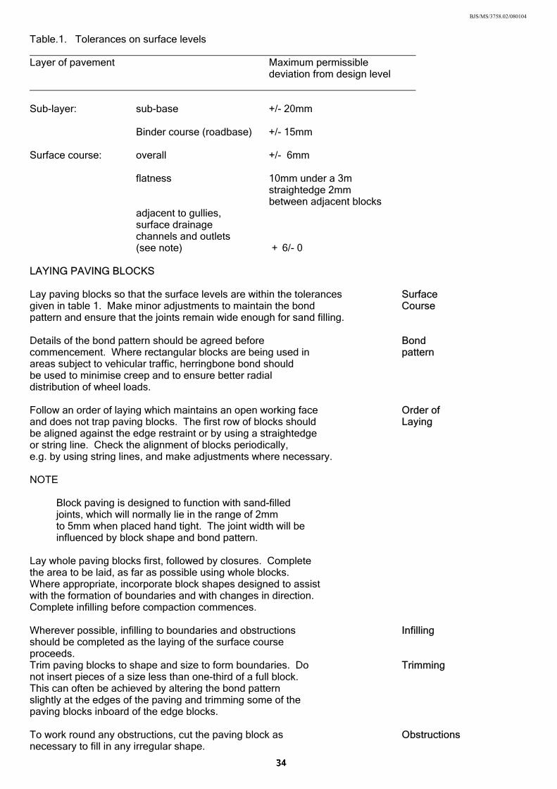
Table.1. Tolerances on surface levels ____________________________________________________________________ Layer of pavement Maximum permissible deviation from design level ____________________________________________________________________ Sub-layer: sub-base +/- 20mm Binder course (roadbase) +/- 15mm Surface course: overall +/- 6mm flatness 10mm under a 3m straightedge 2mm between adjacent blocks adjacent to gullies, surface drainage channels and outlets (see note) + 6/- 0 LAYING PAVING BLOCKS
Lay paving blocks so that the surface levels are within the tolerances Surface given in table 1. Make minor adjustments to maintain the bond Course pattern and ensure that the joints remain wide enough for sand filling. Details of the bond pattern should be agreed before Bond commencement. Where rectangular blocks are being used in pattern areas subject to vehicular traffic, herringbone bond should be used to minimise creep and to ensure better radial distribution of wheel loads. Follow an order of laying which maintains an open working face Order of and does not trap paving blocks. The first row of blocks should Laying be aligned against the edge restraint or by using a straightedge or string line. Check the alignment of blocks periodically, e.g. by using string lines, and make adjustments where necessary. NOTE
Block paving is designed to function with sand-filled joints, which will normally lie in the range of 2mm to 5mm when placed hand tight. The joint width will be influenced by block shape and bond pattern. Lay whole paving blocks first, followed by closures. Complete the area to be laid, as far as possible using whole blocks. Where appropriate, incorporate block shapes designed to assist with the formation of boundaries and with changes in direction. Complete infilling before compaction commences. Wherever possible, infilling to boundaries and obstructions Infilling should be completed as the laying of the surface course proceeds. Trim paving blocks to shape and size to form boundaries. Do Trimming not insert pieces of a size less than one-third of a full block. This can often be achieved by altering the bond pattern slightly at the edges of the paving and trimming some of the paving blocks inboard of the edge blocks. To work round any obstructions, cut the paving block as Obstructions necessary to fill in any irregular shape.
BJS/MS/3758.02/080104
Fully compact the surface course using a plate compactor with Compaction a plate area of not less than 0.25m2 , transmitting an effective of Block force of not less than 75kN/m2 of plate at a frequency of Paving vibration in the range 75Hz to 100Hz. Alternatively, use any compacting equipment which will achieve the same degree of compaction or better. It is important to fill the lower portion of the block-to-block joint with the laying course material. Carry out compaction as soon as possible after laying but not within 1m of any laying face. Apart from this edge strip, do not leave any area of paving uncompacted at the completion of the day’s work. Ensure that the finished surface levels are within the tolerances given in table 1 on Page 30. The contact area of a plate compactor may be Measuring measured by standing the plate on a flat smooth contact area level surface and sliding a piece of card in from of plate both front and rear until it meets the position compactor where the plate touches the ground. After compaction of the surface course, spread sand or crushed Joint rock fines over the surface and brush it into the joints. Materials Filling complying with the grading in table 2 shall be used. Do not use a sand which might stain the pavement surface, if this is an important consideration. NOTE.1. Filling between the joints is very important. It interlocks
the paving and helps impart static load bearing characteristics. The use of dry material will assist in rapid joint penetration.
Vibrate the block paving to ensure complete filling of the block-to-block joint by the surface-applied sand. Where necessary add further sand and re-vibrate the paving. Complete joint filling and final compaction as soon as practicable after laying. NOTE.2. Where block paving is to be used by industrial
vehicles imposing exceptionally high point loads, it is advisable to further compact the entire pavement after joint filling. NOTE.3. Concrete blocks should not be vacuumed for at least three weeks after laying in order to reduce the risk of jointing sand being lost.
It may be necessary to provide joint stabilisation compound and block surface sealants at the discretion of the Engineer. Table 2 - Laying course sand etc. The surface course shall be inspected after an early period of traffic Early use and additional sand filling brushed in where necessary Trafficking Table 2 Laying course sand and joining sand to comply with BS7533: Part 3: Annex D
BJS/MS/3758.02/080104
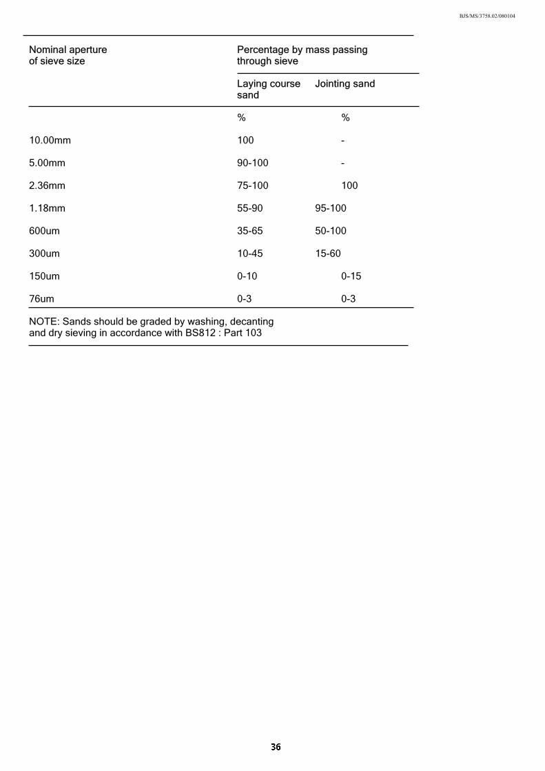
Nominal aperture Percentage by mass passing of sieve size through sieve Laying course Jointing sand sand
% % 10.00mm 100 - 5.00mm 90-100 - 2.36mm 75-100 100 1.18mm 55-90 95-100 600um 35-65 50-100 300um 10-45 15-60 150um 0-10 0-15 76um 0-3 0-3 NOTE: Sands should be graded by washing, decanting and dry sieving in accordance with BS812 : Part 103
BJS/MS/3758.02/080104
8. FOOTWAYS AND VEHICLE CROSSINGS
GENERAL
All footways and vehicle crossings are to be built in accordance with the latest requirements of Series 1100 Kerbs Footways and Paved Areas.of The Specification For Highway Works:- The latest requirements of South Yorkshire Laboratory Specification For The Supply of Materials For Use In Highway Works.
and the following:- Drawings showing details of proposed footways and vehicle Drawings crossings areas shall be submitted to The Engineer prior to commencement of the works. FOOTWAY EDGING Precast concrete edging as previously specified shall be laid Fixing closely jointed between footpath surfaces and verges or elsewhere if directed by the Engineer. The edging shall be solidly bedded on concrete 100mm thick and haunched (both sides) with 75mm thick concrete so as to ensure that it does not move during the footpath construction and shall be laid to correct alignment and level. After completion, any unit found to be more than 6mm out of line or level at either end of the unit shall be lifted and re-laid. The Contractor shall be responsible for rectifying any movement Rectification that occurs prior to and during the maintenance period. FOOTWAYS AND HARDENED MARGINS The sub-base for both footways and hardened margins are to be Sub-Base formed with Type 1 sub-base material complying with South Laboratory specification No 19, properly compacted. The completed surface shall be free from irregularities and loose material and is to be true to cross section, line and level. Note; Sub-Base is to extend under concrete bedding for kerbs and edging. ASPHALT MATERIALS Binder courses for asphalt footways shall be dense binder Binder course that shall be laid in accordance with BS 4987-2. course 6mm size Dense Surface Course that shall be laid in accordance Surface with BS 4987-2 and laid evenly on the binder course to give Course for a minimum compacted thickness of 25mm. Where the Footways surfacing abuts kerbs, the final surface shall be between 2mm and 3mm proud of the top of the kerb and shall be true to level and the required crossfall.(3% min - 4% max). Compaction shall comply with B.S. 4987-2 Clause 7. Compaction (Please refer to tables for delivery & rolling temperatures of asphalt extracted from B S 4987 on page 22) materials
The recommended roller for all footway and footpath works Recommended shall be a double drum vibratory roller TV.75 or BW75ADL rollers (articulated) or similar approved.
BJS/MS/3758.02/080104
FLAGS It may be necessary to lay a bonding course to avoid "creep" in large areas on steep gradients. Bonded courses of flags properly bedded on the prepared base with a 10mm sand and cement mortar bed, closely jointed, and driven into position with a heavy maul. The outer edge of flags where the footway abuts kerbs, is to be kept level with the latter and the footway shall be laid true to level and required crossfall. The flags shall be laid in courses at right angles to the kerbs.
BLOCK PAVING
Block paving may be used as an alternative i.e. 60mm thick blocks (Pencil Edge) on 35mm compacted sand on 150mm of Type 1 sub-base to South Yorkshire Laboratory Specification Number 19. VEHICLE CROSSINGS Footway Vehicle Crossings subjected to more than private car traffic shall be constructed to the same specification as the adjacent carriageway. Footway vehicle crossings subjected to private car traffic only shall be constructed in accordance with the Standard Details. PEDESTRIAN CROSSINGS Dropped kerbs to facilitate the passage of wheelchairs and prams, shall be installed at all road junctions and other pedestrian crossing points, as directed by the Engineer, and shall be constructed in accordance with the Standard Details. (Maximum upstand 6mm). LAYING AND COMPACTION OF ASPHALT MATERIALS Materials shall be compacted as soon as rolling can be effected Compaction without causing undue displacement of the material and at no less than the minimum rolling temperature. The material shall be uniformly compacted by an appropriate roller capable of meeting the air void requirements across the full width. The method of laying shall ensure that air voids of compacted Air voids asphalt materials shall be in the range of 2% - 8%. Not more than 1 in 10 results will be permitted above 8% and no result is allowed over 10%. Delivery and rolling temperatures to be in accordance with the Delivery and tables shown on page 27. rolling temperatures
BJS/MS/3758.02/080104
9. HIGHWAY VERGES AND PLANTING
GRASS AND GROUND COVER PLANTS All grassed and planted areas are to be built in accordance with General the latest requirements of Series 3000 of The Highways Agency Specification For Highway Works where it does not conflict with BS 4428:1989 And the following:- Drawings/planting plans indicating species, size, spacing/m2 Drawings with appropriate schedules and appendices shall be submitted for specific approval for the scheme prior to the commencement of works. Topsoil to comply with BS 3882 figure K1 for texture and Topsoil And BS1377 part 3 pH
Depth to be 450mm for shrubs, to be top quality vegetable soil maximum stone content 5% dry weight, not more than 50mm any dimension.
Soil containing Japanese Knot weed and Mares Tail will be rejected. The surface is to be cultivated down to a minimum depth of 150mm, Cultivation bring to fine tilth and regulate to evenly running levels. Clear out all weeds, large stones, broken brick, perennial weeds and roots. British conifer bark mulch containing less than 5% wood, Bark mulch minimum thickness of 75mm over entire planted area, and Fertilizer supply ENMAG (or similar approved) and mix into bark at a rate of 50 g/m2
Approved fertiliser evenly distributed at not less than 68 grammes per m2 (20.10.10). Approved species of plants should be well established and Plants free from disease, with a minimum 3 good growing points.
Size & spacing:- Ground cover 200 - 300mm - 15/m2 Shrubs (medium) 450 - 600mm - 6/m2 Hedging Plants 600 - 900mm - 4/Lin-m The area is to be well maintained free from grass, weeds Maintenance and litter and watered in dry weather. GRASS Nothing less than 900mm width. Minimum width Soil depth of 150mm reduced to a fine tilth, free from Topsoil stones and other debris. After settlement, finished level to be 10mm above adjacent Finished concrete edging/kerb. level Approved fertiliser evenly distributed at not less than Fertiliser 68 grammes per m2 (20.10.10). Low maintenance grass seed or turf shall be used. Seed

BJS/MS/3758.02/080104
During the maintenance period all verges are to be maintained Maintenance in healthy condition, free from weeds and grass verges are to period be cut regularly.
At the end of the maintenance period there should be 100% cover of planted and grassed areas which are 97% weed free, with no dead or diseased plants.
A tree planting Specification is available on request. Tree planting Specification

BJS/MS/3758.02/080104
10. STREET LIGHTING
All street lighting works are to be in accordance with the latest General requirements of Series 1300 & 1400 of The Highways Agency Specification For Highway works. And the following:- The design and installation of street lighting schemes is normally Design undertaken by The Highway Authority. An early approved design which may include illuminated traffic signs is required to avoid any abortive works.
A list of acceptable equipment is available, on request. Developers Acceptable wishing to deviate from this list should discuss the matter with the Equipment Lighting Engineer at the earliest opportunity.
The installation of street lighting should be related closely to the Installation occupation of dwellings and must not be left until the development as a whole is nearing completion. Where the work is to be carried out by the Developer, the Engineer should be asked to approve the positions of the columns on site prior to erection. The Developer must make all the necessary arrangements with the Electricity Company for the connection of the supply. Alternatively, subject to receipt of an official order, the Highway Authority will provide and install equipment on behalf of the Developer, and make the necessary arrangements for the connection of the electricity supply.
Lighting columns should be located within the limits of the highway, normally at the back edge of footway or verge. In certain instances, however, it may be acceptable to attach lighting units to buildings, for example in mews courts. This will normally require a way-leave agreement between the owner, Electricity Company and the Highway Authority.
BJS/MS/3758.02/080104
11. COMPLETION OF WORKS
Grass verges are to be rolled during the progress of the work and Maintenance during the period of maintenance, and well watered in dry weather. of Verges The Contractor shall remove and replace any areas that are not in a healthy condition, up to the end of the period of maintenance. The grass is to be cut on a regular basis and not less than 4 times in 12 months. CLEANLINESS OF THE SITE The whole of the works shall be left on completion in a clean and General tidy condition. It is an offence to under Section 151 of the Highways Act 1980 Deleterious to deposit deleterious material on the Public Highway. The matter Developer must ensure that appropriate measures for cleaning are provided within the CDM Regulations. It is normal for this to be a condition of the planning permission.
The Contractor is to cleanse the carriageway, footway and verges Cleansing regularly during the progress of the works, as required during their term of maintenance and once thoroughly immediately before the termination of the maintenance period. PROVING DRAINS On completion of the works all drains, manholes and gullies shall Rodding be rodded, flushed with water and left clean and free from obstruction.
BJS/MS/3758.02/080104
12. MISCELLANEOUS
Street lighting, traffic signs, road markings and street name Street Lighting plates shall be provided at the expense of the Developer signs etc. All these items shall comply with the edition of the relevant British Standard and Specification for Highway Works current at the time of construction for illuminated signs (see page 1). Street name plates are to be erected prior to occupancy of any Street name properties. plates When requested by the Engineer, grit bins shall also be provided. Grit bins at the expense of the Developer.
Grit Bins will generally be required on roads and/or footpaths with a gradient steeper than 1 in 12 ( 8% ) and must be maintained and kept full of salt by The Developer until adoption. Further details in this connection can be obtained from the Engineer upon request. Any retaining wall to which Section 167 of the Highways Act Retaining Walls 1980 applies or any other retaining wall or Structure which the Developer intends to offer for adoption by the Highway Authority must be approved by the Engineer. Notes for guidance on such matters are available on request. The extent of the adoptable areas are to be clearly defined Definition of to the satisfaction of the Engineer. Highway Boundary Adoptable parking areas adjacent to roads must be surfaced with a Parking Areas material which is not susceptible to damage by oil droppings and such surfacings should preferably be brindle coloured block paving with approved edge restraint.
BJS/MS/3758.02/080104
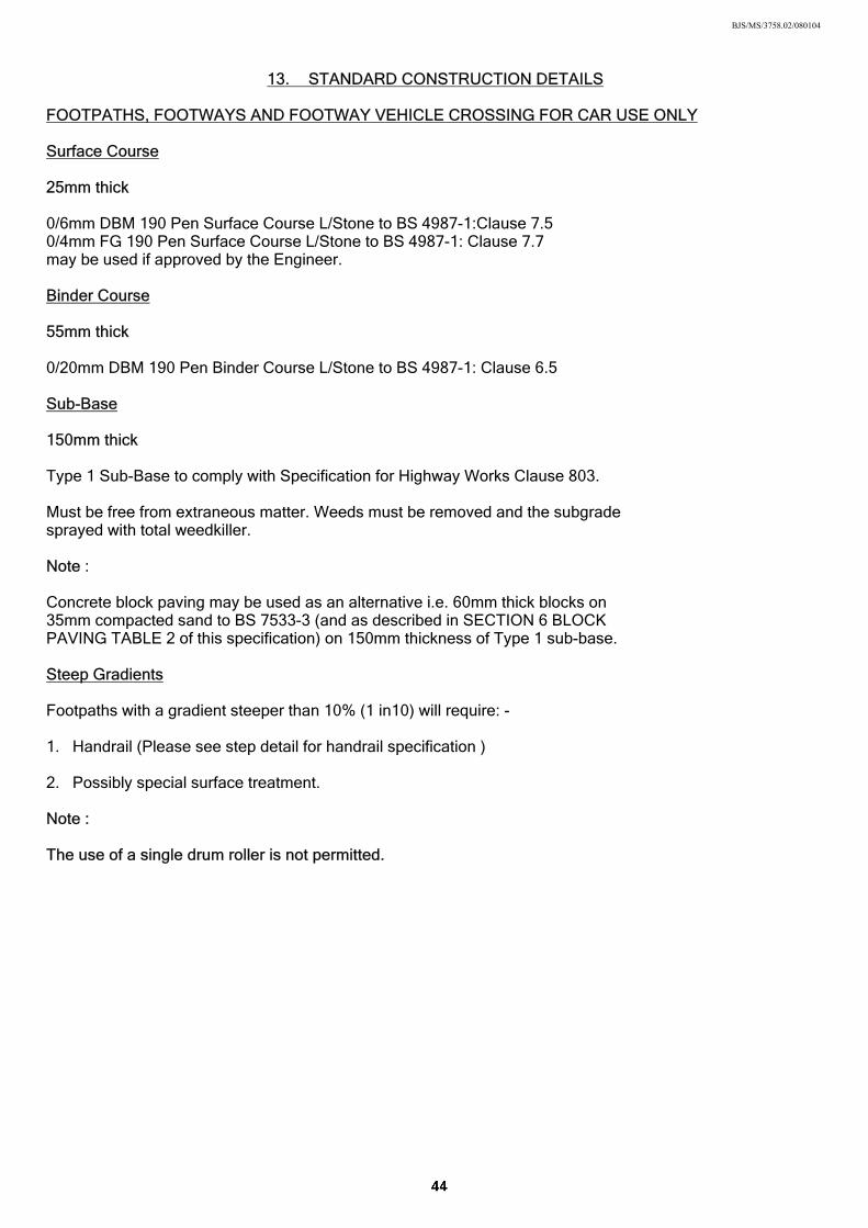
13. STANDARD CONSTRUCTION DETAILS
FOOTPATHS, FOOTWAYS AND FOOTWAY VEHICLE CROSSING FOR CAR USE ONLY Surface Course 25mm thick 0/6mm DBM 190 Pen Surface Course L/Stone to BS 4987-1:Clause 7.5 0/4mm FG 190 Pen Surface Course L/Stone to BS 4987-1: Clause 7.7 may be used if approved by the Engineer. Binder Course 55mm thick 0/20mm DBM 190 Pen Binder Course L/Stone to BS 4987-1: Clause 6.5 Sub-Base 150mm thick Type 1 Sub-Base to comply with Specification for Highway Works Clause 803. Must be free from extraneous matter. Weeds must be removed and the subgrade sprayed with total weedkiller. Note : Concrete block paving may be used as an alternative i.e. 60mm thick blocks on 35mm compacted sand to BS 7533-3 (and as described in SECTION 6 BLOCK PAVING TABLE 2 of this specification) on 150mm thickness of Type 1 sub-base. Steep Gradients Footpaths with a gradient steeper than 10% (1 in10) will require: - 1. Handrail (Please see step detail for handrail specification )
2. Possibly special surface treatment. Note : The use of a single drum roller is not permitted.
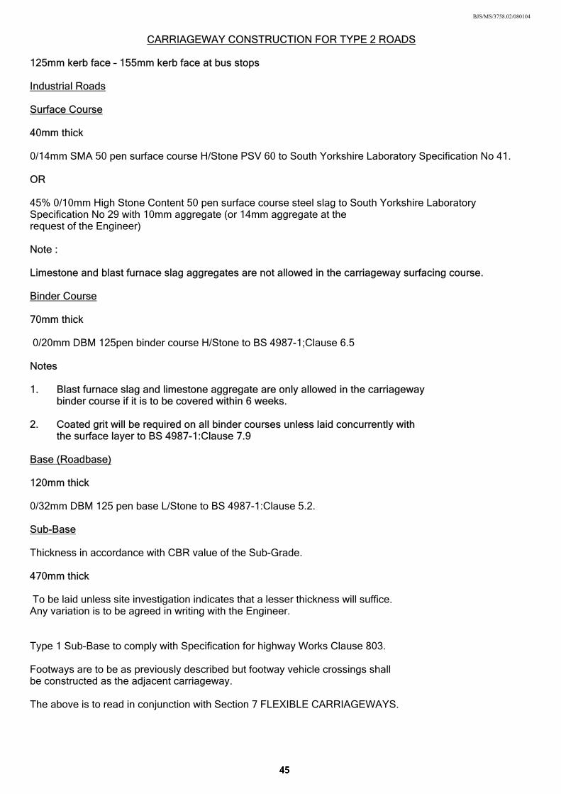
BJS/MS/3758.02/080104
CARRIAGEWAY CONSTRUCTION FOR TYPE 2 ROADS 125mm kerb face – 155mm kerb face at bus stops Industrial Roads Surface Course 40mm thick 0/14mm SMA 50 pen surface course H/Stone PSV 60 to South Yorkshire Laboratory Specification No 41. OR 45% 0/10mm High Stone Content 50 pen surface course steel slag to South Yorkshire Laboratory Specification No 29 with 10mm aggregate (or 14mm aggregate at the request of the Engineer) Note : Limestone and blast furnace slag aggregates are not allowed in the carriageway surfacing course. Binder Course 70mm thick 0/20mm DBM 125pen binder course H/Stone to BS 4987-1;Clause 6.5 Notes 1. Blast furnace slag and limestone aggregate are only allowed in the carriageway binder course if it is to be covered within 6 weeks. 2. Coated grit will be required on all binder courses unless laid concurrently with
the surface layer to BS 4987-1:Clause 7.9 Base (Roadbase) 120mm thick 0/32mm DBM 125 pen base L/Stone to BS 4987-1:Clause 5.2. Sub-Base Thickness in accordance with CBR value of the Sub-Grade. 470mm thick To be laid unless site investigation indicates that a lesser thickness will suffice. Any variation is to be agreed in writing with the Engineer. Type 1 Sub-Base to comply with Specification for highway Works Clause 803. Footways are to be as previously described but footway vehicle crossings shall be constructed as the adjacent carriageway. The above is to read in conjunction with Section 7 FLEXIBLE CARRIAGEWAYS.
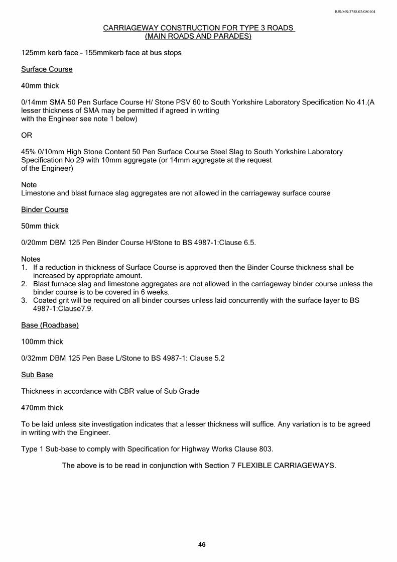
BJS/MS/3758.02/080104
CARRIAGEWAY CONSTRUCTION FOR TYPE 3 ROADS (MAIN ROADS AND PARADES)
125mm kerb face – 155mmkerb face at bus stops Surface Course 40mm thick 0/14mm SMA 50 Pen Surface Course H/ Stone PSV 60 to South Yorkshire Laboratory Specification No 41.(A lesser thickness of SMA may be permitted if agreed in writing with the Engineer see note 1 below) OR 45% 0/10mm High Stone Content 50 Pen Surface Course Steel Slag to South Yorkshire Laboratory Specification No 29 with 10mm aggregate (or 14mm aggregate at the request of the Engineer) Note Limestone and blast furnace slag aggregates are not allowed in the carriageway surface course Binder Course 50mm thick 0/20mm DBM 125 Pen Binder Course H/Stone to BS 4987-1:Clause 6.5. Notes 1. If a reduction in thickness of Surface Course is approved then the Binder Course thickness shall be
increased by appropriate amount. 2. Blast furnace slag and limestone aggregates are not allowed in the carriageway binder course unless the
binder course is to be covered in 6 weeks. 3. Coated grit will be required on all binder courses unless laid concurrently with the surface layer to BS
4987-1:Clause7.9. Base (Roadbase) 100mm thick 0/32mm DBM 125 Pen Base L/Stone to BS 4987-1: Clause 5.2 Sub Base Thickness in accordance with CBR value of Sub Grade 470mm thick To be laid unless site investigation indicates that a lesser thickness will suffice. Any variation is to be agreed in writing with the Engineer. Type 1 Sub-base to comply with Specification for Highway Works Clause 803.
The above is to be read in conjunction with Section 7 FLEXIBLE CARRIAGEWAYS.
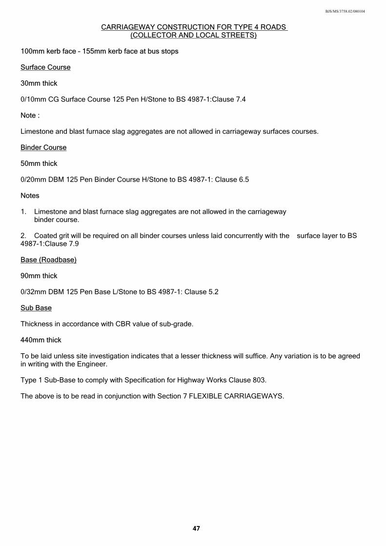
BJS/MS/3758.02/080104
CARRIAGEWAY CONSTRUCTION FOR TYPE 4 ROADS (COLLECTOR AND LOCAL STREETS)
100mm kerb face – 155mm kerb face at bus stops Surface Course 30mm thick 0/10mm CG Surface Course 125 Pen H/Stone to BS 4987-1:Clause 7.4 Note : Limestone and blast furnace slag aggregates are not allowed in carriageway surfaces courses. Binder Course 50mm thick 0/20mm DBM 125 Pen Binder Course H/Stone to BS 4987-1: Clause 6.5 Notes 1. Limestone and blast furnace slag aggregates are not allowed in the carriageway binder course. 2. Coated grit will be required on all binder courses unless laid concurrently with the surface layer to BS 4987-1:Clause 7.9 Base (Roadbase) 90mm thick 0/32mm DBM 125 Pen Base L/Stone to BS 4987-1: Clause 5.2 Sub Base Thickness in accordance with CBR value of sub-grade. 440mm thick To be laid unless site investigation indicates that a lesser thickness will suffice. Any variation is to be agreed in writing with the Engineer. Type 1 Sub-Base to comply with Specification for Highway Works Clause 803. The above is to be read in conjunction with Section 7 FLEXIBLE CARRIAGEWAYS.
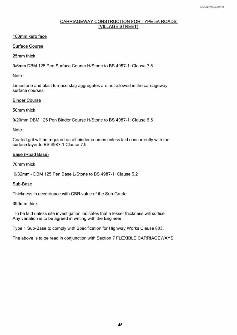
BJS/MS/3758.02/080104
CARRIAGEWAY CONSTRUCTION FOR TYPE 5A ROADS
(VILLAGE STREET) 100mm kerb face Surface Course 25mm thick 0/6mm DBM 125 Pen Surface Course H/Stone to BS 4987-1: Clause 7.5 Note : Limestone and blast furnace slag aggregates are not allowed in the carriageway surface courses. Binder Course 50mm thick 0/20mm DBM 125 Pen Binder Course H/Stone to BS 4987-1: Clause 6.5 Note : Coated grit will be required on all binder courses unless laid concurrently with the surface layer to BS 4987-1:Clause 7.9 Base (Road Base) 70mm thick 0/32mm – DBM 125 Pen Base L/Stone to BS 4987-1: Clause 5.2 Sub-Base Thickness in accordance with CBR value of the Sub-Grade 390mm thick To be laid unless site investigation indicates that a lesser thickness will suffice. Any variation is to be agreed in writing with the Engineer. Type 1 Sub-Base to comply with Specification for Highway Works Clause 803. The above is to be read in conjunction with Section 7 FLEXIBLE CARRIAGEWAYS
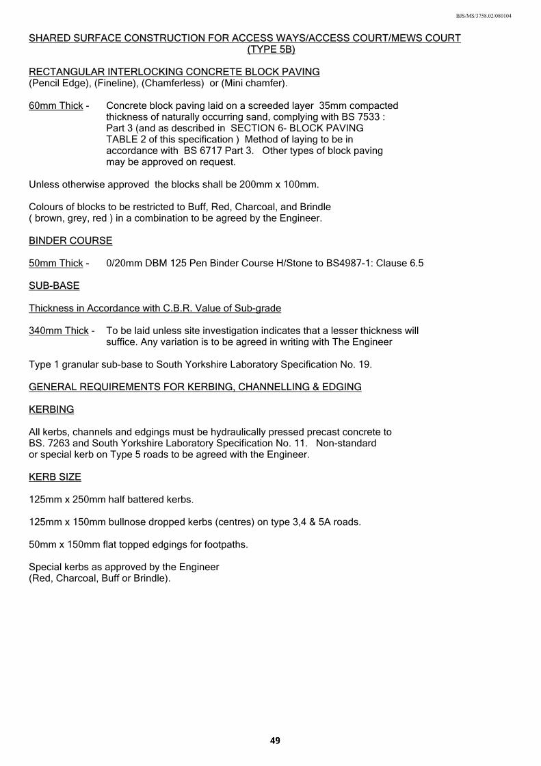
BJS/MS/3758.02/080104
SHARED SURFACE CONSTRUCTION FOR ACCESS WAYS/ACCESS COURT/MEWS COURT (TYPE 5B)
RECTANGULAR INTERLOCKING CONCRETE BLOCK PAVING (Pencil Edge), (Fineline), (Chamferless) or (Mini chamfer). 60mm Thick - Concrete block paving laid on a screeded layer 35mm compacted
thickness of naturally occurring sand, complying with BS 7533 : Part 3 (and as described in SECTION 6- BLOCK PAVING TABLE 2 of this specification ) Method of laying to be in accordance with BS 6717 Part 3. Other types of block paving may be approved on request.
Unless otherwise approved the blocks shall be 200mm x 100mm. Colours of blocks to be restricted to Buff, Red, Charcoal, and Brindle ( brown, grey, red ) in a combination to be agreed by the Engineer. BINDER COURSE 50mm Thick - 0/20mm DBM 125 Pen Binder Course H/Stone to BS4987-1: Clause 6.5 SUB-BASE Thickness in Accordance with C.B.R. Value of Sub-grade 340mm Thick - To be laid unless site investigation indicates that a lesser thickness will
suffice. Any variation is to be agreed in writing with The Engineer Type 1 granular sub-base to South Yorkshire Laboratory Specification No. 19. GENERAL REQUIREMENTS FOR KERBING, CHANNELLING & EDGING KERBING All kerbs, channels and edgings must be hydraulically pressed precast concrete to BS. 7263 and South Yorkshire Laboratory Specification No. 11. Non-standard or special kerb on Type 5 roads to be agreed with the Engineer. KERB SIZE 125mm x 250mm half battered kerbs. 125mm x 150mm bullnose dropped kerbs (centres) on type 3,4 & 5A roads. 50mm x 150mm flat topped edgings for footpaths. Special kerbs as approved by the Engineer (Red, Charcoal, Buff or Brindle).
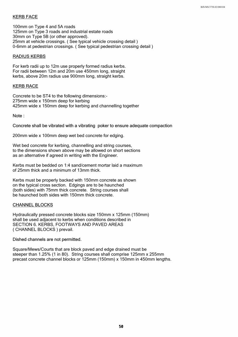
BJS/MS/3758.02/080104
KERB FACE 100mm on Type 4 and 5A roads 125mm on Type 3 roads and industrial estate roads 30mm on Type 5B (or other approved). 25mm at vehicle crossings. ( See typical vehicle crossing detail ) 0-6mm at pedestrian crossings. ( See typical pedestrian crossing detail ) RADIUS KERBS For kerb radii up to 12m use properly formed radius kerbs. For radii between 12m and 20m use 450mm long, straight kerbs, above 20m radius use 900mm long, straight kerbs. KERB RACE Concrete to be ST4 to the following dimensions:- 275mm wide x 150mm deep for kerbing 425mm wide x 150mm deep for kerbing and channelling together Note : Concrete shall be vibrated with a vibrating poker to ensure adequate compaction 200mm wide x 100mm deep wet bed concrete for edging. Wet bed concrete for kerbing, channelling and string courses, to the dimensions shown above may be allowed on short sections as an alternative if agreed in writing with the Engineer. Kerbs must be bedded on 1:4 sand/cement mortar laid a maximum of 25mm thick and a minimum of 13mm thick. Kerbs must be properly backed with 150mm concrete as shown on the typical cross section. Edgings are to be haunched (both sides) with 75mm thick concrete. String courses shall be haunched both sides with 150mm thick concrete. CHANNEL BLOCKS
Hydraulically pressed concrete blocks size 150mm x 125mm (150mm) shall be used adjacent to kerbs when conditions described in SECTION 6. KERBS, FOOTWAYS AND PAVED AREAS ( CHANNEL BLOCKS ) prevail.
Dished channels are not permitted. Square/Mews/Courts that are block paved and edge drained must be steeper than 1.25% (1 in 80). String courses shall comprise 125mm x 255mm precast concrete channel blocks or 125mm (150mm) x 150mm in 450mm lengths.
BJS/MS/3758.02/080104
97. MANHOLES AND HIGHWAY DRAINS Generally all manholes and highway drains shall be constructed and laid in accordance with current edition of Sewers for Adoption. Clay pipes and fittings shall be in accordance with the requirements
of BS.65. Concrete pipes and fittings shall be in accordance with the requirements of BS. 5911 and shall be fitted with approved flexible joints.
Plastic pipes and fittings shall be in accordance with the requirements of
EN1401-1 BS 4660 and the water industry specification W1S 4/35/01. Gully connections shall be surrounded with 150mm thickness ST4 concrete and include a flexible joint on each pipe. Where the cover to a pipeline laid under a carriageway is 1.2m or less, it shall be surrounded with 150mm thickness ST4 concrete.
Where a concrete surround is not required, pipelines shall be laid on
a concrete or granular bed designed in accordance with “Simplified Tables of External Loads or Buried Pipelines” issued by the Transport Research Laboratory. Gully connections should not exceed 20m in length.
Drain trenches are not to be backfilled until the pipework has been
approved by the Engineer which may include air and/or water tests. Trenches in the carriageways are to be backfilled with Type 2 granular material to South Yorkshire Laboratory Specification No. 20
(or other material approved in writing by the Engineer) which shall contain a minimum of 10% of material retained on a 37.5mm BS Sieve.
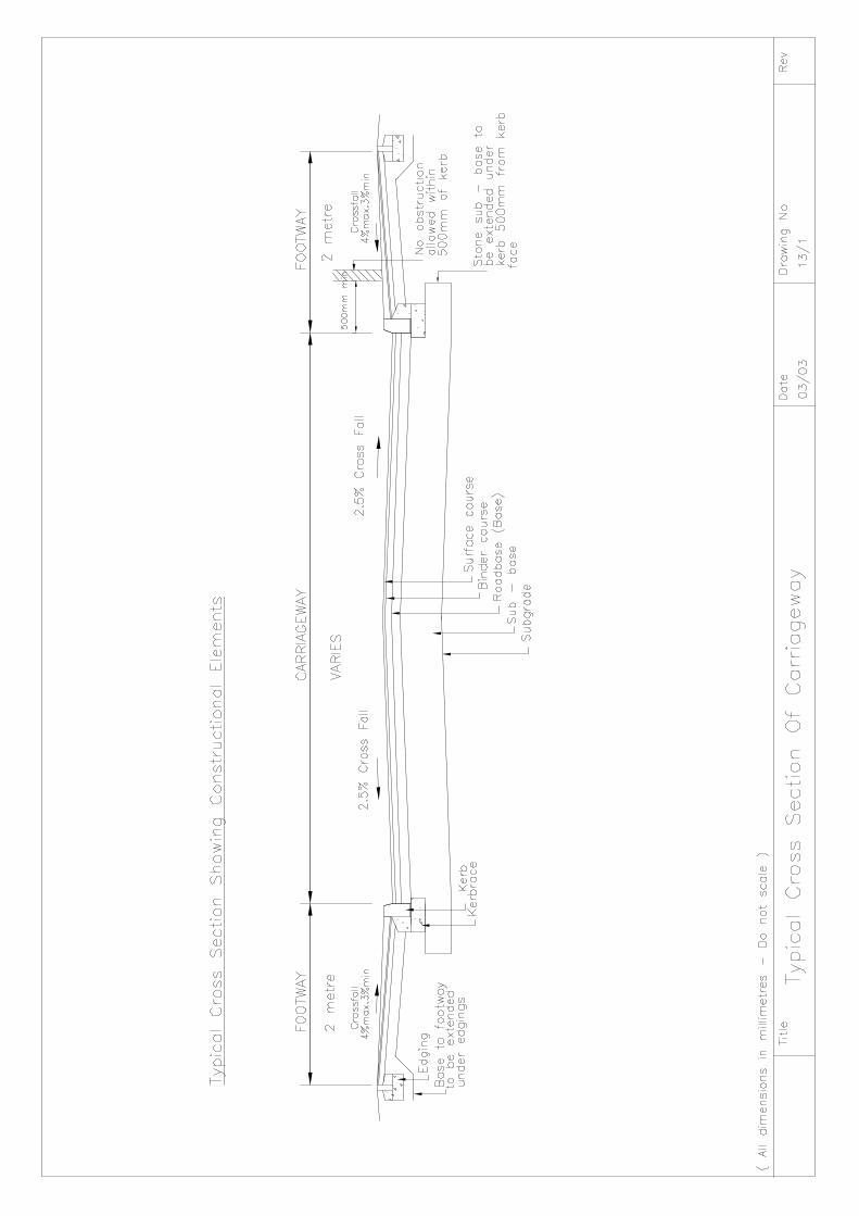
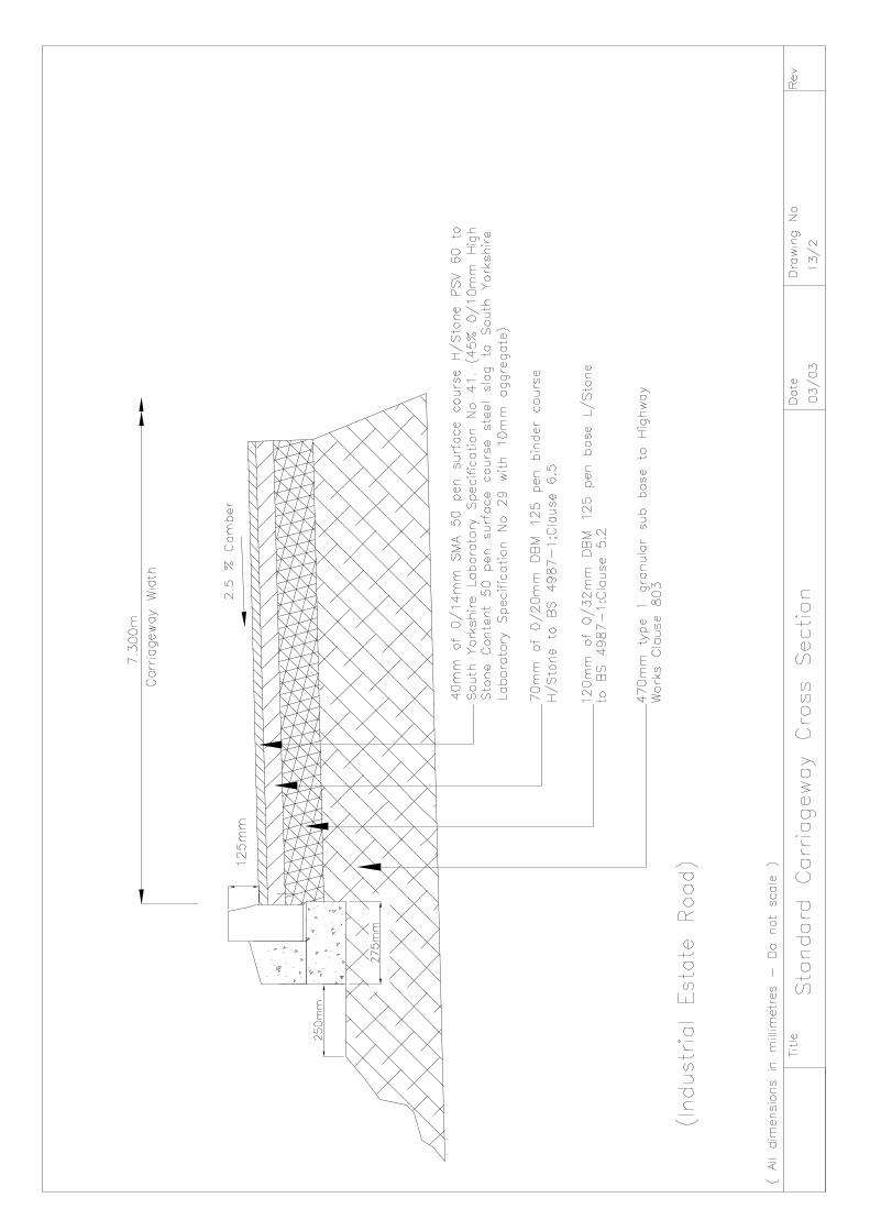
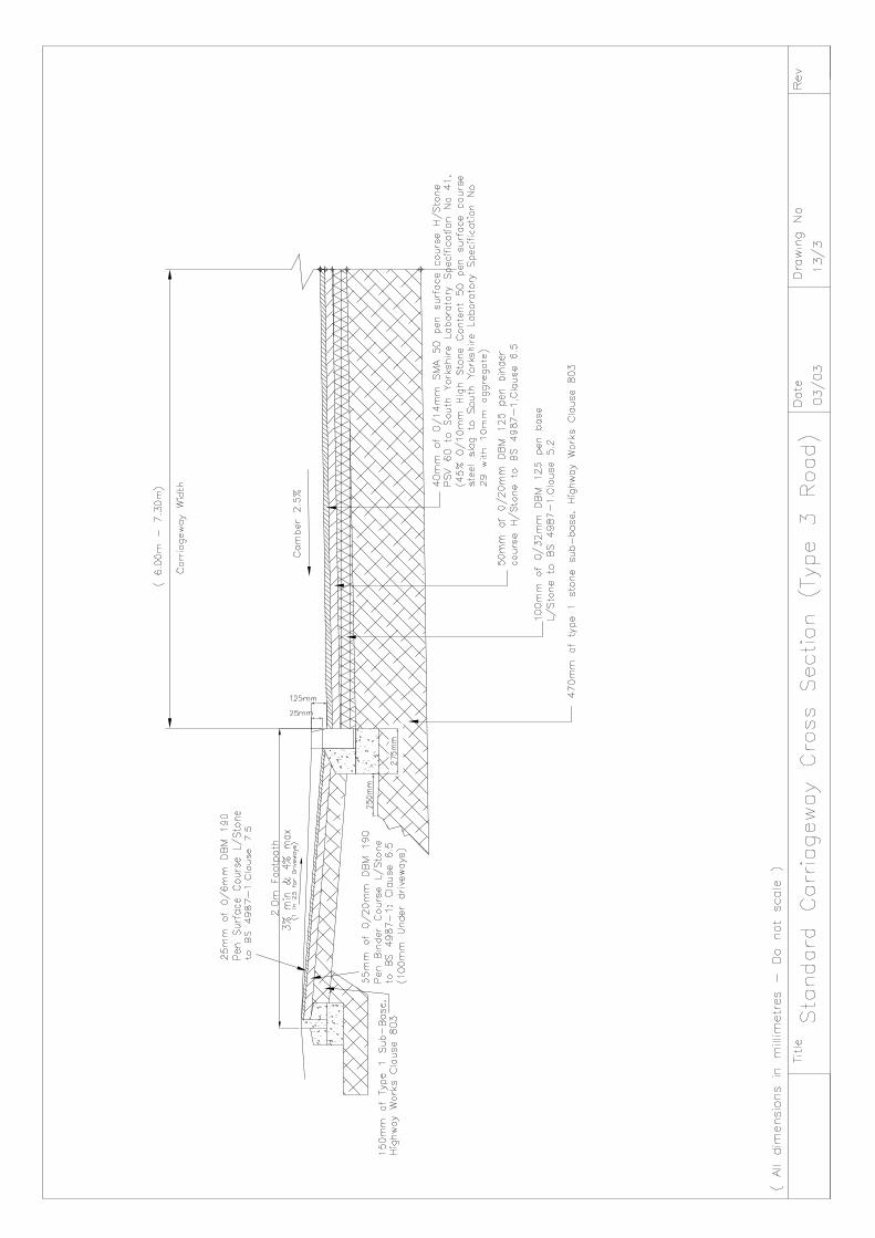
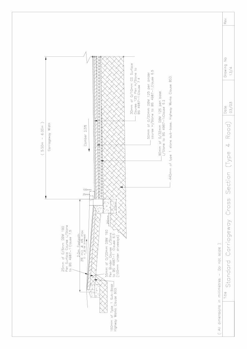
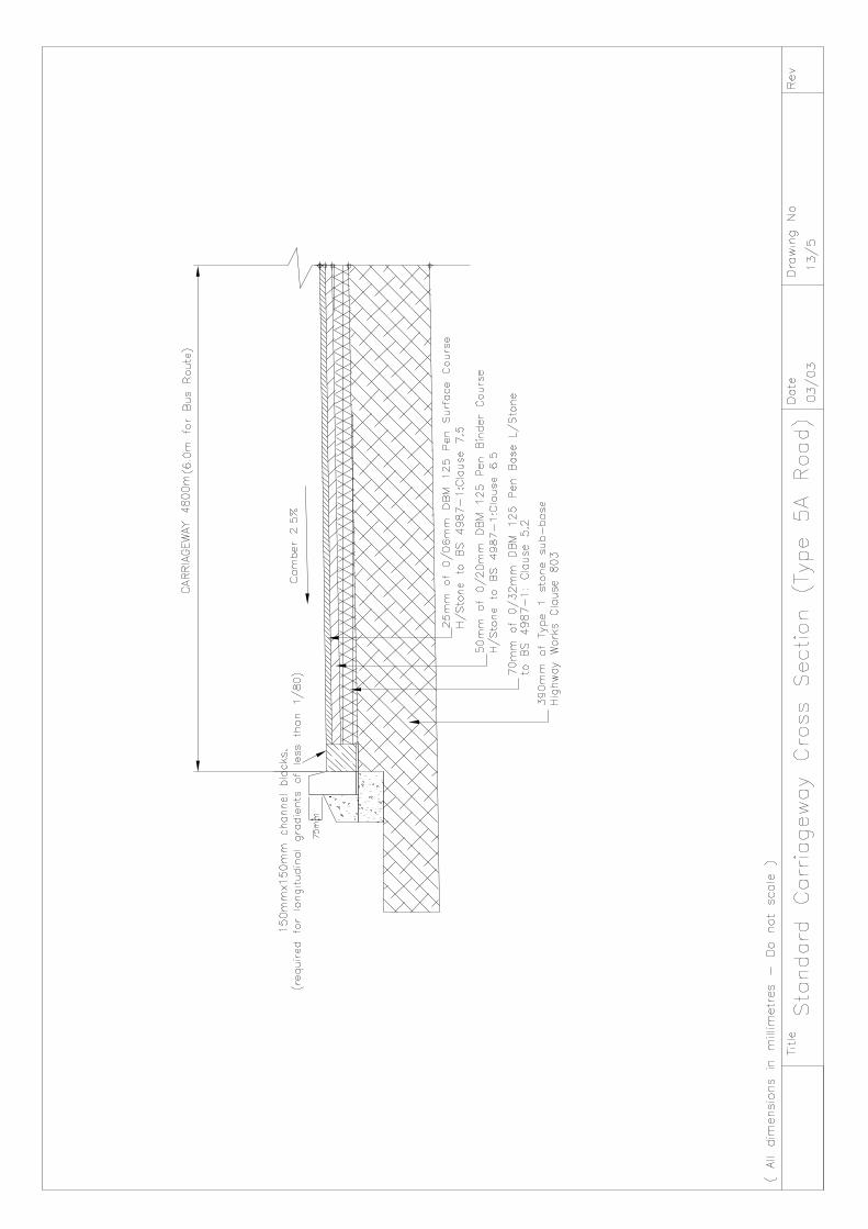
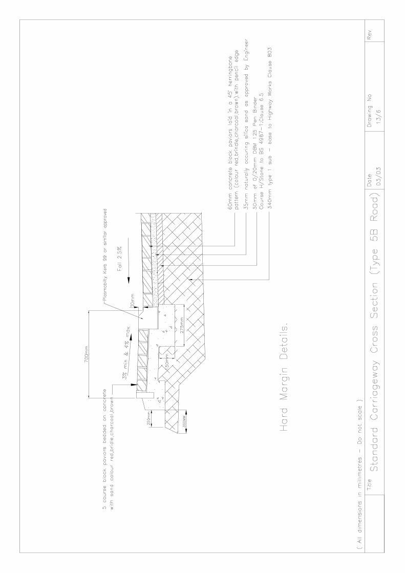
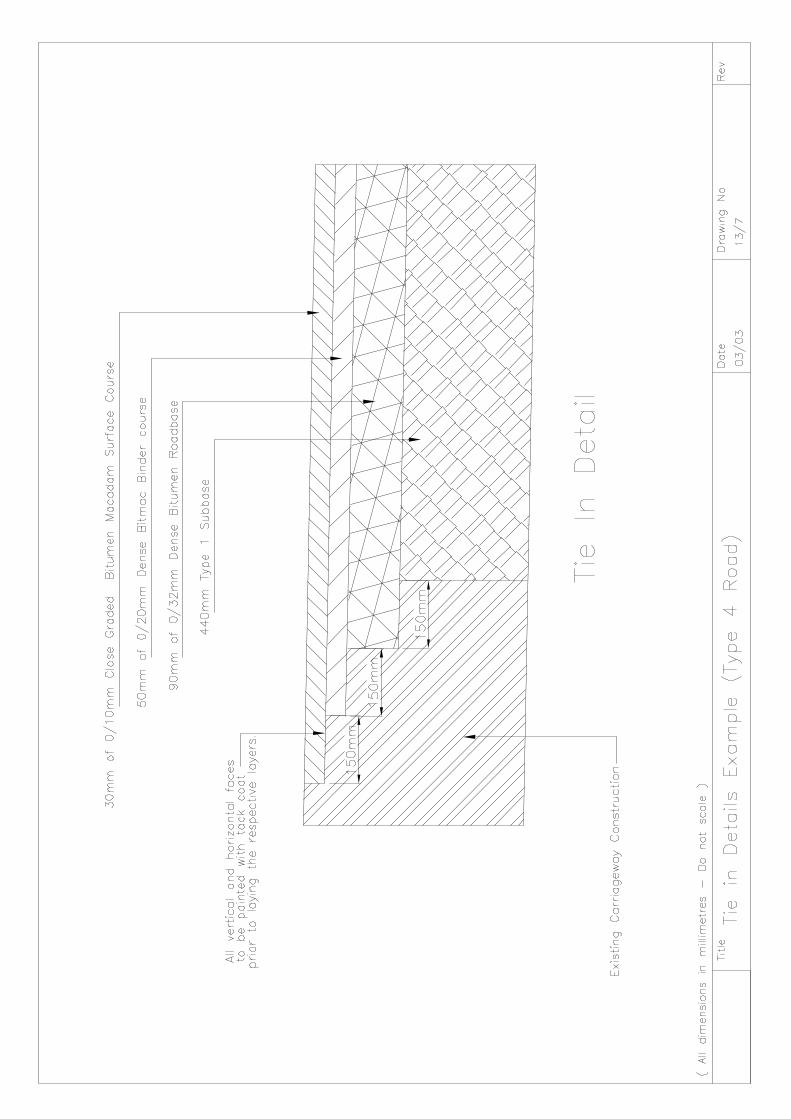
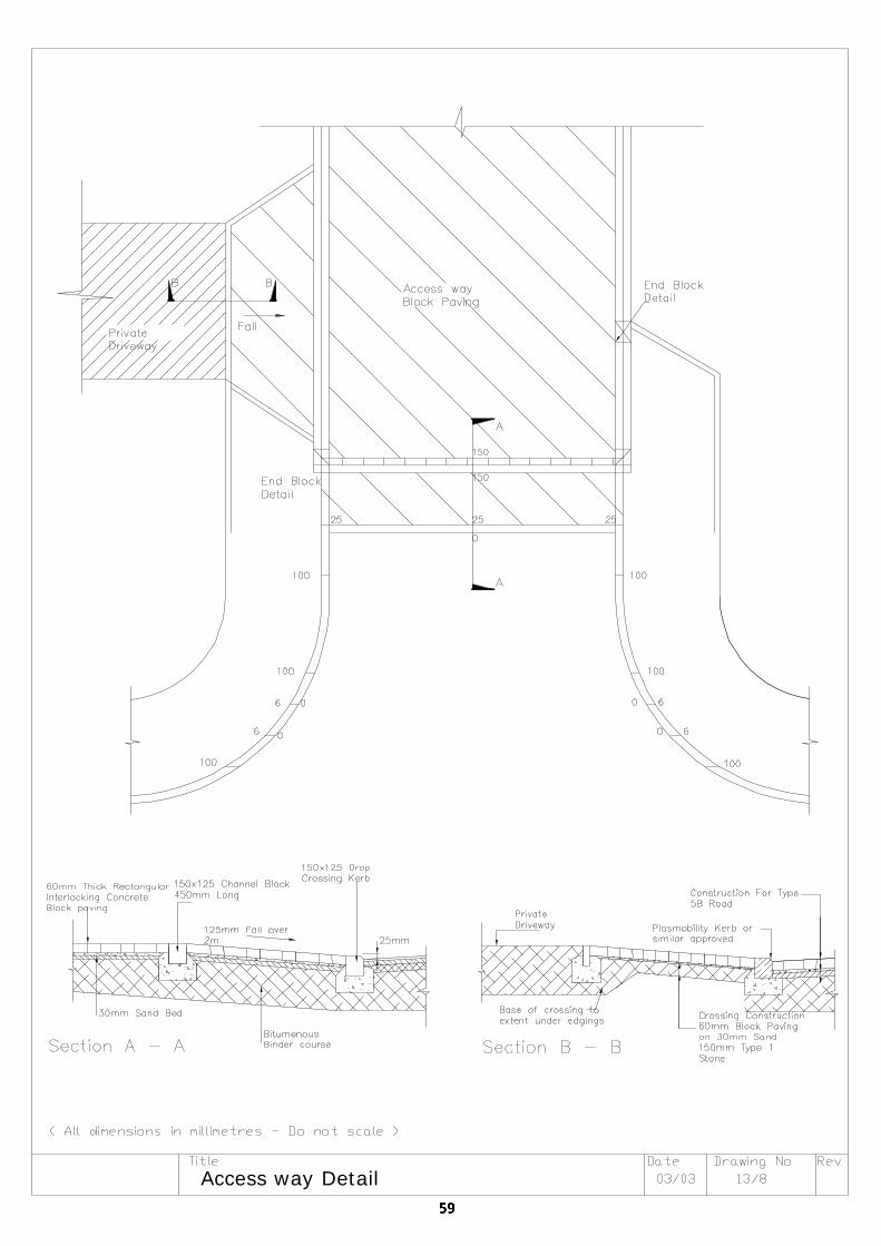
Access way Detail
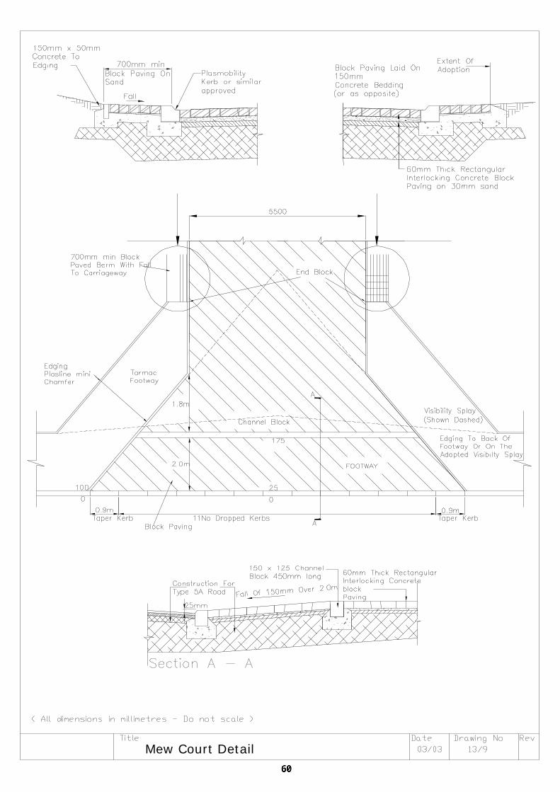
Mew Court Detail
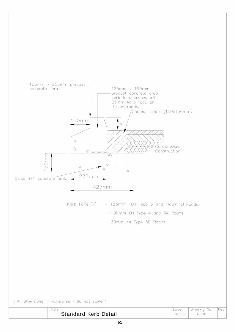
Standard Kerb Detail
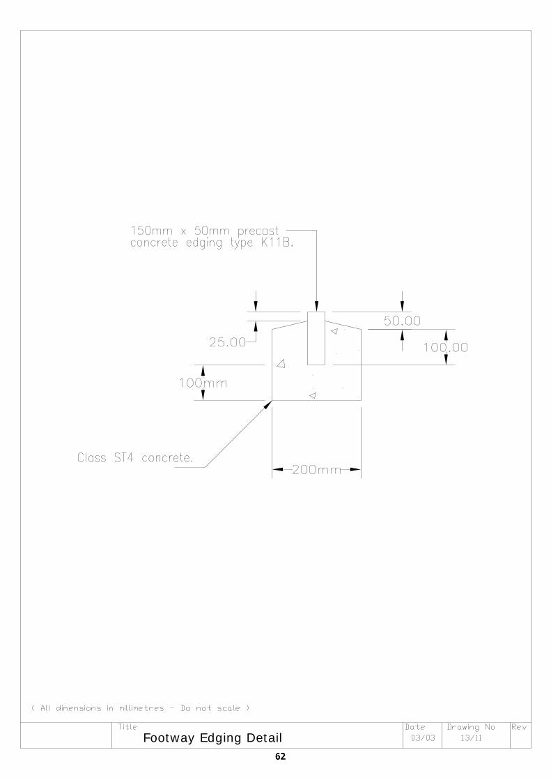
Footway Edging Detail
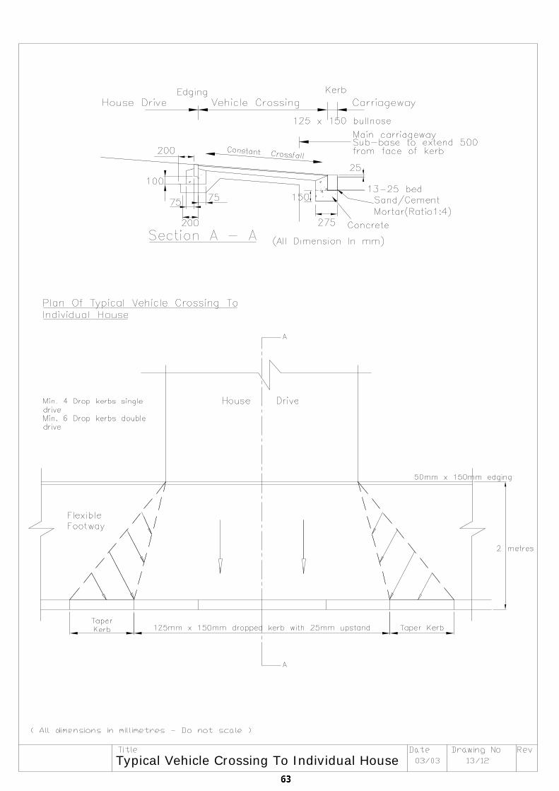
Typical Vehicle Crossing To Individual House
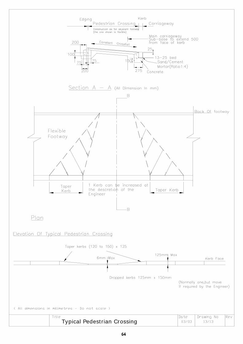
Typical Pedestrian Crossing
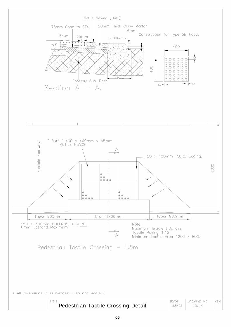
Pedestrian Tactile Crossing Detail
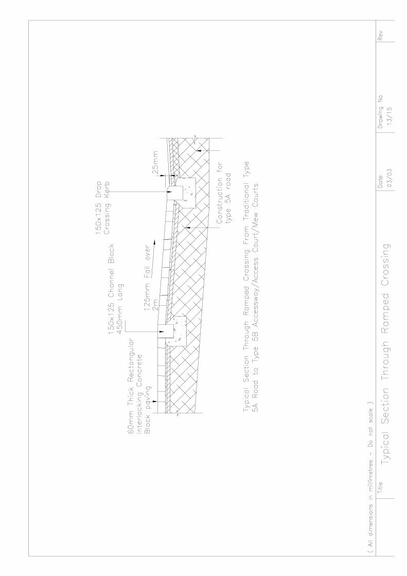
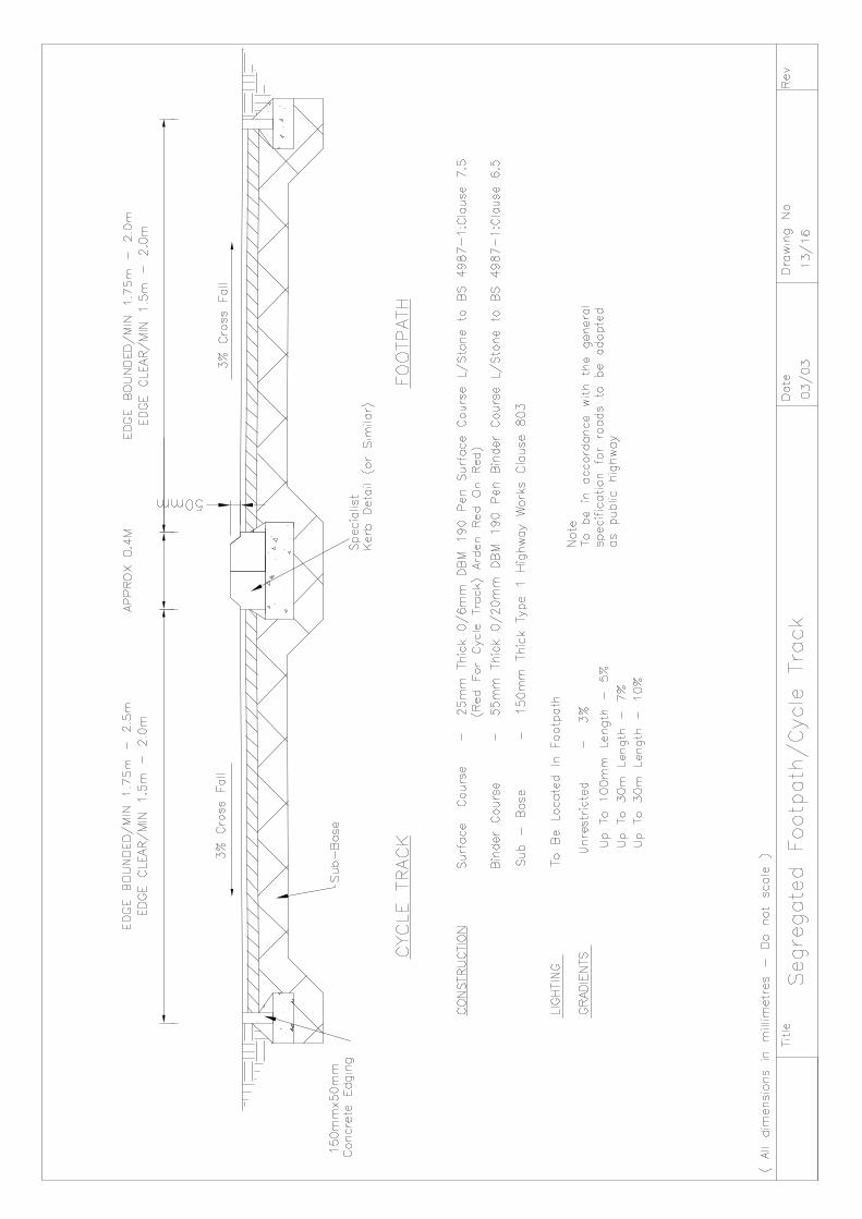
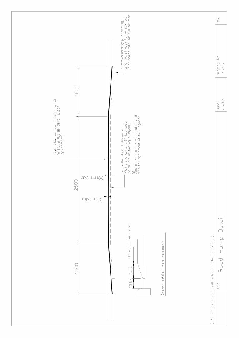
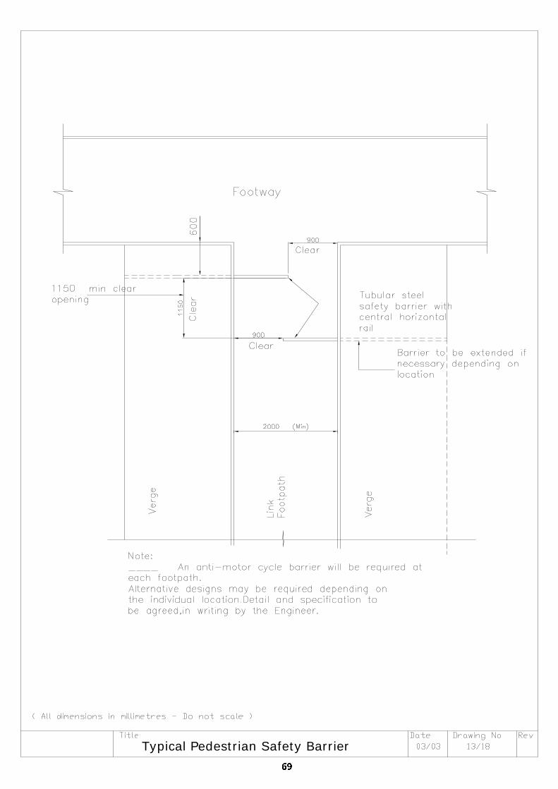
Typical Pedestrian Safety Barrier
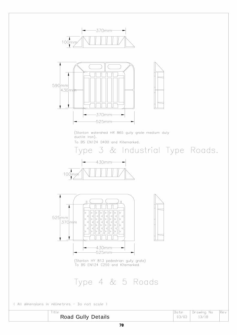
Road Gully Details
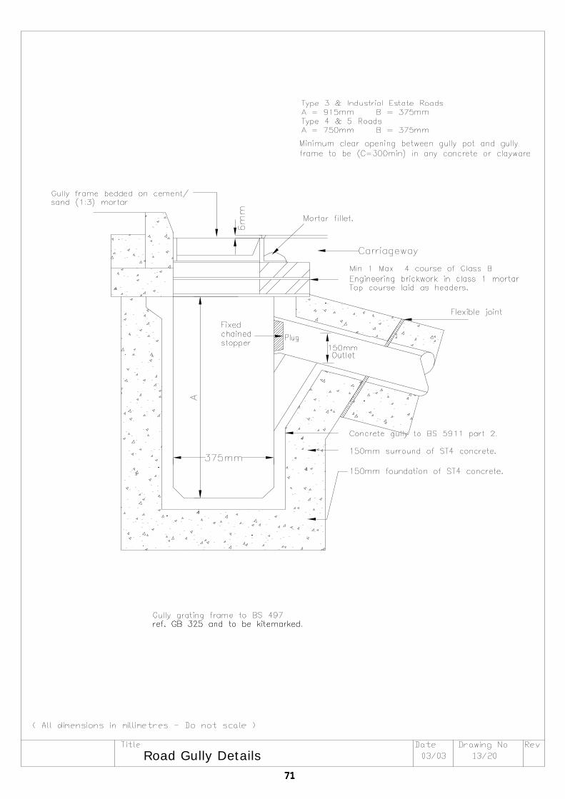
Road Gully Details
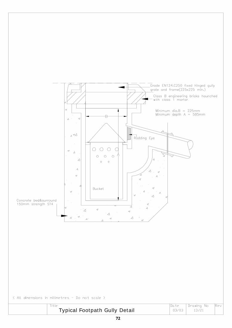
Typical Footpath Gully Detail
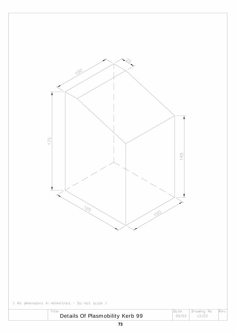
Details Of Plasmobility Kerb 99
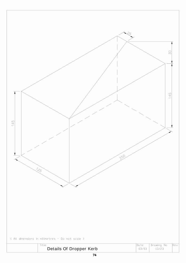
Details Of Dropper Kerb
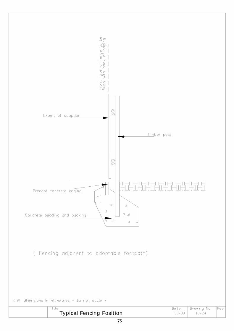
Typical Fencing Position
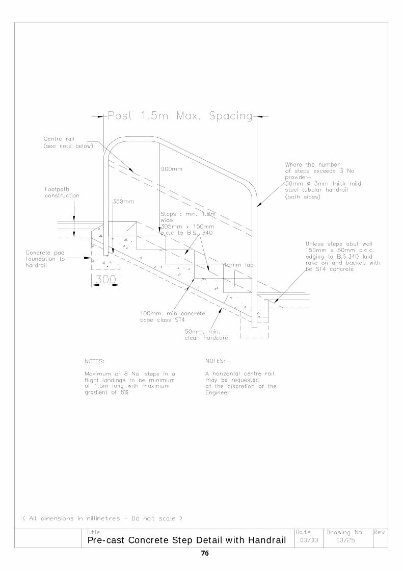
Pre-cast Concrete Step Detail with Handrail
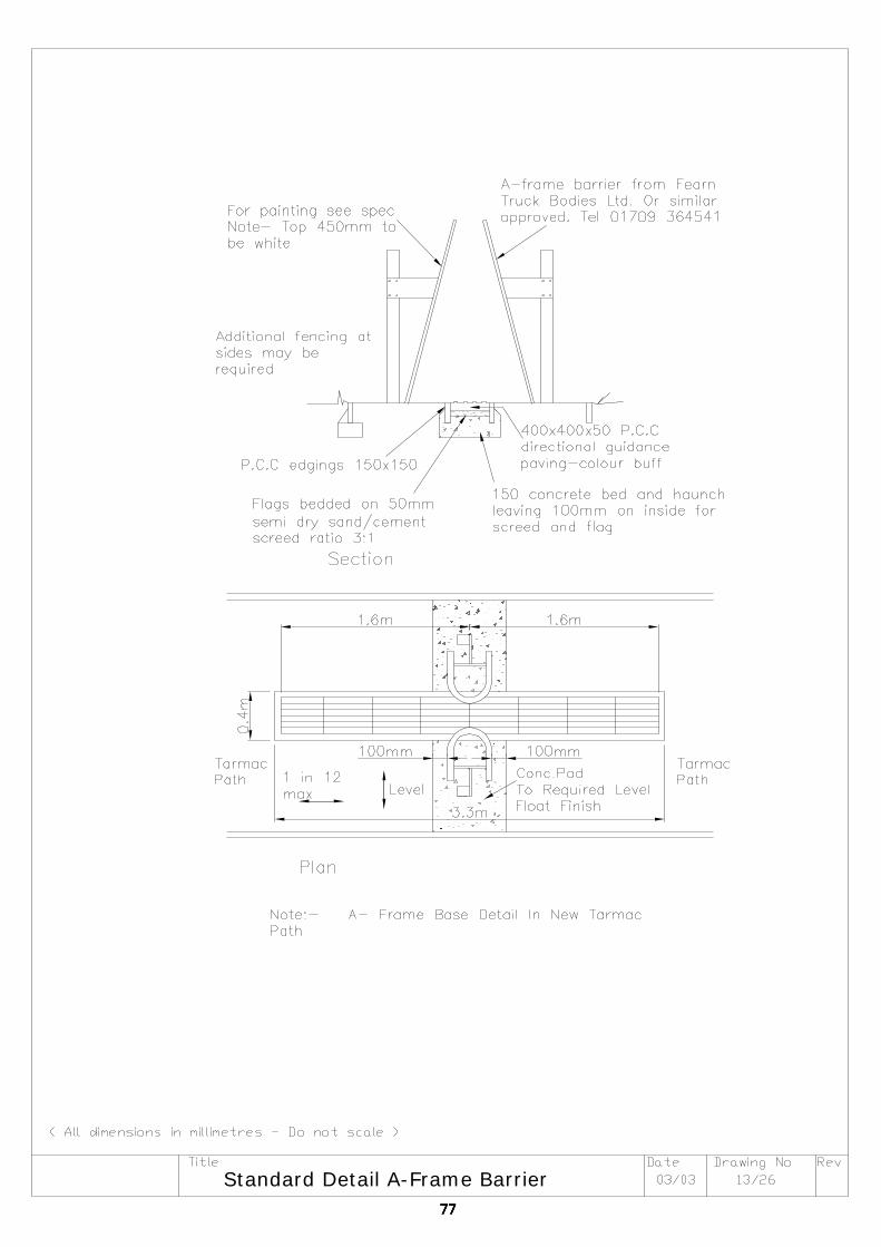
Standard Detail A-Frame Barrier
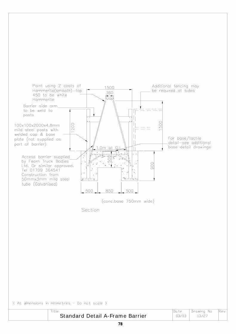
Standard Detail A-Frame Barrier
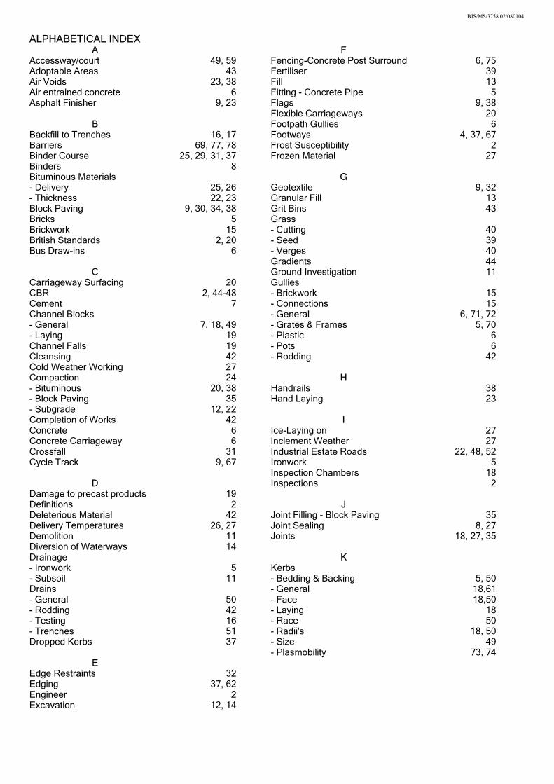
BJS/MS/3758.02/080104
ALPHABETICAL INDEX A F
Accessway/court 49, 59 Fencing-Concrete Post Surround 6, 75Adoptable Areas 43 Fertiliser 39Air Voids 23, 38 Fill 13Air entrained concrete 6 Fitting - Concrete Pipe 5Asphalt Finisher 9, 23 Flags 9, 38 Flexible Carriageways 20
B Footpath Gullies 6Backfill to Trenches 16, 17 Footways 4, 37, 67Barriers 69, 77, 78 Frost Susceptibility 2Binder Course 25, 29, 31, 37 Frozen Material 27Binders 8 Bituminous Materials G - Delivery 25, 26 Geotextile 9, 32- Thickness 22, 23 Granular Fill 13Block Paving 9, 30, 34, 38 Grit Bins 43Bricks 5 Grass Brickwork 15 - Cutting 40British Standards 2, 20 - Seed 39Bus Draw-ins 6 - Verges 40 Gradients 44
C Ground Investigation 11Carriageway Surfacing 20 Gullies CBR 2, 44-48 - Brickwork 15Cement 7 - Connections 15Channel Blocks - General 6, 71, 72- General 7, 18, 49 - Grates & Frames 5, 70- Laying 19 - Plastic 6Channel Falls 19 - Pots 6Cleansing 42 - Rodding 42Cold Weather Working 27 Compaction 24 H - Bituminous 20, 38 Handrails 38- Block Paving 35 Hand Laying 23- Subgrade 12, 22 Completion of Works 42 I Concrete 6 Ice-Laying on 27Concrete Carriageway 6 Inclement Weather 27Crossfall 31 Industrial Estate Roads 22, 48, 52Cycle Track 9, 67 Ironwork 5 Inspection Chambers 18
D Inspections 2Damage to precast products 19 Definitions 2 J Deleterious Material 42 Joint Filling - Block Paving 35Delivery Temperatures 26, 27 Joint Sealing 8, 27Demolition 11 Joints 18, 27, 35Diversion of Waterways 14 Drainage K - Ironwork 5 Kerbs - Subsoil 11 - Bedding & Backing 5, 50Drains - General 18,61- General 50 - Face 18,50- Rodding 42 - Laying 18- Testing 16 - Race 50- Trenches 51 - Radii's 18, 50Dropped Kerbs 37 - Size 49 - Plasmobility 73, 74
E Edge Restraints 32 Edging 37, 62 Engineer 2 Excavation 12, 14
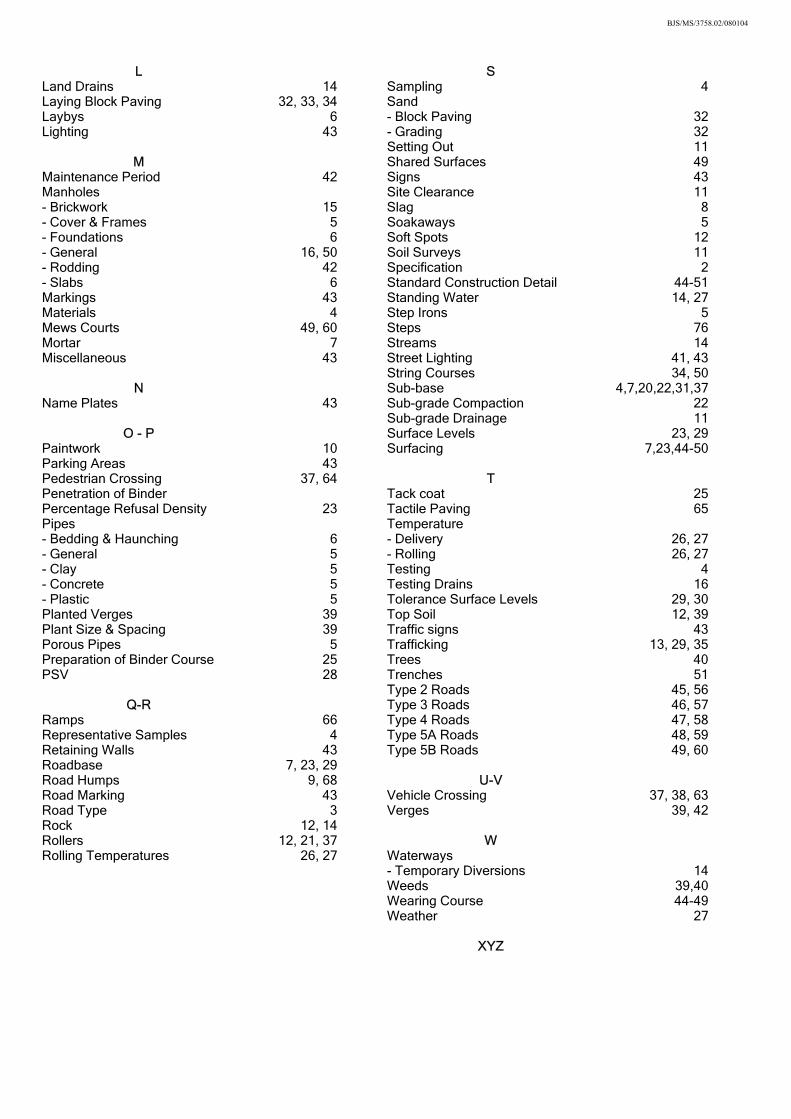
BJS/MS/3758.02/080104
L S
Land Drains 14 Sampling 4Laying Block Paving 32, 33, 34 Sand Laybys 6 - Block Paving 32Lighting 43 - Grading 32 Setting Out 11
M Shared Surfaces 49Maintenance Period 42 Signs 43Manholes Site Clearance 11- Brickwork 15 Slag 8- Cover & Frames 5 Soakaways 5- Foundations 6 Soft Spots 12- General 16, 50 Soil Surveys 11- Rodding 42 Specification 2- Slabs 6 Standard Construction Detail 44-51Markings 43 Standing Water 14, 27Materials 4 Step Irons 5Mews Courts 49, 60 Steps 76Mortar 7 Streams 14Miscellaneous 43 Street Lighting 41, 43 String Courses 34, 50
N Sub-base 4,7,20,22,31,37Name Plates 43 Sub-grade Compaction 22 Sub-grade Drainage 11
O - P Surface Levels 23, 29Paintwork 10 Surfacing 7,23,44-50Parking Areas 43 Pedestrian Crossing 37, 64 T Penetration of Binder Tack coat 25Percentage Refusal Density 23 Tactile Paving 65Pipes Temperature - Bedding & Haunching 6 - Delivery 26, 27- General 5 - Rolling 26, 27- Clay 5 Testing 4- Concrete 5 Testing Drains 16- Plastic 5 Tolerance Surface Levels 29, 30Planted Verges 39 Top Soil 12, 39Plant Size & Spacing 39 Traffic signs 43Porous Pipes 5 Trafficking 13, 29, 35Preparation of Binder Course 25 Trees 40PSV 28 Trenches 51 Type 2 Roads 45, 56
Q-R Type 3 Roads 46, 57Ramps 66 Type 4 Roads 47, 58Representative Samples 4 Type 5A Roads 48, 59Retaining Walls 43 Type 5B Roads 49, 60Roadbase 7, 23, 29 Road Humps 9, 68 U-V Road Marking 43 Vehicle Crossing 37, 38, 63Road Type 3 Verges 39, 42Rock 12, 14 Rollers 12, 21, 37 W Rolling Temperatures 26, 27 Waterways - Temporary Diversions 14 Weeds 39,40 Wearing Course 44-49 Weather 27 XYZ

Useful Contacts Barnsley Metropolitan Borough Council Planning and Transportation Service Central Offices Kendray Street BARNSLEY S70 2TN 01226 772177 www.barnsley.gov.uk Barnsley Development Agency Beevor Court Pontefract Road Barnsley S71 1HG 01226 784444 www.barnsleydevelopmentagency.co.uk Doncaster Metropolitan Borough Council Directorate of Borough Strategy and Development 2nd Floor, Danum House St.Sepulchre Gate Doncaster DN1 1UB 01302 735115 – DC 01302 735114 – S38 www.doncaster.gov.uk Objective One Programme Directorate Silkstone House Pioneer Close Wath-upon-Dearne Rotherham S63 7JZ 01709 763600 www.goyh.gov.uk/objective1 Renaissance South Yorkshire Renaissance House Adwick Park Wath upon Dearne Rotherham S63 5NA 01709 766400 www.surprising-sy.com

Rotherham Metropolitan Borough Council Economic and Development Services Bailey House Rawmarsh Road Rotherham S60 1QT 01709 822965 – DC 01709 822966 – S38 www.rotherham.gov.uk Severn Trent Water Network Development East Leicester water Centre Gorse Hill Leicester LE7 7GU 0116 234 3468 Sheffield City Council Highway Development Control Development Services Sheffield City Council Howden House 1 Union Street Sheffield S1 2SH 0114 273 6368 www.sheffield.gov.uk Sheffield City Council Highway Adoptions Development Services Sheffield City Council Howden House 1 Union Street Sheffield S1 2SH 0114 273 4383 www.sheffield.gov.uk Sheffield One 1 St. James Row Sheffield S1 2EU 0114 203 9090 www.sheffield1.com South Yorkshire Passenger Transport Executive Strategic Planning PO Box 801 Exchange Street Sheffield S2 5YT 0114 221 1340 www.sypte.co.uk

South Yorkshire Police Suite 3 Albion House Saville Street East Sheffield S4 7UQ 0114 220 2020 www.securedbydesign.com Yorkshire Forward Renaissance House Adwick Park Wath upon Dearne Rotherham S63 5NA 01709 766400 www.yorkshire-forward.com Yorkshire Water Sewerage New Development Team Blackburn Meadows STW Alsing Road Sheffield S9 1HX 0845 124 2429

ACKNOWLEDGEMENTS Preparation of this Technical Appendix was funded by South Yorkshire Integrated Transport Group (consisting of SYPTE, Barnsley MBC, Doncaster MBC, Rotherham MBC and Sheffield CC) and prepared by JSM Designs Limited, supported by a Steering Group made up of the following members :- Lucy Mitchell South Yorkshire Passenger Transport Executive Dr A Chymera } } Barnsley Metropolitan Borough Council Barbara Wilson } Mr G Hargraves Doncaster Metropolitan Borough Council Mr J Royston Rotherham Metropolitan Borough Council Mr S Turner } } Sheffield City Council Mr I Wheeldon } Thanks also to Alchemer Presentation Services who provided graphical material


![[4660] - 1 M.E.(Civil) (Construction & Management) (Semester - I](https://img.pdfslide.us/doc/110x75/588db5841a28abb37d8b7324/4660-1-mecivil-construction-management-semester-i-.jpg)