Embed Size (px)
Citation preview
JSC-65829 was subject to two cycles of review by discipline experts from multiple Agency centers as part of its development to support the Commercial Crew Transportation Services Program. Reviews were conducted in April 2010 and over a period spanning July 2010 to December 2010. Reviewers participating and actively providing comments were:
Eli Rayos (JSC-ES611) Bob Ryan (MSFC-HS10)[Will Technology Inc - ASRI] Dave McGhee (MSFC-EV31) Scott West (JSC-ES611) Lee Wilson (JSC-ES611) Vince Fogt (JSC-ES611) George James (JSC-ES611) Rodney Rocha (JSC-ES611) Quyen Jones (JSC-ES611) George Zupp (JSC-EA) [Jacobs Technology] Tom Modlin (JSC-ES2) [Barrios] Isam Yunis (LARC-D206) Scott Gordon (GSFC-5420) Teresa Kinney (KSC-NEO00) Behrouz Pashaee (KSC-NEM50) Jim Broughton (KSC-NEM50) Don Harris (MSFC-ER41) Curt Larsen (JSC-C104) [NESC] Alden Mackey (JSC-EA) [NESC/ATK Space Systems] Ken Hamm (ARC-RE) Tom Irvine (Dynamic Concepts, Inc.) [NESC Technical Discipline Team]
https://ntrs.nasa.gov/search.jsp?R=20110015359 2019-04-10T05:29:30+00:00Z
JSC-65829 Baseline
Loads and Structural Dynamics
Requirements for Spaceflight
Hardware
Loads and Structural Dynamics Branch,
Structural Engineering Division,
Engineering Directorate
January 2011
National Aeronautics and Space Administration Lyndon B. Johnson Space Center Houston, Texas
JSC-65829 Baseline
i
Loads and Structural Dynamics Requirements for Spaceflight Hardware
January 19, 2011
Prepared By:
/s/ Kenneth Schultz K. P. Schultz
Loads and Structural Dynamics Branch Lyndon B. Johnson Space Center
Approved By:
/s/ T. Scott West T. S. West
Branch Chief, Loads and Structural Dynamics Branch Lyndon B. Johnson Space Center
Approved By:
/s/ Edgar O. Castro E. O. Castro
Division Chief, Structural Engineering Division Lyndon B. Johnson Space Center
National Aeronautics and Space Administration Lyndon B. Johnson Space Center
Houston, Texas
JSC-65829 Baseline
ii
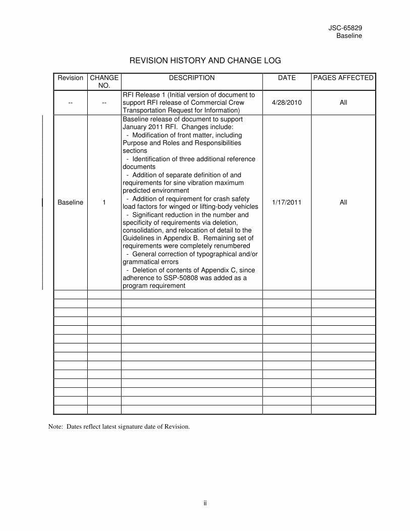
REVISION HISTORY AND CHANGE LOG
Revision CHANGE NO.
DESCRIPTION DATE PAGES AFFECTED
-- -- RFI Release 1 (Initial version of document to support RFI release of Commercial Crew Transportation Request for Information)
4/28/2010 All
Baseline 1
Baseline release of document to support January 2011 RFI. Changes include:
- Modification of front matter, including Purpose and Roles and Responsibilities sections
- Identification of three additional reference documents
- Addition of separate definition of and requirements for sine vibration maximum predicted environment
- Addition of requirement for crash safety load factors for winged or lifting-body vehicles
- Significant reduction in the number and specificity of requirements via deletion, consolidation, and relocation of detail to the Guidelines in Appendix B. Remaining set of requirements were completely renumbered
- General correction of typographical and/or grammatical errors
- Deletion of contents of Appendix C, since adherence to SSP-50808 was added as a program requirement
1/17/2011 All
Note: Dates reflect latest signature date of Revision.

JSC-65829 Baseline
iii
FOREWORD
This document represents the collaborative effort of numerous individuals across many NASA centers. In particular, the experience and expertise of the teams that developed NASA-STD-5002 and the requirements and criteria documents for the Space Shuttle Program, the International Space Station Program, and the Constellation Program was relied on very heavily. Most, if not all, of the technical content in the current document was either adapted from or directly incorporated from those previous documents. The significant efforts expended in developing the Constellation Program Loads Control Plan, CxP-70137, were instrumental to the creation of this document.
JSC-65829 Baseline
iv
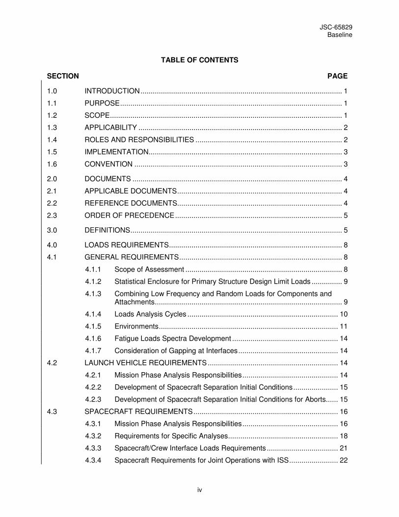
TABLE OF CONTENTS
SECTION PAGE
1.0 INTRODUCTION ................................................................................................... 1
1.1 PURPOSE ............................................................................................................. 1
1.2 SCOPE .................................................................................................................. 1
1.3 APPLICABILITY .................................................................................................... 2
1.4 ROLES AND RESPONSIBILITIES ........................................................................ 2
1.5 IMPLEMENTATION ............................................................................................... 3
1.6 CONVENTION ...................................................................................................... 3
2.0 DOCUMENTS ....................................................................................................... 4
2.1 APPLICABLE DOCUMENTS ................................................................................. 4
2.2 REFERENCE DOCUMENTS ................................................................................. 4
2.3 ORDER OF PRECEDENCE .................................................................................. 5
3.0 DEFINITIONS ........................................................................................................ 5
4.0 LOADS REQUIREMENTS ..................................................................................... 8
4.1 GENERAL REQUIREMENTS ................................................................................ 8
4.1.1 Scope of Assessment ............................................................................. 8
4.1.2 Statistical Enclosure for Primary Structure Design Limit Loads ............... 9
4.1.3 Combining Low Frequency and Random Loads for Components and Attachments ............................................................................................ 9
4.1.4 Loads Analysis Cycles .......................................................................... 10
4.1.5 Environments ........................................................................................ 11
4.1.6 Fatigue Loads Spectra Development .................................................... 14
4.1.7 Consideration of Gapping at Interfaces ................................................. 14
4.2 LAUNCH VEHICLE REQUIREMENTS ................................................................ 14
4.2.1 Mission Phase Analysis Responsibilities ............................................... 14
4.2.2 Development of Spacecraft Separation Initial Conditions ...................... 15
4.2.3 Development of Spacecraft Separation Initial Conditions for Aborts ...... 15
4.3 SPACECRAFT REQUIREMENTS ....................................................................... 16
4.3.1 Mission Phase Analysis Responsibilities ............................................... 16
4.3.2 Requirements for Specific Analyses ...................................................... 18
4.3.3 Spacecraft/Crew Interface Loads Requirements ................................... 21
4.3.4 Spacecraft Requirements for Joint Operations with ISS ........................ 22
JSC-65829 Baseline
v
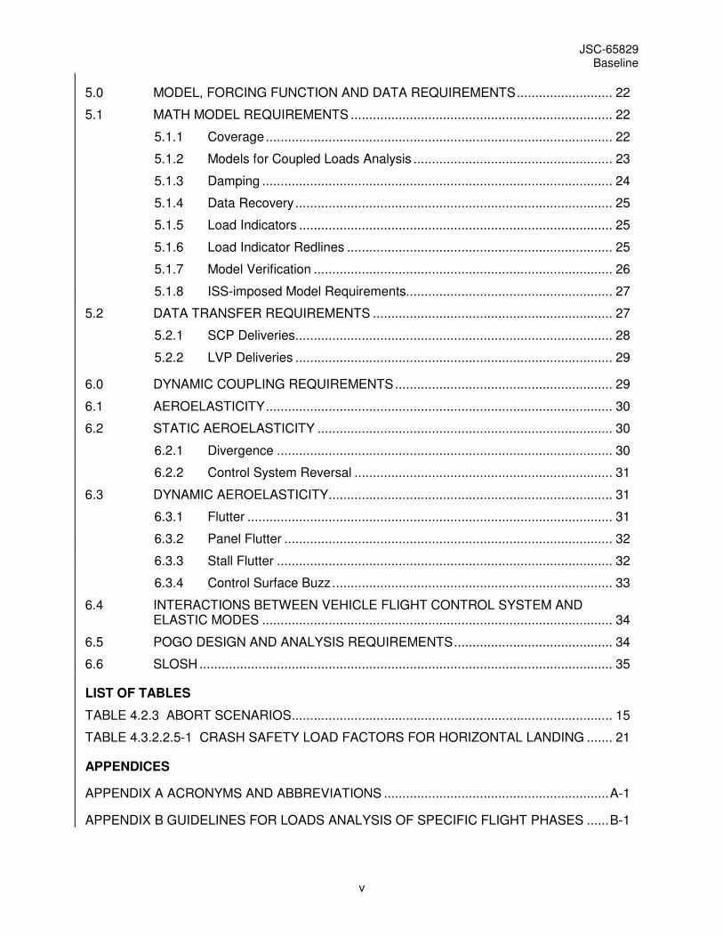
5.0 MODEL, FORCING FUNCTION AND DATA REQUIREMENTS .......................... 22
5.1 MATH MODEL REQUIREMENTS ....................................................................... 22
5.1.1 Coverage .............................................................................................. 22
5.1.2 Models for Coupled Loads Analysis ...................................................... 23
5.1.3 Damping ............................................................................................... 24
5.1.4 Data Recovery ...................................................................................... 25
5.1.5 Load Indicators ..................................................................................... 25
5.1.6 Load Indicator Redlines ........................................................................ 25
5.1.7 Model Verification ................................................................................. 26
5.1.8 ISS-imposed Model Requirements........................................................ 27
5.2 DATA TRANSFER REQUIREMENTS ................................................................. 27
5.2.1 SCP Deliveries ...................................................................................... 28
5.2.2 LVP Deliveries ...................................................................................... 29
6.0 DYNAMIC COUPLING REQUIREMENTS ........................................................... 29
6.1 AEROELASTICITY .............................................................................................. 30
6.2 STATIC AEROELASTICITY ................................................................................ 30
6.2.1 Divergence ........................................................................................... 30
6.2.2 Control System Reversal ...................................................................... 31
6.3 DYNAMIC AEROELASTICITY ............................................................................. 31
6.3.1 Flutter ................................................................................................... 31
6.3.2 Panel Flutter ......................................................................................... 32
6.3.3 Stall Flutter ........................................................................................... 32
6.3.4 Control Surface Buzz ............................................................................ 33
6.4 INTERACTIONS BETWEEN VEHICLE FLIGHT CONTROL SYSTEM AND ELASTIC MODES ............................................................................................... 34
6.5 POGO DESIGN AND ANALYSIS REQUIREMENTS ........................................... 34
6.6 SLOSH ................................................................................................................ 35
LIST OF TABLES
TABLE 4.2.3 ABORT SCENARIOS ....................................................................................... 15
TABLE 4.3.2.2.5-1 CRASH SAFETY LOAD FACTORS FOR HORIZONTAL LANDING ....... 21
APPENDICES
APPENDIX A ACRONYMS AND ABBREVIATIONS ............................................................. A-1
APPENDIX B GUIDELINES FOR LOADS ANALYSIS OF SPECIFIC FLIGHT PHASES ...... B-1

JSC-65829 Baseline
vi
APPENDIX C <DELETED> ................................................................................................... C-1
APPENDIX D MODEL-RELATED REQUIREMENTS FROM THE SPACE STATION LOADS CONTROL PLAN ................................................................................................ D-1
JSC-65829 Baseline
- 1 -
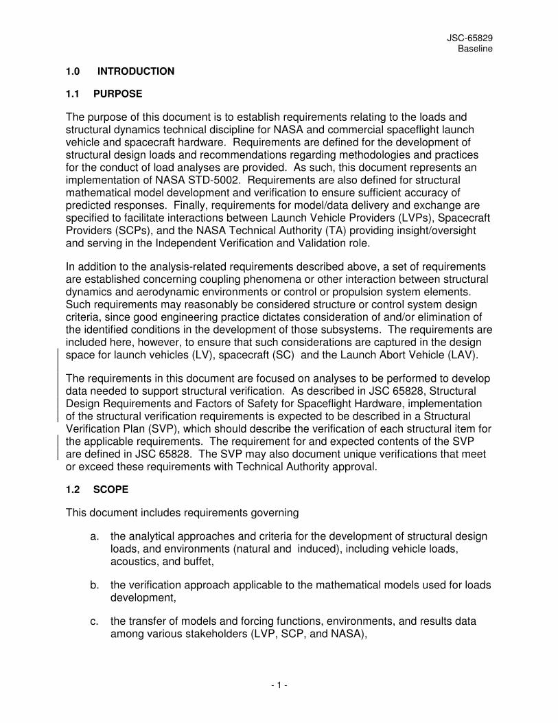
1.0 INTRODUCTION
1.1 PURPOSE
The purpose of this document is to establish requirements relating to the loads and structural dynamics technical discipline for NASA and commercial spaceflight launch vehicle and spacecraft hardware. Requirements are defined for the development of structural design loads and recommendations regarding methodologies and practices for the conduct of load analyses are provided. As such, this document represents an implementation of NASA STD-5002. Requirements are also defined for structural mathematical model development and verification to ensure sufficient accuracy of predicted responses. Finally, requirements for model/data delivery and exchange are specified to facilitate interactions between Launch Vehicle Providers (LVPs), Spacecraft Providers (SCPs), and the NASA Technical Authority (TA) providing insight/oversight and serving in the Independent Verification and Validation role.
In addition to the analysis-related requirements described above, a set of requirements are established concerning coupling phenomena or other interaction between structural dynamics and aerodynamic environments or control or propulsion system elements. Such requirements may reasonably be considered structure or control system design criteria, since good engineering practice dictates consideration of and/or elimination of the identified conditions in the development of those subsystems. The requirements are included here, however, to ensure that such considerations are captured in the design space for launch vehicles (LV), spacecraft (SC) and the Launch Abort Vehicle (LAV).
The requirements in this document are focused on analyses to be performed to develop data needed to support structural verification. As described in JSC 65828, Structural Design Requirements and Factors of Safety for Spaceflight Hardware, implementation of the structural verification requirements is expected to be described in a Structural Verification Plan (SVP), which should describe the verification of each structural item for the applicable requirements. The requirement for and expected contents of the SVP are defined in JSC 65828. The SVP may also document unique verifications that meet or exceed these requirements with Technical Authority approval.
1.2 SCOPE
This document includes requirements governing
a. the analytical approaches and criteria for the development of structural design loads, and environments (natural and induced), including vehicle loads, acoustics, and buffet,
b. the verification approach applicable to the mathematical models used for loads development,
c. the transfer of models and forcing functions, environments, and results data among various stakeholders (LVP, SCP, and NASA),
JSC-65829 Baseline
- 2 -
d. the roles and responsibilities for loads development, including general task descriptions and input and output requirements, and
e. the considerations of phenomena associated with the interaction of system structural dynamics and environments and vehicle subsystems.
This document is intended to cover analyses representing all phases of a spaceflight vehicle mission profile, including pre-flight, post-flight, and abort activities. The requirements herein represent the minimum set of conditions necessary to ensure proper identification of bounding loads and loading conditions and, in turn, contribute to a structural design solution which is adequate to maintain structural integrity and the required degree of functionality during all phases of the expected life cycle.
1.3 APPLICABILITY
This document establishes requirements for the loads and dynamics technical discipline and provides guidelines and good design practices identified by the NASA loads and dynamics technical community. It is applicable to both NASA and commercial launch vehicles and spacecraft. This document contains requirements that LVPs and SCPs can choose to either adopt as written or propose an alternate. LVPs and SCPs are allowed to propose alternate requirements and standards that they consider to meet or exceed the requirements listed herein.
The NASA Program under which the launch vehicle and/or spacecraft is developed will charter a Loads and Structures Panel (LSP) for reviewing and approving the implementation of the requirements of this document. The LSP will serve as the responsible Technical Authority for structural design limit loads and environments. The Technical Authority will evaluate the equivalency of any alternate requirements proposed by the LVPs and SCPs. It will be the responsibility of the LVP and/or SCP to demonstrate to the NASA TA that a proposed alternate requirement fully meets the intent of the requirements of this document and to obtain formal NASA approval of the alternate requirement(s). When consensus cannot be reached on the resolution of an issue, the TA will bring forward the issue with a recommendation to the appropriate Program Board, along with the organizational team members presenting their conflicting positions.
1.4 ROLES AND RESPONSIBILITIES
Depending on mission phase, responsibility for performing loads analysis may fall to either the LVP, the SCP, or both. For example, if the LVP is responsible for ascent atmospheric flight analyses, the LVP will require structural dynamic math models from the SCP to complete the analysis, while resulting induced aeroacoustic and vibration environments and LV/SC interface load states will be required by the SCP to perform detailed assessment of the responses of SC internal components. In such cases, timely transfer of model, forcing function, and environment data is crucial to continued progress of design efforts. Note that the possibility exists that the LVP and the SCP are the same commercial entity.
JSC-65829 Baseline
- 3 -
It is expected that the NASA TA will maintain a significant technical insight/oversight responsibility and IV&V role consistent with the procedures established for launch vehicles by NPD 8610.23. Launch vehicles with varying degrees of flight history may be considered to fill the LV role for NASA-acquired or NASA-developed crew launch services. NPD 8610.7 establishes an effective framework for identifying the appropriate level of NASA involvement, consistent with LV flight history and operational maturity. For existing LV, however, modifications may be necessary to accommodate newly-developed spacecraft. Under the NPD 8610.7 framework, negotiations will be required to determine whether such modifications will be significant enough to be classified as configuration changes or if they may be classified simply as upgrades. This is an important consideration as configuration changes drive a requirement for re-certification of the LV, along with a greatly increased NASA role in the process. Regardless of policy-level certification or classification, flight vehicle outer mold line and internal structural modifications will result in changes to vehicle structural dynamics and induced loads and dynamics. Significant loads and dynamics analyses will, therefore, be required, with correspondingly significant TA involvement.
Although no NASA policy framework currently exists which applies to commercial crew transportation spacecraft, NPD 8610.7 and 8610.23 appear to provide a good benchmark for guiding the interaction between NASA and the SCP. However, since newly-developed SC, by definition, have no flight history, it is anticipated that the NASA TA will work closely with the SCP.
In all instances, however, the NASA TA will retain a sufficient level of insight and oversight to substantiate the accuracy and adequacy of the results of any loads analysis performed under Program governing development and operation of the LV and/or SC.
1.5 IMPLEMENTATION
The convention used in this document to distinguish between requirements and goals is as follows: “shall” is used to indicate requirements that must be implemented and verified, and “should” is used to indicate goals that must be addressed but do not need to be verified. “Shall” requirements are contained within relevant subsections and indicated with a unique number using the format [LDxxxx] for easier traceability. Requirement statements explicitly state whether the requirement is applicable to the LV or the SC. The phrase "Flight Vehicle providers" or "Flight Vehicles" in a requirement statement indicates that the requirement is applicable to both the LV and the SC.
The purpose of the Rationale statements is to indicate why each particular requirement is needed, to describe the basis for its inclusion in this requirements document, and to provide context and examples to stakeholders. It is important to note that the rationales are not binding and only provide supporting information.
1.6 CONVENTION
This document designates undetermined values of quantities as To Be Resolved (TBR) or To Be Determined (TBD). Where approximate values of such quantities are known
JSC-65829 Baseline
- 4 -
and provide useful guides for development, these values are shown along with a TBR notation. Where no value is yet known, a TBD is included.
2.0 DOCUMENTS
2.1 APPLICABLE DOCUMENTS
The following documents include specifications, models, standards, guidelines, handbooks, and other special publications. The documents listed in this paragraph are applicable to the extent specified herein.
JSC 65828 Baseline Structural Design Requirements and Factors of Safety for Spaceflight Hardware
2.2 REFERENCE DOCUMENTS
The following documents contain supplemental information to aid the user in the understanding and application of this document.
NPD 8510.23 Revision C NASA Policy Directive: Launch Vehicle Technical Oversight Policy
NPD 8610.7 Revision D NASA Policy Directive: Launch Services Risk
Mitigation Policy for NASA-Owned and/or NASA-Sponsored Payloads/Missions
NASA-STD-5002 Baseline Load Analyses of Spacecraft and Payloads
NASA-HDBK-7005 Baseline Dynamic Environmental Criteria
MSFC-RQMT-3019 Baseline Launch Vehicle Qualification Requirements
D684-10019–1 Baseline Space Station Structural Loads Control Plan (Boeing Document)
NASA-TM-X-73305 Baseline Astronautic Structures Manual, volume 1
ELVL-2001-0002834 Revision A Guidance on the Number of Coupled Loads
Analysis Cycles Required for a NASA ELV Mission (Rev A)
NASA SP-8003 Baseline Flutter, Buzz and Divergence
NACA TN-3030 Baseline A Method for Calculating the Subsonic Steady-
state Loading on an Airplane with a Wing of Arbitrary Plan Form and Stiffness
NASA SP-8004 Revised, June 1972 Panel Flutter
JSC-65829 Baseline
- 5 -
NASA SP-8055 Baseline Prevention of Coupled Structure-Propulsion Instability (Pogo)
NASA SP-8072 Baseline Acoustic Loads Generated by the Propulsion System
NASA SP-8077 Baseline Transportation and Handling Loads
NASA-SP-8099 Baseline Combining Ascent Loads
2.3 ORDER OF PRECEDENCE
In the case of conflict, where this document is adopted or imposed by contract on a program or project, the technical guidelines of this document take precedence over the technical guidelines cited in other referenced documents.
3.0 DEFINITIONS
For the purposes of this document, the following definitions shall apply:
Abort: A launch phase process to protect and extract the crew from a failing launch vehicle and get them safely to the surface of the Earth or to orbit.
Blast Overpressure: The airborne shock wave or acoustic transient generated by an explosion.
Blast Debris: The debris field generated by an explosion, where debris is defined as any external broken and/or scattered remains emanating from the element(s) of any flight or ground systems.
Buzz: A control-surface phenomenon; a type of flutter including only one degree of freedom. Buzz is usually a pure rotational oscillation of a control surface, but may appear as a torsional "windup" oscillation if the surface is restrained near one end. It generally occurs in regions of transonic flow.
Component: An equipment item that is part of a spacecraft and is treated as an entity for purposes of load analysis (examples are electronic boxes, batteries, electromechanical devices, and scientific instruments or experiments).
Divergence: A nonoscillatory instability which occurs when the external aerodynamic upsetting moments exceed the internal structural restoring moments within a system.
Factor of Safety (FOS): A multiplying factor to be applied to limit loads or stresses for purposes of analytical assessment (design factors) or test verification (test factors) of design adequacy in strength or stability. Factors of safety are empirically based and are necessary to assure no failures due to uncertainties that result from the design process, manufacturing process, and the loading environment.

JSC-65829 Baseline
- 6 -
Fatigue Equivalent Duration: The length of time at the maximum environment achieved during the service life that produces the same fatigue damage potential as application of all time-varying acoustic or vibration environments that make up the full service life.
Flight Vehicle: The combination of elements of the launch system that is flown to orbit (e.g., the launch vehicle and the spacecraft).
Flutter: A self-excited oscillation caused and maintained by the aerodynamic, inertia, and elastic forces in the structural system of a vehicle.
Launch Abort Vehicle (LAV): The specific vehicle configuration that is used to fly the crew to safety in the event of an abort.
Launch Vehicle (LV): One or more of the stages of a flight vehicle capable of launching a spacecraft into a suborbital or orbital trajectory. Upper-stages used to inject a spacecraft into orbit from a suborbital trajectory and fairings used to protect the spacecraft during ascent, unless provided by the spacecraft, are considered part of the launch vehicle for the purposes of this requirements document.
Limit Load: The maximum load or combination of loads which a vehicle or its structural elements may be expected to encounter during its design service life. Uncertainty factors associated with model uncertainty or forcing function uncertainty may be incorporated into the limit load as reported. Factors of safety are not included in the limit load.
Load Indicator: An approximate definition of the state of load or stress within a critical vehicle element structural substructure or part that can be evaluated directly at the external loads level of analysis. Although some indicators can exactly replicate the state of stress in a part if the loading and structural capability is simple, most load indicators are approximations. To be "evaluated directly at the external loads level" means that all inputs to the indicator are available in external loads databases, which are normally coarser approximations of loads than are used during the element stress evaluation. It should be noted that different load regimes (e.g., liftoff and maximum dynamic pressure) have different critical load paths and structures and, therefore, require different load indicators. Load indicators are valid only for the conditions used in developing the equations which define the load indicator.
Maximum Predicted Environment (MPE): The environment for random vibration, acoustics, and shock defined using a P95/50 normal tolerance limit, which is the level greater than 95% of the peak events with 50% statistical confidence or the environment for sine vibration defined using a P97.72 normal tolerance limit, which is the level greater than 97.72% of the peak events with 50% statistical confidence.
Pogo: An instability resulting from the coupling between the rocket engine thrust and the vehicle structural dynamics. This coupling will cause the continuous increase in the magnitude of the engine thrust oscillations and propellant flow rate oscillation, which manifests itself as an instability.

JSC-65829 Baseline
- 7 -
Primary Structure: (See Structure, Primary)
Random Vibration: The non-deterministic oscillatory response of a structure caused by acoustical and/or mechanical forcing functions. The magnitude and spectral content of random vibration is known only in terms of statistical average properties.
Redlines: Limits provided for load indicators or other vehicle element responses, primarily based on certification experience, used to determine the adequacy of the structure under the action of a particular load condition. Redlines represent the maximum allowable design load, whether or not there is additional margin in the structure that the load indicator or element response represents.
Secondary Structure: (See Structure, Secondary)
Spacecraft (SC): A self-contained vehicle or system that is developed to operate in space. A spacecraft consists of a support structure onto which are attached scientific instruments and related systems for communication, power, propulsion, life support, and control.
Structure: All components or assemblies designed to sustain loads or pressures, provide stiffness and stability, or provide support or containment.
Structure, Primary: That part of a flight vehicle or element which sustains the significant applied loads and provides main load paths for distributing reactions to applied loads. Also the main structure which is required to sustain the significant applied loads, including pressure and thermal loads, and which if it fails creates a catastrophic hazard. If a component is small enough and in an environment where no serious threat is imposed if it breaks, then it is not primary structure.
Structure, Secondary: Ancillary or auxiliary internal or external structure which is used to attach small components, provide storage, and to make either an internal volume or external surface usable. Secondary structure attaches to and is supported by primary structure.
Twang: The loads induce on the LAV at separation from the LV while in unusual flight attitudes, with off-nominal bending, and under the influence of separation mechanism loads. The sudden release of stored elastic strain energy due to bending under these conditions results in a near-instantaneous step change in shear and bending loads at the LV to LAV interface. A similar twang effect occurs during liftoff.
Uncertainty Factory (UF): A value used to compensate for a deficiency in knowledge concerning the accuracy of analytical or test results. Such factors are used as a management tool, in a manner similar to weight growth margins, to manage the loads growth uncertainty and to ensure a robust design.
JSC-65829 Baseline
- 8 -
4.0 LOADS REQUIREMENTS
4.1 GENERAL REQUIREMENTS
This section defines overarching requirements applicable to both the LV and the SC. Where analytical or other responsibilities lie with either one organization or the other, appropriate requirements are defined in subsequent sections specific to the LV or the SC.
4.1.1 Scope of Assessment
[LD0001] Flight Vehicle providers shall assess all anticipated static and dynamic loading events over all phases of their expected vehicle life cycles to establish limit loads.
Rationale: Complete coverage of the mission profile is necessary to ensure that bounding load cases are identified. Spaceflight hardware must be designed to ensure adequate structural strength under all static and dynamic load environments and combinations of loads that are expected to occur during all phases of fabrication, testing, transportation, assembly, erection, checkout, launch, ascent, in-space operations, atmospheric entry, descent, landing, and recovery (if applicable). Appendix B provides guidelines for considerations in and recommended approaches to the assessment of key events over typical flight vehicle life cycles.
[LD0002] Flight Vehicle providers shall evaluate each source of loading within each mission phase and the different load sources that can occur simultaneously shall be combined in a rational manner.
Rationale: In cases where loads produced by different environments can occur simultaneously, these loads must be combined in a rational manner to define the limit load for that flight event. Types of load combinations vary dependent upon the particular launch vehicle. For the Shuttle, common types of load combinations are transient loads with random vibration loads due to liftoff events and transient loads with thermally induced loads due to landing. For some expendable launch vehicles (ELV’s), the transient loads and the random vibration loads due to liftoff do not occur simultaneously and are not combined. Loads due to pressurization of pressure vessels, venting, and installation misalignments should be included.
[LD0003] Flight Vehicle providers shall identify load conditions for each configuration of structure that will have multiple configurations during a mission.
Rationale: Maximum loads for deployable or on-orbit configurable hardware may not be caused by flight events while the hardware is in its stowed configuration. Evaluation of hardware in all of its deployed or operating configurations is vital to ensure proper identification of the bounding load cases.

JSC-65829 Baseline
- 9 -
[LD0004] Flight Vehicle providers shall include system dispersions in analysis performed to develop design limit loads.
Rationale: Possible dispersions in environments, vehicle performance, forcing functions, etc. must be accounted for in order to ensure capture of bounding load cases. Confidence in limit load predictions can only be achieved by identifying and considering variability in all input conditions which can affect vehicle responses. Appendix B provides guidelines for dispersions which should be included in the assessment of key events over typical flight vehicle life cycles.
4.1.2 Statistical Enclosure for Primary Structure Design Limit Loads
[LD0005] Limit loads for primary structure of Flight Vehicles shall be determined which encompass at least a 0.9987 probability of no exceedance, with 50-percent confidence.
Rationale: Design loads must be established at levels which envelope flight experience and minimize the likelihood of experiencing higher loads during operation of the vehicle, while simultaneously avoiding overconservatism which may preclude achieving a design which will close and still meet performance requirements. The so-called “3-sigma” probability of .9987 with 50-percent confidence is traditionally used for aerospace structure.
Note that some structures will be subjected to static, quasi-static, acoustic, sinusoidal, transient, and random vibration loads. When loads produced by different environments or flight events can occur simultaneously, these loads must be combined, as applicable, in a rational manner to define the limit load for that flight, before using them in a strength or life assessment. Common types of load combinations include static pressure loading occurring at the same time as turbulent buffeting during atmospheric entry and thermal loads occurring at the same time as deployment release loads and/or end of travel loads. Input values/ranges of parameters for loads analyses should be defined that produce loads that statistically meet the defined probability levels. Recommended guidelines for performing this type of load combination are found in Appendix B.
4.1.3 Combining Low Frequency and Random Loads for Components and Attachments
[LD0006] Quasi-static loads, low frequency transient loads and random vibro-acoustic loads for Flight Vehicle components shall be combined in a rational manner to determine the total loads environment for components of flight vehicle systems. Combined loads for components shall encompass at least a .9987 probability of no exceedance, with 50-percent confidence, in each of three orthogonal axes. Off-axis components of the combined load which are applied simultaneously may have less statistical enclosure.
Rationale: The total load environment experienced by components mounted on or within Flight Vehicles is the resultant of contributions from several loading sources. In addition to the quasi-static inertial loading due to vehicle acceleration

JSC-65829 Baseline
- 10 -
in response to thrust loads and other steady forces, three basic types of flight environments generate dynamic loads on Flight Vehicle components and component attachments:
a. Low-frequency dynamic response, typically from 0 to 50 Hertz (Hz), of the LV/SC system to transient flight events.
b. High-frequency random vibration environment, which typically has significant energy in the frequency range from 20 Hz to 2000 Hz, transmitted from the launch vehicle to the SC at the LV/SC interfaces.
c. High frequency acoustic pressure environment, typically 31 Hz to 10,000 Hz, inside the LV or SC compartment. The payload compartment acoustic pressure environment generates dynamic loads on components in two ways: (1) by direct impingement on the surfaces of exposed components, and (2) by the acoustic pressure impingement upon the component mounting structures, which induces random vibrations that are mechanically transmitted to the components.
Combinations of these loads occur at different times in flight and shall be examined for each flight event. For components weighing less than 500 kg, the appropriate method of load combination is dependent on how the low frequency and the random vibration/acoustic design environments of the event are specified. Typically, the maximum levels are defined as requirements for a flight event, such as liftoff, even if these maxima do not necessarily occur at the same time. The relative timing of the transient and random vibration environments is unique for each launch vehicle, but simultaneous occurrence of maximum low frequency transient and maximum random vibration load is improbable. Therefore, an RSS approach is acceptable for combining the maximum low frequency and maximum random vibration loads for the liftoff flight event. When the low frequency transient and random vibration environments are specified in a time correlated manner, a time consistent approach is also acceptable for combining the low frequency transient loads and the random vibration loads.
Appendix B contains one recommended technique for developing combined loading environments for flight vehicle components.
4.1.4 Loads Analysis Cycles
[LD0007] Flight Vehicle providers shall perform a minimum of two load cycles: a preliminary design cycle and a verification cycle.
Rationale: Estimation of loads for flight vehicles is an iterative process. Preliminary design loads are used for the initial sizing of structure; then a mathematical model of the structure is developed and a preliminary load cycle is performed. Based on the resulting loads, structural sizing may need to be adjusted. The effect of design change due to loads or possibly to configuration changes can alter the static and dynamic properties of the structure, thereby changing the loads. Subsequent load cycles are needed to assess the changes
JSC-65829 Baseline
- 11 -
in design, in launch vehicle and payload mathematical models, and in forcing functions. It is expected that more than two load analysis cycles will be necessary for Flight Vehicle design to fully converge. Some useful guidance on appropriately scoping the number of load cycles needed may be found in technical memorandum ELVL-2001-0002834.
[LD0008] Flight Vehicle providers shall use verified math models, environments, and forcing functions when performing the verification loads analysis cycle. Models may be verified in any combination of test and analysis which meets uncertainty requirements.
Rationale: The verification loads analysis cycle is so called because all models should be verified and therefore provides results that can be trusted as reliable. Similarly, forcing functions and environments used in the verification cycle should be anchored to test data and/or flight experience. The verification loads analysis cycle is used to confirm that positive spacecraft and launch vehicle margins exist for all load events. Displacement output from the analysis is also used by the launch vehicle organization for the loss of clearance analysis. The modes of vibration from the load cycle structural models are also used by the launch vehicle organization in the controls analysis.
Verification by analysis is more appropriate for models of forcing functions and environments for vehicles with significant flight history and less so for new vehicles/spacecraft with little or no flight experience. Structural dynamics math models should be verified by test.
The term "models" encompasses more than the structural dynamic math models used for coupled loads analysis. There are engine thrust models - build up, steady burn, and shut down. There are aerodynamic models, total vehicle coefficients, running load distributions, and pressure distributions. There are wind models of both ground winds and ascent winds.
4.1.5 Environments
4.1.5.1 Program-Specified Environment Data
[LD0009] Flight Vehicle providers shall incorporate the natural environments defined in the Program-specified documentation in loads and dynamics analyses for all relevant mission phases.
Rationale: Note: This is a placeholder requirement for TBD LV or SC development Program.
Natural environments (atmospheric and ground winds, density and pressure as a function of altitude, sea states, etc.) exert significant influence on loads for certain events in the mission profiles of flight vehicles. Development of accurate design loads and environments requires inclusion of well-defined and correct representations of any natural environments which may affect analysis results.
JSC-65829 Baseline
- 12 -
Appendix B provides information and guidelines on including the effects of natural environments in the analysis of various mission phases and events.
4.1.5.2 Maximum Predicted Environment (MPE)
[LD0010] MPE for Flight Vehicle random vibration, acoustic, and shock environments shall be defined using a P95/50 normal tolerance limit based on:
a. The use of actual flight data scaled, if necessary, for differences in structure and acoustic environment and/or
b. Ground test data scaled if necessary and/or
c. Analytical predictions
Rationale: The P95/50 normal tolerance limit is the level enveloping greater than 95% of the peak events with 50% statistical confidence. This statistical coverage is standard NASA and industry practice, balancing the need for definition of an environment with a low probability of exceedance with the inherent limitations on allowable conservatism in optimized aerospace structures.
[LD0011] MPE for Flight Vehicle sine vibration environments shall be defined using a P97.72/50 normal tolerance limit based on:
a. The use of actual flight data scaled, if necessary, for differences in structure and acoustic environment and/or
b. Ground test data scaled if necessary and/or
c. Analytical predictions
Rationale: The P97.72/50 normal tolerance limit is the level enveloping greater than 97.72% of the peak events with 50% statistical confidence. This statistical coverage is standard NASA and industry practice for expendable launch vehicle sine vibration, balancing the need for definition of an environment with a low probability of exceedance with the inherent limitations on allowable conservatism in optimized aerospace structures.
[LD0012] The MPE shall be statistically based and calculated using an appropriate distribution and sample size.
Rationale: The magnitude and/or spectral content of many launch vehicle environments are not deterministic in nature and require a statistical characterization. A sufficient data set is necessary to ensure appropriate statistical properties. Unless a measured data set is available that dictates the use of a specific distribution, random vibrations (in g2/Hz) and shock (g’s) should be treated as log-normally distributed, while acoustic sound pressure level (SPL) environments shall be treated as normally distributed when expressed in dB.
JSC-65829 Baseline
- 13 -
[LD0013] The amplitude, frequency range and/or resolution bandwidth of the MPE shall be based on the following, as a minimum:
a. The acoustic environment shall be expressed by a 1/3-octave-band pressure spectrum in dB (reference 20 micropascal) for center frequencies spanning a range of at least 20 to 8,000 Hz, unless unique environmental or hardware response characteristics dictate an alternative range.
b. The random vibration environment Power Spectral Density (PSD) shall be defined over the frequency range of 20 to 2000 Hz, unless unique environmental or hardware response characteristics dictate an alternative range, with a resolution bandwidth of the PSD of 1/6 octave.
c. The shock environment shall be expressed as the derived Shock Response Spectrum (SRS) in g’s, based upon the maximum absolute equivalent static acceleration induced in an ideal, viscously damped, single-degree-of-freedom system. The SRS shall span the frequency range from at least 100 Hz to 10,000 Hz, unless unique environmental or hardware response characteristics dictate a finer resolution, for pyroshock or comparable shock disturbances, at bandwidths of no greater than 1/6 octave. For non-pyrotechnic shocks, such as water impact, the range will be determined by the character of the event. In the absence of other information, the dynamic amplification factor, Q, shall be chosen as Q=10.
d. The sinusoidal vibration environment shall be expressed as an acceleration amplitude in g’s with resolution bandwidth sufficient to accurately capture the narrow-band peak, but no greater than 10% of the sinusoidal frequency.
Rationale: The minimum frequency range, bandwidth requirements and amplitude calculation methodologies values are standard NASA and industry practice. The magnitude of the resulting environments can vary significantly based on assumptions in these parameters. The standard ensures consistent methodologies that balance the need for definition of an environment with a low probability of exceedance with the inherent limitations of allowable conservatism in aerospace structures.
[LD0014] The MPE duration for acoustic and random vibration events shall be defined as the fatigue equivalent duration.
Rationale: The magnitude and duration of random vibration and acoustic environments vary significant during the various events that encompass the service life. The fatigue equivalent duration ensures that sufficient fatigue damage potential is included in test environments and loads spectra. The fatigue equivalent duration should be calculated per the methodology defined in section 2.2 of Annex A to Method 514.6 in MIL-STD-810G or equivalent as approved by the technical authority.
JSC-65829 Baseline
- 14 -
4.1.6 Fatigue Loads Spectra Development
[LD0015] Flight Vehicle providers shall derive cyclic loading spectra from all applicable mechanical, thermal and pressurization loading events for the lifetime of each major item of spaceflight flight hardware primary structure.
Rationale: Structural strength and life assessments must consider fatigue crack propagation to ensure that Flight Vehicles safely meet all performance objectives. Accurate and adequate characterization of anticipated cyclic loading for Flight Vehicle hardware is required to perform such assessments correctly. Recommendations on fatigue loads spectra development, including treatment of Ground-Air-Ground (GAG) cycles and combination of transient, pressure, and thermal load cycles, are provided in Appendix B.
4.1.7 Consideration of Gapping at Interfaces
[LD0016] For Flight Vehicle interfaces which exhibit gapping at less than limit load, loads analyses shall be supported by non-linear analysis.
Rationale: A majority of the analyses typically performed to develop design limit loads assume linearity. A joint which exhibits a separation, or gapping, at the interface under an applied load violates that assumption of linearity, as the effective stiffness at the interface is changed. If this separation occurs below the limit load predicted using a linear analysis, the assumptions used to derive that limit load are, therefore, no longer valid. In addition, the changed stiffness resulting from a separated interface will result in changes in system frequencies and modeshapes which, in turn, may impact designs for other technical disciplines such as Guidance, Navigation, and Control (GN&C). Non-linear analysis is necessary in this case to properly quantify the effects of the gapped interface on loads and structural dynamics.
4.2 LAUNCH VEHICLE REQUIREMENTS
This section defines loads analysis and definition requirements applicable to the LV. During rollout, erection, pad stay, launch, and ascent up to the point of spacecraft separation, it is assumed that the LVP will bear responsibility for development of design loads conditions and induced environments for the integrated flight vehicle. In addition to the requirements defined in this section, the requirements of Section 4.1 for Flight Vehicles are applicable to the LV (as noted in Section 1.5).
4.2.1 Mission Phase Analysis Responsibilities
[LD0017] The LVP shall develop design loads and forcing functions for the Flight Vehicles for mission phases up to the point of spacecraft separation.
Rationale: With the exception of aborts, the SC will serve in a mostly passive role during liftoff and ascent. LV developers are best equipped to perform rational analyses of events and natural environments which drive integrated

JSC-65829 Baseline
- 15 -
stack response. Appendix B provides guidelines for considerations in and recommended approaches to the assessment, including application of natural and induced environments, of key events during the pre-flight, launch, and ascent phases of the mission profile.
[LD0018] The LVP shall develop induced environments for the Flight Vehicles for mission phases up to the point of spacecraft separation. Induced environments to be developed shall include, but not be limited to, ignition overpressure, liftoff acoustics, thrust build-up, steady burn, and tail-off, buffet, ascent acoustics, random vibration, sine vibration, shock, thermal, pressure, blast overpressure and blast debris.
Rationale: Operation of the LV or its subsystems produce the induced environments which maximize responses during early mission phases. These environments are necessary for proper design of the SC. Appendix B provides guidelines for considerations in and recommended approaches to the assessment, including application of natural and induced environments, of key events during the pre-flight, launch, and ascent phases of the mission profile.
4.2.2 Development of Spacecraft Separation Initial Conditions
[LD0019] The LVP shall develop bounding-case quasi-static and dynamic conditions at the SC separation event for use as initial conditions for analysis of SC-alone operations.
Rationale: Mated stack and interface conditions at SC separation are required by the SCP to perform separation loads analysis and for the LVP GN&C community to perform separation clearance analyses.
4.2.3 Development of Spacecraft Separation Initial Conditions for Aborts
[LD0020] The LVP shall perform analyses of the abort scenarios in Table 4.2.3 to develop bounding-case quasi-static and dynamic conditions at the point of SC separation for use as initial conditions for analysis of SC abort scenarios.
TABLE 4.2.3 ABORT SCENARIOS
Complete loss of ascent thrust/propulsion Loss of attitude or flight path control
Pad aborts Spacecraft-induced ascent aborts
Rationale: Adequate coverage of abort scenarios is critical to ensuring crew safety in the event of an abort. The first three cases listed in Table 4.2.3 are defined in section 5.6.1.2 of ESMD-CCTSCR-12.10, Commercial Crew Transportation System Certification Requirements for NASA Low Earth Orbit Missions, and represent minimum Program-mandated requirements for abort capability. The fourth case is an additional abort scenario identified in section 3.3.1.4 of CCT-REQ-1130, ISS Crew Transportation and Services Requirements
JSC-65829 Baseline
- 16 -
Document, which addresses aborts initiated due to some spacecraft issue and are not necessarily associated with some anomalous condition of the launch vehicle.
The SCP requires initial conditions at SC separation as input to abort loads analyses and for GN&C abort trajectory simulation analyses. Possible hardware failure conditions which may lead to the abort scenarios identified in Table 4.2.3 include engine gimbal Failure in Place (FIP), Hardover (HO), Failure to Null (FTN), or engine-out.
4.3 SPACECRAFT REQUIREMENTS
This section defines loads analysis and definition requirements applicable to the SC. After spacecraft separation from the LV, during on-orbit operations up to the point of arrival at the International Space Station (ISS), after departure from ISS, during entry, descent, and landing, and during mission aborts, the SCP will bear responsibility for development of design loads conditions and induced environments for the vehicle.
Separate requirements are specified for aborts, since abort conditions which drive LAV design may differ from those for the overall SC design. The LAV portion of the spacecraft must be able to survive and function during and following an abort, whereas it is possible that the remainder of the spacecraft may merely need to survive abort conditions. Furthermore, the environments which the LAV will experience during and after separation from the flight vehicle or the spacecraft will be much more severe than those for the rest of the SC.
In addition to the requirements defined in this section, the requirements of Section 4.1 for Flight Vehicles are applicable to the SC and the LAV (as noted in Section 1.5).
4.3.1 Mission Phase Analysis Responsibilities
[LD0021] The SCP shall develop design loads and forcing functions for the SC for all mission phases at and beyond the point of spacecraft separation.
Rationale: While the SC will serve in a mostly passive role during liftoff and ascent, subsequent operations in the mission profile are SC-alone or SC joint operations with the ISS. Deployable items such as solar arrays, antennas, booms, radiators, etc., must be designed to account for loads induced due to their deployment action and for other transient loading conditions experienced in their deployed configuration (eg. firings of attitude control thrusters and/or maneuvering systems, docking, etc.) Atmospheric entry, descent, and landing are key drivers of spacecraft systems and subsystems. Appendix B provides guidelines for considerations in and recommended approaches to the assessment, including application of natural and induced environments, of key events during post-spacecraft-separation mission phases.
[LD0022] The SCP shall develop induced environments for the SC for all mission phases at and beyond the point of spacecraft separation. Induced environments to be
JSC-65829 Baseline
- 17 -
developed shall include, but not be limited to, ignition overpressure, thrust build-up, steady burn, and tail-off, thruster plume flowfield pressure, heating, and contamination, acoustics, random vibration, sine vibration, shock, thermal, and pressure.
Rationale: Operation of the SC or its subsystems can produce induced environments which maximize responses during post-separation mission phases and may have significant impact on the separation event. These environments are necessary for proper design of the SC, the LV/SC separation scenario, and on-orbit operations both alone and in the proximity of other on-orbit systems. Appendix B provides guidelines for considerations in and recommended approaches to the assessment, including application of natural and induced environments, of key events during the pre-flight, launch, and ascent phases of the mission profile.
[LD0023] The SCP shall develop loads and forcing functions for the SC and LAV for SC aborts originating from the pad and during ascent, including pad aborts, aborts during liftoff, aborts during first stage ascent, and aborts during second (and subsequent, if applicable) stage ascent.
Rationale: The ability of the SC to enable crew escape from hazardous conditions prior to or during launch and ascent is a critical factor in ensuring crew health and safety. Loads and environments for aborts are necessary to assess structural integrity of the SC/LAV during and after pad and ascent aborts. Although the SCP may choose to not design the SC to abort loads, the capability of the SC to maintain structural integrity under abort load conditions must be assessed to properly quantify crew risk.
The structural loading conditions that occur in a pad abort or in flight abort are so much different than the lift off or ascent loading conditions that the abort conditions are needed to size the structure. For example, in the Orion configuration the LAS and CM attach location is in compression during ascent. When the abort motor fires that interface is in tension and the load paths are different than those used when the interface is in compression. Therefore the abort case is needed to size the structure that carries the loads during the abort.
[LD0024] The SCP shall develop induced environments for the SC and LAV for SC aborts originating from the pad and during ascent, including pad aborts, aborts during liftoff, aborts during first stage ascent, and aborts during second (and subsequent, if applicable) stage ascent. Induced environments to be developed shall include, but not be limited to, abort motor ignition overpressure, abort motor thrust build-up, steady burn, and tail-off, abort motor plume flowfield pressure, heating, and contamination, acoustics, random vibration, sine vibration, shock, thermal, and pressure.
Rationale: SC aborts and abort motor firings can produce the maximum environments experienced by the spacecraft/launch abort vehicle. In addition to inertial and dynamic loading, vibroacoustics resulting from the abort motor operation and potentially severe aerodynamic loading during ascent aborts can
JSC-65829 Baseline
- 18 -
produce spacecraft internal environments which drive the design of internal avionics component and other hardware which must function to ensure crew safety in the event of an abort. Proximity to the launch pad and on-pad launch vehicle drive additional analytical complexity, requiring evaluation of SC-induced environment effects.
4.3.2 Requirements for Specific Analyses
This section contains requirements with more detail regarding assessment of certain loading events which are not normally associated with uncrewed launch vehicle flight operations and are not commonly analyzed. As these events are critical to flight crew safety and survival, additional specificity regarding the conduct of analyses used to derive loads and other responses for these events is merited. Note: Not all of these items will be applicable to all SC designs.
4.3.2.1 Abort Analysis
[LD0025] Abort analyses to performed by the SCP to develop loads, forcing functions, and induced environments shall consider:
a) the initial conditions at the initiation of the abort, especially the stored strain energy prior to separation,
b) the abort trajectory, including the effects of dispersions,
c) the characteristics of the abort motor,
d) human g-load limits,
e) characteristics of the landing deceleration system.
f) the engine ignition overpressure environment, if applicable at the time of abort
g) the blast overpressure and debris environments resulting from possible launch vehicle catastrophic failure,
h) the characteristics of the upper stage engine(s) including start-up and shutdown transients and propellant loading, and
i) LV credible failure scenario, including engine gimbal Failure in Place (FIP), Hardover (HO), and Failure to Null (FTN), engine-out conditions (if applicable).
j) abort entry, descent, and landing
Rationale: The ability of the SC to enable crew escape from hazardous conditions prior to or during launch and ascent is a critical factor in ensuring crew
JSC-65829 Baseline
- 19 -
health and safety. Loads and environments for aborts are necessary to assess structural integrity of the LAV during and after ascent aborts, including entry, descent, and landing following the abort (see 4.3.2.2). Although the SCP may choose to not design the SC to abort loads, the ability of the LAV to maintain structural integrity under abort load conditions must be assessed to properly quantify crew risk. To ensure a valid assessment of abort scenarios, a complete set of significant contributors to vehicle loads and environments for this scenario must be identified and included.
4.3.2.1.1 Abort Scenario Coverage
[LD0026] The SCP shall assess loads and structural capability for the abort scenarios listed in Table 4.2.3.
Rationale: The cases listed in Table 4.2.3 will define the loading environments for required abort capability. Maintenance of structural integrity during aborts is a critical factor in achieving Program-mandated success criteria for abort capability.
[LD0027] The SCP shall assess the loads and structural capability using a set of Monte Carlo trajectories representing the abort scenarios defined in Table 4.3.2.
Rationale: Trajectories simulating the vehicle performance in the presence of an abort condition are needed to assess the loads and structural capability. A Monte Carlo method of trajectory development will allow for the appropriate trajectory parameter envelope and suitable sample size.
4.3.2.2 Entry, Descent, and Landing (EDL) Analysis
4.3.2.2.1 EDL Deceleration System Loads
[LD0028] The SCP shall develop loads and forcing functions for any EDL deceleration system employed. Such systems include, but are not limited to, parachutes, deployable lifting surfaces, autorotation devices, etc. used for atmospheric deceleration, retro rockets used for deceleration at or near touchdown, engine thrust used for powered descent landers, and drag chutes used during horizontal landing.
Rationale: Phases of deceleration system operation which must be assessed include deployment, inflation and deceleration, steady descent, and termination. Deployment loads analysis should include both nominal and off-nominal conditions (including aborts) and take into account entry trajectory initial conditions with dispersions considered, as well as the operation of any ancillary devices used to initiate or facilitate deployment. Analysis of all phases should include Program-defined natural environments (winds, pressure/temperature as a function of altitude, etc.). Proper analytical coverage is essential to accurate loads predictions for this mission phase. Properly functioning deceleration systems are critical for crew safety and survival. In addition, actuation of devices to provide additional deceleration at landing may produce significant loading on the crew re-entry vehicle and its occupants and the effect of such systems must

JSC-65829 Baseline
- 20 -
be considered in design of re-entry vehicle structure and crew isolation systems. For further guidance and recommended practices, refer to NASA SP-8066.
4.3.2.2.2 EDL Hardware Separation Loads
[LD0029] The SCP shall develop the loads and forcing functions for any EDL hardware separation event, if it exists, based on the characteristics of the separation mechanism and the spacecraft dynamic math models.
Rationale: Actuation of devices to separate deceleration devices or heat shields from the crew re-entry vehicle may produce significant loading, which must be considered in design.
4.3.2.2.3 Landing Loads
[LD0030] The SCP shall develop the loads and forcing functions at touchdown for landing for both nominal and off-nominal scenarios.
Rationale: Analysis should consider the dispersed range of landing impact horizontal and vertical velocities, accelerations, angular rates, and angular accelerations resulting from descent operations and caused by dispersed wind conditions at the landing site, as specified in Program natural environment requirements. Analysis must also account for terrain conditions or sea state conditions, as appropriate, for either land or water landing. Landing loads are a significant driver for crew re-entry vehicle structure. The possible variation of these loads must be captured with sufficient statistical likelihood, such that crew safety and survival may be ensured.
4.3.2.2.4 Cabin Pressure Equalization Loads
[LD0031] The SCP shall develop the loads due to cabin pressure equalization following vent valve opening based on the spacecraft structural math models and pressure equalization scheme, including Program-defined failure scenarios.
Rationale: Pressure differentials across crew compartment walls is a major consideration in structural sizing. During descent, this pressure differential must be managed to preclude exceedance of structural capability and an analysis must be performed over the course of the descent profile to verify that positive margins are maintained.
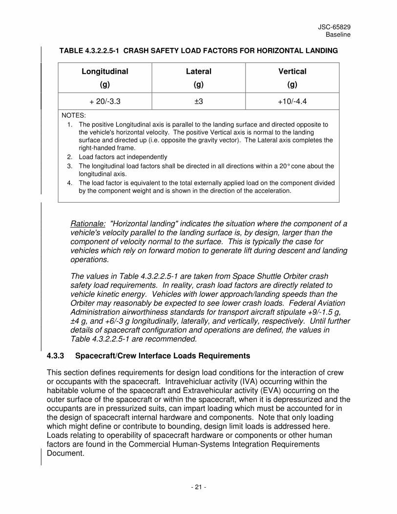
4.3.2.2.5 Crash Safety Loads for Horizontal Landing
[LD0032] Items within the crew compartment of lifting-body or other aircraft-like spacecraft which land horizontally shall not break loose from their mounting locations and pose a risk to the crew or prevent egress from the vehicle when subject to the load factors defined in Table 4.3.2.2.5-1
JSC-65829 Baseline
- 21 -
TABLE 4.3.2.2.5-1 CRASH SAFETY LOAD FACTORS FOR HORIZONTAL LANDING
Longitudinal
(g)
Lateral
(g)
Vertical
(g)
+ 20/-3.3 ±3 +10/-4.4
NOTES:
1. The positive Longitudinal axis is parallel to the landing surface and directed opposite to
the vehicle's horizontal velocity. The positive Vertical axis is normal to the landing
surface and directed up (i.e. opposite the gravity vector). The Lateral axis completes the
right-handed frame.
2. Load factors act independently
3. The longitudinal load factors shall be directed in all directions within a 20° cone about the
longitudinal axis.
4. The load factor is equivalent to the total externally applied load on the component divided
by the component weight and is shown in the direction of the acceleration.
Rationale: "Horizontal landing" indicates the situation where the component of a vehicle's velocity parallel to the landing surface is, by design, larger than the component of velocity normal to the surface. This is typically the case for vehicles which rely on forward motion to generate lift during descent and landing operations.
The values in Table 4.3.2.2.5-1 are taken from Space Shuttle Orbiter crash safety load requirements. In reality, crash load factors are directly related to vehicle kinetic energy. Vehicles with lower approach/landing speeds than the Orbiter may reasonably be expected to see lower crash loads. Federal Aviation Administration airworthiness standards for transport aircraft stipulate +9/-1.5 g, ±4 g, and +6/-3 g longitudinally, laterally, and vertically, respectively. Until further details of spacecraft configuration and operations are defined, the values in Table 4.3.2.2.5-1 are recommended.
4.3.3 Spacecraft/Crew Interface Loads Requirements
This section defines requirements for design load conditions for the interaction of crew or occupants with the spacecraft. Intravehicluar activity (IVA) occurring within the habitable volume of the spacecraft and Extravehicular activity (EVA) occurring on the outer surface of the spacecraft or within the spacecraft, when it is depressurized and the occupants are in pressurized suits, can impart loading which must be accounted for in the design of spacecraft internal hardware and components. Note that only loading which might define or contribute to bounding, design limit loads is addressed here. Loads relating to operability of spacecraft hardware or components or other human factors are found in the Commercial Human-Systems Integration Requirements Document.
JSC-65829 Baseline
- 22 -
4.3.3.1 IVA Loads
[LD0033] Spacecraft Intra-vehicular hardware and equipment shall be capable of withstanding a crew inadvertent contact load of 154 lb (685 N), applied as a uniform pressure load over a 4" by 4" (10.16 cm by 10.16 cm) area. If this area is unavailable to inadvertent contact, the load shall be applied to the available contact area.
Rationale: This requirement does not apply to vehicle primary structure or extra-vehicular hardware and equipment. Unintentional damage can occur if crews inadvertently exert loads that exceed the design loads for hardware or equipment. Inadvertent loads can occur when crew push or kick off equipment or exert excessive force when performing an operation (such as turning a control during an emergency situation). Designers are to identify areas of crew activity and ascertain exposed hardware and equipment that may be vulnerable to crew contact and unintended forces. To avoid inadvertent damage, hardware and equipment may be protected (e.g., with covers or recessing), located to prevent contact, mounted to safely absorb impact (e.g., limited movement range or break away), or designed to be durable to crew loads.
4.3.3.2 EVA Loads
TBD
4.3.4 Spacecraft Requirements for Joint Operations with ISS
SSP-50808, International Space Station Structural to Commercial Orbital Transportation Services Interface Requirements Document governs interaction between the ISS and commercial crewed vehicles during arrival, docked, and departure operations. Requirements specific to loads and structural dynamics applicable to the SC are found in SSP-50808 and take precedence over this document for those mission phases.
5.0 MODEL, FORCING FUNCTION AND DATA REQUIREMENTS
5.1 MATH MODEL REQUIREMENTS
5.1.1 Coverage
[LD0034] Flight Vehicle providers shall develop a sufficient set of models, of appropriate types, to permit analysis of forcing functions and environments covering applicable frequency ranges for known loading events.
Rationale: Flight Vehicles are subjected to a broad array of loads and environments over the course of their mission profiles. Depending on the event, maximum responses may be driven by environments spanning a wide, and possibly varying, frequency ranges. A variety of analytical approaches and modeling techniques (eg. Finite Element Analysis (FEA), Boundary Element Analysis (BEA), Statistical Energy Analysis (SEA), etc.) may therefore be required to ensure that bounding-case design loads are appropriately identified.
JSC-65829 Baseline
- 23 -
For reference, the section titled Model Delivery Requirements For Vibroacoustic Criteria Development in Appendix B contains guidelines applicable to SEA and BEA model development.
[LD0035] The SCP shall develop models of all relevant configurations of the LAV from the point of separation from the LV in an abort case up to and including landing.
Rationale: The LAV may have to take on several configurations during abort flight and each must be assessed to assure functionality and crew survivability. The loads on the LAV are significant and of a wide frequency range.
[LD0036] The SCP shall develop distinct models of the LAV which are applicable to the frequency ranges of the environments which the LAV will encounter during aborts.
Rationale: The loads on the LAV are significant and of a wide frequency range and complete analytical coverage will likely require use of distinct models with different frequency applicability (eg. FEA, BEA, SEA)
[LD0037] The SCP shall develop models which are compatible with software readily available to the NASA community. This includes versions of the LAV models for analysis of aborts.
Rationale: The NASA community must be able to perform IV&V and failure investigations without dependency on the SC provider.
5.1.2 Models for Coupled Loads Analysis
[LD0038] Flight Vehicle providers shall develop finite element mathematical models for use in coupled load analysis and all other loads analyses.
Rationale: Finite element models are based on structural properties and geometry. The model may be a reduced version of a finite element model developed for stress analyses or may be a model developed specifically for load analysis. Regardless of the source, the modeling approach shall be aimed at producing accurate dynamic predictions (frequencies and mode shapes).
[LD0039] Flight Vehicle integrated system models for coupled loads analysis shall be of sufficient resolution and fidelity to represent subsystem and vehicle resonances up to at least 1.1 times the upper bound of the range of frequency content of the forcing functions for load events to be analyzed.
Rationale: Models must be able to accurately predict responses over the excitation frequency ranges in forcing functions. Insufficient fidelity or frequency representation in a coupled loads model will lead to errors in predicted loads and possible unconservative design. The flight vehicle models will directly support the following integrated system analyses:
JSC-65829 Baseline
- 24 -
a. Structural dynamic loading events such as pre-launch, liftoff, ascent, and staging
b. Structural dynamic characterization of guidance and control sensor mounting locations
c. Hydrodynamic characterization and fluid-structure coupling of significant liquid masses for use in structural loading and control interaction analysis
d. Thermal contraction effects
e. Pressure stiffening effects
f. Overall bending static aeroelastic effects
[LD0040] Flight Vehicle models developed for integration into a flight vehicle integrated system model for coupled loads analysis shall be of sufficient resolution and fidelity to represent subsystem and vehicle resonances up a model upper bound of no less than 1.5 (with 2.0 being a recommended best practice) times the highest forcing function frequency of interest for all loading events over the flight vehicle mission life cycle.
Rationale: Sub-models integrated into a system model must retain a frequency content greater than that which will be used for system response analysis. Note that models with different cutoff frequencies may be used in the analysis of different events, depending on the frequency content of the excitation.
5.1.3 Damping
[LD0041] Damping used for Flight Vehicle dynamic response analysis shall be 1% of critical unless data or experience demonstrates a better value.
Rationale: Ideally, damping should be based on test measurements of the actual structure, at amplitude levels that are representative of actual flight environments, or on experience with similar types of structures whenever possible. Truly reliable estimates of damping may only be obtained based on measurements of response for the actual structure. In practice, however, 1% is a value typically used for loads and dynamics analysis of aerospace structures.
[LD0042] The SCP shall provide LAV damping values and justification for their use in both ground and flight phases.
Rationale: Damping values used to correlate the models (including but not limited to FEM and SEA) with ground test data may be different from damping levels assumed for flight analyses. Damping has a direct impact on analysis results but is difficult to determine at flight levels. The SCP needs to be ready to submit the damping values to be used for NASA review and approval.
JSC-65829 Baseline
- 25 -
5.1.4 Data Recovery
[LD0043] Flight Vehicle providers shall define sets of requested data items to be recovered during loads analyses.
Rationale: Selected responses at key locations in the structure are required to develop design load cases for structural design and to support stress analysis and correlation to system level test and flight data. Insight into structural response provides a means to compare severity of different loading events and permit rationale selection of design load conditions. Requests may include maximum and minimum accelerations, displacements, loads, stresses and pressures at selected grid points and elements, responses recovered from Acceleration, Displacement, Load, Stress, and Pressure Transformation Matrices (ATMs, DTMs, LTMs, STMs, PTMs), or displacement, load, or stress indicator equations. In addition, recovery of certain responses may be needed to verify compliance with non-structural requirements. For example, crew member accelerations during landing are necessary to compute Brinkley Dynamic Response model results for Occupant Protection requirements.
5.1.5 Load Indicators
[LD0044] Flight Vehicle providers shall develop sets of load indicators for critical structure for all phases of the mission profile.
Rationale: Load indicators enable direct insight into stress states in critical vehicle structure at the external loads analysis level. Such insight is necessary to allow determination of relative severity among different load events and enable effective trades of potential load reduction approaches with possible design modification. In addition, load indicators are key metrics for multi-disciplinary design integration efforts such as abort trigger definition and trajectory development.
[LD0045] The SCP shall develop LAV load indicators applicable to the defined abort scenarios in Table 4.2.3, to be used in the aborts loads and structural analyses as well as to assess trajectory and structural interaction.
Rationale: Load indicators are needed to assess structural capability and they must be applicable to the specific abort conditions assessed. The LAV configuration and loading environment will differ significantly from the nominal ascent SC configuration and will require development of abort vehicle-specific models and accompanying load indicators. This requirement is in place to highlight this need.
5.1.6 Load Indicator Redlines
[LD0046] Flight Vehicle providers shall develop redlines associated with load indicators for critical structure for all phases of the mission profile.
JSC-65829 Baseline
- 26 -
Rationale: Load indicator redlines establish effective not-to-exceed limits for critical structure. Redlines enable relatively quick assessment of changes in environments, operations, loads assumptions, etc.
5.1.7 Model Verification
5.1.7.1 Loads Model Verification
[LD0047] Flight Vehicle providers shall verify loads models by modal survey tests, with the appropriate boundary conditions, to ensure the model is sufficiently accurate for load and deflection predictions.
Rationale: Model verification may be accomplished by a combination of spacecraft or element level and component level modal survey tests. In some cases, additional verification tests may be required due to the non-linear nature of the dynamic response, such as the landing model, which would require data from ground impact testing. Verification of spacecraft dynamic models may require off-loading systems that simulate the free-free boundary conditions of the spacecraft. For on-orbit configuration component models, the method to verify the stiffness of the on-orbit attachment points of the structure preferred by the ISS program is by mass loading these areas to exercise sufficient strain energy in the regions of the structure which are critical for the on-orbit configuration. When mass loading of on-orbit interfaces is not used to correlate the on-orbit model with ground modal tests, additional ground test data such as static deflection tests and/or strain data may be used to supplement the verification. Guidelines on loads model verification, including recommendations on mass representation, treatment of boundary conditions, correlation accuracy, treatment of uncertainty, simplified approaches, etc. can be found in the appropriate section of Appendix B.
[LD0048] Flight Vehicle modal survey tests shall measure and correlate all significant modes below the model upper bound frequency, consistent with the model resolution and fidelity requirement described in the Models for Coupled Loads Analysis section.
Rationale: Significant modes may be selected based on an effective mass calculation, but this set will be augmented by modes which are critical for specific load, deflection definition and/or component interface modes.
5.1.7.1.1 Loads Model Correlation Report
[LD0049] Flight Vehicle providers shall document model verification results in a model correlation report. As a minimum, this report shall contain:
a. A description of the baseline (pretest) dynamic math model
b. A description of the test article, test boundary conditions and available test data for the correlation
JSC-65829 Baseline
- 27 -
c. A comparison of test and analytical dynamic parameters, e.g., frequencies, mode shapes, orthogonality, etc. of significant modes relative to correlation goals and requirements in the Loads Model Verification section for both pre- and post-test correlation
1. Any deviations from correlation requirements and goals are to be explained with technical rationale and engineering judgment that justifies that the test/math model correlation is sufficient
d. A description of the changes made to pretest math model to improve the dynamic math model correlation
Rationale: This requirement establishes the means by which flight vehicle model correlation efforts will be captured. Specific correlation goals are to be provided in the Structural Verification Plan required for all flight hardware per JSC 65828
5.1.7.2 LAV Test Model Verification
[LD0050] The SCP shall verify LAV test models with the appropriate test data. This data may be from modal tests, instrumented vibration tests, static tests, mass properties measurements, instrumented ground transportation tests, or flight tests.
Rationale: Analytical models are critical to showing the integrity of the LAV but must be verified to data to be useful. However there are multiple test scenarios that may be used to derive this data.
5.1.8 ISS-imposed Model Requirements
The ISS Program has developed a Program-specific set of requirements for the forms of models required for joint ISS operations, model correlation, model verification and documentation, etc. Although these will eventually be specifically negotiated and signed-up to between the ISS Program and the spacecraft provider, inspection of the existing requirements may be useful to help scope the extent of possible future requirements. Therefore, model-related requirements from D684-10019-1, Space Station Loads Control Plan have been extracted and included as Appendix D of the RFI version of this document. Appendix D is provided for reference only, and does not represent a formal, defined, or complete requirement set for spacecraft.
5.2 DATA TRANSFER REQUIREMENTS
The requirements in the following sections are intended to identify the deliverables required to be provided by the LVP and SCP. Delivery of all models and forcing function, environment, and output request data will facilitate performance of the NASA IV&V role and position the NASA TA to quickly respond in the event of any flight anomalies which may occur.

JSC-65829 Baseline
- 28 -
5.2.1 SCP Deliveries
[LD0051] The SCP shall deliver all models developed for assessment of all Flight Vehicle mission phases and all associated output requests, load indicators, load indicator redlines, output transformation matrices, and model documentation to the NASA TA.
[LD0052] The SCP shall deliver coupled loads analysis models for all mission phases up to the point of SC separation from the LV to the NASA TA.
[LD0053] The SCP shall deliver SC coupled loads analysis models for all mission phases up to the point of SC separation from the LV to the LVP.
[LD0054] The SCP shall deliver coupled loads analysis model output requests, load indicators, load indicator redlines output transformation matrices, and model documentation for all mission phases up to the point of SC separation from the LV to the NASA TA.
[LD0055] The SCP shall deliver SC coupled loads analysis model output requests, load indicators, load indicator redlines output transformation matrices, and model documentation for all mission phases up to the point of SC separation from the LV to the LVP.
[LD0056] The SCP shall deliver all LAV models developed for abort assessment and all associated output requests, load indicators, load indicator redlines, output transformation matrices, and model documentation to the NASA TA.
[LD0057] The SCP shall deliver LAV load indicators applicable to the defined abort conditions in Table 4.2.3 to the NASA TA.
[LD0058] The SCP shall deliver forcing functions, induced environments, and loads for all mission phases at and after the point of SC separation from the LV to the NASA TA.
[LD0059] The SCP shall deliver initial condition data developed for use in entry, descent, and landing analyses to the NASA TA.
[LD0060] The SCP shall deliver coupled loads analysis models of the on-orbit spacecraft configuration for use in ISS joint operations analysis to the NASA TA.
[LD0061] The SCP shall deliver SC coupled loads analysis models of the on-orbit spacecraft configuration for use in ISS joint operations analysis to the ISS Program.
[LD0062] The SCP shall deliver ISS approach and separation jet thruster firing histories and associated range and relative attitude data to the NASA TA.
[LD0063] The SCP shall deliver SC ISS approach and separation jet thruster firing histories and associated range and relative attitude data to the ISS Program.
JSC-65829 Baseline
- 29 -
[LD0064] The SCP shall deliver ISS docking contact condition data to the NASA TA.
[LD0065] The SCP shall deliver SC ISS docking contact condition data to the ISS program.
[LD0066] The SCP shall deliver the plume impingement flowfield model for SC jet thrusters to the NASA TA.
[LD0067] The SCP shall deliver the plume impingement flowfield model for SC jet thrusters to the ISS Program.
[LD0068] The SCP shall deliver SC jet thruster geometry and orientation data to the NASA TA.
[LD0069] The SCP shall deliver SC jet thruster geometry and orientation data to the ISS Program.
5.2.2 LVP Deliveries
[LD0070] The LVP shall deliver all models developed for assessment of all Flight Vehicle mission phases and all associated output requests, load indicators, load indicator redlines, output transformation matrices, and model documentation to the NASA TA.
[LD0071] The LVP shall deliver forcing functions, induced environments, and output data requested by the LV and SCP for all mission phases up to the point of SC separation from the LV to the NASA TA.
[LD0072] The LVP shall deliver LV forcing functions, induced environments, and output data requested by the SCP for all mission phases up to the point of SC separation from the LV to the SCP.
[LD0073] The LVP shall deliver bounding-case quasi-static and dynamic conditions at the SC separation event to the NASA TA.
[LD0074] The LVP shall deliver bounding-case quasi-static and dynamic conditions at the SC separation event to the SCP.
[LD0075] The LVP shall deliver bounding-case quasi-static and dynamic conditions at the point of SC separation for the abort failure cases in Table 4.2.3 to the NASA TA.
[LD0076] The LVP shall deliver bounding-case quasi-static and dynamic conditions at the point of SC separation for the abort failure cases in Table 4.2.3 to the SCP.
6.0 DYNAMIC COUPLING REQUIREMENTS
This section establishes a set of requirements covering coupling phenomena or other interaction between structural dynamics and aerodynamic environments, vehicle control
JSC-65829 Baseline
- 30 -
systems, or propulsion system elements. Such requirements encompass multiple design criteria including structures, propulsion, aerodynamic, and control system architecture. However the coupling of these aspects with structural dynamic dictates that these requirements be are included herein, to ensure that such considerations are not overlooked in the design space for NASA and commercial launch vehicles and spacecraft.
6.1 AEROELASTICITY
[LD0077] Flight Vehicle providers shall account for static and dynamic structural deformations and responses including the effect of aeroelasticity under all limit conditions and environments in the structural design of said vehicles.
Rationale: Combined effects of aerodynamic loading and structural response must be accounted for in vehicles which perform atmospheric flight. The vehicle structure must be stiff enough so that static elastic deflection will not cause structural failure or detrimental deformation, or degrade stability and control below specified levels.
[LD0078] Static and dynamic structural deformations and responses including the effect of aeroelasticity under all limit conditions and environments shall not cause a system malfunction, preclude the stable control of the Flight Vehicles or cause unintentional contact between adjacent bodies.
Rationale: Combined effects of aerodynamic loading and structural response must be accounted for in vehicles which perform atmospheric flight. The vehicle structure must be stiff enough so that static elastic deflection will not cause structural failure or detrimental deformation, or degrade stability and control below specified levels
6.2 STATIC AEROELASTICITY
6.2.1 Divergence
[LD0079] Flight Vehicles shall be free from divergence at dynamic pressures up to: (1) 1.32 times the maximum dynamic pressure expected at any point along the dispersed ascent and entry design trajectories; (2) the maximum dynamic pressure expected along the dispersed abort trajectories; or (3) 1.32 times the maximum dynamic pressure expected at any point during atmospheric flight, with or without control surfaces activated.
Rationale: Divergence will result in loss of vehicle structural integrity and loss of crew. Therefore, CCPD flight vehicle design should preclude the possibility of divergence.
[LD0080] Dynamic-pressure margins for divergence for Flight Vehicles shall be determined separately at constant density and at constant Mach number for all points within the atmospheric flight envelope, with or without control surfaces activated.
JSC-65829 Baseline
- 31 -
Rationale: The divergence evaluation should include, as appropriate, such factors as static and transient thermal effects on distortion and stiffness, loading magnitudes and distributions for al critical conditions, stiffness characteristics of the control-surface actuator system, system tolerances, misalignments, and mechanical play. For recommended practices, refer to NASA SP-8003.
6.2.2 Control System Reversal
[LD0081] Active aerodynamic control surfaces of Flight Vehicles shall not exhibit reversal up to the maximum dynamic pressure expected at any Mach number within the dispersed flight envelope for any given flight regime.
Rationale: Control reversal may lead to loss of control of the flight vehicle and loss of crew. Therefore, CCPD flight vehicle design should preclude control system reversal. For recommended practices, refer to NACA TN-3030. During an aborted flight, sufficient control effectiveness should be retained to permit the safe return of the vehicle and personnel.
6.3 DYNAMIC AEROELASTICITY
6.3.1 Flutter
[LD0082] Flight Vehicles shall be free from flutter at dynamic pressures up to: (1) 1.32 times the maximum dynamic pressure expected at any point along the dispersed ascent and entry design trajectories; (2) the maximum dynamic pressure expected at any point along the dispersed abort trajectory; or (3) 1.32 times the maximum dynamic pressure expected at any point during atmospheric flight, with or without control surfaces activated.
Rationale: Flutter produces sustained-amplitude oscillations or diverging oscillations leading to structural failure. Sustained-amplitude oscillations can produce fatigue failures. In either situation, loss of crew is a significant possibility. Therefore, CCPD flight vehicle design should preclude flutter. For further information, refer to NASA SP-8003.
[LD0083] Dynamic-pressure margins for flutter for Flight Vehicles shall be determined separately at constant density and at constant Mach number for all points within the atmospheric flight envelope, with or without control surfaces activated.
Rationale: The evaluation should account for all pertinent aerodynamic, elastic, inertial, and damping parameters, and coupling mechanisms (e.g., mechanical, elastic and aerodynamic), as well as the effects of control-system characteristics and mechanical play, misalignments, interface stiffnesses, and degrees of freedom of the cryogenic tank-support structure. If staging can occur in the atmosphere, the changes in vibration-mode characteristics and in the characteristics of the newly activated control surfaces should be accounted for, as well as the location of the lifting or control surfaces on the separating stages. For recommended practices, refer to NASA SP-8003.

JSC-65829 Baseline
- 32 -
6.3.2 Panel Flutter
[LD0084] Flight Vehicle external surfaces shall be free of panel flutter at all dynamic pressures up to: (1) 1.5 times the local dynamic pressure expected at any Mach number along the dispersed ascent and entry design trajectories; (2) 1.5 times the maximum dynamic pressure expected at any point during atmospheric flight; and (3) the maximum dynamic pressure expected for the dispersed abort trajectories.
Rationale: Panel flutter results in sustained oscillations in thin plate- or shell-like elements of a vehicle which can cause 1) structural failure of the panel or supporting structure, 2) functional failure of equipment attached to the structure, or 3) excessive noise levels in space vehicle compartments near the fluttering panel. Panel flutter may be destructive, potentially leading to loss of vehicle structural integrity and loss of crew. Therefore, CCPD flight vehicle design should preclude panel flutter. For further information, refer, refer to NASA SP-8004.
[LD0085] Dynamic-pressure margins for panel flutter for Flight Vehicles shall be determined separately at constant density and at constant Mach number for all points within the atmospheric flight envelope.
Rationale: The structural design of panel configurations for flutter prevention should be based upon consideration of the following parameters: panel stiffness, edge constraints, panel-support-structure stiffness, midplane stresses, thermal environment, local dynamic pressure and Mach number, differential pressure (including the effects of venting), and direction of flow. Panel flutter should be prevented in all modes including the first-vibration mode and in traveling-wave and standing-wave phenomena. NASA SP-8004 may be used as a guideline for designing panel surfaces.
[LD0086] Maximum nominal dynamic pressure for environmental and system dispersions used in panel flutter margin determinations for Flight Vehicles shall not exceed dispersed dynamic pressure used for the structural design or ascent stability constraints.
Rationale: The structural design of panel configurations for flutter prevention should be based upon consideration of the following parameters: panel stiffness, edge constraints, panel-support-structure stiffness, midplane stresses, thermal environment, local dynamic pressure and Mach number, differential pressure (including the effects of venting), and direction of flow. Panel flutter should be prevented in all modes including the first-vibration mode and in traveling-wave and standing-wave phenomena. NASA SP-8004 may be used as a guideline for designing panel surfaces.
6.3.3 Stall Flutter
[LD0087] Flight Vehicles shall be free of stall flutter at 1.32 times the dynamic pressure expected for high angle-of-attack maneuvers.

JSC-65829 Baseline
- 33 -
Rationale: Stall flutter can result in loss of vehicle control and/or produces sustained-amplitude or diverging oscillations which lead structural failure. In either situation, loss of crew is a significant possibility. Therefore, CCPD flight vehicle design should preclude stall flutter.
[LD0088] Separated aerodynamic-flow effects associated with lifting and stabilizing surfaces in high angle-of-attack maneuvers shall not result in structural failure or loss of control.
Rationale: A parametric evaluation of vehicle stall-flutter characteristics should be conducted to determine the aeroelastic characteristics necessary to avoid limit-cycle amplitude responses that could induce adverse loads on the structure. The evaluation should consider:
1. Separated-flow characteristics under all anticipated conditions of angle of attack and speed.
2. Stiffness, inertia, and damping characteristics of the aerodynamic surfaces.
3. All significant degrees of freedom.
6.3.4 Control Surface Buzz
[LD0089] Flight Vehicles, with or without control surfaces activated, shall be free of control-surface buzz at dynamic pressures up to: (1) 1.32 times the maximum dynamic pressure expected at any point along the dispersed ascent and entry design trajectories; and (2) 1.32 times the maximum dynamic pressure expected at any point during atmospheric flight.
Rationale: Control surface buzz can produce sustained-amplitude oscillations of control surface. Such oscillations can impair vehicle control system performance, leading to loss of control and/or can produce fatigue failures in control surfaces and actuators. In either situation, loss of crew is a significant possibility. Therefore, CCPD flight vehicle design should preclude control surface buzz. For further information, refer to NASA SP-8003.
[LD0090] Dynamic-pressure margins for control surface buzz for Flight Vehicles shall be determined separately at constant density and at constant Mach number for all points within the atmospheric flight envelope.
Rationale: Flight Vehicle control surfaces must not exhibit sufficient buzz to cause structural failure, loss of control of the vehicle, or otherwise prevent the safe return of personnel at the maximum dynamic pressure or at any Mach number along dispersed abort trajectories. The following considerations should be reflected in the design :
1. Aerodynamic configurations should be carefully selected so that flow-separation positions minimize the onset of buzz.
JSC-65829 Baseline
- 34 -
2. High torsional and rotational rigidity should be provided to ensure the highest practical rotational frequency.
3. The design should incorporate close tolerance bearings, actuator linkage, and attachments to minimize mechanical play.
For recommended practices, refer to NASA SP-8003.
6.4 INTERACTIONS BETWEEN VEHICLE FLIGHT CONTROL SYSTEM AND ELASTIC MODES
[LD0091] Flight Vehicles shall be free of instability or other interactions of the control system with the elastic modes which could impair flightworthiness.
Rationale: Unstable interaction between vehicle structural dynamics and flight control system can lead to catastrophic failure of the vehicle and loss of crew. The vehicle structure interfacing with the guidance and control system should be designed so that the excitations from the vehicle do not impair the performance of the guidance and control system or produce unacceptable error drift.
[LD0092] Structural characteristics of Flight Vehicles shall be defined in sufficient detail to permit analytical prediction of interactions of the control system with elastic modes.
Rationale: Accurate modeling of structures and structural dynamics is necessary to correctly analyze the interaction of vehicle control/structure interaction.
6.5 POGO DESIGN AND ANALYSIS REQUIREMENTS
[LD0093] Flight Vehicle design shall not permit unstable coupling of the structure with the liquid-propulsion system for all mission configurations.
Rationale: Unstable interaction between vehicle structural dynamics and liquid propulsion system can lead to catastrophic failure of the vehicle and loss of crew.
[LD0094] Uncertainties in the parametric values shall be accounted for by appropriate statistical means for establishing that the probability of a pogo instability during a vehicle flight is sufficiently small. As a minimum requirement, the nominal coupled system shall be stable at all times of flight for the following two conditions imposed separately: (1)the damping of all structural modes is halved simultaneously (this corresponds to a damping gain margin of at least 6 dB), and (2) any phase shift up to -+30 degrees is applied simultaneously to all the structural modes (this corresponds to a structural phase margin of 30 deg). When possible, the stability analysis shall be checked by a comparative analysis of the stability characteristics of closely related vehicles that have flown.
Rationale: Adequate coverage of system response variability as a function of parametric uncertainties must be assured. A minimum criteria for pogo stability must be defined and verified.

JSC-65829 Baseline
- 35 -
6.6 SLOSH
[LD0095] The need for slosh-suppression devices for Flight Vehicles shall be determined on the basis of dynamic analyses which consider the impact of slosh damping on overall vehicle loads, propellant tank local loads, control-system effectiveness, and overall vehicle stability.
Rationale: Slosh is not a driver for primary structure design, but has the potential to negatively impact vehicle flight control system performance. Typically, the need for slosh suppression is driven by a propellant slosh mode damping level required for control system stability.
[LD0096] Flight Vehicle slosh-suppression devices shall be designed to provide the specified levels of slosh damping, to function compatibly with all other systems in the vehicle, and to maintain their structural integrity under all applied loads
Rationale: Slosh is not a driver for primary structure design, but has the potential to negatively impact vehicle flight control system performance. Typically, the need for slosh suppression is driven by a propellant slosh mode damping level required for control system stability.
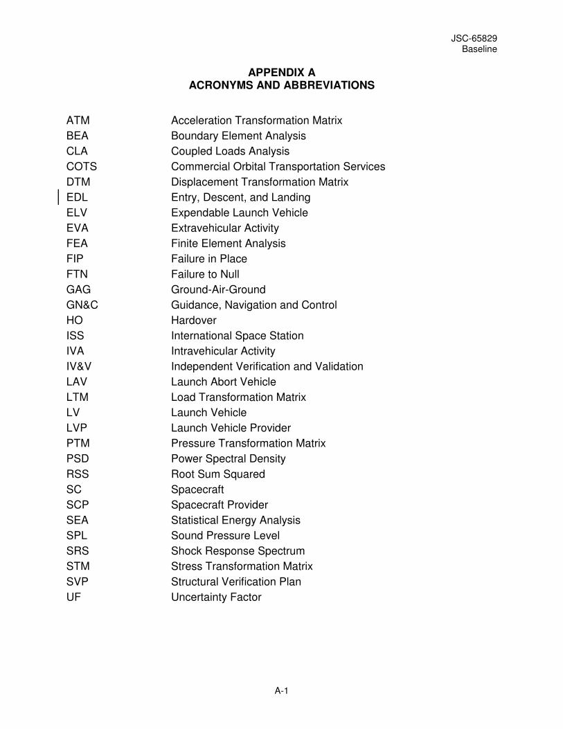
JSC-65829 Baseline
A-1
APPENDIX A ACRONYMS AND ABBREVIATIONS
ATM Acceleration Transformation Matrix
BEA Boundary Element Analysis
CLA Coupled Loads Analysis
COTS Commercial Orbital Transportation Services
DTM Displacement Transformation Matrix
EDL Entry, Descent, and Landing
ELV Expendable Launch Vehicle
EVA Extravehicular Activity
FEA Finite Element Analysis
FIP Failure in Place
FTN Failure to Null
GAG Ground-Air-Ground
GN&C Guidance, Navigation and Control
HO Hardover
ISS International Space Station
IVA Intravehicular Activity
IV&V Independent Verification and Validation
LAV Launch Abort Vehicle
LTM Load Transformation Matrix
LV Launch Vehicle
LVP Launch Vehicle Provider
PTM Pressure Transformation Matrix
PSD Power Spectral Density
RSS Root Sum Squared
SC Spacecraft
SCP Spacecraft Provider
SEA Statistical Energy Analysis
SPL Sound Pressure Level
SRS Shock Response Spectrum
STM Stress Transformation Matrix
SVP Structural Verification Plan
UF Uncertainty Factor
JSC-65829 Baseline
Appendix B
B-1
APPENDIX B GUIDELINES FOR LOADS ANALYSIS OF SPECIFIC FLIGHT PHASES
This Appendix provides recommended guidelines for developing structural design limit loads and load spectra for spaceflight hardware. Considerations which should be taken into account in the assessment of the key events in typical vehicle life cycles are identified and some recommendations regarding analysis methodologies are offered. Also provided are some suggested guidelines for mathematical models developed for structural loads analysis and vibroacoustic analysis. The contents of Appendix B are not formal requirements. Rather, they reflect experience gained and best practices developed over a history of NASA spaceflight hardware design and development.

JSC-65829 Baseline
Appendix B
B-2
Guidelines for Loads Analysis of Specific Flight Phases
TABLE OF CONTENTS
SECTION PAGE
1.0 LOADS MANAGEMENT PLAN ........................................................................... B-6
1.1 LOADS AND DYNAMICS TEAM RESPONSIBILITIES ....................................... B-6
1.2 DESIGN LOADS ANALYSIS CYCLES ............................................................... B-6
1.3 LOADS ANALYSIS DOCUMENTATION ............................................................. B-6
1.4 FREQUENCY SEPARATION ............................................................................. B-7
1.5 LIMIT LOADS ..................................................................................................... B-7
1.5.1 Integrated Loads .................................................................................. B-8
1.5.2 Load Combination Restrictions ............................................................ B-8
1.5.3 Combining Low Frequency and Random Loads for Components and Attachments ......................................................................................... B-8
1.6 DEFINITION OF VEHICLE DYNAMICS CRITERIA ............................................ B-9
2.0 LOADS DEVELOPMENT METHODOLOGY ..................................................... B-10
2.1 TRANSPORTATION AND GROUND HANDLING ENVIRONMENTS ............... B-10
2.1.1 Transportation and Handling Load Factors ........................................ B-11
2.1.2 Vehicle Assembly at the Launch Site ................................................. B-14
2.1.3 Spacecraft Transportation at the Launch Site .................................... B-14
2.2 ROLLOUT TO PAD .......................................................................................... B-14
2.2.1 Launch Vehicle/Launch Platform Rollout Loads ................................. B-14
2.2.2 Ground Wind Loads During Rollout .................................................... B-15
2.3 LAUNCH PAD OPERATIONS .......................................................................... B-17
2.3.1 Seismic Loads During Pre-launch ...................................................... B-17
2.3.2 Static Launch Vehicle/Pad Pre-loads ................................................. B-18
2.3.3 Pre-Launch Ground Wind Loads at the Launch Pad .......................... B-18
2.3.4 Tanking-Induced Loads ..................................................................... B-21
2.3.5 Ground-test Firing Loads ................................................................... B-21
2.4 LIFTOFF ........................................................................................................... B-22
2.4.1 Ignition Overpressure ......................................................................... B-22
2.4.2 Thrust Buildup and Shutdown ............................................................ B-22
2.4.3 Thrust Oscillations ............................................................................. B-22
2.4.4 Ground Winds at Lift-off ..................................................................... B-22
JSC-65829 Baseline
Appendix B
B-3
2.4.5 Lift-off Vortex Shedding ..................................................................... B-23
2.4.6 Pad Separation .................................................................................. B-23
2.4.7 Lift-off Transient Elastic Body Response ............................................ B-23
2.4.8 Lift-off External Acoustic Noise .......................................................... B-24
2.4.9 Lift-off Random Vibration ................................................................... B-24
2.4.10 Maneuvers ......................................................................................... B-24
2.4.11 Thrust Misalignment........................................................................... B-24
2.4.12 Vehicle Quasi-Static Accelerations .................................................... B-24
2.4.13 Venting .............................................................................................. B-24
2.4.14 Pogo Dynamics .................................................................................. B-24
2.4.15 Over-Turning Moment (OTM) ............................................................. B-25
2.5 ASCENT ........................................................................................................... B-25
2.5.1 Wind and Gust Criteria ....................................................................... B-26
2.5.2 Static Aeroelastic Effects ................................................................... B-27
2.5.3 Aerodynamic Flutter- and Divergence-Induced Loads ........................ B-27
2.5.4 Ascent Acoustic Noise ....................................................................... B-27
2.5.5 Venting .............................................................................................. B-27
2.5.6 Ascent Random Vibration .................................................................. B-28
2.5.7 Ascent Aerobuffeting.......................................................................... B-28
2.5.8 Ascent Aerodynamic Shock Loading .................................................. B-28
2.5.9 Steady-State Aerodynamic Loads ...................................................... B-29
2.5.10 Ascent Aerothermal Loading .............................................................. B-29
2.5.11 Stage Separation ............................................................................... B-29
2.5.12 Fairing Separation ............................................................................. B-29
2.5.13 Pyrotechnic Shock ............................................................................. B-29
2.5.14 Slosh ................................................................................................. B-29
2.5.15 Reaction Control System Operation ................................................... B-30
2.5.16 Thrust Loads ...................................................................................... B-30
2.5.17 Thrust Misalignment........................................................................... B-30
2.5.18 Engine Gimbal Effects ....................................................................... B-30
2.5.19 Thrust Gimbal Hard-Over ................................................................... B-31
2.5.20 Engine-out Conditions ........................................................................ B-31
2.5.21 Crew Escape System Jettison ........................................................... B-31
2.5.22 Environments for Spacecraft Cargo ................................................... B-31

JSC-65829 Baseline
Appendix B
B-4
2.5.23 Thrust Oscillation ............................................................................... B-31
2.5.24 Vehicle Quasi-Static Accelerations .................................................... B-31
2.5.25 Separation Motors ............................................................................. B-31
2.5.26 Ullage-Induced Loads ........................................................................ B-31
2.5.27 Ignition Transient and Thrust Buildup ................................................. B-32
2.5.28 Plume Loads Between Separated Stages .......................................... B-32
2.5.29 Self-Induced Mechanical Vibration ..................................................... B-32
2.6 LAUNCH/ASCENT ABORTS ............................................................................ B-32
2.6.1 Pad Abort ........................................................................................... B-32
2.6.2 Liftoff Abort ........................................................................................ B-32
2.6.3 Ascent Abort ...................................................................................... B-33
2.6.4 Fragmentation Environment ............................................................... B-34
2.6.5 Crew Escape System Motor Ignition Overpressure ............................ B-34
2.6.6 Crew Escape System Motor Plume Environment ............................... B-34
2.7 LOW EARTH ORBIT FREE-FLIGHT OPERATIONS ........................................ B-34
2.7.1 Low Earth Orbit (LEO) Insertion Burn ................................................ B-34
2.7.2 Loads on Deployable Structures ........................................................ B-34
2.7.3 Rendezvous Maneuvers .................................................................... B-34
2.7.4 Reaction Control System Operation ................................................... B-35
2.7.5 Internal Compartment Pressure-Induced Loads ................................. B-35
2.8 JOINT VEHICLE-TO-VEHICLE OPERATIONS ................................................ B-35
2.8.1 ISS Missions ...................................................................................... B-35
2.9 ENTRY, DESCENT AND LANDING ................................................................. B-37
2.9.1 Crew Re-entry Vehicle Entry Aerothermal and Aerodynamic Loads ... B-37
2.9.2 Deceleration System Deployment ...................................................... B-37
2.9.3 Cabin Pressure Equalization Loads ................................................... B-38
2.9.4 Land Landing ..................................................................................... B-38
2.9.5 Water Landing Initial Conditions ........................................................ B-39
2.10 EARTH RECOVERY ........................................................................................ B-39
2.10.1 Vehicle Hoisting and Handling ........................................................... B-39
2.10.2 Human Acceleration Limits ................................................................ B-39
3.0 UNCERTAINTY FACTORS/FACTORS OF SAFETY ........................................ B-39
3.1 TREATMENT OF MODEL/LOADS UNCERTAINTY FACTORS ....................... B-39
3.2 FACTORS OF SAFETY .................................................................................... B-40

JSC-65829 Baseline
Appendix B
B-5
4.0 LOADS AND LOAD SPECTRA COMBINATION............................................... B-40
4.1 COMBINATION OF MECHANICAL LOADS ..................................................... B-40
4.1.1 Transportation and Ground Handling ................................................. B-41
4.1.2 Vehicle Assembly at Launch Site ....................................................... B-41
4.1.3 Launch Pad Operations ..................................................................... B-41
4.1.4 Combining Liftoff Loads ..................................................................... B-41
4.1.5 First Stage Ascent Loads ................................................................... B-42
4.1.6 Stage Separation Loads .................................................................... B-42
4.1.7 Second and Subsequent Stage Ascent Loads ................................... B-42
4.1.8 Upper Stage Separation Loads .......................................................... B-42
4.1.9 Loads for ISS Rendezvous, Proximity Operations, Docking and Undocking and Spacecraft Mated Operations with ISS ........................................ B-43
4.2 FATIGUE LOADS SPECTRA DEVELOPMENT ............................................... B-43
4.3 COMBINATION OF TRANSIENT LOADS, PRESSURE AND THERMAL LOAD SPECTRA ........................................................................................................ B-43
5.0 STRUCTURAL DYNAMIC MATH MODEL GUIDELINES ................................. B-44
5.1 MODEL DELIVERY FOR LOADS DEVELOPMENT ......................................... B-44
5.1.2 Unique Requirements for Spacecraft Models for ISS On-orbit Mated Analysis ............................................................................................. B-49
5.1.3 ISS Loads Model Unique Requirements ............................................ B-49
5.2 STRUCTURAL MATH MODEL VERIFICATION ............................................... B-49
5.2.1 Loads Model Verification .................................................................... B-50
5.3 MODEL CORRELATION REPORT .................................................................. B-52
5.4 MODEL DELIVERY GUIDELINES FOR VIBROACOUSTIC CRITERIA DEVELOPMENT .............................................................................................. B-52
5.4.1 Configuration Control and Data Management .................................... B-53
5.4.2 Vibroacoustic Model Inputs ................................................................ B-53
5.4.3 Vibroacoustic Model Development and Quality Assurance ................ B-54
5.4.4 Vibroacoustic Model Outputs ............................................................. B-56
5.4.5 Model Correlation to Test/Flight Data ................................................. B-57
LIST OF TABLES
TABLE 1.5.3-1 LOAD COMBINATION CRITERIA FOR COMPONENTS ............................. B-9
TABLE 2.1.1-1 TRANSPORTATION AND HANDLING LIMIT LOAD FACTORS ................ B-13
APPENDICES
APPENDIX 1 ACRONYMS AND ABBREVIATIONS AND GLOSSARY OF TERMS ........... B-59

JSC-65829 Baseline
Appendix B
B-6
1.0 LOADS MANAGEMENT PLAN
1.1 LOADS AND DYNAMICS TEAM RESPONSIBILITIES
Programs and Projects should identify and establish an organization which has ultimate technical authority (TA) over the development and definition of structural design loads requirements. The TA should have the responsibility to manage, make decisions, provide direction, review, resolve issues, and provide integration across all engineering disciplines in the areas of loads and structures activities, both as an integrated vehicle and as separate systems within a Program/Project.
TA team membership should be composed of representatives from NASA and contractors from the various system developers responsible for deriving design loads. The team would provide a technical forum for identification and resolution of loads integration issues. The team members will
a. develop loads criteria and coordinate math model requirements and load case definition, loads data output requests, and delivery schedules,
b. define analysis plans and tasks and track them to completion,
c. identify technical issues and provide technical review to reach a consensus, if possible, on recommendations to resolve these issues,
d. define Verification and Validation (V&V) requirements for math models and forcing functions used in loads derivation, and
e. provide a single forum to coordinate resolution of loads integration issues.
1.2 DESIGN LOADS ANALYSIS CYCLES
Design loads should be developed to support major milestones, including the Design and Analysis Cycles (DACs) and Verification Analysis Cycles (VACs). The VAC must use test verified models and forcing functions to support Flight Readiness Reviews.
1.3 LOADS ANALYSIS DOCUMENTATION
Formal documentation of loads analysis results should, at a minimum, capture
a. major interface loads between systems,
b. a comparison of major interface loads and selected structural design loads with the analysis results of each load cycle,
c. a description of the analysis methodology and assumptions used in each loads cycle, and
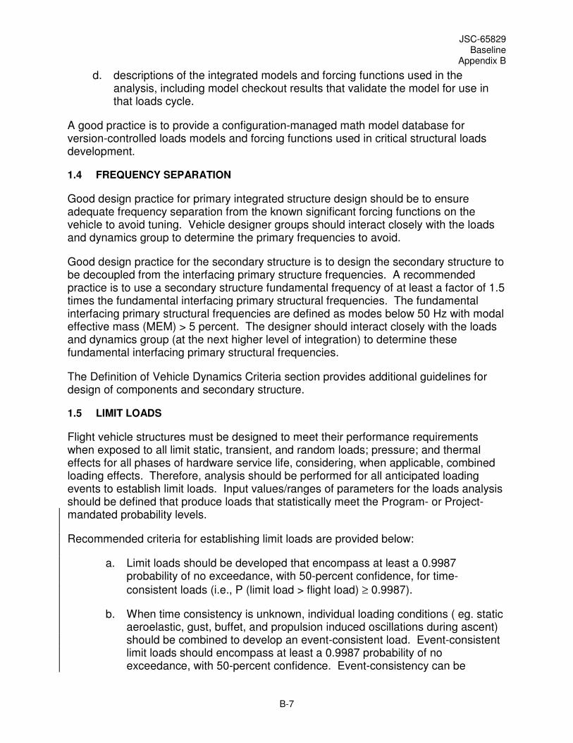
JSC-65829 Baseline
Appendix B
B-7
d. descriptions of the integrated models and forcing functions used in the analysis, including model checkout results that validate the model for use in that loads cycle.
A good practice is to provide a configuration-managed math model database for version-controlled loads models and forcing functions used in critical structural loads development.
1.4 FREQUENCY SEPARATION
Good design practice for primary integrated structure design should be to ensure adequate frequency separation from the known significant forcing functions on the vehicle to avoid tuning. Vehicle designer groups should interact closely with the loads and dynamics group to determine the primary frequencies to avoid.
Good design practice for the secondary structure is to design the secondary structure to be decoupled from the interfacing primary structure frequencies. A recommended practice is to use a secondary structure fundamental frequency of at least a factor of 1.5 times the fundamental interfacing primary structural frequencies. The fundamental interfacing primary structural frequencies are defined as modes below 50 Hz with modal effective mass (MEM) > 5 percent. The designer should interact closely with the loads and dynamics group (at the next higher level of integration) to determine these fundamental interfacing primary structural frequencies.
The Definition of Vehicle Dynamics Criteria section provides additional guidelines for design of components and secondary structure.
1.5 LIMIT LOADS
Flight vehicle structures must be designed to meet their performance requirements when exposed to all limit static, transient, and random loads; pressure; and thermal effects for all phases of hardware service life, considering, when applicable, combined loading effects. Therefore, analysis should be performed for all anticipated loading events to establish limit loads. Input values/ranges of parameters for the loads analysis should be defined that produce loads that statistically meet the Program- or Project-mandated probability levels.
Recommended criteria for establishing limit loads are provided below:
a. Limit loads should be developed that encompass at least a 0.9987 probability of no exceedance, with 50-percent confidence, for time-
consistent loads (i.e., P (limit load > flight load) ≥ 0.9987).
b. When time consistency is unknown, individual loading conditions ( eg. static aeroelastic, gust, buffet, and propulsion induced oscillations during ascent) should be combined to develop an event-consistent load. Event-consistent limit loads should encompass at least a 0.9987 probability of no exceedance, with 50-percent confidence. Event-consistency can be
JSC-65829 Baseline
Appendix B
B-8
developed via loads combination equations, Monte Carlo, or other suitable methods.
c. Loads resulting from the application of environments or excitations that are considered to be random in nature should be developed that encompass at least a 0.9987 probability of no exceedance, with 50-percent confidence, by flight loads arising from such environments/excitations.
1.5.1 Integrated Loads
For vehicles which may change configuration during a mission, all integrated configurations should be considered for integrated loads. For integrated vehicle flight, systems should be designed to maintain required functionality and positive margins for all induced loads and deformations, including dynamic interactions between mated stages and thermal environments. Verification of integrated loads may be performed by integrated analysis and/or test.
1.5.2 Load Combination Restrictions
Guidelines for combining mechanical loads may be found in NASA-TM-X-73305, Astronautic Structures Manual.
1.5.3 Combining Low Frequency and Random Loads for Components and Attachments
The effects of low frequency transient loads and random vibration/acoustic loads should be combined in a rational manner to determine the total load environment. Programs and/or Projects typically define criteria for combining loads from these different sources. Time-consistent loads may also be considered in the final loads cycle.
Three basic types of flight environments generate dynamic loads on flight vehicle components:
a. Low-frequency dynamic response, typically from 0 to 50 Hertz (Hz), of the launch vehicle/spacecraft system to transient flight events.
b. High-frequency random vibration environment, which typically has significant energy in the frequency range from 20 Hz to 2000 Hz, transmitted from the launch vehicle to the spacecraft at the launch vehicle/spacecraft interfaces.
c. High frequency acoustic pressure environment, typically 31 Hz to 10,000 Hz, inside the launch vehicle or spacecraft compartment. The payload compartment acoustic pressure environment generates dynamic loads on components in two ways: (1) by direct impingement on the surfaces of exposed components, and (2) by the acoustic pressure impingement upon the component mounting structures, which induces random vibrations that are mechanically transmitted to the components.

JSC-65829 Baseline
Appendix B
B-9
Combinations of these loads occur at different times in flight and should be examined for each flight event. For components weighing less than 500 kg, the appropriate method of load combination is dependent on how the low frequency and the random vibration/acoustic design environments of the event are specified. Typically, the maximum levels are defined as requirements for a flight event, such as liftoff, even if these maxima do not necessarily occur at the same time. The relative timing of the transient and random vibration environments is unique for each launch vehicle, but simultaneous occurrence of maximum low frequency transient and maximum random vibration load is improbable. Therefore, an RSS approach is acceptable for combining the maximum low frequency and maximum random vibration loads for the liftoff flight event. When the low frequency transient and random vibration environments are specified in a time correlated manner, a time consistent approach is also acceptable for combining the low frequency transient loads and the random vibration loads.
Table 1.5.3-1 provides one recommended combination approach. V1, V2, and V3 represent the orthogonal directions of a coordinate reference frame for the component in question. The axes may or may not align with the vehicle reference frame. Care must be taken to ensure that the three combined load sources are appropriately defined with respect to the reference frame used.
TABLE 1.5.3-1 LOAD COMBINATION CRITERIA FOR COMPONENTS
Axis Steady State Load (Limit) Low Frequency
Transient Load1,2
Random Load
3
Vi QSi ±Si ±Ri
Combined Loads: Loads in Each Axis Acting Simultaneously4
Load Set V1 Axis V2 Axis V3 Axis
1 QS1 ± (S12 + R1
2)1/2
QS2 ± (S22 + (R2/3)
2)1/2
QS3 ± (S32 + (R3/3)
2)1/2
2 QS1 ± (S12 + (R1/3)
2)1/2
QS2 ± (S22 + R2
2)1/2
QS3 ± (S32 + (R3/3)
2)1/2
3 QS1 ± (S12 + (R1/3)
2)1/2
QS2 ± (S22 + (R2/3)
2)1/2
QS3 ± (S32 + R3
2)1/2
NOTES:
1. Quasi-static portion removed
2. Based on three-sigma predictions and case-consistent, when available
3. Three-sigma Gaussian random load
4. The off-axis contribution of random vibro-acoustics in each load set may be eliminated with approval of the NASA Technical Authority. This approach will be limited to cases where sufficient rationale is developed to ensure statistical coverage of combined flight loads.
1.6 DEFINITION OF VEHICLE DYNAMICS CRITERIA
A vehicle dynamics criteria spectrum should be defined to cover the frequency range from 0.5 –50 Hz. The criteria may be a simplified envelope based on vehicle response from coupled loads assessments, evaluated using spectral lines spaced at a maximum of 1 Hz from 0–10 Hz and 1/6th octave from 10–50 Hz. Sine sweep vehicle dynamics test criteria should be defined for a frequency band from 5-40 Hz at a minimum.

JSC-65829 Baseline
Appendix B
B-10
The set of vehicle response data used to assess each vibration zone should include the following:
a. Vehicle centerline response for each station.
a. Base input response at secondary structure/vehicle interfaces and/or component/vehicle interfaces on the vehicle side of the interface for secondary structure/component subsystems that have a fundamental interfacing primary structural frequency less than or equal to 50 Hz. (For example, if an isolator is present with the secondary structure/component subsystem, then provide the response on the vehicle side of the isolator.)
An example of a good practice that meets or exceeds the guidelines above can include:
a. Process the transient response data using a shock response spectrum (SRS) analyzer with a dynamic amplification factor (Q) of 10.
b. Normalize the results (i.e., divide by Q).
c. Evaluate each SRS using the following spectral lines: 0.5, 0.6, 0.7, 0.8, 0.9, 1.0–50 Hz by 1 Hz.
d. Envelope the results for each vehicle equipment mounting zone.
e. Evaluate the uncertainties and add margin to envelopes, if necessary.
2.0 LOADS DEVELOPMENT METHODOLOGY
Loads should be developed for all phases of hardware service life. Some recommendations on methodologies for assessing the many load events and environments over the lifetime of a flight vehicle are provided in the following sections.
2.1 TRANSPORTATION AND GROUND HANDLING ENVIRONMENTS
"Transportation" in this context includes transportation of vehicle elements as well as transport of vehicle sub-assemblies, stages, spacecraft, or other major components. It does not include rollout from the vehicle integration facility to the launch pad.
Ground handling operations include loading flight articles in and out of trucks, onto railroad cars or barges and into cargo planes, installing and removing fight articles into test fixtures, and lifting them into place for integration with the launch vehicle. Ground handling also includes post-landing recovery and retrieval.
Loads induced during ground handling operations can typically be characterized with static loads and shock loads. Although the ground handling environment is relatively benign, special handling precautions are often taken if the damage potential is severe. Procedures should be developed to ensure that ground handling operations do not impart loads to the vehicle that exceed design load values. Loads imposed by the
JSC-65829 Baseline
Appendix B
B-11
transportation and handling system may be predicted by one or more of the following analytical methods. NASA SP-8077, Transportation and Handling Loads, Prediction Methods for Transportation and Handling Loads section provides supplemental information of these approaches.
a. Limit load factors (constant "g") based on accumulated experience in transportation and handling are used as input to support points of the space vehicle.
b. Composite loads, synthesized from loads measured at the cargo load bed of the appropriate type of transport vehicle during previous shipments with many types of cargo, are used as forcing-function inputs to a mathematical model of the space vehicle and that portion of the transportation or handling system between the space vehicle and the transport vehicle cargo load bed.
c. Loads measured on a similar space vehicle during shipment or handling with the same or similar transportation or handling system are scaled or extrapolated to the space vehicle of interest by an analysis using mathematical models of both systems.
d. Loads from the environment external to the transportation or handling system are used as forcing-function inputs to a mathematical model of the space vehicle and its entire transportation or handling systems.
2.1.1 Transportation and Handling Load Factors
Flight hardware may be shipped by aircraft, trains or trucks, hoisted by cranes, moved by dolly, or transported by watercraft. Quasi-static load factors for preliminary design should developed to account for all relevant shipping events.
The Transportation and Handling Limit Load Factors table below provides representative limit load accelerations for element hardware of all sizes. However, for items that weigh less than 136.08 kg (300 lb) with no isolation system, additional assessment of accelerations caused by random vibration and acoustics for certain modes of transportation should be considered.
If the loads in the Transportation and Handling Limit Load Factors table exceed design limits for the flight hardware to be transported, special care must be taken to ensure that the transportation or handling equipment will in no way impose excessive loads on the flight hardware. During shipping, the hardware should be appropriately instrumented to assure that the transportation environment is enveloped by these load factors.
Limit loads for jacking and hoisting flight hardware should be based on the maximum gross weight of the vehicle. The vertical jacking load should be assumed to act singly and in combination with the longitudinal and lateral loads. The horizontal loads at the jack points are to be reacted by inertia forces to prevent any change in the vertical loads at the jack point.

JSC-65829 Baseline
Appendix B
B-12
Hoisting loads should be applied to the vehicle in any direction within 20 degrees of the axis in which the hoist operation will occur.
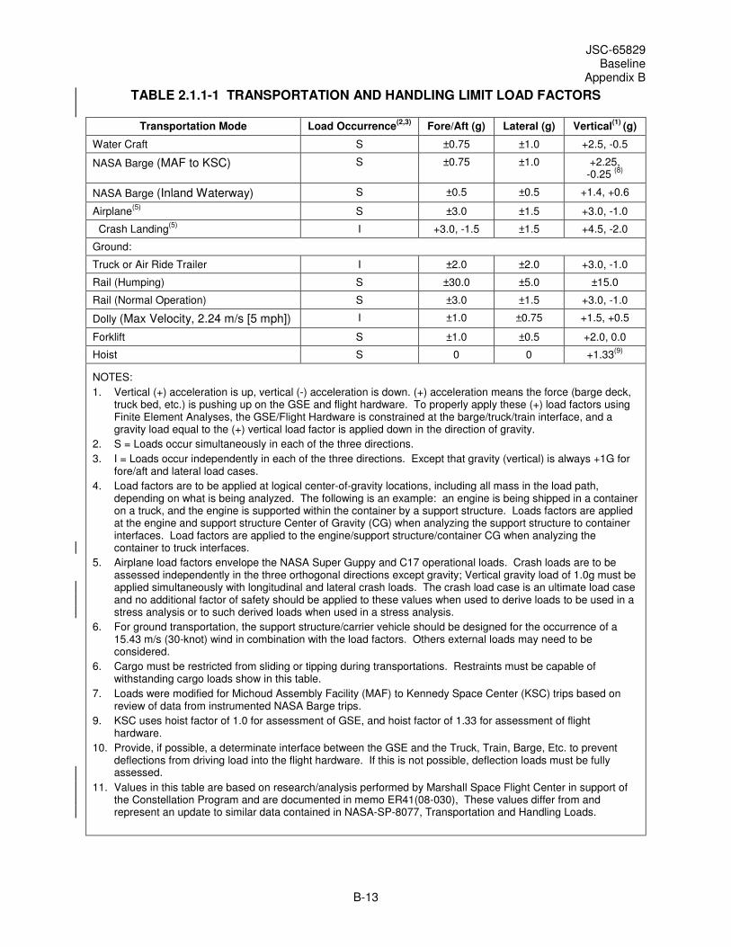
JSC-65829 Baseline
Appendix B
B-13
TABLE 2.1.1-1 TRANSPORTATION AND HANDLING LIMIT LOAD FACTORS
Transportation Mode Load Occurrence(2,3)
Fore/Aft (g) Lateral (g) Vertical(1)
(g)
Water Craft S ±0.75 ±1.0 +2.5, -0.5
NASA Barge (MAF to KSC) S ±0.75 ±1.0 +2.25, -0.25
(8)
NASA Barge (Inland Waterway) S ±0.5 ±0.5 +1.4, +0.6
Airplane(5)
S ±3.0 ±1.5 +3.0, -1.0
Crash Landing(5)
I +3.0, -1.5 ±1.5 +4.5, -2.0
Ground:
Truck or Air Ride Trailer I ±2.0 ±2.0 +3.0, -1.0
Rail (Humping) S ±30.0 ±5.0 ±15.0
Rail (Normal Operation) S ±3.0 ±1.5 +3.0, -1.0
Dolly (Max Velocity, 2.24 m/s [5 mph]) I ±1.0 ±0.75 +1.5, +0.5
Forklift S ±1.0 ±0.5 +2.0, 0.0
Hoist S 0 0 +1.33(9)
NOTES:
1. Vertical (+) acceleration is up, vertical (-) acceleration is down. (+) acceleration means the force (barge deck, truck bed, etc.) is pushing up on the GSE and flight hardware. To properly apply these (+) load factors using Finite Element Analyses, the GSE/Flight Hardware is constrained at the barge/truck/train interface, and a gravity load equal to the (+) vertical load factor is applied down in the direction of gravity.
2. S = Loads occur simultaneously in each of the three directions.
3. I = Loads occur independently in each of the three directions. Except that gravity (vertical) is always +1G for fore/aft and lateral load cases.
4. Load factors are to be applied at logical center-of-gravity locations, including all mass in the load path, depending on what is being analyzed. The following is an example: an engine is being shipped in a container on a truck, and the engine is supported within the container by a support structure. Loads factors are applied at the engine and support structure Center of Gravity (CG) when analyzing the support structure to container interfaces. Load factors are applied to the engine/support structure/container CG when analyzing the container to truck interfaces.
5. Airplane load factors envelope the NASA Super Guppy and C17 operational loads. Crash loads are to be assessed independently in the three orthogonal directions except gravity; Vertical gravity load of 1.0g must be applied simultaneously with longitudinal and lateral crash loads. The crash load case is an ultimate load case and no additional factor of safety should be applied to these values when used to derive loads to be used in a stress analysis or to such derived loads when used in a stress analysis.
6. For ground transportation, the support structure/carrier vehicle should be designed for the occurrence of a 15.43 m/s (30-knot) wind in combination with the load factors. Others external loads may need to be considered.
6. Cargo must be restricted from sliding or tipping during transportations. Restraints must be capable of withstanding cargo loads show in this table.
7. Loads were modified for Michoud Assembly Facility (MAF) to Kennedy Space Center (KSC) trips based on review of data from instrumented NASA Barge trips.
9. KSC uses hoist factor of 1.0 for assessment of GSE, and hoist factor of 1.33 for assessment of flight hardware.
10. Provide, if possible, a determinate interface between the GSE and the Truck, Train, Barge, Etc. to prevent deflections from driving load into the flight hardware. If this is not possible, deflection loads must be fully assessed.
11. Values in this table are based on research/analysis performed by Marshall Space Flight Center in support of the Constellation Program and are documented in memo ER41(08-030), These values differ from and represent an update to similar data contained in NASA-SP-8077, Transportation and Handling Loads.
JSC-65829 Baseline
Appendix B
B-14
2.1.2 Vehicle Assembly at the Launch Site
Vehicle assembly loads should be enveloped by vehicle design loads. The loads analysis should include both static and dynamic analysis with max weight, alignment tolerances, gravity effects, and operationally-induced loads imparted during the assembly operation. If elements are assembled that are fueled, propellant slosh loads and weights must be taken into account during assembly. Load assessment techniques are similar to those described in the Transportation and Handling Load Factors section.
2.1.3 Spacecraft Transportation at the Launch Site
Loads induced due to the transfer of vehicle stages, spacecraft or major components around the launch site in preparation for or during assembly should be assessed to verify that they are enveloped by the design loads. Load assessment techniques are similar to those described in the Transportation and Handling Load Factors section.
2.2 ROLLOUT TO PAD
2.2.1 Launch Vehicle/Launch Platform Rollout Loads
A pathfinder rollout should be performed for each unique launch configuration to validate that rollout loads are enveloped by vehicle design loads and to provide data to support life assessments for vehicle and launcher hardware.
Launch vehicle/launch platform rollout loads calculations should include the following considerations, vehicle rollout speeds, maximum wind effects, wind direction, and Wind Induced Oscillations (WIOs) for all unique vehicle configurations and constraints. In addition to the static axial load due to the weight of the stack, changing gravity moments resulting from the motion of structure mass items during a dynamic event should be considered. If a structural tie-off or damper to a launch support structure is used to help withstand wind or other forces imposed on the vehicle for rollout, the loads at the vehicle attachments must be included in the determination of the total vehicle loads.
If a vehicle is fueled during rollout, the effect of propellant slosh must be included in the system load calculation. Propellant slosh loads should be accurately determined for individual tank and baffle elements and should include, at a minimum, the effects of the physical properties of the fluid, the fluid level, and acceleration. The dynamic response of the vehicles to liquid sloshing can be calculated if an equivalent mechanical system is used to represent the liquid dynamics. Such mechanical systems are composed of fixed masses and oscillating masses connected to the tank by springs and dashpots or pendulums and dashpots, designed so that they have the same resultant pressure force, moment, damping, and frequency as the actual system.
The rollout loads assessment should also include emergency braking and turning, if applicable. The only dynamics in the problem are associated with the rise rate of applying or releasing the brakes. For turning, a rotational rate and centripetal acceleration appropriate to the means of transporting the vehicle should be included in the loads assessment.
JSC-65829 Baseline
Appendix B
B-15
2.2.2 Ground Wind Loads During Rollout
For each unique launch configuration, ground wind velocity and direction constraints for rollout should be developed and assessed. Ground wind speeds for rollout should be defined per Program-/Project-specific requirements. Wind directions should be considered at a minimum of every 30 degrees clocking, including the worst-case azimuth based on vehicle configuration. In addition to ground wind velocities, gusts, vortex shedding and local shielding, and amplifying effects of support structure or tower and umbilicals should be included in the loads assessment.
Ground wind effects are difficult to quantify. Subscale ground wind testing should be performed for each unique launch configuration, including significant launch pad structure and any dampers used to attenuate ground wind loads, and surrounding terrain. Such tests would validate that predicted ground wind loads represent enveloping design loads. The criteria for combining the vortex-shedding induced loads with the ground wind loads should also be developed based on this testing.
2.2.2.1 Steady-State Wind and Gust Loads
Appropriate combinations of steady-state wind, spectral turbulence/gust environments, and discrete (1-minus-cosine) gust environments should be considered.
2.2.2.2 Vortex Shedding or Wind Induced Oscillation (WIO) Loads
Vortex shedding or WIO effects can be represented by several methods:
2.2.2.2.1 Static Preliminary Design Analysis
a. Per NASA SP-8008, Prelaunch Ground Wind Loads, a combined wind and WIO load can be represented by a 1.5 factor on static ground wind forces applied as a single-direction load. These wind forces should be derived from the appropriate peak winds per Program/Project requirements for ground wind environments. These forces are applied along several possible clocking directions per the Ground Wind Loads During Rollout section. A drag coefficient of 1.0 for single cylinder or 1.5 for multi-cylinder vehicles should be used unless more appropriate values are available from test.
b. Alternately, the static peak wind forces with a 1.0 factor can be combined with a perpendicular static force equal to the static peak wind forces with a 1.5 factor. These wind forces should be derived from the appropriate peak winds per Program/Project requirements for ground wind environments. The force combinations should be applied along several possible clocking directions per the Ground Wind Loads During Rollout section. A drag coefficient for the longitudinal, or along wind, direction of 1.0 for single cylinder or 1.5 for multi-cylinder vehicles should be used unless more appropriate values are available from test. A lift coefficient for the lateral direction, or perpendicular wind, of 0.75 for single cylinder or 1.125 for multi-cylinder vehicles should be used unless more appropriate values are available from test.

JSC-65829 Baseline
Appendix B
B-16
2.2.2.2.2 Dynamic Preliminary Design Analysis
The following method should be used for preliminary design analyses, such as liftoff or initial stabilizer design, where dynamics are important. The longitudinal, or along, wind should be modeled as a static peak wind force with a 1.0 factor. The perpendicular WIO wind should be modeled as a 1-cosine wave with the peak-to-peak amplitude equal to the static peak wind forces with a 1.5 factor. The wavelength of the cosine wave should be tuned to the first cantilevered bending frequencies of the vehicle on the pad. For liftoff analyses, this wave should be timed such that the release occurs at either the maximum vehicle tip deflection or the maximum vehicle tip velocity. At release, the perpendicular WIO force is removed, while the longitudinal wind force continues.
These wind forces should be derived from the appropriate peak winds per Program/Project requirements for ground wind environments. These force combinations are applied along several possible clocking directions per the Ground Winds at Lift-off section. A drag coefficient for the longitudinal, or along wind, direction of 1.0 for single cylinder or 1.5 for multi-cylinder vehicles should be used unless more appropriate values are available from test. A lift coefficient for the lateral direction, or perpendicular wind, of 0.75 for single cylinder or 1.125 for multi-cylinder vehicles should be used unless more appropriate values are available from test.
2.2.2.2.3 Post-PDR Design Analysis
A lateral dynamic force should be combined with a longitudinal main wind direction steady state force. The lateral force should be a lateral WIO force predicted using rigorous load/structure interaction dynamics analysis methodology, tools, and test data, when available. These wind forces should be derived from the appropriate steady-state winds per Program/Project requirements for ground winds. Vortex shedding frequency lock-in with structural frequencies should be evaluated for the first four bending frequencies in any given direction of the vehicle on the pad.
These force combinations should be applied along several possible clocking directions per the Ground Winds at Lift-off section. A drag coefficient for the longitudinal, or along wind, direction of 1.0 for single cylinder or 1.5 for multi-cylinder vehicles should be used unless more appropriate values are available from test. A lift coefficient for the lateral direction, or perpendicular wind, of 0.6 for single cylinder or 0.9 for multi-cylinder vehicles should be used until more appropriate values are available from test.
2.2.2.3 Umbilical Loads
Loads induced on the launch vehicle due to the launch pad umbilicals and loads on the umbilicals should be developed by analysis supported by wind tunnel testing. Each unique launch configuration should be considered. The analysis should include the effects of umbilical configuration, method of attachment, method of disconnect, feed-line pressures, and wind loads.
JSC-65829 Baseline
Appendix B
B-17
2.2.2.4 Stabilization/Damper System Loads
Loads induced on the launch vehicle due to the stabilization/damper configuration, method of attachment, and method of disconnect should be developed by analysis.
2.2.2.5 Crew Access Arm Loads
Loads induced on the launch vehicle due to the crew access arm and loads on the crew access arm should be developed by analysis.
2.2.2.6 Ground Wind Fatigue Spectra
Ground wind fatigue load spectra should be developed for each unique launch configuration using the peak ground wind speed and frequency of occurrence probability distributions as provided in Program/Project requirements for ground winds environments. From these data, mean wind speed and gust values should be estimated and used to generate fatigue spectra loads. Wind induced oscillation must be included in the loads spectra, if significant.
2.3 LAUNCH PAD OPERATIONS
Vehicle and launch support structure loads arising during the period in which the vehicle is on the launch pad prior to launch must be evaluated. Loads can be induced on the stack and pad by natural environments such as seismic activity and ground winds and by pre-launch operations such as loading of cryogenic liquid commodities for the propulsion system and engine hot-fire tests.
2.3.1 Seismic Loads During Pre-launch
Depending on the location of the launch facility, earthquakes may be an important consideration. Although the probability is very small that an earthquake with a potentially damaging magnitude will occur during the relatively short time interval between the installation of a space vehicle on the launch pad and its launch, the possibility of such an occurrence must be considered. Of primary concern are the lateral loads that would be introduced at the base of the space vehicle by seismic induced horizontal motions of the launch pad, as well as those loads applied to a variety of ground support equipment and flight elements prior to launch, e.g., vehicle hardware in nearby storage.
If the launch pad is supported by a hard rock site, a conventional dynamic analysis of the vehicle on its pad may be performed to determine vehicle loads and deflections during an earthquake. However, if a softer site is utilized, soil-structure interaction must be considered. Soft soil supporting the pad can be expected to permit an excess of translational and especially rotational motion at the pad/vehicle interface, causing a reduction of the system natural frequencies, an increase in the relative displacements between vehicle and elements of the launch support structure, and sometimes an increase in the vehicle loads. On the other hand, system damping is greatly increased due to the response-induced generation of seismic waves back into the soil.
JSC-65829 Baseline
Appendix B
B-18
2.3.2 Static Launch Vehicle/Pad Pre-loads
For each unique launch configuration, static hold-down loads due to any constraint device must be developed, if applicable. If a structural tie-off or damper to a launch support structure is used to help withstand wind or other forces imposed on the vehicle for rollout, the loads at the vehicle attachments must be included in the determination of the total vehicle loads.
2.3.3 Pre-Launch Ground Wind Loads at the Launch Pad
Static and dynamic loads resulting from winds and gusts (and resultant vortex shedding) during pre-launch should be analyzed. Loads assessments should include, at a minimum, the effects of
a. the forward profile shape for the vehicle (e.g., vehicle nose);
b. vehicle mass, stiffness, propellant loads, and tank pressurization conditions;
c. protuberances and surface roughness;
d. proximity and shapes of umbilical masts; and
e. other large structures.
The resultant elastic vehicle static and dynamic loads should be obtained by suitable combination of the turbulence loads and steady loads, together with the periodic vortex-shedding loads calculated from the peak wind profile.
For each unique launch configuration, ground wind velocity and direction constraints for pre-launch operations at the launch pad should be developed and assessed. Ground wind speeds for pre-launch should be defined per Program-/Project-specific requirements. Wind directions should be considered at a minimum of every 30 degrees clocking, including the worst-case azimuth based on vehicle configuration. In addition to ground wind velocities, gusts, vortex shedding, and local shielding and amplifying effects of support structure or tower and umbilicals should be included in the loads assessment.
Ground wind effects are difficult to quantify. Subscale ground wind testing should be performed for each unique launch configuration, including significant launch pad structure and any dampers used to attenuate ground wind loads, and surrounding terrain to validate that predicted ground wind loads represent enveloping design loads. The criteria for combining the vortex-shedding induced loads with the ground wind loads should also be developed based on this testing.
2.3.3.1 Steady-State Wind and Gust Loads
Appropriate combinations of steady-state wind, spectral turbulence/gust environments, and discrete (1-minus-cosine) gust environments should be considered.
JSC-65829 Baseline
Appendix B
B-19
2.3.3.2 Vortex Shedding or Wind Induced Oscillation (WIO) Loads
Vortex shedding or WIO effects can be represented by several methods:
2.3.3.2.1 Static Preliminary Design Analysis
a. Per NASA SP-8008, Prelaunch Ground Wind Loads, a combined wind and WIO load can be represented by a 1.5 factor on static ground wind forces applied as a single-direction load. These wind forces should be derived from the appropriate peak winds per Program/Project requirements for ground wind environments. These forces are applied along several possible clocking directions per the Pre-Launch Ground Wind Loads at the Launch Pad section. A drag coefficient of 1.0 for single cylinder or 1.5 for multi-cylinder vehicles should be used unless more appropriate values are available from test.
b. Alternately, the static peak wind forces with a 1.0 factor can be combined with a perpendicular static force equal to the static peak wind forces with a 1.5 factor. These wind forces should be derived from the appropriate peak winds per Program/Project requirements for ground wind environments. The force combinations are applied along several possible clocking directions per the Pre-Launch Ground Wind Loads at the Launch Pad section. A drag coefficient for the longitudinal, or along wind, direction of 1.0 for single cylinder or 1.5 for multi-cylinder vehicles should be used unless more appropriate values are available from test. A lift coefficient for the lateral direction, or perpendicular wind, of 0.75 for single cylinder or 1.125 for multi-cylinder vehicles should be used unless more appropriate values are available from test.
2.3.3.2.2 Dynamic Preliminary Design Analysis
The following method should be used for preliminary design analyses, such as liftoff or initial stabilizer design, where dynamics are important. The longitudinal, or along, wind should be modeled as a static peak wind force with a 1.0 factor. The perpendicular WIO wind should be modeled as a 1-cosine wave with the peak-to-peak amplitude equal to the static peak wind forces with a 1.5 factor. The wavelength of the cosine wave should be tuned to the first cantilevered bending frequencies of the vehicle on the pad. For liftoff analyses, this wave should be timed such that the release occurs at either the maximum vehicle tip deflection or the maximum vehicle tip velocity. At release, the perpendicular WIO force is removed, while the longitudinal wind force continues.
These wind forces should be derived from the appropriate peak winds per Program/Project requirements for ground wind environments. These force combinations are applied along several possible clocking directions per the Ground Winds at Lift-off section. A drag coefficient for the longitudinal, or along wind, direction of 1.0 for single cylinder or 1.5 for multi-cylinder vehicles should be used unless more appropriate values are available from test. A lift coefficient for the lateral direction, or
JSC-65829 Baseline
Appendix B
B-20
perpendicular wind, of 0.75 for single cylinder or 1.125 for multi-cylinder vehicles should be used unless more appropriate values are available from test.
2.3.3.2.3 Post-PDR Design Analysis
A lateral dynamic force should be combined with a longitudinal main wind direction steady state force. The lateral force should be a lateral WIO force predicted using rigorous load-structure interaction dynamics analysis methodology, tools, and test data when available. These wind forces should be derived from the appropriate steady-state winds per Program/Project requirements for ground winds. Vortex shedding frequency lock-in with structural frequencies should be evaluated for the first four bending frequencies in any given direction of the vehicle on the pad.
These force combinations should be applied along several possible clocking directions per the Pre-Launch Ground Wind Loads at the Launch Pad section. A drag coefficient for the longitudinal, or along wind, direction of 1.0 for single cylinder or 1.5 for multi-cylinder vehicles should be used unless more appropriate values are available from test. A lift coefficient for the lateral direction, or perpendicular wind, of 0.6 for single cylinder or 0.9 for multi-cylinder vehicles should be used until more appropriate values are available from test.
2.3.3.3 Umbilical Loads
Loads induced on the launch vehicle due to the launch pad umbilicals and loads on the umbilicals should be developed by analysis supported by wind tunnel testing. Each unique launch configuration should be considered. The analysis should include the effects of umbilical configuration, method of attachment, method of disconnect, feed-line pressures, and wind loads.
2.3.3.4 Stabilization/Damper System Loads
Loads induced on the launch vehicle due the stabilization/damper configuration, method of attachment, and method of disconnect should be developed by analysis. The analysis should make use of test-validated models accounting for the dynamics of those T-0 devices (e.g., speed of retraction, separation path, etc.).
2.3.3.5 Crew Access Arm Loads
Loads induced on the launch vehicle due to the crew access arm (CAA) and loads on the CAA should be developed by analysis. The analysis should use a test-correlated model of the CAA that accurately represents the CAA/vehicle physical attachment points, as well as forcing functions representing the effect of ground personnel and crewmembers walking inside the white room.
2.3.3.6 Ground Wind Fatigue Spectra
Ground wind fatigue load spectra should be developed for each unique launch configuration using the peak ground wind speed and frequency of occurrence

JSC-65829 Baseline
Appendix B
B-21
probability distributions as provided in Program/Project requirements for ground winds environments. From these data, mean wind speed and gust values should be estimated and used to generate fatigue spectra loads. Wind induced oscillation must be included in the loads spectra, if significant.
2.3.4 Tanking-Induced Loads
Effects of loads due to filling of all liquid-fueled stages should be evaluated. Tank pressurization conditions should account for the venting system characteristics, including valve tolerances and setting for design ullage and vent pressure.
2.3.4.1 Operational Tanking Scenarios
Propellant mass, tank pressures, and temperatures can vary substantially during the tanking procedures. All possible tanking scenarios and partial fill conditions should be evaluated.
2.3.4.2 Cryogenic Shrinkage
Tanking loads due to cryogenic propellant must be included in the loads assessment. Cryogenic shrinkage occurs when the tanks are fueled and a thermal gradient is induced. The tanks contract and static preloads can be induced in all areas of the vehicle.
2.3.5 Ground-test Firing Loads
Loads induced on the launch vehicle during any ground test firing conducted at the launch pad should be considered.
2.3.5.1 Ignition Overpressure
Analysis, supported by ground and flight testing of each unique launch vehicle/payload and launch platform, pad, and surrounding area configuration, should be performed to determine ignition overpressure loads. Effects of any measures taken to mitigate ignition overpressure (e.g., water sound-suppression systems) should also be taken into account.
2.3.5.2 Thrust Buildup and Shutdown
Loads arising from engine thrust buildup and decay should be analyzed. Analysis should include the effects of deviations in engine start time in multi-engine configurations, unsymmetrical side loads on the engine nozzle(s), and engine rotations due to local deflections. Effects of engine-out or hard-over conditions should also be considered. Effects of ground winds (steady winds, gusts, turbulence, WIO) as described in the Pre-Launch Ground Wind Loads at the Launch Pad section must also be included.

JSC-65829 Baseline
Appendix B
B-22
2.4 LIFTOFF
2.4.1 Ignition Overpressure
Analysis, supported by ground and flight testing of each unique launch vehicle/payload and launch platform, pad, and surrounding area configuration, should be performed to determine ignition overpressure loads. Effects of any measures taken to mitigate ignition overpressure (e.g., water sound-suppression systems) should also be taken into account.
2.4.2 Thrust Buildup and Shutdown
First stage ignition transient loads should be developed and incorporated into the vehicle design. If solid motors are used, effects of first stage pressurization should be included, as well. The ignition transient loads analysis should evaluate both nominal and dispersed thrust performance and include effects of thrust vectoring and thrust misalignments. Multi-engine ignition sequencing, thrust buildup, and emergency shutdown transient loads should be developed and incorporated into the vehicle design. Effects of engine-out or hard-over conditions should also be taken into account.
2.4.3 Thrust Oscillations
Loads due to thrust oscillation during liftoff should be assessed for all vehicle configurations based on analysis and test data. Characterizations of the variation of thrust amplitudes with oscillations frequency should be obtained from motor test or flight performance data and evaluated to determine bounding vehicle loads responses.
2.4.4 Ground Winds at Lift-off
Static and dynamic loads from winds and gusts (and resultant vortex shedding) during liftoff should be analyzed. The liftoff ground wind environment should be defined per Program-/Project-specific requirements. Ground wind loads should be developed for each unique launch configuration. Wind directions should be considered at a minimum of every 30 degrees clocking, including the worst-case azimuth based on vehicle configuration. In addition to pad ground wind velocities, gusts, and vortex shedding induced loads should be included in the loads assessment.
Loads assessment should include but should not be limited to
a. the forward profile shape of the vehicle;
b. vehicle mass, stiffness, propellant loadings, and tank pressurization conditions;
c. protuberances and surface roughness;
d. proximity and shapes of umbilical masts; and
e. other large structures.
JSC-65829 Baseline
Appendix B
B-23
The resultant elastic vehicle static and dynamic loads should be obtained by suitable combination of the turbulence loads and steady loads, together with the periodic vortex-shedding loads calculated from the peak wind profile.
2.4.5 Lift-off Vortex Shedding
For each unique launch configuration, the effects of vortex shedding should be included in the ground wind loads calculation for the liftoff transient.
2.4.6 Pad Separation
For each unique launch configuration, the timing of the first stage engine(s) start-up and pad hold-down release, including uncertainties, must be developed.
The transient load (twang) caused by the launch vehicle separation from the pad should be determined by analysis for each launch configuration. Vehicle-to-pad re-contact loads must be considered, if applicable.
Depending on hold-down device design, stud hang-ups may be a credible failure. If the probability of occurrence is significantly large, stud hang-ups must be analyzed and incorporated into the design of each launch configuration.
Stud hang-ups are a credible failure that must be developed by analysis and incorporated into the design of each launch configuration if the probability of occurrence is greater than 0.0013. Shuttle stud hang-ups occur when the hold-down bolt shanks which attach the solid rocket booster aft skirt to the launch pad do not retract completely and do not permit a clean separation of the aft skirt and pad. Stud hang-ups can induce loads on the vehicle at pad separation.
2.4.6.1 Pyrotechnic Shock Loads
Pyrotechnic shock loads occurring during separation of the launch vehicle from the pad should be determined by component testing and analysis and the range of influence of the pyrotechnic shock environment should be ascertained. Sensitive components within the range of the shock event must be assessed for this environment.
2.4.6.2 Umbilical Separation
Any transient loads due to the separation of the umbilicals between the launch vehicle and the Mobile Launcher should be determined by analysis and included in the vehicle design.
2.4.7 Lift-off Transient Elastic Body Response
For the time period after liftoff, where the forces of ignition overpressure and ground winds, including the effects of vortex shedding, are applied to the launch vehicle, the elastic body response of each unique launch vehicle configuration should be
JSC-65829 Baseline
Appendix B
B-24
determined by analysis. "Twang" due to release of stored elastic strain energy must be included in the analysis. Flight data may be used to validate the analytical predictions.
2.4.8 Lift-off External Acoustic Noise
The launch acoustic environment for each pad and vehicle configuration should be defined based on test data, subscale testing, and analysis of the pad and vehicle geometry. The predicted environment should then be compared with flight data subsequent to the first launch and refined, if necessary, as operational experience is gained. The vehicle and pad structures should be assessed for the loads induced by the acoustic environment.
2.4.9 Lift-off Random Vibration
The structure-borne random vibration and the acoustic environment at liftoff should be analyzed to determine the total random vibration environment to which both the launch vehicle and spacecraft/payload will be subjected. Each unique launch configuration should be analyzed.
2.4.10 Maneuvers
Loads induced by any roll heading or pad clearance (flyaway) maneuver performed during the transient liftoff event should be analyzed. Effects of thrust vector control and thrust misalignment should be included in the analysis.
2.4.11 Thrust Misalignment
The bounds of the total thrust vector misalignment should be established considering all motors and engines. Nozzle cant due to pressurization must be included in the analysis. A design solution that mitigates the nozzle cant effect is desirable. Loads due to the maximum predicted thrust misalignment should be developed by analysis supported by ground and flight testing. Loads should be developed for each unique launch vehicle first stage configuration
2.4.12 Vehicle Quasi-Static Accelerations
Loads due to launch vehicle quasi-static accelerations should be developed for each unique launch configuration by analysis supported by ground and flight testing.
2.4.13 Venting
Venting loads should be considered for all launch vehicle volumes that execute a venting function during liftoff.
2.4.14 Pogo Dynamics
Pogo dynamics should be assessed by the appropriate combined Loads and Dynamics (L&D) and propulsion system team to determine if a pogo situation exists. If there is a
JSC-65829 Baseline
Appendix B
B-25
potential for pogo, then this cross-discipline team must work with the other vehicle elements to mitigate the pogo phenomenon.
Consideration of all contributing factors is required for proper conduct of a pogo stability analysis. Since pogo is a self-excited phenomenon and the variation of response with frequency is highly non-linear, protection for modeling uncertainties relative to actual flight hardware characteristics must be maintained. Coupling of the flight vehicle structure with the liquid-propulsion system should be evaluated with the aid of a mathematical model that incorporates physical characteristics determined by experiment, where possible, and accounts for the following:
a. Elastic-mode coupling of the vehicle structure, propellant feedlines, and tank-fluid system.
b. Engine characteristics, including engine mounting flexibility, turbopump transfer functions, cavitation characteristics, and propellant flow rates.
c. Delivery-system characteristics, including flexible supports, accumulators, pressure-volume compensators, fluid or gas injection, fluid damping, and flow resistances.
Furthermore, vehicle structural dynamics vary over the course of the ascent flight profile. Coupling between propulsion system element frequencies and vehicle modes may occur at any point during ascent, if propulsion system and body elastic modes converge. Therefore, the likelihood of pogo must be evaluated over the entire ascent and stability analysis should be performed for using mathematical models which cover the entire rocket-powered flight regime.
2.4.15 Over-Turning Moment (OTM)
The second order effect of Over-Turning Moment (OTM) must be included, if significant.
2.5 ASCENT
Ascent is defined as the period from initial pad separation to spacecraft separation. Ascent loads analysis should include, but should not be limited to, the effects of wind and gust loads at various altitudes, Static Aeroelastic (STEL) effects, trajectory variations (thrust dispersions, wind variations, vehicle weight variations, etc), thrust
oscillations and misalignment; variations in aerodynamics (Mach, α, β, CD, etc.), buffet, and venting.
Ascent loads should also be determined for at least the following trajectory conditions:
a. Several points in the transonic-speed regime (0.8 < Mach < 1.2), including the point at which the free-stream Mach number is 1.0
b. Points of Maximum Dynamic Pressure (Max Q)

JSC-65829 Baseline
Appendix B
B-26
c. Points of maximum longitudinal acceleration and deceleration
d. Point(s) at which the product of the dynamic pressure and angle of attack is a maximum
e. Points where centers of pressure are at extreme locations
f. Points of maximum heating rate
g. Points of maximum temperature
h. Points of maximum and minimum inertial loading
i. Points of maximum differential pressure across the structure
j. At least one subsonic point (Mach < 0.8) below the transonic regime
k. Points of maximum and minimum pressure on compression and expansion surfaces
l. Points of maximum fluctuating pressure
m. Points of Maximum Combined Steady State and Thrust Oscillation Loading
Ascent loads must also address the applicable aborts.
Variations in dynamic model axial mode frequencies and uncertainties in damping of longitudinal modes must be included in the ascent loads assessment.
2.5.1 Wind and Gust Criteria
The shear buildup and gust methodology should include the analysis of each criterion separately, with their results combined in some rational manner. The equation
ASCENT LOADS = 1 STEL + 1/3 GUST + 0.335 BUFFET + MEAN TO
+ 222 TO)Mean - (TO Buffet) (0.665 Gust) (2/3 ++
represents one technique for achieving this combination. Note that this equation also accounts combines loads from buffet and thrust oscillation.
The shear buildup should be derived based on Monte Carlo ascent simulations using the Global Reference Atmospheric Model (GRAM), or other appropriate representation, which creates wind profiles for each case. Flight of the vehicle through these wind profiles should be simulated and static aeroelastic loads should be calculated for selected worst-case conditions. The gust analysis should include tuning gusts at various altitudes. In addition, a discrete (1-minus-cosine) gust environment should be considered.
JSC-65829 Baseline
Appendix B
B-27
2.5.1.1 Wind Persistence
The change in the ascent winds steady state, shears, and gusts should be included in the vehicle ascent loads predictions. Each unique vehicle configuration should be considered.
2.5.2 Static Aeroelastic Effects
Integrated dynamic analysis of ascent flight should be performed for each unique vehicle configuration to determine the contribution Static Aeroelastic (STEL) effects to ascent loads. STEL effects should be determined for selected points of the worst-case conditions from the Monte Carlo ascent simulations.
2.5.3 Aerodynamic Flutter- and Divergence-Induced Loads
Flutter- and divergence-induced phenomena should be considered. Flutter and divergence analyses should include all significant degrees of freedom, such as symmetric and anti-symmetric bending, torsion, and body bending and torsion. The preferred formulation of flutter analyses is to utilize vibration modes and frequencies, although a formulation using aerodynamic and structural influence coefficients is acceptable. Vibration modes can be either coupled modes or uncoupled or assumed modes. If uncoupled or assumed modes or an influence coefficient approach is used, the coupled vibration modes and frequencies at zero airspeed should be calculated from the flutter equations for correlation with measured modes and frequencies.
2.5.4 Ascent Acoustic Noise
For each unique vehicle configuration, the ascent acoustic noise environment should be determined by wind tunnel testing and extrapolation of data for similar Outer Mold Lines (OMLs) and supplemented by flight data. Ascent acoustic loads should be developed considering dispersions in the trajectory, atmosphere, and vehicle control system and for combinations of dynamic pressure, angle of attack and sideslip angle. The vehicle structure and systems should be assessed to this environment, which includes the effects of dispersions.
2.5.5 Venting
Venting loads must be considered for intertank and interstage volumes for each unique vehicle configuration during ascent. All compartments should be analyzed for proper venting. The venting model should be defined as to the connectivity between compartments and between compartments and vents. As a minimum, the following should be developed in an analysis:
a. The external flow field and its pressure, temperature and velocity over the vehicle surface.
JSC-65829 Baseline
Appendix B
B-28
b. Expected flight profiles and associated dispersions, with their resulting variations in Mach number, dynamic pressure, angle of attack and sideslip angle.
c. Characteristics and quantity of all internally produced gases (e.g., from venting of instrument compartments, reaction gases, outgassing of solid materials, from leaks and controlled venting of pressurized containers, and from propellant draining).
d. The flow characteristics of the compartment vents, including interactions between the external flow field and the vented fluid.
e. Ingesting of external atmosphere, including leakages through unplanned vents, such as joints, gaps, and seams, which may be aggravated by the influence of static or dynamic loads or heating.
f. Heat transfer into and within the fluid of the compartment.
g. Vent geometry (including effective discharge coefficient) and free volumes of the applicable regions.
2.5.6 Ascent Random Vibration
Random vibration environments during ascent should be determined by analysis using external aeroacoustic pressures that have been validated by wind tunnel testing, supplemented by analysis and flight data. Random load components occurring simultaneously with deterministic load components can be a significant contributor to the total loads. An acceptable method for developing internal component random vibration environments involves performing base drive analysis using nodal accelerations for transient events of interest from the launch vehicle dynamic model and combining the results with the higher frequency components of acceleration derived from the acoustic environment.
2.5.7 Ascent Aerobuffeting
Aerobuffeting environments may be derived based on wind tunnel test data and Computational Fluid Dynamics (CFD) analysis supplemented by flight test data. During preliminary design, historical data from previous launch vehicles can be used until test data or CFD analysis become available.
2.5.8 Ascent Aerodynamic Shock Loading
Aerodynamic shock loading environments should be determined by wind tunnel test data supplemented by CFD analysis and flight data. During preliminary design, historical data from previous launch vehicles can be used until test data or CFD analysis become available.
JSC-65829 Baseline
Appendix B
B-29
2.5.9 Steady-State Aerodynamic Loads
Steady-state aerodynamic loads should be developed considering dispersions in the trajectory; atmosphere and launch vehicle control system, and combinations of dynamic pressure, angle of attack, and sideslip angle.
2.5.10 Ascent Aerothermal Loading
Ascent aerothermal environments should be developed for the entire ascent profile and provided to the system developers for assessment of any thermally-induced loading effects on their hardware.
2.5.11 Stage Separation
Accelerations due to stage separation should be developed by analysis supplemented by flight test data. Events such as thrust tail off and termination, retrograde motor firings, separation devices, aero loads, thrust misalignments, fluid slosh, exhaust plume impingement from separation motors, and transient loads due to the removal of attach forces must be considered. In the absence of rational analyses of such effects, design factors may be chosen in a conservative manner and imposed on the corresponding loads.
2.5.12 Fairing Separation
Loads and accelerations produced during separation of vehicle fairings or shrouds should be evaluated. Loads induced by operation of separation devices and separation dynamics must be considered. Post-separation relative motion of the fairings/shrouds should be analyzed to evaluate and preclude the possibility for re-contact with the vehicle
2.5.13 Pyrotechnic Shock
Pyrotechnic shock loads due to separation of the ascent vehicle stages or jettison of fairings during ascent should be determined by component testing and analysis and the range of influence of the pyrotechnic shock environment should be ascertained. Sensitive components within the range of the shock event must be assessed for this environment.
2.5.14 Slosh
An assessment should be performed to determine that liquid slosh effects are mitigated by the design of all vehicle elements. Low frequency accelerations due to the liquid slosh should be determined for use for flight control system analyses. This assessment must also show that liquid slosh loads are not a significant contribution to the overall vehicle loads.
Propellant slosh loads should be accurately determined for individual tank and baffle elements. The lateral sloshing of liquid propellant in a tank results in a distributed
JSC-65829 Baseline
Appendix B
B-30
pressure loading on the walls. Determination of the magnitude and frequency of propellant sloshing and of forces and moments acting on the vehicle must consider the following parameters:
a. Tank geometry
b. Propellant properties
c. Effective damping
d. Height of propellant in the tank
e. Acceleration field
f. Perturbing motion of the tank
The dynamic response of the vehicle(s) to liquid sloshing can be calculated if an equivalent mechanical system is used to represent the liquid dynamics. Such systems may include fixed masses and oscillating masses connected to the tank by springs and dashpots or pendulums, designed so that they have the same resultant pressure force, moment, damping and frequency of the actual system. A factor may be used to represent the effect of tank baffles on slosh. This factor may be determined from subsystem analyses or testing.
2.5.15 Reaction Control System Operation
Loads produced by operation of Reaction Control System (RCS) thrusters in roll control or any other capacity should be developed by analysis supported by engine thrust and flight test data.
2.5.16 Thrust Loads
Thrust loads for all vehicle configurations and number and type of motors and/or engines used during ascent must be developed based on analysis, ground testing, and flight data.
2.5.17 Thrust Misalignment
The bounds of the total thrust vector misalignment should be established considering all engines. Loads due to the maximum predicted thrust misalignment should be developed for each unique ascent vehicle stage configuration by analysis supported by ground and flight testing.
2.5.18 Engine Gimbal Effects
The variation in the thrust vector direction over the full range of engine gimbal motion and accuracy of the flight control system should be taken into account when developing the ascent loads.
JSC-65829 Baseline
Appendix B
B-31
2.5.19 Thrust Gimbal Hard-Over
If deemed a credible failure for the launch vehicle, loads due to a engine gimbal hard-over conditions should be developed by analysis and considered.
2.5.20 Engine-out Conditions
Effects on vehicle loads due to engine-out conditions for multi-engine configurations should be take in to account in developing ascent loads.
2.5.21 Crew Escape System Jettison
Loads produced by nominal jettison of any crew escape system must be analyzed. The pyrotechnic shock environment induced by the separation system and any plume impingement from the jettison motors should be taken into account.
2.5.22 Environments for Spacecraft Cargo
The ascent acceleration environment, the internal interface loads, the random vibration environments, the shock environment, and the ballast requirements should be defined for any cargo carried by the spacecraft. In some cases, unique coupled, system level analyses may be required to derive environments for cargo.
2.5.23 Thrust Oscillation
An analysis should be performed to develop the loads induced by thrust oscillations for each unique ascent configuration. Characterizations of the variation of thrust amplitudes with oscillations frequency should be obtained from engine test or flight performance data and evaluated to determine bounding vehicle loads responses.
2.5.24 Vehicle Quasi-Static Accelerations
Loads due to launch vehicle quasi-static accelerations should be developed for each unique ascent configuration by analysis supported by ground and flight testing.
2.5.25 Separation Motors
Where separation motors are used to separate ascent vehicle components, the loads due to ignition and thrust of these motors should be developed by analysis supported by ground and flight test data and accounted for in the vehicle design.
2.5.26 Ullage-Induced Loads
Any contribution to loads due to the presence of propellant ullage should be developed by analysis and accounted for in the vehicle design.
JSC-65829 Baseline
Appendix B
B-32
2.5.27 Ignition Transient and Thrust Buildup
Loads due to ignition transients and thrust buildup due to vehicle stage engines that are started in-flight should be developed by analysis for the defined range of propellant loading, at all possible starts and cutoffs, supported by ground and flight test data and should be accounted for in the vehicle design.
2.5.28 Plume Loads Between Separated Stages
Loads due to the interaction of engine exhaust plumes between separated stages in-flight should be developed by analysis, supported by ground and flight test data, and accounted for in the vehicle design.
2.5.29 Self-Induced Mechanical Vibration
Any loads due to propulsion self-induced mechanical vibration that must be addressed should be developed by analysis based on ground testing and flight data. Pogo and flutter are two examples of self-induced vibration.
2.6 LAUNCH/ASCENT ABORTS
Each Program should define the abort scenarios for loads assessment. The launch vehicle developer should provide both loads up to the point of spacecraft separation and the initial conditions at spacecraft separation for each scenario. The spacecraft developer should develop loads for operations during and after separation. Typically, aborts will be initiated based on an exceedance of a pre-set value of critical vehicle parameters (i.e., attitude rates and attitude errors).
2.6.1 Pad Abort
Loads for the launch vehicle, spacecraft, and launch abort system (LAS) should be developed for pad abort scenarios based on the initial conditions at the initiation of the abort, the abort trajectory (including the effects of dispersions), the characteristics of the abort motor, and the configuration of the hardware. Analyses to develop pad abort loads should use the system dynamic math models, abort trajectories, human g-load limits, and the characteristics of the landing deceleration system. Blast overpressure resulting from possible launch vehicle catastrophic failure should also be assessed.
2.6.2 Liftoff Abort
Loads for the launch vehicle, spacecraft, and LAS should be developed for liftoff abort scenarios based on the initial conditions at the initiation of the abort, the abort trajectory (including the effects of dispersions), the characteristics of the abort motor, and the configuration of the hardware. Analyses to develop pad abort loads should use the system dynamic math models, abort trajectories, human g-load limits, and the characteristics of the landing deceleration system. Launch vehicle engine gimbal failure cases, including Failure in Place (FIP), Hardover (HO), and Failure to Null (FTN) should be included in the loads assessment.
JSC-65829 Baseline
Appendix B
B-33
2.6.3 Ascent Abort
Loads for the launch vehicle, spacecraft, and LAS should be developed for ascent aborts based on the initial conditions at the initiation of the abort, the abort trajectory (including the effects of dispersions), the characteristics of the abort motor, and the configuration of the hardware. Analyses to develop pad abort loads should use the system dynamic math models, abort trajectories, human g-load limits, and the characteristics of the landing deceleration system. Launch vehicle engine gimbal failure cases including, FIP, HO and FTN should also be included in the loads assessment.
2.6.3.1 Recommended Assessment Approach
To assess LAS ascent abort loads, the following procedure is recommended:
a. Use a minimum of 2,000 ascent trajectories for determining initial conditions for loads.
b. Include cases that are consistent with the load limits provided by loads team to the Guidance, Navigation, and Control (GN&C).
c. For each type of failure, calculate abort loads.
d. Use statistics and combine loads based on probability of occurrence
e. Define load indicators.
f. From statistics, obtain abort load values based on a 0.9773 probability of not being exceeded.
2.6.3.2 Aborts Involving the Upper Stage Engine
Loads for the upper stage(s) and spacecraft should be developed for abort scenarios involving an upper stage, or when the upper stage engine is used to perform an abort, based on the initial conditions at the initiation of the abort, the abort trajectory (including the effects of dispersions), the characteristics of the upper stage engine(s) including start-up and shutdown transients and propellant loading, and the configuration of the hardware. Analyses to develop pad abort loads should use the system dynamic math models, abort trajectories, human g-load limits, and the characteristics of the landing deceleration system.
2.6.3.3 Blast Overpressure
For abort scenarios where a blast overpressure occurs due to the detonation of launch vehicle propellants, the magnitude of the overpressure and its propagation characteristics over time should be defined based on Program-approved initial conditions for propellant characteristics, extent of mixing, and amount of warning between the detonation and the ignition of the abort motor. Although blast overpressure

JSC-65829 Baseline
Appendix B
B-34
is often not a design requirement, it should - at a minimum - be assessed by the hardware developers.
2.6.4 Fragmentation Environment
For abort scenarios where a fragmentation environment occurs due to the breakup of the launch vehicle or detonation of launch vehicle propellants, the mass, velocity, impact angle, and distribution of debris should be defined and should be assessed by the hardware developers.
2.6.5 Crew Escape System Motor Ignition Overpressure
The ignition overpressure environment from any crew escape system motor should be defined and included in all abort scenarios assessments.
2.6.6 Crew Escape System Motor Plume Environment
The plume environment developed produced by any crew escape system motor when an abort is initiated should be evaluated by launch vehicle and spacecraft hardware developers to assure that no detrimental loading or other effects are produced.
2.7 LOW EARTH ORBIT FREE-FLIGHT OPERATIONS
Once on-orbit, spacecraft typically undergo some sort of re-configuration, such as deployment of antennae, solar arrays, etc. Thus, they are in a different hardware configuration than they were during launch and ascent. Assessments must therefore be performed for loading conditions which may occur during on-orbit operations to ensure that bounding load cases for all hardware have been identified and that environments unique to micro-gravity operations have been evaluated.
2.7.1 Low Earth Orbit (LEO) Insertion Burn
The LEO insertion burn loads should be developed by analysis all vehicle configurations which enter low earth orbit. Engine thrust data and launch vehicle and spacecraft dynamic models should be used in the analysis.
2.7.2 Loads on Deployable Structures
Any induced loads on deployed or deployable structures from on-orbit operations or the on-orbit environment should be developed using the spacecraft and appendage dynamic math models.
2.7.3 Rendezvous Maneuvers
Loads due to rendezvous engine and/or RCS burns used to perform orbital altitude adjustment or phasing should be developed. Analysis should include engine thrust build-up, steady burn, and tail-off data, jet firing sequences, RCS thruster thrust data, and the spacecraft dynamic math model.
JSC-65829 Baseline
Appendix B
B-35
2.7.4 Reaction Control System Operation
Loads due to RCS jet firing sequences used to perform either maneuvers or attitude correction should be developed. Analysis should include jet firing sequence and timing, RCS thruster thrust data, and the spacecraft dynamic math model.
2.7.5 Internal Compartment Pressure-Induced Loads
When developing on-orbit loads, loads due to the internal cabin pressure must be considered.
2.7.5.1 Intravehicular Activity (IVA) Crew Loads
Loads on the spacecraft arising from activities of the crew within the pressurized internal volume should be considered. Crew/hardware interaction forces based on human factors and historical data for micro-gravity crew loading should be considered in the analysis. The time/frequency characteristics of any repetitive-motion crew activities such as exercise must be considered to evaluate the potential for tuning of the applied loads and spacecraft structure or appendages.
2.8 JOINT VEHICLE-TO-VEHICLE OPERATIONS
2.8.1 ISS Missions
2.8.1.1 ISS Configuration Definition
For the purposes loads assessment of spacecraft operations in proximity to and mated to the International Space Station (ISS), the ISS configuration should be defined as Assembly Complete (AC) with variable compliment of ISS Visiting Vehicles mated at various ports or executing proximity operations, including contingency maneuvers. Multiple variations of AC that include other ISS visiting vehicles such as Progress, Soyuz, Automated Transfer Vehicle (ATV), H-II Transfer Vehicle (HTV), Commercial Orbital Transportation Services (COTS), etc. should be considered.
2.8.1.2 Rendezvous and Proximity Operations
Loads induced during spacecraft Rendezvous and Proximity Operations should be developed based on relative attitudes and positions during the approach and departure trajectories used by the spacecraft, RCS jet firing schemes, spacecraft and ISS dynamic math models, and feathering angles of all rotating ISS and ISS visiting vehicle appendages. Spacecraft thruster plume flowfield models should be used along with spacecraft/ISS relative positions and orientations to predict dynamic pressures arising from thruster plume impingement on ISS hardware.
2.8.1.3 Docking
Loads induced during spacecraft docking to the ISS should be developed using spacecraft and ISS dynamic math models and a test-verified model of the docking
JSC-65829 Baseline
Appendix B
B-36
mechanism. Analyses to predict docking loads should consider the docking contact conditions (linear and angular rates and accelerations at contact), vehicle mass and dynamic characteristics, and effects of any spacecraft thruster firings used to aid in ensuring capture. If either the spacecraft or ISS attitude control systems will be active during docking contact, capture, and arrest of relative vehicle motion, effects of the control system response to the docking disturbance must be included in the analysis.
2.8.1.4 Mated Operations
The ISS Program will perform the loads analyses for all operations in the ISS/spacecraft mated configuration. Loads for all operations will be calculated for the spacecraft/ISS interface. Other data recovery requests should be negotiated between the spacecraft provider and the ISS Program. ISS will also provide forcing function time histories at the spacecraft/ISS interface, to enable the spacecraft developer to recover spacecraft internal loads. Operations or environments for which loads analyses will be performed include:
a. ISS attitude control events
b. ISS reboost and collision avoidance maneuvers
c. Extravehicular Activity (EVA) loading events
d. IVA crew loading events
e. ISS and visiting vehicle plume impingement events
f. Visiting vehicle dockings
g. Berthing of other visiting vehicles or ISS components
h. ISS venting
2.8.1.5 Thermally-induced Effects
Thermal effects on the spacecraft in the mated configuration should be analyzed for the ISS induced environments and shadowing or differential temperature at the mated interface
2.8.1.6 Pressure-Induced Deformations and Loads
Pressure-induced deformations and loads for the case in which a pressurized spacecraft is mated to an unpressurized ISS structure should be assessed. Similarly, pressure-induced deformations and loads for the case in which an unpressurized spacecraft is mated to a pressurized should be assessed, as should the case were both the ISS and spacecraft are mated and unpressurized.

JSC-65829 Baseline
Appendix B
B-37
2.8.1.7 Undocking
Loads due to the undocking of the spacecraft from ISS should be developed based on the characteristics of the separation mechanism, using both the ISS and spacecraft reduced dynamic math models and mass properties.
2.8.1.8 Expedited Separation
Loads for an expedited separation condition should be assessed. The assessment should consider worst-case ISS vehicle angular rate in case of expedited separation.
2.9 ENTRY, DESCENT AND LANDING
2.9.1 Crew Re-entry Vehicle Entry Aerothermal and Aerodynamic Loads
2.9.1.1 Initial Conditions for Nominal Entry
The spacecraft developer should develop initial conditions for atmospheric entry considering dispersions including entry interface altitude, flight path angle, velocity, and atmospheric conditions for crew re-entry vehicle aerothermal and aerodynamic loads assessments.
2.9.1.2 Crew Re-Entry Vehicle Entry Trajectories
The spacecraft developer should develop crew re-entry vehicle entry trajectories for entry aerothermal and aerodynamic loads assessments.
2.9.1.3 Aerodynamic Loads for Entry Outside the Nominal Entry Corridor
For off-nominal entry scenarios, the spacecraft developer should develop initial conditions considering dispersions including altitude, flight path angle, velocity, and atmospheric conditions and off-nominal trajectories for aerothermal and aerodynamic loads assessments.
2.9.2 Deceleration System Deployment
Guidelines below pertain to systems using parachutes for aerodynamic deceleration. However, other systems such as deployable lifting bodies, autorotation systems, etc. may also be used. For guidelines and recommendations on design and analysis of these types of devices, refer to NASA SP-8066, Deployable Aerodynamic Deceleration Systems.
2.9.2.1 Drogue Parachute Deployment
Loads for drogue parachute deployment should be developed based on entry trajectory initial conditions with dispersions considered, drop testing of the drogue chute and spacecraft system, and analysis.

JSC-65829 Baseline
Appendix B
B-38
2.9.2.2 Main Parachute Deployment
Loads for main parachute deployment should be based on the entry trajectory initial conditions with dispersions considered, drop testing of the of the parachute and spacecraft system, and analysis.
2.9.2.3 Off-nominal Drogue or Main Parachute Deployment
Loads for off-nominal drogue or main chute deployment scenarios should be developed considering dispersions based on the entry trajectory initial conditions, drop testing of the parachute and spacecraft system, and analysis
2.9.3 Cabin Pressure Equalization Loads
Loads due to cabin pressure equalization following parachute deployment should be developed based on the spacecraft structural math models and pressure equalization scheme, including Program-defined failure scenarios
2.9.3.1 Maximum Differential Crush Pressure
Based on the cabin pressure equalization scenario, the maximum crush pressure for the crew re-entry vehicle should be determined.
2.9.4 Land Landing
2.9.4.1.1 Loads for Heat Shield Separation
If required, loads should be developed for the heat shield separation event based on the characteristics of the separation mechanism and the spacecraft dynamic math models.
2.9.4.2 Land Landing Deceleration System
Loads should be developed for any land landing deceleration system employed in addition to parachutes, based on drop testing of the land landing deceleration and spacecraft system and analysis of the spacecraft dynamic model.
2.9.4.3 Horizontal/Vertical Velocity, Wind Conditions, and Terrain Conditions at Touchdown for Land Landing
Horizontal and vertical components of the crew re-entry vehicle velocity and accelerations, any angular rates and angular accelerations for surface wind conditions (including dispersions), and the terrain definition at touchdown as defined in Program-/Project-specific requirements should be defined for both nominal and off-nominal parachute deployment scenarios. This information is necessary for the purposes of developing touchdown forcing functions and loads.

JSC-65829 Baseline
Appendix B
B-39
2.9.4.4 Touchdown for Land Landing
Loads at touchdown should be developed for land landing based on the initial conditions at landing derived in the Horizontal/Vertical Velocity, Wind Conditions and Terrain Conditions at Touchdown for Land Landing section, drop testing of the crew re-entry vehicle and analysis of the spacecraft dynamic model.
2.9.5 Water Landing Initial Conditions
2.9.5.1 Horizontal and Vertical Velocity, Wind Conditions and Sea State at Touchdown for Water Landing
Horizontal and vertical components of the crew re-entry vehicle velocity and accelerations, any angular rates and angular accelerations, the surface wind conditions (including dispersions) and the sea state definition as defined in Program-/Project-specific requirements at touchdown should be defined for both nominal and off-nominal parachute deployment scenarios. This information is necessary for the purposes of developing touchdown forcing functions and loads.
2.9.5.2 Touchdown for Water Landing
Loads at touchdown should be based on the initial conditions at water landing derived in the Horizontal and Vertical Velocity, Wind Conditions and Sea State at Touchdown for Water Landing section, drop testing of the Crew Module and analysis of the spacecraft dynamic model.
2.10 EARTH RECOVERY
2.10.1 Vehicle Hoisting and Handling
Loads during post-landing hardware recovery should be assessed for both land and water landing scenarios.
2.10.2 Human Acceleration Limits
Human acceleration limits as defined for a Program or Project should be considered as constraints for all loads development and assessments.
3.0 UNCERTAINTY FACTORS/FACTORS OF SAFETY
3.1 TREATMENT OF MODEL/LOADS UNCERTAINTY FACTORS
Uncertainty Factors (UFs) for transient loading events may be incorporated into loads analyses to account for unknowns in forcing functions or environments and modeling fidelity and to protect for possible loads and load path changes resulting from possible future design changes. Values often vary depending on design and operations maturity, typically decreasing with increased knowledge of expected operations, insight into environment and forcing function accuracy gained by testing, convergence of vehicle
JSC-65829 Baseline
Appendix B
B-40
hardware and structural design, and hardware tests performed for model correlation. The uncertainties to use for each type of transient loading event should be rationally chosen, well understood, and defensible. Some examples of methodologies that could be implemented are listed below:
a. Option #1 - Uncertainties can be included by generating forcing functions for a range of frequencies appropriate to the uncertainties of each frequency with appropriate spacing and damping and then tuning the model to those forcing functions.
b. Option #2 - Uncertainties included as noted in option #1 but with interrogating the set of results of a Monte Carlo assessment to determine the 0.9987 probability of no exceedance value.
c. Option #3 - Uncertainty factors can be applied to calculations of transient dynamic loads appropriate to the maturity and verification level of structural models and forcing functions used to calculate the transient loads.
d. Option #4 - If there is not sufficient fidelity in the modeling of the loading environment or the processes involved, a combination of Option #1 and #3 could be implemented. The uncertainty factor can be used to address known shortcomings in the modeling that cannot be necessarily captured by simply sweeping through the large range of frequencies and damping and then tuning the model.
3.2 FACTORS OF SAFETY
Factors of safety are structural design considerations and should not be included in limit loads development.
4.0 LOADS AND LOAD SPECTRA COMBINATION
4.1 COMBINATION OF MECHANICAL LOADS
When loads produced by different environments or flight events can occur simultaneously, these loads must be combined, as applicable, in a rational manner to define the limit load for that event, prior to their use in strength or life assessments. Common types of load combinations include static pressure loading occurring at the same time as turbulent buffeting during atmospheric entry and thermal loads occurring at the same time as deployment release loads and/or end of travel loads. Input values/ranges of parameters for loads analyses should be defined that produce loads that statistically meet the Program-defined probability levels. Appropriate combinations of loading events throughout each vehicle’s flight regime and ground processing should be defined to properly derive design limit loads.
Often, a Monte Carlo assessment is selected as the preferred method of choice. Alternative load combination approaches may also be used, including equations which combine peak loads from different loading sources to create an event-consistent limit
JSC-65829 Baseline
Appendix B
B-41
load. A summary table should be developed that describes the selected methodology for the load combinations for all mission events.
4.1.1 Transportation and Ground Handling
A static analysis should be completed using maximum system gross weight as described in the Transportation and Handling Load Factors section. Jacking and hoisting loads should be applied as described in the Transportation and Handling Loads Factors section. A rationale scheme to combine loads for various events should be developed to properly evaluate transportation and ground handling loads.
4.1.2 Vehicle Assembly at Launch Site
Launch site vehicle assembly loads should be calculated based on the following considerations including maximum weight, propellant, alignment tolerances, gravity effects, etc. as described in the Vehicle Assembly at the Launch Site section. A means to combine loading from various events and sources should be developed.
Launch vehicle/mobile launcher rollout loads should be calculated based on the criteria defined in the Launch Vehicle/Mobile Launcher Rollout Loads section. The loads analysis should be based on a Monte Carlo approach to address variations in rollout speeds, and wind loads and should be completed for all potential configurations of vehicle and support structure configuration which may be used during rollout. Data should be recorded for each rollout to provide the required information for a structural life assessment.
4.1.3 Launch Pad Operations
Loads on the launch pad should be determined for both a fueled and unfueled vehicle and include tanking loads due to fueling, umbilicals, static hold-down loads, and effects from ground winds as defined Program-defined natural environment requirements. Directional winds, wind induced oscillations and local shielding should be considered. If a structural tie-off and/or damper to a launch support structure is used to help withstand wind or other forces imposed on the vehicle at the pad, the loads at the vehicle attachments should be included in the determination of the total vehicle loads.
4.1.3.1 Pad Abort
Pad abort loads analysis should be based on a Monte Carlo analysis of randomly selecting dispersions for abort trajectories, variations in wind velocities and characteristics of the LAS abort motor and blast pressure environment.
4.1.4 Combining Liftoff Loads
Liftoff loads analysis should include, but should not be limited to, the effects of engine thrust vector, variations in wind speed and direction, wind induced oscillations, gusts, thrust rise rate, magnitude and ignition timing, thrust vector misalignments, ignition overpressure, hold down loads due to variations in release timing and stud hang-ups,
JSC-65829 Baseline
Appendix B
B-42
twang due to vehicle separation from the pad; umbilical separation, and t=0 separation, and launch support structure stiffness. The liftoff transient analysis should include a modal damping of 1 percent up to 50 Hz.
A loads analysis based on a Monte Carlo method of randomly selecting dispersions to the liftoff conditions for a dry (without water sound-suppression systems) vehicle is preferred. If the specified requirement includes a sound suppression system, then an inactive sound suppression system is a constraint to launch.
4.1.5 First Stage Ascent Loads
Ascent loads analysis should include the criteria defined in the Ascent Loads section, including static aeroelastic, gust, buffet, and Thrust Oscillation (TO) effects.
The loads combination for ascent loads is defined as:
ASCENT LOADS = 1 STEL + 1/3 GUST + 0.335 BUFFET + MEAN TO
+ 222 TO)Mean - (TO Buffet) (0.665 Gust) (2/3 ++
The loads generated using the equation above are subject to meeting a Program-mandated probability-of-no-exceedance requirements.
4.1.6 Stage Separation Loads
Stage separation loads should include, but should not be limited to, the effects of stage thrust decay characteristics, retro rocket firing, separation pyro shocks, separation mechanism (if any) operation, ullage (upper stage) motor, upper stage engine(s) start characteristics (buildup and thrust), motor exhaust plume impingement, and vehicle separation dynamics.
4.1.7 Second and Subsequent Stage Ascent Loads
Analysis for second stage ascent loads should include the effects of upper stage engine(s) thrust characteristics, thrust misalignment, and mass reduction (crew escape system jettison, fairing separation, etc.) for the maximum weight and for the maximum acceleration configurations. The analysis may be down-selected to the controlling configuration, if applicable. Second stage ascent loads must also address the applicable aborts.
4.1.8 Upper Stage Separation Loads
Upper stage separation loads should address the following effects:
a. Thrust decay characteristics of the upper stage engine(s)
b. Timing of separation devices
c. Allowable rotation rates at separation

JSC-65829 Baseline
Appendix B
B-43
Loads should also be determined for the applicable aborts.
4.1.9 Loads for ISS Rendezvous, Proximity Operations, Docking and Undocking and Spacecraft Mated Operations with ISS
Combination of loads for Rendezvous, Proximity Operations, Docking and Undocking (RPODU) with ISS and mated operations with ISS should be performed on an event-consistent basis, using peak loads from each individual event. Mechanical loads should be combined with thermal loads and pressure loads (for pressurized modules) to provide combined loads which meet a 0.9987 probability of occurrence. An RSS combination may be used when it provides a conservative estimate for a 0.9987 probability of no exceedance value. Otherwise, a Monte Carlo analysis or other conservative load combination method may be used.
4.2 FATIGUE LOADS SPECTRA DEVELOPMENT
Mechanical, thermal and pressurization load spectra should be derived from the applicable loading events for the lifetime of each major flight hardware item. As a minimum, one Ground-Air-Ground (GAG) cycle, which is defined as the max value of all events and the min value of all events, should be included in the loads spectra for each mission. Load spectra for hardware which may be reused over multiple flights must account for the cumulative effects of cyclic loading experienced over its operational lifetime.
Load spectra cycle counting should consider transient load time histories developed for each significant load event for the life of the hardware. Both randomly distributed events and constant amplitude events must be included. Probability distributions may be applied to the peak load events for random distributions and scaled to create lower peak loads as defined by the probability distribution function. The Rainflow cycle counting method per ASTM E1049-85 (2005), Standard Practices for Cycle Counting in Fatigue Analysis, is the recommended method for determining load cycle counts within each amplitude range, but other methods may be employed
4.3 COMBINATION OF TRANSIENT LOADS, PRESSURE AND THERMAL LOAD SPECTRA
Because transient loading events occur at extremely short time intervals compared to pressure and thermally induced loads, the pressure loads should be assumed to be at the normal operating mean pressure load at the time of the thermal or transient load event. Thermally-induced loads should be assumed to be at the mean of their cyclic load values at the occurrence of a transient or pressure cycle loading event. Transient, pressure and thermal load spectra specified for hardware should be combined as independent loading events.
JSC-65829 Baseline
Appendix B
B-44
5.0 STRUCTURAL DYNAMIC MATH MODEL GUIDELINES
Loads and deformations utilized in flight hardware verification should be based on verified structural math models as described in the Structural Math Model Verification section and/or test.
5.1 MODEL DELIVERY FOR LOADS DEVELOPMENT
5.1.1.1 Software
Models should be compatible with the NASA Structural Analysis Program (NASTRAN)
5.1.1.2 Model Interfaces
Grids at interfaces between flight vehicle elements should contain six Degrees of Freedom (DOF). DOF releases should be negotiated between interfacing vehicle elements and accounted for within the integrated models.
When using Multi-Point Constraints (MPCs) or Rigid Elements (e.g., RBEx, RTRPLT, etc.) the vehicle element interfaces, DOFs which connect to other vehicle elements should be the independent DOFs.
5.1.1.3 Coordinate Systems
Flight vehicle element coordinate systems should reference a single, common coordinate system to facilitate the integration of the model in overall system models.
5.1.1.4 Unit System
For compatibility with the ISS legacy program models, the spacecraft models provided for on-orbit ISS mated analyses must be in English units.
5.1.1.5 Mass Properties and Configurations
For compatibility with the ISS legacy program models, the spacecraft models provided for on-orbit ISS mated analyses must be modeled in English weight units (lbf [pound force]).
5.1.1.6 Load Indicators
Each flight vehicle system developer should provide critical hardware element component load indicators and their associated redline values for launch and/or on-orbit design load case search. This information should be included in the system element component model delivery document.

JSC-65829 Baseline
Appendix B
B-45
5.1.1.7 Model Check-out Requirements
Prior to delivery, the flight vehicle models should undergo the following Quality Assurance (QA) checks described. The results of the QA check should be documented and delivered with the models:
a. Free-Free Mode Check: Modal frequencies of the unconstrained system should demonstrate applicable rigid-body modes with frequencies less than 1.0e-4 Hz. Element models must not contain additional rigid body modes that, when coupled into the vehicle, result in the vehicle having more than six rigid body modes.
b. Equilibrium Check: 1-g static loading of the constrained model in all three (3) translational axes should demonstrate that the Applied Loading (OLOAD) equals the summation of forces of Single Point Constraint (SPC) Forces.
c. Pressure Load Check: Unit pressure loading of the constrained model should show that the net OLOAD is equal to the SPC Force resultant. For tank models they both should be zero.
d. Determinate Constraint Thermal Check.
e. Strain-Energy Check: The unconstrained model should be subjected to an enforced unit displacement for all six DOFs. Displacements of all nodal DOF in the direction of the enforced displacement should be equal to it. Strain energies should be negligible or zero.
f. Mass Properties Check: Rigid body mass properties should be computed at the CG for the modeled configuration. Output should be compared to those specified in the appropriate vehicle’s mass property report. The overall system mass and CG location should compare within 1 percent. Moments of inertia should compare within 2 percent.
g. Element Quality Checks: Warping, distortion, and stretch of elements should be within those specified by MSC/NASTRAN for these parameters.
h. Element Free Edge Checks: The model should be checked to insure there are no unexpected free edges, or “cracks” in shell and solid meshes.
i. Element Coincident Nodes Checks: The model must be checked for coincident nodes. Coincident nodes used deliberately for modeling purposes should be documented.
j. Grid Point Singularities Check: There must be no unexplained Grid Point Singularities
k. The model should be modal test correlated to ensure that it is representative of as-built flight or test article hardware with boundary constraints consistent with

JSC-65829 Baseline
Appendix B
B-46
that expected in flight or test (per Correlation Requirements for Loads Model Verification section).
l. Step Transient Load Check: A free-free transient response analysis should be conducted to verify the appropriateness of requested responses to a known dynamic input load. Suggested loadings include the following:
1. A unit step gravity load to exercise dynamic response as well as damp-out 1-G gravity results.
2. An appropriate magnitude step loading of system element supplied forcing functions such as First Stage or J-2X thrust.
m. Grounding Check: The system element model stiffness should be Guyan-reduced to the interface boundaries and centerline DOFs and multiplied by a 6-DOF rigid body transformation. The 6-column output must be provided to the SMI for comparison.
5.1.1.8 Modal Content for Analysis Support
The flight vehicle models should directly support the following integrated system analyses. System element modal truncation should be at least 2.0 times the highest frequency of interest for each type of analysis.
a. Structural dynamic loading events such as pre-launch, liftoff, ascent, and staging
b. Structural dynamic characterization of guidance and control sensor mounting locations
c. Hydrodynamic characterization and fluid-structure coupling of significant liquid masses for use in structural loading and control interaction analysis
d. Thermal contraction effects
e. Pressure stiffening effects
f. Overall bending static aeroelastic effects
5.1.1.9 Data Recovery Requests
The flight vehicle models should indirectly support stress analysis and correlation to system level test and flight data (past, current, planned). Typical data recovery items should include the following as listed below:
a. Request lists of maximum and minimum accelerations, displacements, loads, stresses and pressures for the grid points and elements identified.
JSC-65829 Baseline
Appendix B
B-47
b. Acceleration, Displacement, Load, Stress, and Pressure Transformation Matrices (ATMs, DTMs, LTMs, STMs, PTMs), if a Craig-Bampton matrix model is provided
c. Displacement, Load, and Stress indicator equations
d. Nodes compatible with current stress input requirements
5.1.1.10 Damping
Damping used for dynamic response analysis should be based on test measurements of the actual structure, at amplitude levels that are representative of actual flight environments, or on experience with similar types of structures whenever possible. In the absence of measured damping data, a 1 percent critical modal damping is considered adequate for the transient response analysis.
5.1.1.10.1 Report Documentation
All element models and integrated system models should provide both adequate documentation and a configuration report, which should be submitted with the formal model delivery that should include as a minimum:
a. Report outline
b. Model usage for each applicable flight configuration
c. Mass property audit and traceability
d. Model QA checks
e. Model Pretest analysis
f. Post test / Model correlation report
5.1.1.10.2 Bulk Data Files
NASTRAN bulk data files submitted should contain, as a minimum:
a. Base model, empty tanks, no material definition
b. Material files: ambient and cryogenic properties
c. Ullage pressure unit loading
d. Temperature definition of the appropriate cryogenic fill level for points in the ascent flight profile at which analyses will be performed .

JSC-65829 Baseline
Appendix B
B-48
5.1.1.10.3 Hydroelastic Fluid Models
Any hydroelastic fluid models submitted should as a minimum contain:
a. Hydroelastic fluid models of the appropriate cryogenic fill level for the following flight conditions:
1. Test firings
2. Liftoff
3. Maximum Dynamic Pressure (Max Q)
4. Staging
5. Spacecraft separation
6. Strap-on booster separation (if any)
7. Core stage firing
8. Upper stage firing(s)
b. Original Hydro code input should be provided
c. Hydro models should be provided as NASTRAN DMIG cards, output four files, output two files, or NASTRAN database files with appropriate documentation for use.
d. Pogo fluid models: The method referenced in NASA-CR-193909, Modeling Dynamically Coupled Fluid-Duct Systems with Finite Line Elements, is acceptable.
e. Propellant Slosh: Modeled as a pendulum with its 1-g mode corresponding to the first natural frequency of the propellant slosh or other appropriate techniques.
5.1.1.10.4 Model Quality Assurance Checks
The NASTRAN analysis input files submitted for model Quality Assurance (QA) checks must as a minimum contain:
a. Case Control
b. Parameters
c. Bulk data include files
d. File assignment definition (if used)
JSC-65829 Baseline
Appendix B
B-49
5.1.2 Unique Requirements for Spacecraft Models for ISS On-orbit Mated Analysis
The math model requirements for spacecraft loads development for the ISS mated on-orbit configuration are similar to those in the Finite Element Modal General Guidelines section with the following additions and/or exceptions.
a. FEMs are to be in weight units in order to be compatible with ISS models.
b. NASTRAN’s WTMASS parameter will be 0.00259 (1/g).
c. FEM must contain the ability to articulate the spacecraft solar arrays.
d. All thruster nodes and grapple fixture locations (if applicable) will be modeled as a boundary grid with all six Degrees of Freedom (DOFs).
e. A fixed-free Eigen solution check of the spacecraft model fixed at the ISS mating interface will be performed.
f. Spacecraft model modal frequency cutoff will be a minimum of 50 Hz.
g. Element component model response output requests in LTM format will be documented with information that provides element and/or grid IDs and a description of the nature of the responses (transient, peak, ±peak, etc.).
5.1.3 ISS Loads Model Unique Requirements
The ISS Loads Models used for loads development will comply with D684-10019-01, Space Station Structural Loads Control Plan, Appendix B, Integrated On-Orbit Transition Loads Element Component Model Delivery Requirements.
5.2 STRUCTURAL MATH MODEL VERIFICATION
Structural math models provide the necessary accuracy for assessment of loads and flight performance. Correlation goals of math model to measured data are defined to ensure the accuracy of the structural models. If the defined goals are not met, this does not imply that the model is inadequate. Technical rationale and engineering judgment can be sufficient to justify use of the model. Additional effort such as additional testing, additional analyses, and/or application of a model uncertain factor for any significant mode, critical deflection and/or stress to all results obtained from the use of the math model may be used in the event that adequate model correlation is not achieved.
All static and dynamic math models that are used to develop design loads or to represent or certify individual or integrated flight vehicle structures generally require test validation. These tests should be performed at the flight vehicle level or at the component or subsystem level and the results combined.
JSC-65829 Baseline
Appendix B
B-50
5.2.1 Loads Model Verification
The loads model should be verified by modal survey tests with the appropriate boundary conditions to ensure the model is sufficiently accurate for load and deflection predictions. Model verification may be accomplished by a combination of spacecraft or element level and component level modal survey tests. In some cases, additional verification tests may be necessary due to the non-linear nature of the dynamic response, for example a spacecraft landing model which would require data from ground impact testing.
For on-orbit configuration component models, the method to validate the stiffness of the on-orbit attachment points of the structure preferred by the ISS Program is by mass loading these areas to exercise sufficient strain energy in the regions of the structure which are critical for the on-orbit configuration. When mass loading of on-orbit interfaces is not used to correlate the on-orbit model with ground modal tests, additional ground test data such as static deflection tests and/or strain data may be used to supplement the validation.
5.2.1.1 Resolution and Fidelity for Loads Analysis
a. The frequency range for load analyses, as determined by the resolution and fidelity of the integrated vehicle models and forcing functions, should be up to 50 Hz.
b. The spacecraft, element or component dynamic model must have sufficient fidelity up to 100 Hz to capture the subject’s dynamic behavior in this frequency range. This will support an integrated vehicle target modal cutoff of 50 Hz.
c. Subsystem resonances and overall spacecraft, element or component modes must be modeled up to a model upper bound frequency and have at least 1.5 times the cutoff frequency of the load analysis.
5.2.1.2 Modal Survey Test Requirements
a. The modal survey test should measure and correlate all significant modes below the model upper bound frequency, consistent with the model resolution requirement described in the Resolution and Fidelity for Loads Analysis section.
b. Significant modes may be selected based on an effective mass calculation, but this set should be augmented by modes which are critical for specific load, deflection definition and/or component interface modes. The selection of significant modes should be documented in the test plan.
c. Boundary interface degrees of freedom that carry loads in the flight configuration must be constrained in verification testing. Other constraint
JSC-65829 Baseline
Appendix B
B-51
conditions, such as free-free modal testing may be employed if there is sufficient technical rationale.
d. If alternate boundary conditions are utilized, additional testing and analysis should be performed to verify effects of the alternate configuration.
e. The modal survey test must include appropriate techniques to identify nonlinearities and characterize their effects.
f. The test approach and technical rationale must be provided in the structural verification plan.
5.2.1.3 Mass Representation in the Modal Test
Accurate mass representation of the test article should be demonstrated with orthogonality checks using the analytical mass matrix [MA] and the test mode shapes [øT].
a. The orthogonality matrix is computed as [øT]T[MA][øT], where the analytical model mass matrix is reduced to retain the test instrumentation degrees of freedom.
b. Off-diagonal terms of the orthogonality matrix should be less than 0.1 for significant modes based on the diagonal terms normalized to 1.0.
5.2.1.4 Correlation Guidelines for Loads Model Verification
Evidence of successful correlation between verification test data and the test article math model should consist of frequency and mode shape comparisons.
a. Mode shape correlation should be demonstrated qualitatively with mode shape descriptions and mode shape deflection plot comparisons
b. The goal for frequency correlation is less than ±5 percent differences on the significant modes and ±10 percent on higher order modes
c. Quantitative mode shape comparisons should be provided via Modal Assurance Criteria (MAC) and Cross Orthogonality (XOR) checks using the test modes, the analytical modes, and the analytical mass matrix (for XOR). The MAC and XOR goals are the following:
1. Diagonal terms greater than 0.9
2. Off-diagonal terms less than 0.1 for modes critical to the integrated interface loads and system internal loads is the other goal

JSC-65829 Baseline
Appendix B
B-52
d. Failure to satisfy the goals of items b and c must be accompanied by an assessment of the effects of model uncertainty on critical loads and documented as described in the Model Correlation Report section.
5.2.1.5 Simplified Loads Model Verification
Under certain conditions, simplified loads model verification by sinusoidal sweep test may be allowed if:
a. The natural frequencies of the spacecraft, element or component are calculated with the flight configuration boundary conditions fixed.
b. Components with significant modes have a minimum frequency higher than or equal to the model upper bound frequency per the Resolution and Fidelity for Loads Analysis section.
c. If the simplified method is applicable, mode shape correlation is not required.
5.3 MODEL CORRELATION REPORT
The loads model developer should develop a model correlation report. As a minimum, this report should contain:
a. A description of the baseline (pretest) dynamic math model
b. A description of the test article, test boundary conditions and available test data for the correlation
c. A comparison of test and analytical dynamic parameters, e.g., frequencies, mode shapes, orthogonality, etc. of significant modes relative to correlation goals and requirements in the Loads Model Verification section for both pre- and post-test correlation Any deviations from correlation requirements and goals must be explained, with technical rationale and engineering judgment that justifies the test/math model correlation is sufficient
d. A description of the changes made to pretest math model to improve the dynamic math model correlation
5.4 MODEL DELIVERY GUIDELINES FOR VIBROACOUSTIC CRITERIA DEVELOPMENT
In general, there are four typical procedures used to obtain vibroacoustic structural responses: classical normal mode analysis, modeling techniques, extrapolation, and direct measurements. Choosing which method to use will depend on design maturity, existing data, and frequency range of interest among other things. The NASA-HDBK-7005, Dynamic Environmental Criteria, provides an excellent overview of each of the methods. This section is currently written to provide guidance on the modeling techniques, particularly Statistical Energy Analysis (SEA), with the intent to add information on the other applicable techniques as it arises.
JSC-65829 Baseline
Appendix B
B-53
This section describes standard data distribution guidelines for vibroacoustic models. These guidelines provide a common distribution methodology applicable for Finite Element Analysis (FEA), SEA, and Boundary Element Analysis (BEA) model types. The guidelines apply to model documentation and source traceability. Detailed modeling techniques are not prescribed due to the complexity of potential modeling methods and modeler preferences.
The section contains five subsections describing
a. guidelines for model configuration control and data management,
b. guidelines for model inputs,
c. guidelines for model development and quality assurance,
d. guidelines for model outputs, and
e. guidelines for model validation and correlation with test results.
5.4.1 Configuration Control and Data Management
Adequate documentation of the origins of the model is critical and the process for delivery must be standard. Adequately documenting model origination (traceability) is critical and therefore the process for model delivery must be standardized. The SEA model may be created partially or directly from a FEM. Any item that is updated in the SEA model or is different from the original FEM should be logged in an electronic file. The bulk data file (.bdf) of the original FEM model used in the creation of the SEA model must be included in any model delivery. In addition, the documentation containing the updates from the original FEM must also be included in the delivery.
An emphasis is placed on using Computer Aided Design (CAD) files or images in the creation of critical parts of the model. Any CAD data used must be cited or supplied in the model delivery to ensure the proper configuration is modeled.
All other input data including but not limited to applied loads, damping data, absorption data, material properties, structural properties and sizing, and connection information should be documented and supplied in the delivery.
5.4.2 Vibroacoustic Model Inputs
As stated in the previous section, all modeling inputs should be documented and included in the model deliveries. There are some additional conditions, all described in the following sections, that are placed on these inputs with the purpose of assuring that all models are created similarly with common assumptions.
JSC-65829 Baseline
Appendix B
B-54
5.4.2.1 Applied Loads
The assumptions and methods describing the load types to their respective flight regimes must be thoroughly documented. The documentation should include relevant air properties, application zones, load parameter assessment, and any assumptions required to complete the analysis.
For flight load conditions requiring Diffuse Acoustic Field (DAF) source types, typically a blocked pressure is applied to models rather than a free field pressure. Therefore, it will be imperative to understand what types of pressures are stated in the environmental specification and, in turn, how to appropriately apply them.
Similarly for flight load conditions requiring Turbulent Boundary Layer (TBL) source types, application should have properly documented assumptions and parameters. The uncertainty of the input parameters should be addressed to ensure a reasonably conservative result is obtained. At the very least, a simple parameter study should be completed for the convection velocity and spatial correlation coefficients. If possible, a Monte Carlo analysis of the input can be completed, and a statistical approach can be used to achieve a reasonably conservative prediction.
5.4.2.2 Subsystem Parameters
The subsystem parameters, including material properties and sizing, need to maintain traceability back to a particular design or design change. A possible method to achieve this could be to keep a living spreadsheet with the model that tracks changes to the design after the model is originally built.
In a similar fashion, the material Damping Loss Factors (DLFs), Coupling Loss Factors (CLFs), and acoustic absorption properties must be documented and tracked as the design evolves. The source of the data used in the model should be included in the documentation. In addition, the process and plan for validation of the factors and properties should be included in the documentation.
If an equivalent material property is being used, the derivation of the material properties should be documented, such as in the cases of
a. using isotropic material to represent laminated composite material, and
b. smearing nonstructural mass to the attached panel.
5.4.3 Vibroacoustic Model Development and Quality Assurance
5.4.3.1 Subsystems
The model creation methods will depend on the analysts' preferences, as well as the construction of the vehicle. There may be multiple ways of defining subsystem in the models with each one providing unique results. Therefore, it is critical that major modeling decisions on subsystem types and subsystem options be justified with proper

JSC-65829 Baseline
Appendix B
B-55
explanations and documentation. This should be completed for critical subsystems including, but not limited to, those used for direct loading or response recovery. For example, there should be a clear rationale for the modeling characteristics (i.e., size, type, analysis options, etc.) of the exterior skin of the fairing where the direct loading occurs.
5.4.3.2 Subsystem Connections
Typically, SEA software has options to automatically connect subsystems that are adjacent to each other. Such an option should be used wherever possible to minimize the excessive bookkeeping attributed with having many manual junctions. Wherever possible, the junctions that are provided by the software should be spot checked to ensure that they were connected as intended.
Manual junctions (such as manual point, line and area junction, double wall area junction, etc.) should be documented with their physical meanings and properties. To improve the model traceability and accuracy, manual junctions should be limited to situations where they are absolutely necessary.
Double wall area junctions must be added when the thickness of the middle cavity is small compared to the length and the width of the panels (plates or shells). Double-wall area junctions supplement ordinary area junctions by taking into account additional, indirect couplings between the nonadjacent acoustic and structural subsystems.
5.4.3.3 Quality Assurance
Imposing consistent quality assurance checks will be a step toward obtaining robust and reliable vibroacoustic models. The checks should be completed and documented for the model delivery. The SEA model quality assurance checks should at least include the following items:
a. Conduct a property comparison to the original FEM on a line by line basis.
b. Conduct a mass comparison to the original FEM and mass properties report with a description of any deviations.
c. Complete a visual free edge check looking for missing junctions.
d. Complete a symmetry check by placing a load or loads on a line of symmetry and inspect for a symmetrical response.
e. Perform a complete recovery of the dynamic loss factors and compare with the intended values.
f. Ensure that all subsystems respond when excited at single input subsystem. This ensures that all subsystems are connected. Plotting modal energy as colored fringe plot to demonstrate that energy flows to all visible subsystems is recommended.
JSC-65829 Baseline
Appendix B
B-56
5.4.3.4 Applicable Frequency Range
The applicable frequency range of the model should be justified, especially for the FEA, BEA, and SEA models. For FEA and BEA models, the size of the mesh should be justified to meet frequency requirements. For the BEA model, the acoustic impedance for acoustic treatment material should be documented.
5.4.3.5 Model Documentation
The model documentation supplied during the model delivery should include the following at a minimum:
a. Description of model construction of critical subsystems for each subsection
b. General modeling assumptions (i.e., property simplifications, structural simplifications, etc.)
c. Model geometry with source traceability
d. Cross-sectional and material property with source traceability
e. Damping loss factor and coupling loss factor assumptions and sources (i.e., connection information)
f. Applied loads descriptions
g. Data recovery descriptions
5.4.4 Vibroacoustic Model Outputs
The model output locations should be documented consistent to the component specification documentation. The subsystem names should have an identifier so that the environments in the specifications can easily be traced to the model. Relevant subsystem response should be recovered at the very least for each 1/3 octave band up to 2,000 Hz for vibration environments and up to 8,000 Hz for cavity sound pressure levels. For the Commercial Crew Transportation Services Program, system responses should be recovered in 1/6 octave bands.
Model outputs must be specified to indicate whether they are average response (i.e., both frequency band and spatial averages if SEA) or other type of response. If an alternative is used, the estimated frequency band where results are considered suitable must be provided.
5.4.4.1 Capturing Uncertainty
Generally, SEA software will include methods for calculating the statistical variance of the response prediction due to local modal properties. While the variations calculated in these modules are significant, they typically are only significant at the low frequencies
JSC-65829 Baseline
Appendix B
B-57
where modal densities are low. Though this type of variance is important to quantify, it does not consider other types of potential variations incurred in the model building and substructuring process. These variations would include model substructures such as panels, materials, beams, and joint properties. Errors in these variables generally overshadow the error accounted for in the variance prediction and should be estimated. Critical subsystems include the recovery locations as well as the subsystems that are directly loaded.
In addition, uncertainty should account for variance in relative to spatial averaged results (see reference NASA-HDBK-7005). The SEA analysis software may account for spatial variance of response from location to location across subsystems.
Uncertainty should account for any flight–to-flight variation that is not covered by statistical enclosure of model excitation cases.
The following methods are suggested for estimating response variance incurred during the model building process:
a. For a statistical approach, it is suggested that a Monte Carlo method be applied to physical parameters that may have a significant impact on the model's results.
b. Provide an estimate of under/over conservatism due to the various model approximations.
c. Provide an estimate of low modal density issues and an estimate of how these affect the model responses.
d. Show predicted responses versus test data, technical literature, or theory: Are there any test data that support the modeling methods for this particular shape, size, and material?
Subsystem Risk Level: What is the risk level of over/under predicting the vibration environment, especially if the environment is solely dependent on one subsystem?
5.4.5 Model Correlation to Test/Flight Data
The SEA models must be validated by correlation to test and flight data. It is recommended that a model correlation plan for each of the vibroacoustic models be developed. The model correlation plan should include an integration timeline of all the acoustic tests and flight tests. Subsystem tests should be identified and incorporated into the correlation plan. Define what subsystems contribute the most uncertainty to the model predictions as a justification for the subsystem tests. Criteria could come from Monte Carlo runs, etc. In addition, any parameter testing that will improve the reliability of the model should also be included.
JSC-65829 Baseline
Appendix B
B-58
SEA model correlation tests should include, but not be limited to, component level development tests, system level ground test article (GTA) tests, and vehicle level flight tests, etc.
SEA model component level correlation may include the following:
a. Verify wave speed as a function of frequency. A simple tap test with damped edges to reduce the affect of reflected waves on the measured results is recommended. This test can be completed using test articles that have not been integrated with the rest of the vehicle.
b. Verify the subsystem damping spectrum. A free-free tap test is recommended. This test can be completed using test articles that have not been integrated with the rest of the vehicle.
c. Verify the integrated damping spectrum based on an integrated system test on the flight vehicle or a similar vehicle.
d. Conduct a Sound Transmission Loss (STL) Correlation Test. STL correlation for acoustic panels will be important for airborne response prediction. The modeling strategy for critical acoustic panels in the SEA model should be correlated using test data and literature data.
e. Measure sound absorption. The modeling strategy for acoustic material should be verified by test. The test should be performed using an impedance tube or in a small reverberation chamber.
f. Validate transmission through structural joint. Structural joint validation will be important for structure-borne response prediction. The correlation may be done for critical structural joints.
SEA model system level correlation should be conducted in an acoustic reverberation chamber and/or acoustic anechoic chamber using an ideal acoustic source.
The vehicle level flight tests data should be used to verify the loads definition and correlate the whole vehicle model.
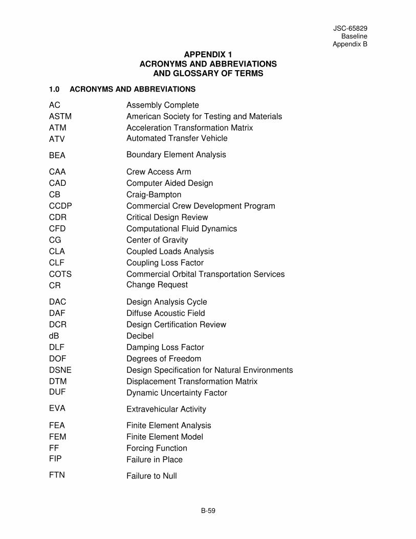
JSC-65829 Baseline
Appendix B
B-59
APPENDIX 1 ACRONYMS AND ABBREVIATIONS
AND GLOSSARY OF TERMS
1.0 ACRONYMS AND ABBREVIATIONS
AC Assembly Complete
ASTM American Society for Testing and Materials
ATM Acceleration Transformation Matrix
ATV Automated Transfer Vehicle
BEA Boundary Element Analysis
CAA Crew Access Arm
CAD Computer Aided Design
CB Craig-Bampton
CCDP Commercial Crew Development Program
CDR Critical Design Review
CFD Computational Fluid Dynamics
CG Center of Gravity
CLA Coupled Loads Analysis
CLF Coupling Loss Factor
COTS Commercial Orbital Transportation Services
CR Change Request
DAC Design Analysis Cycle
DAF Diffuse Acoustic Field
DCR Design Certification Review
dB Decibel
DLF Damping Loss Factor
DOF Degrees of Freedom
DSNE Design Specification for Natural Environments
DTM Displacement Transformation Matrix
DUF Dynamic Uncertainty Factor
EVA Extravehicular Activity
FEA Finite Element Analysis
FEM Finite Element Model
FF Forcing Function
FIP Failure in Place
FTN Failure to Null

JSC-65829 Baseline
Appendix B
B-60
g gravity
GFE Government-Furnished Equipment
GN&C Guidance, Navigation, & Control
GRAM Global Reference Atmospheric Model
GS Ground Systems
GSE Ground Support Equipment
GTA Ground Test Article
HO Hardover
HSIR Human-Systems Integration Requirements
HTV H-II Transfer Vehicle
ICD Interface Control Document
ID Identification
IEDS Induced Environments Design Specification
ISS International Space Station
IV&V Independent Verification and Validation
IVA Intravehicular Activity
LAS Launch Abort System
lbf pound force
lb pounds
LC Loads Cycle
L&D Loads and Dynamics
LDB Loads Data Book
LEO Low Earth Orbit
LIDS Low Impact Docking System
LIM Load Indicator Metric
LOI Lunar Orbit Insertion
LOX Liquid Oxygen
LSAM Lunar Surface Access Module
LSP Loads and Structures Panel
LTM Load Transformation Matrix
LV Launch Vehicle
LVP Launch Vehicle Provider
MAC Modal Assurance Criteria
MAF Michoud Assembly Facility
Max Q Maximum Dynamic Pressure
MECO Main Engine Cut-Off

JSC-65829 Baseline
Appendix B
B-61
MEFL Maximum Expected Flight Level
MEM Modal Effective Mass
ML Mobile Launcher
MPC Multi-Point Constraint
MPE Maximum Predicted Environment
MR Management Reserve
m/s meters per second
NASTRAN NASA Structural Analysis Program
OML Outer Mold Line
OPR Office of Primary Responsibility
OTM Over-Turning Moment
PDR Preliminary Design Review
PMP Program Management Plan
PSD Power Spectral Density
PTM Pressure Transformation Matrix
Q Dynamic Amplification Factor (when used in the context of shock response spectra)
Q Dynamic Pressure (when used in the context of atmospheric flight)
QA Quality Assurance
RCS Reaction Control System
RPODU Rendezvous, Proximity Operations, Docking and Undocking
RSS Root-Sum-Squared
SDR System Design Review
SDVR Structural Design and Verification Requirements
SE&I Systems Engineering and Integration
SEA Statistical Energy Analysis
SECB Systems Engineering Control Board
SI International System of Units/System Internationale
SM Service Module
SMI System Model Integrator
SC Spacecraft
SCP Spacecraft Provider
SPC Single Point Constraint
SPL Sound Pressure Level
SRD System Requirements Document
SRR System Requirements Review
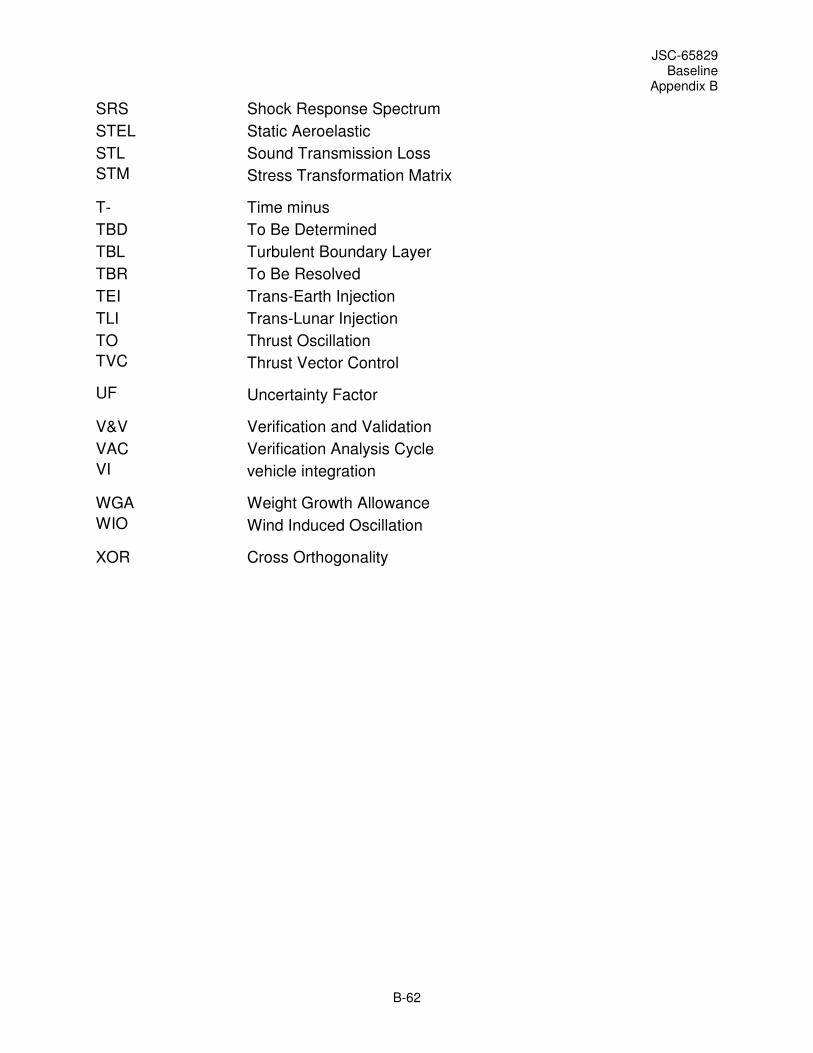
JSC-65829 Baseline
Appendix B
B-62
SRS Shock Response Spectrum
STEL Static Aeroelastic
STL Sound Transmission Loss
STM Stress Transformation Matrix
T- Time minus
TBD To Be Determined
TBL Turbulent Boundary Layer
TBR To Be Resolved
TEI Trans-Earth Injection
TLI Trans-Lunar Injection
TO Thrust Oscillation
TVC Thrust Vector Control
UF Uncertainty Factor
V&V Verification and Validation
VAC Verification Analysis Cycle
VI vehicle integration
WGA Weight Growth Allowance
WIO Wind Induced Oscillation
XOR Cross Orthogonality
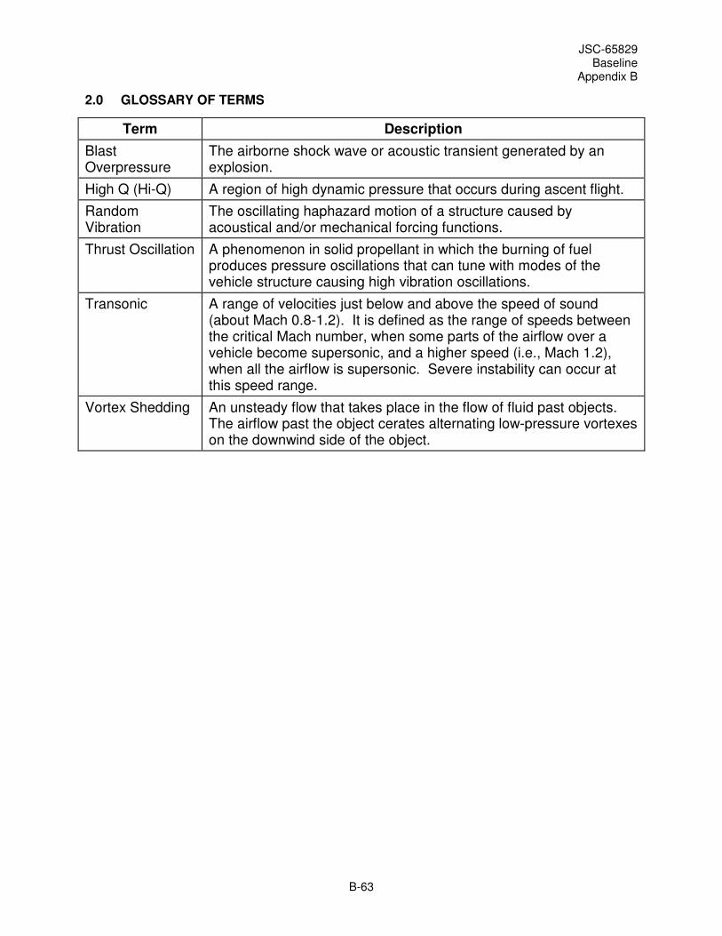
JSC-65829 Baseline
Appendix B
B-63
2.0 GLOSSARY OF TERMS
Term Description
Blast Overpressure
The airborne shock wave or acoustic transient generated by an explosion.
High Q (Hi-Q) A region of high dynamic pressure that occurs during ascent flight.
Random Vibration
The oscillating haphazard motion of a structure caused by acoustical and/or mechanical forcing functions.
Thrust Oscillation A phenomenon in solid propellant in which the burning of fuel produces pressure oscillations that can tune with modes of the vehicle structure causing high vibration oscillations.
Transonic A range of velocities just below and above the speed of sound (about Mach 0.8-1.2). It is defined as the range of speeds between the critical Mach number, when some parts of the airflow over a vehicle become supersonic, and a higher speed (i.e., Mach 1.2), when all the airflow is supersonic. Severe instability can occur at this speed range.
Vortex Shedding An unsteady flow that takes place in the flow of fluid past objects. The airflow past the object cerates alternating low-pressure vortexes on the downwind side of the object.

JSC-65829 Baseline
Appendix C
C-1
APPENDIX C <DELETED>
The contents of this Appendix have been deleted because SSP-50808 has been designated as an
applicable document for the Commercial Crew Transportation Services Program

JSC-65829 Baseline
Appendix D
D-1
APPENDIX D MODEL-RELATED REQUIREMENTS FROM THE SPACE STATION LOADS
CONTROL PLAN
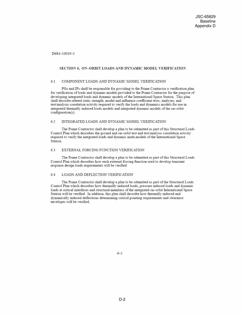
JSC-65829 Baseline
Appendix D
D-2
JSC-65829 Baseline
Appendix D
D-3

JSC-65829 Baseline
Appendix D
D-4
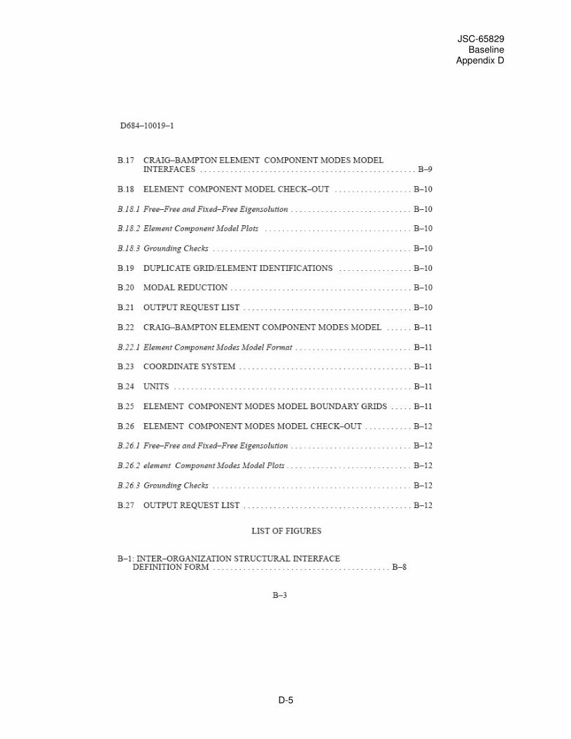
JSC-65829 Baseline
Appendix D
D-5

JSC-65829 Baseline
Appendix D
D-6
JSC-65829 Baseline
Appendix D
D-7

JSC-65829 Baseline
Appendix D
D-8
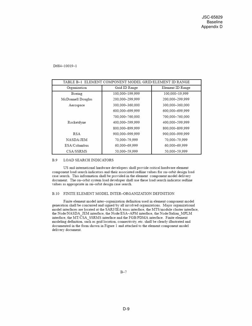
JSC-65829 Baseline
Appendix D
D-9

JSC-65829 Baseline
Appendix D
D-10

JSC-65829 Baseline
Appendix D
D-11
JSC-65829 Baseline
Appendix D
D-12

JSC-65829 Baseline
Appendix D
D-13
JSC-65829 Baseline
Appendix D
D-14
JSC-65829 Baseline
Appendix D
D-15