Embed Size (px)
Citation preview
JP 3GA 24.007(R99)
Mobile radio interface signalling layer 3;
General aspects
Version 2
October 25, 2000
THE TELECOMMUNICATION TECHNOLOGY COMMITTEE

i JP-3GA-24.007 (R99)
JP-3GA-24.007(R99)Mobile radio interface signalling layer 3;General aspects
Remarks
1.Application level of English descriptionApplication level:E3
English description is included in the text and figures of main body, annexes and appendices.
2.Relationship with international recommendations and standardsThis standard is standardized based on the Technical Specification 24.007 (Version 3.4.0) approved by 3GPP in
June 2000.
3.Departures from international recommendations3.1 Selection of optional items
None
3.2 Items of national matter
None
3.3 Changes to original standard
(1) Standards referred to in the original standard, which are replaced by TTC/ARIB standards.
Refer to Table 1.
(2) Items added to the original standard
None
(3) Items deleted from the original standard
None
(4) Items changed from the original standard
None
3.4 Difference in chapter ordering from the original standard.
There is no difference in chapter ordering from the original standard.
4.Change history
Revision Date Contents
V.1 Mar.31,2000 Newly standardized
V.2 Oct.25,2000 Revised based on the Technical Specification 24.007
(Version 3.4.0) approved by 3GPP
5.IPRThere is no specific description about IPR in this standard.
6.OthersNone
ii JP-3GA-24.007 (R99)
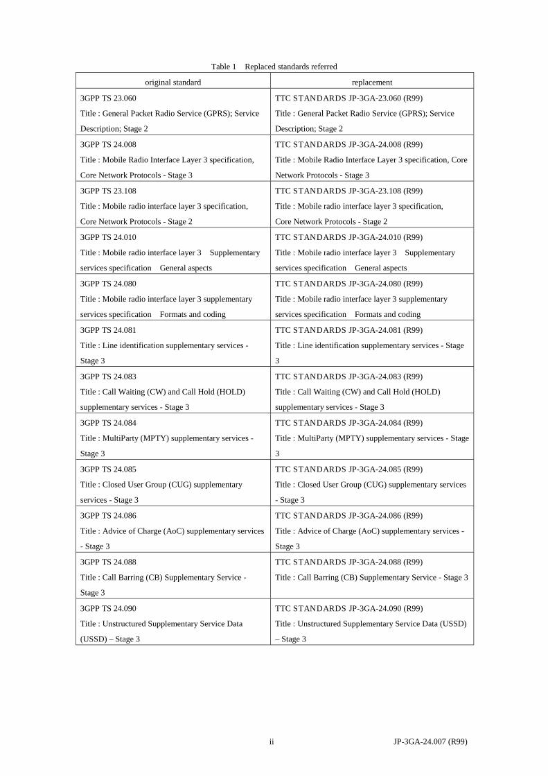
Table 1 Replaced standards referred
original standard replacement
3GPP TS 23.060
Title : General Packet Radio Service (GPRS); Service
Description; Stage 2
TTC STANDARDS JP-3GA-23.060 (R99)
Title : General Packet Radio Service (GPRS); Service
Description; Stage 2
3GPP TS 24.008
Title : Mobile Radio Interface Layer 3 specification,
Core Network Protocols - Stage 3
TTC STANDARDS JP-3GA-24.008 (R99)
Title : Mobile Radio Interface Layer 3 specification, Core
Network Protocols - Stage 3
3GPP TS 23.108
Title : Mobile radio interface layer 3 specification,
Core Network Protocols - Stage 2
TTC STANDARDS JP-3GA-23.108 (R99)
Title : Mobile radio interface layer 3 specification,
Core Network Protocols - Stage 2
3GPP TS 24.010
Title : Mobile radio interface layer 3 Supplementary
services specification General aspects
TTC STANDARDS JP-3GA-24.010 (R99)
Title : Mobile radio interface layer 3 Supplementary
services specification General aspects
3GPP TS 24.080
Title : Mobile radio interface layer 3 supplementary
services specification Formats and coding
TTC STANDARDS JP-3GA-24.080 (R99)
Title : Mobile radio interface layer 3 supplementary
services specification Formats and coding
3GPP TS 24.081
Title : Line identification supplementary services -
Stage 3
TTC STANDARDS JP-3GA-24.081 (R99)
Title : Line identification supplementary services - Stage
3
3GPP TS 24.083
Title : Call Waiting (CW) and Call Hold (HOLD)
supplementary services - Stage 3
TTC STANDARDS JP-3GA-24.083 (R99)
Title : Call Waiting (CW) and Call Hold (HOLD)
supplementary services - Stage 3
3GPP TS 24.084
Title : MultiParty (MPTY) supplementary services -
Stage 3
TTC STANDARDS JP-3GA-24.084 (R99)
Title : MultiParty (MPTY) supplementary services - Stage
3
3GPP TS 24.085
Title : Closed User Group (CUG) supplementary
services - Stage 3
TTC STANDARDS JP-3GA-24.085 (R99)
Title : Closed User Group (CUG) supplementary services
- Stage 3
3GPP TS 24.086
Title : Advice of Charge (AoC) supplementary services
- Stage 3
TTC STANDARDS JP-3GA-24.086 (R99)
Title : Advice of Charge (AoC) supplementary services -
Stage 3
3GPP TS 24.088
Title : Call Barring (CB) Supplementary Service -
Stage 3
TTC STANDARDS JP-3GA-24.088 (R99)
Title : Call Barring (CB) Supplementary Service - Stage 3
3GPP TS 24.090
Title : Unstructured Supplementary Service Data
(USSD) – Stage 3
TTC STANDARDS JP-3GA-24.090 (R99)
Title : Unstructured Supplementary Service Data (USSD)
– Stage 3

3G TS 24.007 V3.4.0 (2000-06)Technical Specification
3rd Generation Partnership Project;Technical Specification Group Core Network;
Mobile radio interface signalling layer 3;General aspects
(Release 1999)
The present document has been developed within the 3rd Generation Partnership Project (3GPP TM) and may be further elaborated for the purposes of 3GPP.The present document has not been subject to any approval process by the 3GPP Organisational Partners and shall not be implemented.This Specification is provided for future development work within 3GPP only. The Organisational Partners accept no liability for any use of this Specification.Specifications and reports for implementation of the 3GPP TM system should be obtained via the 3GPP Organisational Partners' Publications Offices.

3GPP
3G TS 24.007 V3.4.0 (2000-06)2Release 1999
Keywords3GPP, CN
3GPP
Postal address
3GPP support office address650 Route des Lucioles - Sophia Antipolis
Valbonne - FRANCETel.: +33 4 92 94 42 00 Fax: +33 4 93 65 47 16
Internethttp://www.3gpp.org
Copyright Notification
No part may be reproduced except as authorised by written permission.The copyright and the foregoing restrictions extend to reproduction in all media.
© 2000, 3GPP Organizational Partners (ARIB, CWTS, ETSI, T1, TTA,TTC).All rights reserved.

3GPP
3G TS 24.007 V3.4.0 (2000-06)3Release 1999
ContentsForeword ..........................................................................................................................................................11
1 Scope ......................................................................................................................................................11
2 References ..............................................................................................................................................12
3 Abbreviations .........................................................................................................................................13
4 Introduction ............................................................................................................................................134.1 General............................................................................................................................................................. 134.2 Applicability of functional blocks.................................................................................................................... 154.3 Technique of description.................................................................................................................................. 154.3.1 Service description ..................................................................................................................................... 154.3.2 Abstract service primitives......................................................................................................................... 154.3.3 Protocols and peer-to-peer communication................................................................................................ 164.3.4 Contents of layer 3 related Technical Specifications ................................................................................. 17
5 Structure of layer 3 functions .................................................................................................................175.1 Basic groups of functions................................................................................................................................. 175.2 Protocol architecture ........................................................................................................................................ 18
6 Services provided by signalling layer 3 at the MS side .........................................................................256.1 Registration services ........................................................................................................................................ 266.1.1 Service state diagram for MS not supporting GPRS service...................................................................... 266.1.2 Service primitives....................................................................................................................................... 266.1.2.1 MMR_REG_REQ ................................................................................................................................ 276.1.2.2 MMR_REG_CNF................................................................................................................................. 276.1.2.3 [reserved]............................................................................................................................................. 276.1.2.4 MMR_NREG_REQ.............................................................................................................................. 276.1.2.5 MMR_NREG_IND .............................................................................................................................. 276.1.3 Registration Services for CTS-Services ..................................................................................................... 276.1.3.1 MMR_CTS _ATTACH_REQ.............................................................................................................. 276.1.3.2 MMR_CTS _ATTACH_CNF .............................................................................................................. 276.1.3.3 MMR_CTS _ATTACH_REJ ............................................................................................................... 276.1.3.4 MMR_CTS _DETACH_IND............................................................................................................... 276.1.3.5 MMR_CTS _ENROLL_REQ .............................................................................................................. 286.1.3.6 MMR_CTS _ENROLL_CNF............................................................................................................... 286.1.3.7 MMR_CTS _ENROLL_REJ................................................................................................................ 286.1.3.8 MMR_CTS _DE_ENROLL_IND ........................................................................................................ 286.2 Call Control services........................................................................................................................................ 286.2.1 Service state diagram ................................................................................................................................. 286.2.2 Service primitives....................................................................................................................................... 316.2.2.1 MNCC_SETUP_REQ .......................................................................................................................... 316.2.2.2 MNCC_SETUP_IND ........................................................................................................................... 316.2.2.3 MNCC_SETUP_RES........................................................................................................................... 316.2.2.4 MNCC_SETUP_CNF .......................................................................................................................... 326.2.2.5 MNCC_SETUP_COMPL_REQ........................................................................................................... 326.2.2.6 MNCC_SETUP_COMPL_IND ........................................................................................................... 326.2.2.7 MNCC_REJ_REQ................................................................................................................................ 326.2.2.8 MNCC_REJ_IND................................................................................................................................. 326.2.2.9 MNCC_CALL_CONF_REQ ............................................................................................................... 326.2.2.10 MNCC_CALL_PROC_IND................................................................................................................. 326.2.2.11 MNCC_PROGRESS_IND ................................................................................................................... 326.2.2.12 MNCC_ALERT_REQ.......................................................................................................................... 326.2.2.13 MNCC_ALERT_IND .......................................................................................................................... 326.2.2.14 MNCC_NOTIFY_REQ........................................................................................................................ 326.2.2.15 MNCC_NOTIFY_IND......................................................................................................................... 326.2.2.16 MNCC_DISC_REQ ............................................................................................................................. 336.2.2.17 MNCC_DISC_IND .............................................................................................................................. 33
3GPP
3G TS 24.007 V3.4.0 (2000-06)4Release 1999
6.2.2.18 MNCC_REL_REQ............................................................................................................................... 336.2.2.19 MNCC_REL_IND................................................................................................................................ 336.2.2.20 MNCC_REL_CNF ............................................................................................................................... 336.2.2.21 MNCC_FACILITY_REQ .................................................................................................................... 336.2.2.22 MNCC_FACILITY_IND ..................................................................................................................... 336.2.2.23 MNCC_START_DTMF_REQ............................................................................................................. 336.2.2.24 MNCC_START_DTMF_CNF............................................................................................................. 336.2.2.25 MNCC_STOP_DTMF_REQ................................................................................................................ 336.2.2.26 MNCC_STOP_DTMF_CNF................................................................................................................ 336.2.2.27 MNCC_MODIFY_REQ....................................................................................................................... 336.2.2.28 MNCC_MODIFY_IND........................................................................................................................ 346.2.2.29 MNCC_MODIFY_RES ....................................................................................................................... 346.2.2.30 MNCC_MODIFY_CNF....................................................................................................................... 346.2.2.31 MNCC_SYNC_IND............................................................................................................................. 346.3 Call independent Supplementary Services Support ......................................................................................... 346.3.1 Service state diagram ................................................................................................................................. 346.3.2 Service primitives....................................................................................................................................... 356.3.2.1 MNSS_BEGIN_REQ ........................................................................................................................... 356.3.2.2 MNSS_BEGIN_IND............................................................................................................................ 356.3.2.3 MNSS_FACILITY_REQ ..................................................................................................................... 356.3.2.4 MNSS_FACILITY_IND...................................................................................................................... 356.3.2.5 MNSS_END_REQ ............................................................................................................................... 356.3.2.6 MNSS_END_IND................................................................................................................................ 356.4 Short Message Services Support...................................................................................................................... 356.5 Session Management Services for GPRS-Services.......................................................................................... 356.5.1 Session Management Services for SMREG-SAP ...................................................................................... 366.5.1.1 SMREG-PDP-ACTIVATE-REQ ......................................................................................................... 366.5.1.2 SMREG-PDP-ACTIVATE-CNF ......................................................................................................... 366.5.1.3 SMREG-PDP-ACTIVATE-REJ........................................................................................................... 366.5.1.4 SMREG-PDP-ACTIVATE-IND .......................................................................................................... 376.5.1.5 SMREG-PDP-DEACTIVATE-REQ.................................................................................................... 376.5.1.6 SMREG-PDP-DEACTIVATE-CNF .................................................................................................... 376.5.1.7 SMREG-PDP-DEACTIVATE-IND..................................................................................................... 376.5.1.8 SMREG-PDP-MODIFY-IND .............................................................................................................. 376.5.1.9 VOID.................................................................................................................................................... 376.5.1.10 VOID.................................................................................................................................................... 376.5.1.11 VOID.................................................................................................................................................... 376.5.1.12 VOID.................................................................................................................................................... 376.5.1.13 VOID.................................................................................................................................................... 376.5.1.14 SMREG-PDP-ACTIVATE-REJ-RSP .................................................................................................. 376.5.1.15 SMREG-PDP-ACTIVATE-SEC-REQ................................................................................................. 376.5.1.16 SMREG-PDP-ACTIVATE-SEC-CNF................................................................................................. 386.5.1.17 SMREG-PDP-ACTIVATE-SEC-REJ .................................................................................................. 386.5.1.18 SMREG-PDP-MODIFY-REQ ............................................................................................................. 386.5.1.19 SMREG-PDP-MODIFY-CNF.............................................................................................................. 386.5.1.20 SMREG-PDP-MODIFY-REJ............................................................................................................... 386.5.2 Session Management Services for SNSM-SAP ......................................................................................... 396.6 Registration Services for GPRS-Services ........................................................................................................ 396.6.1 Registration Services for GMMREG-SAP................................................................................................. 406.6.1.1 GMMREG-ATTACH-REQ ................................................................................................................. 406.6.1.2 GMMREG-ATTACH-CNF.................................................................................................................. 406.6.1.3 GMMREG-ATTACH-REJ................................................................................................................... 406.6.1.4 GMMREG-DETACH-REQ ................................................................................................................. 406.6.1.5 GMMREG-DETACH-CNF.................................................................................................................. 406.6.1.6 GMMREG-DETACH-IND .................................................................................................................. 406.7 Services provided to SNDCP entities by GPRS Logical Link Control services .............................................. 416.7.1 Service state diagram for QoS1-SAP, QoS2-SAP, QoS3-SAP and QoS4-SAP......................................... 426.7.2 Service primitives for QoS1-SAP, QoS2-SAP, QoS3-SAP and QoS4-SAP.............................................. 436.7.2.1 LL-ESTABLISH-REQ ......................................................................................................................... 436.7.2.2 LL-ESTABLISH-CNF ......................................................................................................................... 436.7.2.3 LL-ESTABLISH-IND.......................................................................................................................... 436.7.2.4 LL-ESTABLISH-RSP .......................................................................................................................... 43
3GPP
3G TS 24.007 V3.4.0 (2000-06)5Release 1999
6.7.2.5 LL-RELEASE-REQ ............................................................................................................................. 436.7.2.6 LL-RELEASE-CNF ............................................................................................................................. 446.7.2.7 LL-RELEASE-IND.............................................................................................................................. 446.7.2.8 LL-XID-REQ ....................................................................................................................................... 446.7.2.9 LL-XID-IND ........................................................................................................................................ 446.7.2.10 LL-XID-RSP ........................................................................................................................................ 446.7.2.11 LL-XID-CNF........................................................................................................................................ 446.7.2.12 LL-DATA-REQ.................................................................................................................................... 446.7.2.13 LL-DATA-CNF.................................................................................................................................... 446.7.2.14 LL-DATA-IND .................................................................................................................................... 446.7.2.15 LL-UNITDATA-REQ .......................................................................................................................... 446.7.2.16 LL-UNITDATA-IND........................................................................................................................... 446.7.2.17 LL-STATUS-IND ................................................................................................................................ 446.8 Location services at the MS side ..................................................................................................................... 446.8.1 Service state diagram ................................................................................................................................. 456.8.2 Service primitives....................................................................................................................................... 466.8.2.1 MNLCS_BEGIN_REQ ........................................................................................................................ 466.8.2.2 MNLCS_BEGIN_IND ......................................................................................................................... 466.8.2.3 MNLCS_FACILITY_REQ .................................................................................................................. 466.8.2.4 MNLCS_FACILITY_IND ................................................................................................................... 466.8.2.5 MNLCS_END_REQ ............................................................................................................................ 466.8.2.6 MNLCS_END_IND ............................................................................................................................. 46
7 Services provided by signalling layer 3 on the Network side ................................................................477.1 Call control services......................................................................................................................................... 477.1.1 Service state diagram ................................................................................................................................. 477.1.2 Service primitives....................................................................................................................................... 507.1.2.1 MNCC_SETUP_REQ .......................................................................................................................... 507.1.2.2 MNCC_SETUP_IND ........................................................................................................................... 507.1.2.3 MNCC_SETUP_RSP ........................................................................................................................... 507.1.2.4 MNCC_SETUP_CNF .......................................................................................................................... 517.1.2.5 MNCC_SETUP_COMPL_REQ........................................................................................................... 517.1.2.6 MNCC_SETUP_COMPL_IND ........................................................................................................... 517.1.2.7 MNCC_REJ_REQ................................................................................................................................ 517.1.2.8 MNCC_REJ_IND................................................................................................................................. 517.1.2.9 MNCC_CALL_CONF_IND ................................................................................................................ 517.1.2.10 MNCC_CALL_PROC_REQ................................................................................................................ 517.1.2.11 MNCC_PROGRESS_REQ .................................................................................................................. 517.1.2.12 MNCC_ALERT_REQ.......................................................................................................................... 517.1.2.13 MNCC_ALERT_IND .......................................................................................................................... 517.1.2.14 MNCC_NOTIFY_REQ........................................................................................................................ 517.1.2.15 MNCC_NOTIFY_IND......................................................................................................................... 517.1.2.16 MNCC_DISC_REQ ............................................................................................................................. 527.1.2.17 MNCC_DISC_IND .............................................................................................................................. 527.1.2.18 MNCC_REL_REQ............................................................................................................................... 527.1.2.19 MNCC_REL_IND................................................................................................................................ 527.1.2.20 MNCC_REL_CNF ............................................................................................................................... 527.1.2.21 MNCC_FACILITY_REQ .................................................................................................................... 527.1.2.22 MNCC_FACILITY_IND ..................................................................................................................... 527.1.2.23 MNCC_START_DTMF_IND.............................................................................................................. 527.1.2.24 MNCC_START_DTMF_RSP.............................................................................................................. 527.1.2.25 MNCC_STOP_DTMF_IND ................................................................................................................ 527.1.2.26 MNCC_STOP_DTMF_RSP ................................................................................................................ 527.1.2.27 MNCC_MODIFY_REQ....................................................................................................................... 527.1.2.28 MNCC_MODIFY_IND........................................................................................................................ 527.1.2.29 MNCC_MODIFY_RES ....................................................................................................................... 537.1.2.30 MNCC_MODIFY_CNF....................................................................................................................... 537.2 Call independent Supplementary Services Support ......................................................................................... 537.2.1 Service state diagram ................................................................................................................................. 537.2.2 Service primitives....................................................................................................................................... 547.2.2.1 MNSS_BEGIN_REQ ........................................................................................................................... 547.2.2.2 MNSS_BEGIN_IND............................................................................................................................ 54
3GPP
3G TS 24.007 V3.4.0 (2000-06)6Release 1999
7.2.2.3 MNSS_FACILITY_REQ ..................................................................................................................... 547.2.2.4 MNSS_FACILITY_IND...................................................................................................................... 547.2.2.5 MNSS_END_REQ ............................................................................................................................... 547.2.2.6 MNSS_END_IND................................................................................................................................ 547.3 Short Message Services Support...................................................................................................................... 547.4 Services provided to SNDCP and SMS entities by GPRS Logical Link Control services .............................. 547.4.1 Service state diagram for QoS1-SAP, QoS2-SAP, QoS3-SAP and QoS4-SAP......................................... 557.4.2 Service primitives for QoS1-SAP, QoS2-SAP, QoS3-SAP and QoS4-SAP.............................................. 557.4.2.1 LL-ESTABLISH-REQ ......................................................................................................................... 557.4.2.2 LL-ESTABLISH-CNF ......................................................................................................................... 557.4.2.3 LL-ESTABLISH-IND.......................................................................................................................... 557.4.2.4 LL-ESTABLISH-RSP .......................................................................................................................... 567.4.2.5 LL-RELEASE-REQ ............................................................................................................................. 567.4.2.6 LL-RELEASE-CNF ............................................................................................................................. 567.4.2.7 LL-RELEASE-IND.............................................................................................................................. 567.4.2.8 LL-XID-REQ ....................................................................................................................................... 567.4.2.9 LL-XID-IND ........................................................................................................................................ 567.4.2.10 LL-XID-RSP ........................................................................................................................................ 567.4.2.11 LL-XID-CNF........................................................................................................................................ 567.4.2.12 LL-DATA-REQ.................................................................................................................................... 567.4.2.13 LL-DATASENT-IND .......................................................................................................................... 567.4.2.14 LL-DATA-CNF.................................................................................................................................... 567.4.2.15 LL-DATA-IND .................................................................................................................................... 567.4.2.16 LL-UNITDATA-REQ .......................................................................................................................... 567.4.2.17 LL-UNITDATA-IND........................................................................................................................... 567.4.2.18 LL-STATUS-IND ................................................................................................................................ 577.5 Session Management Services for GPRS ........................................................................................................ 577.5.1 Session Management Services for SMREG-SAP ...................................................................................... 577.5.1.1 SMREG-PDP-ACTIVATE-REQ ......................................................................................................... 577.5.1.2 SMREG-PDP-ACTIVATE-REJ........................................................................................................... 577.5.1.3 SMREG-PDP-DEACTIVATE-REQ.................................................................................................... 577.5.1.4 SMREG-PDP-DEACTIVATE-CNF .................................................................................................... 577.5.1.5 SMREG-PDP-MODIFY-REQ ............................................................................................................. 587.5.1.6 SMREG-PDP-MODIFY-CNF.............................................................................................................. 587.5.1.7 SMREG-PDP-MODIFY-REJ............................................................................................................... 587.5.2 Session Management Services for SNSM-SAP ......................................................................................... 587.6 Location services at the Network side ............................................................................................................. 587.6.1 Service state diagram ................................................................................................................................. 587.6.2 Service primitives....................................................................................................................................... 597.6.2.1 MNLCS_BEGIN_REQ ........................................................................................................................ 597.6.2.2 MNLCS_BEGIN_IND ......................................................................................................................... 607.6.2.3 MNLCS_FACILITY_REQ .................................................................................................................. 607.6.2.4 MNLCS_FACILITY_IND ................................................................................................................... 607.6.2.5 MNLCS_END_REQ ............................................................................................................................ 607.6.2.6 MNLCS_END_IND ............................................................................................................................. 60
8 Services assumed from signalling layers 1 and 2...................................................................................608.1 Priority ............................................................................................................................................................. 608.2 Unacknowledged information transfer............................................................................................................. 608.3 Acknowledged information transfer ................................................................................................................ 608.4 Random access................................................................................................................................................. 618.5 Channel management and measurements ........................................................................................................ 61
9 Interlayer service interfaces on the MS side ..........................................................................................619.1 Services provided by the Radio Resource Management entity........................................................................ 619.1.1 Service state diagram ................................................................................................................................. 629.1.2 Service primitives....................................................................................................................................... 639.1.2.1 RR_EST_REQ...................................................................................................................................... 639.1.2.2 RR_EST_IND....................................................................................................................................... 639.1.2.3 RR_EST_CNF...................................................................................................................................... 639.1.2.4 RR_REL_IND ...................................................................................................................................... 639.1.2.5 RR_SYNC_IND ................................................................................................................................... 63
3GPP
3G TS 24.007 V3.4.0 (2000-06)7Release 1999
9.1.2.5a RR_INIT_REQ..................................................................................................................................... 649.1.2.5b RR_INIT_CONF .................................................................................................................................. 649.1.2.6 RR_DATA_REQ.................................................................................................................................. 649.1.2.7 RR_DATA_IND................................................................................................................................... 649.1.2.7a RR_FREL_REQ ................................................................................................................................... 649.1.2.8 RR_UNIT_DATA_IND ....................................................................................................................... 649.1.2.9 RR_ABORT_REQ ............................................................................................................................... 649.1.2.10 RR_ABORT_IND ................................................................................................................................ 659.1.3 Services provided by the Radio Resource Management entity for CTS .................................................... 659.1.3.1 CTS_RR_ALIVE_CHECK_IND ......................................................................................................... 659.2 Services provided by the Mobility Management entity ................................................................................... 659.2.1 Service state diagram ................................................................................................................................. 669.2.2 Service primitives....................................................................................................................................... 679.2.2.1 MMXX_EST_REQ .............................................................................................................................. 679.2.2.2 MMXX_EST_IND............................................................................................................................... 679.2.2.3 MMXX_EST_CNF .............................................................................................................................. 679.2.2.4 MMXX_REL_REQ.............................................................................................................................. 679.2.2.5 MMXX_REL_IND............................................................................................................................... 679.2.2.6 MMXX_DATA_REQ .......................................................................................................................... 689.2.2.7 MMXX_DATA_IND ........................................................................................................................... 689.2.2.8 MMXX_UNIT_DATA_REQ............................................................................................................... 689.2.2.9 MMXX_UNIT_DATA_IND................................................................................................................ 689.2.2.10 MMCC_SYNC_IND............................................................................................................................ 689.2.2.11 MMXX_REEST_REQ ......................................................................................................................... 689.2.2.12 MMXX_REEST_CNF ......................................................................................................................... 689.2.2.13 MMXX_ERR_IND .............................................................................................................................. 689.2.2.14 MMXX_PROMPT_IND ...................................................................................................................... 689.2.2.15 MMXX_PROMPT_REJ....................................................................................................................... 689.3 Services provided by radio resource management entity for GPRS services................................................... 699.3.1 Service primitives for GRR-SAP ............................................................................................................... 699.3.2 Service primitives for GMMRR-SAP ........................................................................................................ 699.3.2.1 GMMRR-ASSIGN-REQ...................................................................................................................... 699.3.2.2 GMMRR-PAGE-IND........................................................................................................................... 699.4 Services provided by the LLC entity for GPRS services ................................................................................. 699.4.1 Service primitives for LLGMM-SAP......................................................................................................... 699.4.1.1 LLGMM-ASSIGN-REQ ...................................................................................................................... 709.4.1.2 LLGMM-TRIGGER-REQ ................................................................................................................... 709.4.1.3 LLGMM-TRIGGER-IND .................................................................................................................... 709.4.1.4 LLGMM-SUSPEND-REQ................................................................................................................... 709.4.1.5 LLGMM-RESUME-REQ..................................................................................................................... 709.4.1.6 LLGMM-WINDOW-REQ ................................................................................................................... 709.4.1.7 LLGMM-WINDOW-CNF ................................................................................................................... 709.4.1.8 LL-UNITDATA-REQ .......................................................................................................................... 709.4.1.9 LL-UNITDATA-IND........................................................................................................................... 709.4.1.10 LLGMM-STATUS-IND ...................................................................................................................... 709.4.2 Service primitives for LLSMS-SAP........................................................................................................... 709.4.2.1 LL-UNITDATA-REQ .......................................................................................................................... 709.4.2.2 LL-UNITDATA-IND........................................................................................................................... 719.5 Services provided by the GMM for GPRS services......................................................................................... 719.5.1 Service primitives for GMMSM-SAP........................................................................................................ 719.5.1.1 GMMSM-ESTABLISH-REQ .............................................................................................................. 729.5.1.2 GMMSM-ESTABLISH-CNF............................................................................................................... 729.5.1.3 GMMSM-ESTABLISH-REJ................................................................................................................ 729.5.1.4 GMMSM-RELEASE-IND ................................................................................................................... 729.5.1.5 GMMSM-UNITDATA-REQ ............................................................................................................... 729.5.1.6 GMMSM-UNITDATA-IND ................................................................................................................ 729.5.2 Void............................................................................................................................................................ 729.5.3 Service primitives for GMMSMS-SAP...................................................................................................... 729.5.3.1 GMMSMS-REG-STATE-REQ............................................................................................................ 739.5.3.2 GMMSM- REG-STATE -RSP............................................................................................................. 739.5.4 Service primitives for PMMSMS-SAP ...................................................................................................... 739.5.4.1 PMMSMS_EST _REQ......................................................................................................................... 73
3GPP
3G TS 24.007 V3.4.0 (2000-06)8Release 1999
9.5.4.2 PMMSMS_EST _CNF......................................................................................................................... 739.5.4.3 PMMSMS_ERROR_IND .................................................................................................................... 739.5.4.4 PMMSMS_UNITDATA_REQ ............................................................................................................ 739.5.4.5 PMMSMS_UNITDATA_IND ............................................................................................................. 73
10 Interlayer service interfaces on the Network side ..................................................................................7410.1 Services provided by the Radio Resource Management entity........................................................................ 7410.1.1 Service state diagram ................................................................................................................................. 7410.1.2 Service primitives....................................................................................................................................... 7510.1.2.1 RR_EST_REQ...................................................................................................................................... 7510.1.2.2 RR_EST_IND....................................................................................................................................... 7610.1.2.3 RR_EST_CNF...................................................................................................................................... 7610.1.2.4 RR_REL_REQ ..................................................................................................................................... 7610.1.2.5 RR_REL_IND ...................................................................................................................................... 7610.1.2.6 RR_SYNC_REQ .................................................................................................................................. 7610.1.2.7 RR_SYNC_CNF .................................................................................................................................. 7610.1.2.8 RR_DATA_REQ.................................................................................................................................. 7610.1.2.9 RR_DATA_IND................................................................................................................................... 7610.1.2.10 RR_UNIT_DATA_REQ ...................................................................................................................... 7610.1.2.11 RR_UNIT_DATA_IND ....................................................................................................................... 7610.1.2.12 RR_ABORT_REQ ............................................................................................................................... 7610.1.2.13 RR_ABORT_IND ................................................................................................................................ 7610.2 Services provided by the Mobility Management entity ................................................................................... 7610.2.1 Service state diagram ................................................................................................................................. 7710.2.2 Service primitives....................................................................................................................................... 7810.2.2.1 MMXX_EST_REQ .............................................................................................................................. 7810.2.2.2 MMXX_EST_IND............................................................................................................................... 7810.2.2.3 MMXX_EST_CNF .............................................................................................................................. 7810.2.2.4 MMXX_REL_REQ.............................................................................................................................. 7810.2.2.5 MMXX_REL_IND............................................................................................................................... 7810.2.2.6 MMXX_DATA_REQ .......................................................................................................................... 7810.2.2.7 MMXX_DATA_IND ........................................................................................................................... 7810.2.2.8 MMXX_UNIT_DATA_REQ............................................................................................................... 7810.2.2.9 MMXX_UNIT_DATA_IND................................................................................................................ 7910.2.2.10 MMCC_SYNC_REQ ........................................................................................................................... 7910.2.2.11 MMCC_SYNC_CNF ........................................................................................................................... 7910.3 Services provided by radio resource management entity for GPRS services................................................... 7910.3.1 Service primitives for GRR-SAP ............................................................................................................... 7910.3.2 Service primitives for GMMRR-SAP ........................................................................................................ 7910.3.2.1 GMMRR-PAGE-REQ.......................................................................................................................... 7910.4 Services provided by the LLC entity for GPRS services ................................................................................. 8010.4.1 Service primitives for LLGMM-SAP......................................................................................................... 8010.4.1.1 LLGMM-ASSIGN-REQ ...................................................................................................................... 8010.4.1.2 LLGMM-TRIGGER-IND .................................................................................................................... 8010.4.1.3 LLGMM-SUSPEND-REQ................................................................................................................... 8010.4.1.4 LLGMM-RESUME-REQ..................................................................................................................... 8010.4.1.5 LLGMM-WINDOW-REQ ................................................................................................................... 8010.4.1.6 LLGMM-WINDOW-CNF ................................................................................................................... 8010.4.1.7 LLGMM-PAGE-IND ........................................................................................................................... 8110.4.1.8 LLGMM-PAGE-RESP-IND ................................................................................................................ 8110.4.1.9 LL-UNITDATA-REQ .......................................................................................................................... 8110.4.1.10 LL-UNITDATA-IND........................................................................................................................... 8110.4.1.11 LLGMM-STATUS-IND ...................................................................................................................... 8110.4.2 Service primitives for LLSMS-SAP........................................................................................................... 8110.4.2.1 LL-UNITDATA-REQ .......................................................................................................................... 8110.4.2.2 LL-UNITDATA-IND........................................................................................................................... 8110.5 Services provided by the GMM for GPRS services......................................................................................... 8110.5.1 Service primitives for GMMSM-SAP........................................................................................................ 8110.5.1.1 GMMSM-RELEASE-IND ................................................................................................................... 8210.5.1.2 GMMSM-UNITDATA-REQ ............................................................................................................... 8210.5.1.3 GMMSM-UNITDATA-IND ................................................................................................................ 8210.5.2 Service primitives for PMMSMS-SAP ...................................................................................................... 82
3GPP
3G TS 24.007 V3.4.0 (2000-06)9Release 1999
10.5.2.1 PMMSMS_REL_REQ ......................................................................................................................... 8210.5.2.2 PMMSMS_ERROR_IND .................................................................................................................... 8210.5.2.3 PMMSMS_UNITDATA_REQ ............................................................................................................ 8210.5.2.4 PMMSMS_UNITDATA_IND ............................................................................................................. 8210.6 Services provided by the Radio Resource Management entity for CTS on the fixed part............................... 8210.6.1 Service primitives....................................................................................................................................... 8310.6.1.1 RR_ CTS_ALIVE_CHECK_REQ ....................................................................................................... 8310.6.1.2 RR_ CTS_ALIVE_CHECK_IND ........................................................................................................ 8310.6.1.3 RR_ CTS_HUNTING_REQ ................................................................................................................ 8310.6.1.4 RR_ CTS_GROUP_ALERTING_REQ ............................................................................................... 83
11 L3 Messages...........................................................................................................................................8311.1 General............................................................................................................................................................. 8311.1.1 Messages .................................................................................................................................................... 8311.1.2 Octets ......................................................................................................................................................... 8511.1.3 Integer ........................................................................................................................................................ 8511.1.3.1 Binary ................................................................................................................................................... 8511.1.3.2 2-complement binary............................................................................................................................ 8611.1.4 Spare parts.................................................................................................................................................. 8611.2 Standard L3 messages...................................................................................................................................... 8611.2.1 Components of a standard L3 message ...................................................................................................... 8611.2.1.1 Format of standard information elements............................................................................................. 8611.2.1.1.1 Information element type and value part ........................................................................................ 8711.2.1.1.2 Length indicator .............................................................................................................................. 8711.2.1.1.3 Information element identifier ........................................................................................................ 8711.2.1.1.4 Categories of IEs; order of occurrence of IEI, LI, and value part ................................................... 8711.2.2 Description methods for IE structure ......................................................................................................... 8911.2.2.1 Tables ................................................................................................................................................... 8911.2.2.1.1 Compact notation ............................................................................................................................ 9011.2.3 Imperative part of a standard L3 message .................................................................................................. 9011.2.3.1 Header .................................................................................................................................................. 9011.2.3.1.1 Protocol discriminator..................................................................................................................... 9011.2.3.1.2 Skip indicator .................................................................................................................................. 9011.2.3.1.3 Transaction identifier ...................................................................................................................... 9111.2.3.1.4 Sub-protocol discriminator ............................................................................................................. 9211.2.3.2 Message type octet................................................................................................................................ 9211.2.3.2.1 Message type octet (when accessing Release 98 and older networks only).................................... 9211.2.3.2.2 Message type octet (when accessing Release 99 and newer networks) .......................................... 9311.2.3.3 Standard information elements of the imperative part.......................................................................... 9411.2.4 Non-imperative part of a standard L3 message .......................................................................................... 9411.2.5 Presence requirements of information elements......................................................................................... 9511.2.6 Description of standard L3 messages ......................................................................................................... 9611.3 Non standard L3 messages............................................................................................................................... 9611.3.1 Case A : BCCH and AGCH/PCH messages .............................................................................................. 9611.3.1.1 L2 Pseudo Length octet ........................................................................................................................ 9611.3.1.2 Rest Octets............................................................................................................................................ 9711.3.1.3 Description of a modified standard L3 message................................................................................... 9711.3.2 Case B : SACCH messages sent in unacknowledged mode....................................................................... 9711.3.2.1 The first octet........................................................................................................................................ 9711.3.2.2 The rest of the message ........................................................................................................................ 9711.3.3 Design guidelines for non standard parts ................................................................................................... 9711.3.3.1 General ................................................................................................................................................. 9711.4 Handling of superfluous information............................................................................................................... 9811.4.1 Information elements that are unnecessary in a message ........................................................................... 9811.4.2 Other syntactic errors ................................................................................................................................. 98
Annex A (informative): MN-Services arrow diagram ........................................................................99
Annex B (informative): Description of CSN.1 ...................................................................................107B.1 The Basic Rules....................................................................................................................................107B.1.1 Core Rules ..................................................................................................................................................... 107B.1.1.1 Rule B1: Bits ............................................................................................................................................ 107

3GPP
3G TS 24.007 V3.4.0 (2000-06)10Release 1999
B.1.1.2 Rule B2: Null String................................................................................................................................. 107B.1.1.3 Rule B3: Concatenation ........................................................................................................................... 108B.1.1.4 Rule B4: Choice ....................................................................................................................................... 108B.1.1.5 Rule B5: Naming...................................................................................................................................... 109B.1.1.6 Rule B6: Definition .................................................................................................................................. 109B.1.2 Spare parts ..................................................................................................................................................... 109B.1.2.1 Rule B7: Spare bits................................................................................................................................... 110B.1.2.2 Rule B8: Padding bits............................................................................................................................... 110B.1.3 Predefined sets ............................................................................................................................................... 110B.1.4 Labelling Parts ............................................................................................................................................... 111B.1.4.1 Rule A1: Labels........................................................................................................................................ 111B.1.5 Goodies.......................................................................................................................................................... 111B.1.5.1 Rule G1: Comments ................................................................................................................................. 111
B.2 Advanced rules.....................................................................................................................................111B.2.1 Rule A2: Exponent notation........................................................................................................................... 111
Annex C (informative): GPRS-Services sequence diagram..............................................................113
Annex D (informative): Change history .............................................................................................132
3GPP
3G TS 24.007 V3.4.0 (2000-06)11Release 1999
ForewordThis Technical Specification (TS) has been produced by the 3rd Generation Partnership Project (3GPP).
The present document defines the architecture of layer 3 and its sublayers on the GSM Um interface, i.e. the interfacebetween Mobile Station and network within the 3GPP system.
The contents of the present document are subject to continuing work within the TSG and may change following formalTSG approval. Should the TSG modify the contents of the present document, it will be re-released by the TSG with anidentifying change of release date and an increase in version number as follows:
Version x.y.z
where:
x the first digit:
1 presented to TSG for information;
2 presented to TSG for approval;
3 or greater indicates TSG approved document under change control.
y the second digit is incremented for all changes of substance, i.e. technical enhancements, corrections, updates,etc.
z the third digit is incremented when editorial only changes have been incorporated in the document.
1 ScopeThe present document defines the principal architecture of layer 3 and its sublayers on the GSM Um interface, i.e. theinterface between Mobile Station (MS) and network; for the CM sublayer, the description is restricted to paradigmaticexamples, call control, supplementary services, and short message services for non-GPRS services. It also defines thebasic message format and error handling applied by the layer 3 protocols.
For CTS services, the present document defines the principal architecture of layer 3 on the GSM Um* interface, i.e. theinterface between a CTS capable Mobile Station (CTS-MS) and a Fixed Part (FP).
The corresponding protocols are defined in other Technical Specifications, see subclause 4.3.4.
For non-GPRS services the communication between sublayers and adjacent layers and the services provided by thesublayers are distributed by use of abstract service primitives. But only externally observable behaviour resulting fromthe description is normatively prescribed by the present document.
For GPRS services in addition the local information transfer and stimuli sent between sublayers is informativelyincluded within Annex C of in the present document.
3GPP
3G TS 24.007 V3.4.0 (2000-06)12Release 1999
2 ReferencesThe following documents contain provisions which, through reference in this text, constitute provisions of the presentdocument.
• References are either specific (identified by date of publication, edition number, version number, etc.) ornon-specific.
• For a specific reference, subsequent revisions do not apply.
• For a non-specific reference, the latest version applies.
[1] GSM 01.02: "Digital cellular telecommunications system (Phase 2+); General description of aGSM Public Land Mobile Network (PLMN)".
[1a] TS 21.905: "Vocabulary for 3GPP Specifications".
[2] GSM 03.01: "Digital cellular telecommunications system (Phase 2+); Network functions".
[3a] TS 23.060: "General Packet Radio Service (GPRS) Description; Stage 2".
[3b] GSM 03.56: "Digital cellular telecommunications system (Phase 2+); GSM Cordless TelephonySystem (CTS), phase 1; CTS Architecture Description; Stage 2".
[3] GSM 04.01: "Digital cellular telecommunications system (Phase 2+); Mobile Station - BaseStation System (MS - BSS) interface General aspects and principles".
[3b] GSM 03.71: "Digital cellular telecommunications system (Phase 2+); Location Services (LCS)Functional Description; Stage 2".
[4] GSM 04.05: "Digital cellular telecommunications system (Phase 2+); Data Link (DL) layerGeneral aspects".
[5] GSM 04.06: "Digital cellular telecommunications system (Phase 2+); Mobile Station - BaseStation System (MS - BSS) interface Data Link (DL) layer specification".
[6] TS 24.008: "Mobile radio interface layer 3 specification Core Network Protocols-Stage 3".
[6a] TS 23.108: "Mobile Radio Interface Layer 3 specification Core Network Protocols stage 2(structured procedures)".
[7] TS 24.010: "Mobile radio interface layer 3 Supplementary services specification General aspects".
[8a] GSM 04.71: "Digital cellular telecommunications system (Phase 2+); Mobile radio interface layer3 specification; Location Services (LCS)".
[8] TS 24.011: "Point-to-Point (PP) Short Message Service (SMS) support on mobile radio interface".
[9] TS 24.080: "Mobile radio interface layer 3 supplementary services specification Formats andcoding".
[10] TS 24.081: "Line identification supplementary services - Stage 3".
[10a] GSM 04.60: "Digital cellular telecommunications system (Phase 2+);General Packet Radio Services (GPRS); Mobile Station (MS) - Base Station System (BSS)interface; Radio Link Control and medium Access Control (RLS/MAC) layer specification".
[10b] GSM 04.56: "Digital cellular telecommunications system (Phase 2+);GSM Cordless Telephony System (CTS), phase 1; CTS Radio Interface Layer 3 specification".
[11] TS 24.82: "Call Forwarding (CF) supplementary services - Stage 3".
[11a] GSM 04.64: "Digital cellular telecommunications system (Phase 2+); Mobile Station - GPRSsupport node (MS-SGSN) Logical Link Control Layer Specification".
[12] TS 24.083: "Call Waiting (CW) and Call Hold (HOLD) supplementary services - Stage 3".
3GPP
3G TS 24.007 V3.4.0 (2000-06)13Release 1999
[12a] GSM 04.65: "Digital cellular telecommunications system (Phase 2+); General Packet RadioService (GPRS); Mobile Station (MS) - Serving GPRS Support Node (SGSN); SubnetworkDependent Convergence Protocol (SNDCP)".
[13] TS 24.084: "MultiParty (MPTY) supplementary services - Stage 3".
[14] TS 24.085: "Closed User Group (CUG) supplementary services - Stage 3".
[15] TS 24.086: "Advice of Charge (AoC) supplementary services - Stage 3".
[16] TS 24.088: "Call Barring (CB) supplementary services - Stage 3".
[17] TS 24.090: "Unstructured supplementary services operation - Stage 3".
[18] ITU-T Recommendation X.200: "Reference Model of Open systems interconnection for ITU-TApplications".
3 AbbreviationsAbbreviations used in the present document, are listed in GSM 01.04.
For the purposes of the present document, the following abbreviations apply:
GMM GPRS Mobility ManagementMNS Mobile Network SignallingN-PDU Network Protocol Data UnitSM Session ManagementUDT User Data TransferCTS Cordless Telephony SystemLCS Location Services
4 Introduction
4.1 GeneralThree models are defined for Layer 3, one model for non-GPRS services, one for GPRS services supporting Class CMSs only and one model for GPRS-services supporting Class A and Class B MSs. (The third model is a combination ofthe first two models listed).
The layer 3 for non-GPRS services provides the functions necessary:
- for Radio Resource (RR) management;
- for Mobility Management (MM); and
- for the Connection Management (CM) functions, i.e. functions for the control, provision, and support of servicesoffered by the network; among which there are, e.g.:
- the functions to establish, maintain and terminate circuit-switched connections across a GSM PLMN andother networks to which the GSM PLMN is connected;
- supporting functions for supplementary services control;
- supporting functions for short messages service control;
- supporting functions for location services control.
3GPP
3G TS 24.007 V3.4.0 (2000-06)14Release 1999
The layer 3 for non-GPRS services is composed of three sublayers comprising:
- the Radio Resource Management (RR) functions;
- the Mobility Management (MM) functions; and
- the Connection Management (CM) functions.
When CTS services are added to non-GPRS services, the following functions are added:
- CTS Radio Resource Management (CTS-RR) functions to RR; and
- CTS Mobility Management (CTS-MM) functions to MM.
The layer 3 for GPRS services is composed of four sublayers comprising:
- the Radio Resource Management (RR) functions;
- the Mobility Management (GMM);
- for the Logical Link Control (LLC);
- the Connection Management (CM) functions;
- Session Management (SM) functions to activate, modify and delete the contexts for packet data protocols (PDP);
- supporting functions for short messages service control.
The Connection Management (CM) sublayer is composed of functional blocks for:
- Call Control (CC) for non-GPRS services;
- Short Message Service Support (SMS) for non-GPRS services;
- GPRS Short Message Service Support (GSMS) (for GPRS services supporting Class A, B and C MSs);
- Session Management (SM) (for GPRS services supporting Class A, B and C MSs);
- Supplementary Services Support (SS) for non-GPRS services;
- Group Call Control for non-GPRS services;
- Broadcast Call Control (BCC) for non-GPRS services;
- Connection Management of Packet Data on Signalling channels for non-GPRS services.
- Location Services support (LCS) for non-GPRS services.
Within the context of LCS, for GSM LCS, the services defined for an MS are equally applicable to a type A LMU,unless otherwise stated. The following is a list of services essential for a type A LMU.
The layer 3 for non-GPRS services provides the functions necessary:
- for Radio Resource (RR) management;
- for Mobility Management (MM); and
- supporting functions for location service control.
The layer 3 for non-GPRS services is composed of three sublayers comprising:
- the Radio Resource Management (RR) functions;
- the Mobility Management (MM) functions; and
- the Connection Management (CM) functions.

3GPP
3G TS 24.007 V3.4.0 (2000-06)15Release 1999
The Connection Management (CM) sublayer is composed of functional block for:
- location services support (LCS) for non-GPRS services.
The present document does not consider the distribution of signalling functions among the different networkequipments. The signalling functions are described between two systems which represent the MS side and the networkside of the radio interface of layer 3. Only the functions in the network for signalling communication with one MS isconsidered.
For GPRS services, in addition to the signalling functions also the user data transfer is included in this TechnicalSpecification.
4.2 Applicability of functional blocksNot for all functional blocks listed in subclause 4.1, support in the MS or in the network is mandatory:
- Support of Group Call Control is optional in the MS and in the network.
- Support of Broadcast Call Control is optional in the MS and in the network.
- Connection Management of Packet Data on Signalling channels. is optional in the MS and in the network.
- Support of GPRS services is optional in the MS and in the network.
- Support of CTS services is optional in the MS. CTS services are not applicable to the network.
- Support of LCS services is optional in the MS and in the network, but not optional in LMU.
Further conditions and constraints are defined in other Technical Specifications.
4.3 Technique of descriptionLayer 3 and its sub-layers are specified by:
- their service specification, see subclause 4.3.1;
- their protocol specification, see subclause 4.3.3;
- the specification of functions, see clause 5.
4.3.1 Service descriptionThe services of signalling layer 3 and its sublayers are described in terms of:
- services provided to upper (sub-)layers at the service access points;
- services assumed from lower (sub-)layers at the service access points.
Layer 3 and its supporting lower layers provide the Mobile Network Signalling (MNS) Service and User Data Transfer(UDT) Service (for GPRS services only) to the upper layers.
The service provided/assumed at the service access points are described by means of abstract service primitives andparameters as recommended in ITU-T Recommendation X.200.
4.3.2 Abstract service primitivesThe abstract service primitives consist of requests, responses, indications and confirmations. The general syntax of aprimitive is specified in TS 21.905.

3GPP
3G TS 24.007 V3.4.0 (2000-06)16Release 1999
4.3.3 Protocols and peer-to-peer communicationBy use of the services provided by lower (sub-)layers, peer entities in a (sub-)layer in the MS and the network exchangeinformation. Exchange of information between two peer entities is performed according to thecorresponding (sub-)layer protocols. A protocol is a set of rules and formats by which the information (controlinformation and user data) is exchanged between the two peers. The information is exchanged by use of messageswhich are defined in the protocol. (Therefore, the messages are also called Protocol Data Units, PDUs).
There are several protocols of the RR sublayer, one protocol of the LLC sublayer, three protocols of the MM sublayer,and several protocols of the CM sublayer. For each functional block of the CM sublayer as defined in subclause 4.1there is one protocol. The CM protocols are specified in the Technical Specifications identified in subclause 4.3.4.
In the model used in this specification, there is:
1) for non-GPRS services:
- one RR sub-layer entity in the MS and one RR sub-layer entity in the network;
- one MM sub-layer entity in the MS and one MM sub-layer entity in the network;
for each functional block of the CM sublayer as defined in subclause 4.1 which is supported in the MS (in thenetwork), there are, depending on the protocol, one or more entities in the MS (in the network). Two differententities of the same functional block in the MS (in the network) are called parallel entities. The entities of thesame functional block in the MS correspond in a one-to-one relation to the entities of the functional block in thenetwork. The corresponding entities are called peer entities;
2) for CTS services (in addition to non-GPRS services):
- one RR sub-layer entity in the MS and one in the CTS fixed part. These RR sub-layers include one CTS-RR sub-entity on each side;
- one MM sub-layer entity in the MS and one in the CTS fixed part These MM sub-layers include one CTS-MMsub-entity on each side;
- for each functional block of the CM sublayer as defined in subclause 4.1 which is supported in the MS (in thefixed part), there are, depending on the protocol, one or more entities in the MS (in the fixed part). Two differententities of the same functional block in the MS (in the fixed part) are called parallel entities. The entities of thesame functional block in the MS correspond in a one-to-one relation to the entities of the functional block in thefixed part. The corresponding entities are called peer entities;
3) for GPRS services supporting Class C MSs:
- one RR sublayer entity (RR) in the MS and one RR sublayer entity in the network;
- six LLC sublayer entities (QoS1-QoS4, signalling, SMS) in the MS and six LLC sublayer entities in thenetwork;
- one MM sublayer entity (GMM) in the MS and one MM sublayer entity in the network (GMM);
- one SM entity in the MS�s CM sublayer and one SM sublayer entity in the network�s CM sublayer;
- one or more GSMS functional blocks in the CM sublayer if supported;
4) for non-GPRS and GPRS services supporting Class A and Class B MSs:
- two RR sublayer entities (RR) in the MS and two RR sublayer entities in the network;
- six LLC sublayer entities (QoS1-QoS4, signalling, SMS) in the MS and six LLC sublayer entities in thenetwork;
- two MM sublayer entities (GMM + MM) in the MS and one or two MM sublayer entities in the network(GMM or MM);
- one SM entity in the MS�s CM sublayer and one SM entity in the network�s CM sublayer;
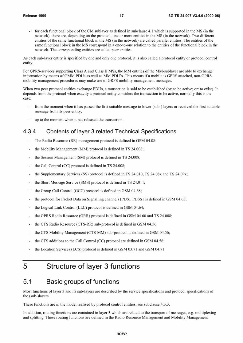
3GPP
3G TS 24.007 V3.4.0 (2000-06)17Release 1999
- for each functional block of the CM sublayer as defined in subclause 4.1 which is supported in the MS (in thenetwork), there are, depending on the protocol, one or more entities in the MS (in the network). Two differententities of the same functional block in the MS (in the network) are called parallel entities. The entities of thesame functional block in the MS correspond in a one-to-one relation to the entities of the functional block in thenetwork. The corresponding entities are called peer entities.
As each sub-layer entity is specified by one and only one protocol, it is also called a protocol entity or protocol controlentity.
For GPRS-services supporting Class A and Class B MSs, the MM entities of the MM-sublayer are able to exchangeinformation by means of GMM PDUs as well as MM PDU�s. This means if a mobile is GPRS attached, non-GPRSmobility management procedures may make use of GRPS mobility management messages.
When two peer protocol entities exchange PDUs, a transaction is said to be established (or: to be active; or: to exist). Itdepends from the protocol when exactly a protocol entity considers the transaction to be active, normally this is thecase:
- from the moment when it has passed the first suitable message to lower (sub-) layers or received the first suitablemessage from its peer entity;
- up to the moment when it has released the transaction.
4.3.4 Contents of layer 3 related Technical Specifications- The Radio Resource (RR) management protocol is defined in GSM 04.08:
- the Mobility Management (MM) protocol is defined in TS 24.008;
- the Session Management (SM) protocol is defined in TS 24.008;
- the Call Control (CC) protocol is defined in TS 24.008;
- the Supplementary Services (SS) protocol is defined in TS 24.010, TS 24.08x and TS 24.09x;
- the Short Message Service (SMS) protocol is defined in TS 24.011;
- the Group Call Control (GCC) protocol is defined in GSM 04.68;
- the protocol for Packet Data on Signalling channels (PDS), PDSS1 is defined in GSM 04.63;
- the Logical Link Control (LLC) protocol is defined in GSM 04.64;
- the GPRS Radio Resource (GRR) protocol is defined in GSM 04.60 and TS 24.008;
- the CTS Radio Resource (CTS-RR) sub-protocol is defined in GSM 04.56;
- the CTS Mobility Management (CTS-MM) sub-protocol is defined in GSM 04.56;
- the CTS additions to the Call Control (CC) protocol are defined in GSM 04.56;
- the Location Services (LCS) protocol is defined in GSM 03.71 and GSM 04.71.
5 Structure of layer 3 functions
5.1 Basic groups of functionsMost functions of layer 3 and its sub-layers are described by the service specifications and protocol specifications ofthe (sub-)layers.
These functions are in the model realised by protocol control entities, see subclause 4.3.3.
In addition, routing functions are contained in layer 3 which are related to the transport of messages, e.g. multiplexingand splitting. These routing functions are defined in the Radio Resource Management and Mobility Management

3GPP
3G TS 24.007 V3.4.0 (2000-06)18Release 1999
sub-layers.
1) They have the task to pass the messages from upper (sub-)layers to lower (sub-)layers.
2) They also have the task to pass messages provided by lower (sub-layers) to the appropriate sub-layer and, ifapplicable, entity.
The routing functions with task 2 make use of the protocol discriminator (PD) which is part of the message header.
A CM sublayer protocol may also define a transaction identifier (TI) as a part of the message header. This is at least thecase if there are parallel entities of the same functional block, see subclause 4.3.3. If it is a part of a message, the TI isalso used by the routing functions.
- The MM-sublayer routing function passes the messages of the CM entities as well as of the MM, GMM andCTS-MM entities of its own sublayer to the service access point of RR, GRR, LLC or CTS-RR. Furthermore itmultiplexes them in case of parallel transactions.
- The routing function of Radio Resource Management distributes the messages to be sent according to theirmessage type and protocol discriminator (PD), to the actual channel configuration, and, if applicable, to furtherinformation received from upper sub-layers to the appropriate service access point of layer 2 (identified by SAPIand logical channel). Paging messages received from the PPCH are always routed to GMM, while pagingmessages received from the PCH are distributed to GMM or MM based on the temporary identifier (TMSI orTLL).
- The messages provided at the different service access points of layer 2 are distributed by the RR sublayer routingfunction according to their protocol discriminator (PD). Messages with a PD equal to RR are passed to the RRentity of the own sublayer, all other messages are passed to the MM sublayer at the service access point RR-SAP.
- The routing function of MM-sublayer passes Standard L3 messages according to the protocol discriminator (PD)and, if applicable, the transaction identifier (TI) or the PDP address towards the MM entity or towards the CMentities via the various MM-SAP's. GPRS L3 messages are routed to mobility management or sessionmanagement according to the protocol discriminator.
- The routing function of LLC passes the messages according to the SAPIs to the MM sublayer or to the SNDCPentities.
The message (message header or other parts of the message) are neither changed nor removed by the RR routingfunction or MM routing function before passing it to the appropriate service access point.
5.2 Protocol architectureThe protocol architecture is visualised for each of the three models:
- Figure 5.1/TS 24.007 shows the protocol architecture for a MS not supporting the GPRS service, restricting therepresentation of CM sublayer protocols to four paradigmatic examples, CC, LCS, SS, and SMS. Note that theprotocol stack for a class C GPRS service may be present in the MS, but it is not active simultaneously.
- Figure 5.2 shows the protocol architecture for a MS supporting the Class C GPRS service. (Note that theprotocol stack for a circuit switched services may be present in the MS, but it is not active simultaneously).
- Figure 5.3 shows the protocol architecture for non-GPRS and GPRS-services supporting Class A and Class BMSs.
- Figure 5.4 shows the protocol architecture for a MS supporting CTS services in addition to non-GPRS services.
- Figure 5.5 shows the protocol architecture for a MS supporting the PS mode of operation UMTS service.
- Figure 5.6 shows the protocol architecture for UMTS services supporting CS/PS mode of operation MSs.
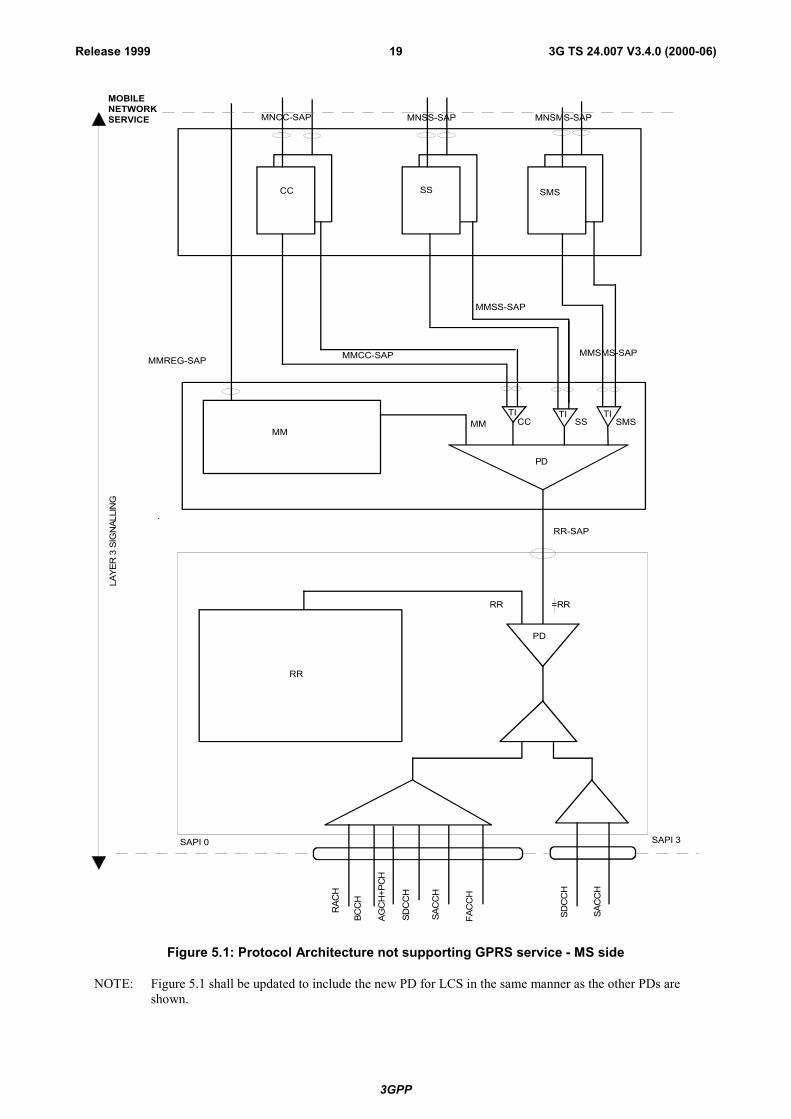
3GPP
3G TS 24.007 V3.4.0 (2000-06)19Release 1999
RAC
H
AGC
H+P
CH
SAC
CH
FAC
CH
SDC
CH
SAPI 0 SAPI 3
RR
MM
PD
MM CC SS SMS
MMREG-SAP MMCC-SAP
MMSS-SAP
MMSMS-SAP
CC SS SMS
MOBILENETWORKSERVICE MNCC-SAP MNSS-SAP MNSMS-SAP
BCC
H
SDC
CH
SAC
CH
RR-SAP
RR
LAYE
R 3
SIG
NAL
LIN
G
=RR
TI TI TI
PD
Figure 5.1: Protocol Architecture not supporting GPRS service - MS side
NOTE: Figure 5.1 shall be updated to include the new PD for LCS in the same manner as the other PDs areshown.
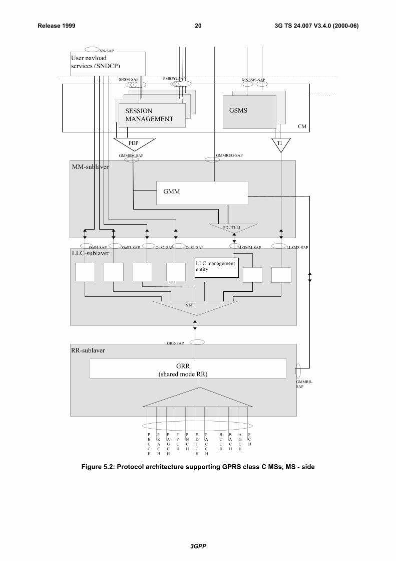
3GPP
3G TS 24.007 V3.4.0 (2000-06)20Release 1999
PDP
LLC-sublayer
RR-sublayer
MM-sublayer
GRR-SAP
PRACH
PPCH
PAGCH
PBCCH
PDTCH
PACCH
SAPI
QoS1-SAPQoS2-SAPQoS3-SAPQoS4-SAP
GSMS
MNSMS-SAP
GRR(shared mode RR)
LLSMS-SAP
LLC managemententity
LLGMM-SAP
GMMSM-SAP
GMMRR-SAP
SESSION MANAGEMENT
RACH
PCH
AGCH
BCCH
PNCH
TI
GMMREG-SAP
CM
PD / TLLI
GMM
SNSM-SAP SMREG-SAP
SN-SAP
services (SNDCP)User payload
Figure 5.2: Protocol architecture supporting GPRS class C MSs, MS - side
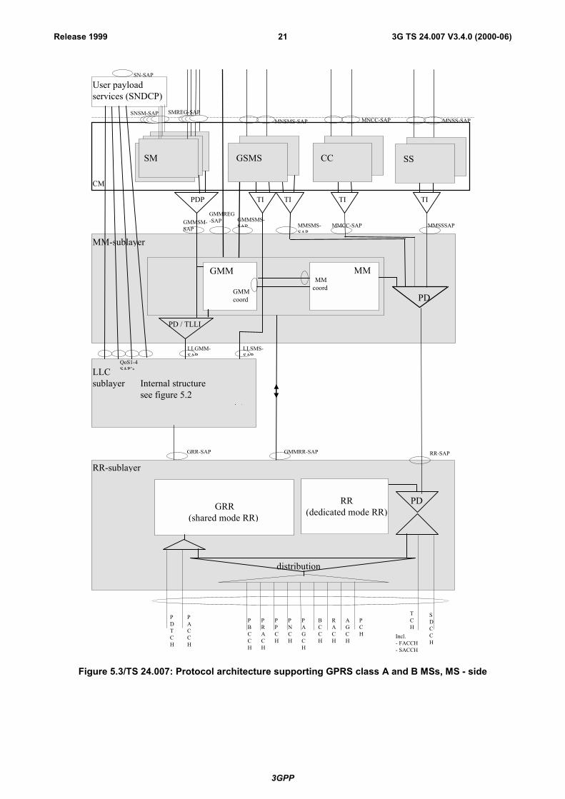
3GPP
3G TS 24.007 V3.4.0 (2000-06)21Release 1999
GMMSM-SAP
LLCsublayer
MM-sublayer
QoS1-4SAP�s
User payloadservices (SNDCP)
SN-SAP
GMM
GMM coord
MNSMS-SAP
GMMREG-SAP
LLGMM-SAP
MMSMS-SAP
MMCC-SAP MMSSSAP
LLSMS-SAP
MNSS-SAPMNCC-SAP
GMMSMS-SAP
TITIPDP TI
CM
CC SSGSMS
TI
PD / TLLI
RR-SAPGRR-SAP
RR-sublayer
GMMRR-SAP
GRR(shared mode RR)
PDTCH
PACCH
PRACH
PPCH
PAGCH
PBCCH
RACH
PCH
AGCH
BCCH
PNCH
TCH
SDCCH
PD
distribution
RR(dedicated mode RR)
MM MM coord
PD
SNSM-SAP SMREG-SAP
SM
Internal structuresee figure 5.2
Incl.- FACCH- SACCH
Figure 5.3/TS 24.007: Protocol architecture supporting GPRS class A and B MSs, MS - side
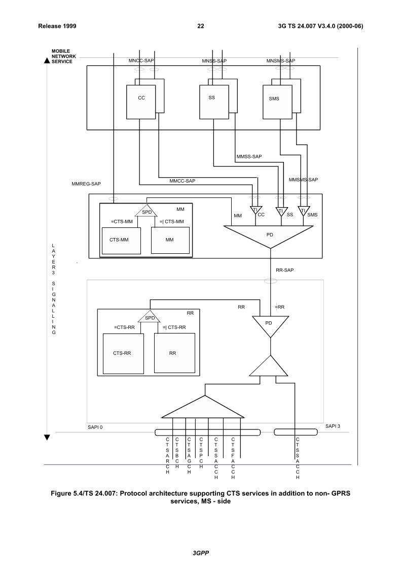
3GPP
3G TS 24.007 V3.4.0 (2000-06)22Release 1999
CTSARCH
CTSAGCH
CTSSACCH
CTSFACCH
SAPI 0 SAPI 3
RR
MM
PD
MM CC SS SMS
MMREG-SAP MMCC-SAP
MMSS-SAP
MMSMS-SAP
CC SS SMS
MOBILENETWORKSERVICE MNCC-SAP MNSS-SAP MNSMS-SAP
CTSBCH
CTSPCH
CTSSACCH
RR-SAP
RR
LAYER3
SIGNALLING
=RR
TI TI TI
PD
SPD
=CTS-RR =| CTS-RR
CTS-RR RR
SPD
=CTS-MM =| CTS-MM
CTS-MM MM
Figure 5.4/TS 24.007: Protocol architecture supporting CTS services in addition to non- GPRSservices, MS - side

3GPP
3G TS 24.007 V3.4.0 (2000-06)23Release 1999
PDP
MM-sublayer
QoS1-SAPQoS2-SAPQoS3-SAPQoS4-SAP
GSMS
MNSMS-SAP
PMMSMS-SAPGMMSM-SAP
SESSION MANAGEMENT
TI
GMMREG-SAP
CM
PD
GMM
SNSM-SAP SMREG-SAP
SN-SAP
services (SNDCP)User payload
LLC-sublayer
Figure 5.5: Protocol architecture of Non Access Stratum supporting PS mode of operation MSs,MS - side
NOTE: SMS un-related parts of this figure e.g. SNDCP should be modified for UMTS

3GPP
3G TS 24.007 V3.4.0 (2000-06)24Release 1999
GMMSM-SAP
MM-sublayer
QoS1-4SAP�s
User payloadservices (SNDCP)
SN-SAP
GMM
GMM coord
MNSMS-SAP
GMMREG-SAP
MMSMS-SAP
MMCC-SAP MMSSSAP
PMMSMS-SAP
MNSS-SAPMNCC-SAP
GMMSMS-SAP
TITIPDP TI
CM
CC SSGSMS
TI
PD
MM MM coord
PD
SNSM-SAP SMREG-SAP
SM
Figure 5.6/24.007: Protocol architecture of Non Access Stratum supporting CS/PS mode of operationMSs, MS � side
NOTE: SMS un-related parts of this figure, e.g. SNDCP should be modified for UMTS
As shown in figure 5.1 a hierarchy of 3 sublayers is defined:
- the RR sublayer provides services to the MM sublayer and utilizes the services of signalling layer 2;
- the MM sublayer provides common services to the entities of the Connection Management (CM) sublayer;
- the CM sublayer includes, among others, the CC, SS, and SMS entities, which are independent entities.
Figure 5.2 defines four sublayers for GPRS services supporting Class C MSs:
- the RR sublayer provides services to the MM and LLC sublayers;
- the LLC sublayer provides services to the MM sublayer, the SNDCP and GSMS entities and uses services of theRR sublayer;
- the MM sublayer provides services to the SM entities of the CM. The MM sublayer includes one GMM;
- the CM sublayer includes the SM and GSMS entities. The SM entity provides services to the SNDCP entity anduses services of the MM sublayer. The GSMS entity is identical to the SMS entity for non-GPRS services exceptit uses the services from the LLC sublayer.
Figure 5.3 defines four sublayers for non-GPRS and GPRS-services supporting Class A and Class B MSs:
- the RR sublayer provides services to the MM and LLC sublayers;
- the LLC sublayer provides services to the MM sublayer, the SNDCP and GSMS entities and uses services of theRR sublayer;
- the MM sublayer provides services to the SNDCP entity and to the entities of the Connection Management (CM)sublayer. In addition to the MM entity for non-GPRS services, the MM sublayer further includes one GMM
3GPP
3G TS 24.007 V3.4.0 (2000-06)25Release 1999
entity;
- the CM sublayer includes, among others, the CC, SS, GSMS and SM entities, which are independent entities.
- The SM entity provides services to the SNDCP entity and uses services of the MM sublayer.The GSMS entity is an extension of the SMS entity for non-GPRS services. For message transfer it uses theservices both from the LLC sublayer and the MM entity of the MM sublayer. Furthermore it retrieves from theMM entity information about which transport service to use.
Figure 5.4 defines three sub-layers for CTS services:
- the RR sublayer provides services (including CTS services) to the MM sublayer and uses the services ofsignalling layer 2;
- the MM sublayer provides common services to the entities of the Connection Management (CM) sublayer; itprovides also specific CTS services to the entities above CM;
- the CM sublayer includes, among others, the CC, SS, and SMS entities, which are independent entities.
Figure 5.5 defines two sublayers for UMTS PS domain services supporting PS mode of operation:
- the MM sublayer provides services to the SM entities and GSMS entities of the CM. The MM sublayer includesone GMM entity;
- the CM sublayer includes the SM and GSMS entities. The SM entity provides services to the PDCP entity anduses services of the MM sublayer. The GSMS entity is identical to the SMS entity for GPRS services in GSMexcept it uses the services from the GMM sublayer.
Figure 5.6 defines two sublayers for UMTS CS domain services and UMTS PS domain services supporting CS/PSmode of operation MSs:
- the MM sublayer provides services to the entities of the Connection Management (CM) sublayer. In addition tothe MM entity for CS domain services, the MM sublayer further includes one GMM entity;
- the CM sublayer includes, among others, the CC, SS, GSMS and SM entities, which are independent entities;
The SM entity provides services to the PDCP entity and uses services of the MM sublayer.The GSMS entity is an extension of the SMS entity for CS domain services. For message transfer it uses theservices both from the GMM entity of the MM sublayer and the MM entity of the MM sublayer. Furthermore itretrieves from the MM entity information about which transport service to use.
6 Services provided by signalling layer 3 at the MSside
The different classes of services provided by signalling layer 3 at the MS side are accessible at the following serviceaccess points:
- registration services at the MMREG-SAP or GMMREG-SAP;
- Call Control services for normal and emergency calls including call related Supplementary Services Supportservices at the MNCC-SAP;
- Short Message Services Support services at the MNSMS-SAP;
- Call independent Supplementary Services Support services at the MNSS-SAP;
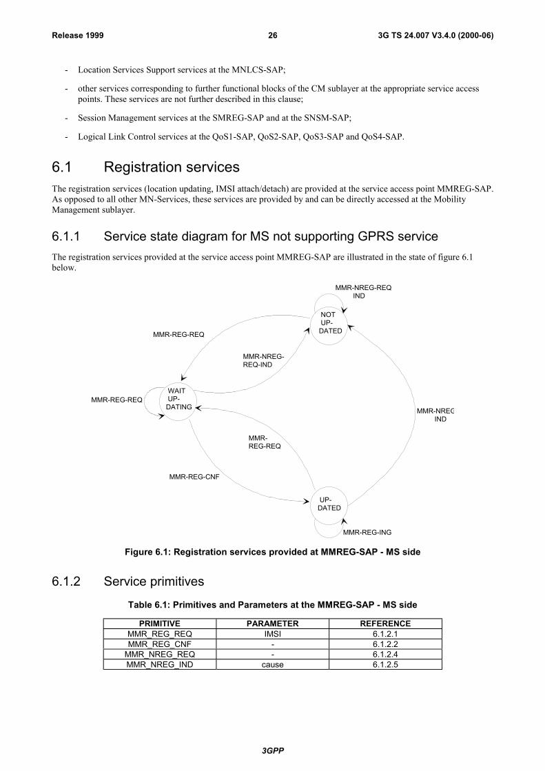
3GPP
3G TS 24.007 V3.4.0 (2000-06)26Release 1999
- Location Services Support services at the MNLCS-SAP;
- other services corresponding to further functional blocks of the CM sublayer at the appropriate service accesspoints. These services are not further described in this clause;
- Session Management services at the SMREG-SAP and at the SNSM-SAP;
- Logical Link Control services at the QoS1-SAP, QoS2-SAP, QoS3-SAP and QoS4-SAP.
6.1 Registration servicesThe registration services (location updating, IMSI attach/detach) are provided at the service access point MMREG-SAP.As opposed to all other MN-Services, these services are provided by and can be directly accessed at the MobilityManagement sublayer.
6.1.1 Service state diagram for MS not supporting GPRS serviceThe registration services provided at the service access point MMREG-SAP are illustrated in the state of figure 6.1below.
MMR-NREG-REQ IND
MMR-NREG IND
MMR-REG-ING
UP-DATED
NOT UP-DATED
WAIT UP-DATING
MMR-REG-CNF
MMR-REG-REQ
MMR-REG-REQ
MMR-REG-REQ
MMR-NREG-REQ-IND
Figure 6.1: Registration services provided at MMREG-SAP - MS side
6.1.2 Service primitives
Table 6.1: Primitives and Parameters at the MMREG-SAP - MS side
PRIMITIVE PARAMETER REFERENCEMMR_REG_REQ IMSI 6.1.2.1MMR_REG_CNF - 6.1.2.2
MMR_NREG_REQ - 6.1.2.4MMR_NREG_IND cause 6.1.2.5
3GPP
3G TS 24.007 V3.4.0 (2000-06)27Release 1999
6.1.2.1 MMR_REG_REQ
Registration request, triggered by activation of the IMSI, e.g., by activation of the MS with inserted SIM, insertion ofthe SIM into the activated MS, pressing of a reset button.
6.1.2.2 MMR_REG_CNF
Registration confirmation. Indicates to the user that the MS is ready to start a transaction.
6.1.2.3 [reserved]
6.1.2.4 MMR_NREG_REQ
Request to cancel the registration, stimulated either by removing the SIM or automatically in the power off phase.
6.1.2.5 MMR_NREG_IND
Indication that registration has been cancelled or that registration was not possible. Only emergency services areavailable to the user.
6.1.3 Registration Services for CTS-ServicesThe registration services (attach/detach, enrolment/de-enrolment) are provided for CTS services at the service accesspoint MMREG-SAP.
Table 6.1.3: Primitives and Parameters at the MMREG-SAP - MS side for CTS
PRIMITIVE PARAMETER REFERENCEMMR_CTS_ATTACH_REQ IMSI 6.1.3.1MMR_CTS_ATTACH_CNF - 6.1.3.2MMR_CTS_ATTACH_REJ IFPSI, cause 6.1.3.3MMR_CTS_DETACH_IND - 6.1.3.4MMR_CTS_ENROLL_REQ IMSI 6.1.3.5MMR_CTS_ENROLL_CNF - 6.1.3.6MMR_CTS_ENROLL_REJ IFPSI, cause 6.1.3.7
MMR_CTS_DE_ENROLL_IND
- 6.1.3.8
6.1.3.1 MMR_CTS _ATTACH_REQ
MS initiates the CTS attach. CTS-MM is requested to send a CTS ATTACH REQUEST message to the fixed part.
6.1.3.2 MMR_CTS _ATTACH_CNF
The CTS attach was successful. The fixed part confirmed the attach, i.e. the CTS ATTACH ACCEPT message wasreceived by the MS.
6.1.3.3 MMR_CTS _ATTACH_REJ
The CTS attach has failed. The fixed part rejected the attach attempt, i.e. the CTS ATTACH REJECT message wasreceived by the MS.
6.1.3.4 MMR_CTS _DETACH_IND
MS initiates CTS detach. CTS-MM is requested to send a CTS DETACH INDICATION message. The detachprocedure is initiated.

3GPP
3G TS 24.007 V3.4.0 (2000-06)28Release 1999
6.1.3.5 MMR_CTS _ENROLL_REQ
MS initiates the CTS enrolment. CTS-MM is requested to send a CTS ENROLMENT REQUEST message to the fixedpart.
6.1.3.6 MMR_CTS _ENROLL_CNF
The CTS enrolment was successful. The fixed part confirmed the enrolment, i.e. the CTS ENROLMENT ACCEPTmessage was received by the MS.
6.1.3.7 MMR_CTS _ENROLL_REJ
The CTS enrolment has failed. The fixed part rejected the enrolment attempt, i.e. the CTS ENROLMENT REJECTmessage was received by the MS.
6.1.3.8 MMR_CTS _DE_ENROLL_IND
FP initiates CTS de-enrolment. CTS-MM is requested to send a CTS DE-ENROLMENT INDICATION message. Thede-enrolment procedure is initiated.
6.2 Call Control servicesThe Call Control services are provided by multiple CC entities at the service access point MNCC-SAP.
The Call Control service class consists of the following services:
- Mobile originated and Mobile terminated call establishment for normal calls;
- Mobile originated call establishment for emergency calls;
- call maintaining;
- call termination;
- call related Supplementary Services Support.
6.2.1 Service state diagramThe Call Control services provided at the service access point MNCC-SAP are illustrated in the state diagram offigure 6.2.

3GPP
3G T
S 24
.007
V3.
4.0
(200
0-06
)29
Rel
ease
199
9
REL
EASE
REQ
UES
T
DIS
ON
NEC
TIN
DIC
ATIO
N
STA
TES
3,4,
7,8,
9,10
DIS
CO
NN
ECT
REQ
UES
T
CAL
L IN
IT
NO
CAL
LPR
OC
EED
ING
REL
EASE
R
EQU
EST
CAL
LD
ELI
VE
RE
D
ACTI
VE
CAL
LR
ECEI
VED
CO
NN
ECT
REQ
UES
T
MT
CAL
LC
ON
FIR
MED
CAL
L PR
ESEN
T
NU
LL0
1 3 419
10
19 12
6 9
7
8
11
MN
CC
-SET
UP-
IND
MN
CC
-REJ
-REQ
MN
CC
-REL
-R
EQ
MN
CC
- D
ISC
-IN
D
MN
CC
-R
EL-
IND
MN
CC
-REJ
-IND
MN
CC
-SET
UP-
REQ
MN
CC
-DIS
C-
REQ
MN
CC
-D
ISC
-IN
DM
NC
C-C
ALC
ON
F-R
EQ
MN
CC
-SE
TUP-
RSP
MN
CC
-AL
ERT-
REQ
MN
CC
-SE
TUP-
RSP
MN
CC
-SET
UP-
CO
MPL
-IND
(ER
R)
MN
CC
-D
ISC
-IN
D
MN
CC
-D
ISC
- R
EQ
MN
CC
-SET
UP-
CO
MP-
IND
MN
CC
-SET
UP-
CN
F
MN
CC
-SE
TUP-
CN
F
MN
CC
-AL
ERT-
IND
MN
CC
-REL
-R
EQ
MN
CC
-PR
OG
RES
S-IN
D
MN
CC
-CAL
LPR
OC
-IND
MN
CC
- R
EL-
CN
F
MN
CC
-FA
CIL
ITY-
IND
ANY
STAT
EEX
CEP
T 0
ANY
STAT
EM
NC
C-
REL
-IN
D
0AN
Y ST
ATE
EXC
EPT
0,19
MN
CC
-FA
CIL
ITY
REQ
Figu
re 6
.2: S
ervi
ce g
raph
of C
all C
ontr
ol e
ntity
- M
S si
de (p
age
1 of
2)
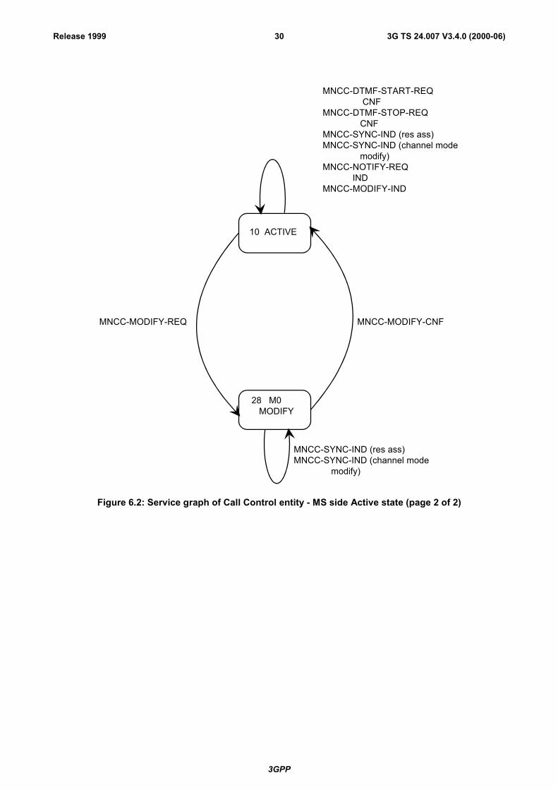
3GPP
3G TS 24.007 V3.4.0 (2000-06)30Release 1999
10 ACTIVE
28 M0 MODIFY
MNCC-MODIFY-CNFMNCC-MODIFY-REQ
MNCC-DTMF-START-REQ CNFMNCC-DTMF-STOP-REQ CNFMNCC-SYNC-IND (res ass)MNCC-SYNC-IND (channel mode modify)MNCC-NOTIFY-REQ INDMNCC-MODIFY-IND
MNCC-SYNC-IND (res ass)MNCC-SYNC-IND (channel mode modify)
Figure 6.2: Service graph of Call Control entity - MS side Active state (page 2 of 2)
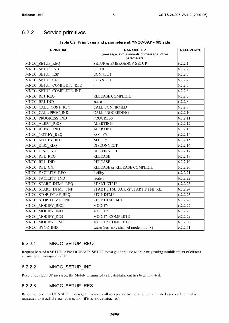
3GPP
3G TS 24.007 V3.4.0 (2000-06)31Release 1999
6.2.2 Service primitives
Table 6.2: Primitives and parameters at MNCC-SAP - MS side
PRIMITIVE PARAMETER(message, info elements of message, other
parameters)
REFERENCE
MNCC_SETUP_REQ SETUP or EMERGENCY SETUP 6.2.2.1MNCC_SETUP_IND SETUP 6.2.2.2MNCC_SETUP_RSP CONNECT 6.2.2.3MNCC_SETUP_CNF CONNECT 6.2.2.4MNCC_SETUP_COMPLETE_REQ - 6.2.2.5MNCC_SETUP_COMPLETE_IND - 6.2.2.6MNCC_REJ_REQ RELEASE COMPLETE 6.2.2.7MNCC_REJ_IND cause 6.2.2.8MNCC_CALL_CONF_REQ CALL CONFIRMED 6.2.2.9MNCC_CALL PROC_IND CALL PROCEEDING 6.2.2.10MNCC_PROGRESS_IND PROGRESS 6.2.2.11MNCC_ALERT_REQ ALERTING 6.2.2.12MNCC_ALERT_IND ALERTING 6.2.2.13MNCC_NOTIFY_REQ NOTIFY 6.2.2.14MNCC_NOTIFY_IND NOTIFY 6.2.2.15MNCC_DISC_REQ DISCONNECT 6.2.2.16MNCC_DISC_IND DISCONNECT 6.2.2.17MNCC_REL_REQ RELEASE 6.2.2.18MNCC_REL_IND RELEASE 6.2.2.19MNCC_REL_CNF RELEASE or RELEASE COMPLETE 6.2.2.20MNCC_FACILITY_REQ facility 6.2.2.21MNCC_FACILITY_IND facility 6.2.2.22MNCC_START_DTMF_REQ START DTMF 6.2.2.23MNCC_START_DTMF_CNF START DTMF ACK or START DTMF REJ 6.2.2.24MNCC_STOP_DTMF_REQ STOP DTMF 6.2.2.25MNCC_STOP_DTMF_CNF STOP DTMF ACK 6.2.2.26MNCC_MODIFY_REQ MODIFY 6.2.2.27MNCC_MODIFY_IND MODIFY 6.2.2.28MNCC_MODIFY_RES MODIFY COMPLETE 6.2.2.29MNCC_MODIFY_CNF MODIFY COMPLETE 6.2.2.30MNCC_SYNC_IND cause (res. ass., channel mode modify) 6.2.2.31
6.2.2.1 MNCC_SETUP_REQ
Request to send a SETUP or EMERGENCY SETUP message to initiate Mobile originating establishment of either anormal or an emergency call.
6.2.2.2 MNCC_SETUP_IND
Receipt of a SETUP message, the Mobile terminated call establishment has been initiated.
6.2.2.3 MNCC_SETUP_RES
Response to send a CONNECT message to indicate call acceptance by the Mobile terminated user; call control isrequested to attach the user connection (if it is not yet attached).

3GPP
3G TS 24.007 V3.4.0 (2000-06)32Release 1999
6.2.2.4 MNCC_SETUP_CNF
Receipt of a CONNECT message, the Mobile originated call has been accepted by the remote called user.
6.2.2.5 MNCC_SETUP_COMPL_REQ
Request to send a CONNECT ACKNOWLEDGE message, the mobile originating call has been accepted.
6.2.2.6 MNCC_SETUP_COMPL_IND
Receipt of a CONNECT ACKNOWLEDGE message, the Mobile terminated call establishment has been completed; fora data call, the user is informed that the user connection is attached.
6.2.2.7 MNCC_REJ_REQ
Request to reject a Mobile terminated call if the call is refused or if the call cannot be accepted, e.g., because of missingcompatibility.
6.2.2.8 MNCC_REJ_IND
Indication that the Mobile originated call has been rejected, e.g. if the MM connection cannot be provided or if the callestablishment initiation has been rejected by the network.
6.2.2.9 MNCC_CALL_CONF_REQ
Request to confirm a Mobile terminated call by sending a CALL CONFIRMED message. A bearer capability differentfrom that given in MNCC_SETUP_IND may be offered to the remote calling user.
6.2.2.10 MNCC_CALL_PROC_IND
Indication to the Mobile originating user that call establishment has been initiated in the Network and no more callestablishment information will be accepted by the Network.
6.2.2.11 MNCC_PROGRESS_IND
Indication to the Mobile user that a PROGRESS message or a message containing a progress IE has been received, e.g.,because the call is progressing in the PLMN/ISDN environment, or because the call has left the PLMN/ISDNenvironment, or because in-band tones/announcement are available.
6.2.2.12 MNCC_ALERT_REQ
Request to send an ALERTING message from the called Mobile user to the remote calling user to indicate that useralerting has been initiated.
6.2.2.13 MNCC_ALERT_IND
Indication of the receipt of an ALERTING message, alerting to the remote called user has been initiated.
6.2.2.14 MNCC_NOTIFY_REQ
Request to send information pertaining to a call, such as user suspended, to the Network by the Mobile user.
6.2.2.15 MNCC_NOTIFY_IND
Indication to the Mobile user that information pertaining to a call, such as remote user suspended, has been receivedfrom the Network.

3GPP
3G TS 24.007 V3.4.0 (2000-06)33Release 1999
6.2.2.16 MNCC_DISC_REQ
Request to send a DISCONNECT message to the Network in order to clear the end-to-end connection.
6.2.2.17 MNCC_DISC_IND
Indication of reception of a DISCONNECT message, by which the Network indicates that the end-to-end connection iscleared.
6.2.2.18 MNCC_REL_REQ
Request of the Mobile user to send a RELEASE message to inform the Network that the user intends to release the callreference and the corresponding MM connection so that the Network can release its MM connection and thecorrespondent call reference.
6.2.2.19 MNCC_REL_IND
Indication to the Mobile originating or terminated user that a RELEASE message has been received and the Networkintends to release its MM connection. The Mobile user is requested to release the call reference and the correspondingMM connection.
6.2.2.20 MNCC_REL_CNF
Confirmation of the Mobile user's request to release the MM connection and call reference in the Network. The Mobileuser may release the call reference and the corresponding MM connection.
6.2.2.21 MNCC_FACILITY_REQ
Request to transport a facility IE for a call related supplementary service invocation.
6.2.2.22 MNCC_FACILITY_IND
Indication that a facility IE for a call related supplementary service invocation has been received.
6.2.2.23 MNCC_START_DTMF_REQ
Request to send a START DTMF message in order to start a DTMF control operation.
6.2.2.24 MNCC_START_DTMF_CNF
Confirmation of the receipt of a START DTMF ACKNOWLEDGE or START DTMF REJECT message that the startof a DTMF control operation has been acknowledged or rejected.
6.2.2.25 MNCC_STOP_DTMF_REQ
Request to send a STOP DTMF message in order to stop a DTMF control operation.
6.2.2.26 MNCC_STOP_DTMF_CNF
Confirmation of the receipt of STOP DTMF ACKNOWLEDGE message, the DTMF control operation has beenstopped.
6.2.2.27 MNCC_MODIFY_REQ
Request to start Mobile originating in-call modification by sending a MODIFY message.
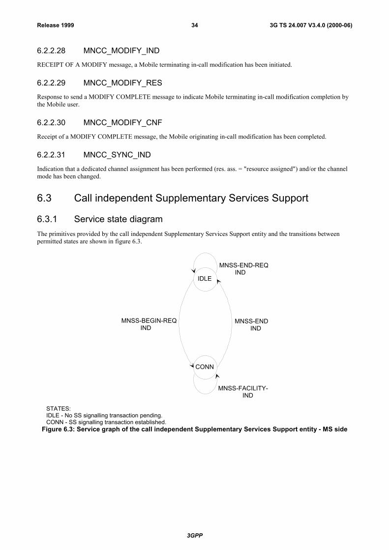
3GPP
3G TS 24.007 V3.4.0 (2000-06)34Release 1999
6.2.2.28 MNCC_MODIFY_IND
RECEIPT OF A MODIFY message, a Mobile terminating in-call modification has been initiated.
6.2.2.29 MNCC_MODIFY_RES
Response to send a MODIFY COMPLETE message to indicate Mobile terminating in-call modification completion bythe Mobile user.
6.2.2.30 MNCC_MODIFY_CNF
Receipt of a MODIFY COMPLETE message, the Mobile originating in-call modification has been completed.
6.2.2.31 MNCC_SYNC_IND
Indication that a dedicated channel assignment has been performed (res. ass. = "resource assigned") and/or the channelmode has been changed.
6.3 Call independent Supplementary Services Support
6.3.1 Service state diagramThe primitives provided by the call independent Supplementary Services Support entity and the transitions betweenpermitted states are shown in figure 6.3.
IDLE
CONN
MNSS-END IND
MNSS-FACILITY- IND
MNSS-END-REQ IND
MNSS-BEGIN-REQ IND
STATES:IDLE - No SS signalling transaction pending.CONN - SS signalling transaction established.
Figure 6.3: Service graph of the call independent Supplementary Services Support entity - MS side
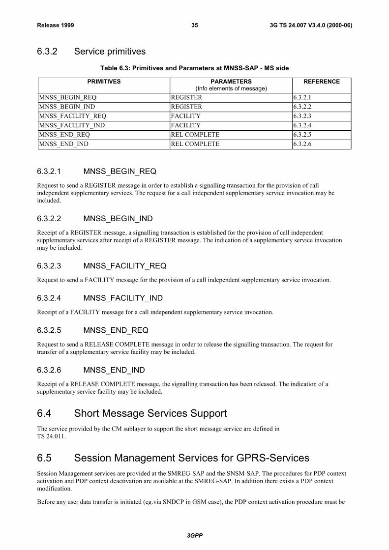
3GPP
3G TS 24.007 V3.4.0 (2000-06)35Release 1999
6.3.2 Service primitives
Table 6.3: Primitives and Parameters at MNSS-SAP - MS side
PRIMITIVES PARAMETERS(Info elements of message)
REFERENCE
MNSS_BEGIN_REQ REGISTER 6.3.2.1MNSS_BEGIN_IND REGISTER 6.3.2.2MNSS_FACILITY_REQ FACILITY 6.3.2.3MNSS_FACILITY_IND FACILITY 6.3.2.4MNSS_END_REQ REL COMPLETE 6.3.2.5MNSS_END_IND REL COMPLETE 6.3.2.6
6.3.2.1 MNSS_BEGIN_REQ
Request to send a REGISTER message in order to establish a signalling transaction for the provision of callindependent supplementary services. The request for a call independent supplementary service invocation may beincluded.
6.3.2.2 MNSS_BEGIN_IND
Receipt of a REGISTER message, a signalling transaction is established for the provision of call independentsupplementary services after receipt of a REGISTER message. The indication of a supplementary service invocationmay be included.
6.3.2.3 MNSS_FACILITY_REQ
Request to send a FACILITY message for the provision of a call independent supplementary service invocation.
6.3.2.4 MNSS_FACILITY_IND
Receipt of a FACILITY message for a call independent supplementary service invocation.
6.3.2.5 MNSS_END_REQ
Request to send a RELEASE COMPLETE message in order to release the signalling transaction. The request fortransfer of a supplementary service facility may be included.
6.3.2.6 MNSS_END_IND
Receipt of a RELEASE COMPLETE message, the signalling transaction has been released. The indication of asupplementary service facility may be included.
6.4 Short Message Services SupportThe service provided by the CM sublayer to support the short message service are defined inTS 24.011.
6.5 Session Management Services for GPRS-ServicesSession Management services are provided at the SMREG-SAP and the SNSM-SAP. The procedures for PDP contextactivation and PDP context deactivation are available at the SMREG-SAP. In addition there exists a PDP contextmodification.
Before any user data transfer is initiated (eg.via SNDCP in GSM case), the PDP context activation procedure must be

3GPP
3G TS 24.007 V3.4.0 (2000-06)36Release 1999
performed.
6.5.1 Session Management Services for SMREG-SAP
Table 6.5: Primitives and Parameters at SMREG-SAP - MS side
PRIMITIVE PARAMETER(message, info elements of message, other parameters)
REFERENCE
SMREG-PDP-ACTIVATE-REQ PDP address, QoS, NSAPI, APN, Protocolconfiguration options
6.5.1.1
SMREG-PDP-ACTIVATE-CNF PDP address, QoS, NSAPI, Protocol configurationoptions
6.5.1.2
SMREG-PDP-ACTIVATE-REJ Cause, NSAPI, Protocol configuration options 6.5.1.3
SMREG-PDP-ACTIVATE-IND PDP address, APN 6.5.1.4
SMREG-PDP-ACTIVATE-REJ-RSP Cause, PDP address, APN 6.5.1.14
SMREG-PDP-DEACTIVATE-REQ NSAPI(s) tear down indicator, cause 6.5.1.5
SMREG-PDP-DEACTIVATE-CNF NSAPI(s) 6.5.1.6
SMREG-PDP-DEACTIVATE-IND NSAPI(s) (s), tear down indicator, cause 6.5.1.7
SMREG-PDP-MODIFY-IND QoS, NSAPI 6.5.1.8
SMREG-PDP-MODIFY-REQ QoS, NSAPI, TFT 6.5.1.18
SMREG-PDP-MODIFY-CNF QoS, NSAPI 6.5.1.19
SMREG-PDP-MODIFY-REJ Cause, NSAPI 6.5.1.20
SMREG-PDP-ACTIVATE-SEC-REQ QoS, NSAPI, TFT, Primary NSAPI 6.5.1.15
SMREG-PDP-ACTIVATE-SEC-CNF QoS, NSAPI 6.5.1.16
SMREG-PDP-ACTIVATE-SEC-REJ Cause, NSAPI 6.5.1.17
6.5.1.1 SMREG-PDP-ACTIVATE-REQ
The MS initiates a primary PDP context activation. SM is requested to send the ACTIVATE PDP CONTEXTREQUEST message to the network. The PDP context is pending activation.
6.5.1.2 SMREG-PDP-ACTIVATE-CNF
The MS initiated primary PDP context activation succeeded. The network confirmed the PDP context activation, i.e.the ACTIVATE PDP CONTEXT ACCEPT message was received from the network. In GSM, this implies that SM hasordered SNDCP to establish the needed LLC link. In the UMTS case, this implies that the RLC link towards the RNChas been established and that the SM has been informed about this from the RABM service entity in the MS. (RABM-RAB Management service entity is FFS and could lead to update of the protocol architecture in figure 5.2 and 5.3) ThePDP context is active.
6.5.1.3 SMREG-PDP-ACTIVATE-REJ
The PDP primary context activation failed, the PDP context is not activated. One reason for failure is that the networkrejected the activation attempt, which means the ACTIVATE PDP CONTEXT REJECT message was received.Another reason is e.g. that it was not possible to establish the needed LLC link in the GSM case.

3GPP
3G TS 24.007 V3.4.0 (2000-06)37Release 1999
6.5.1.4 SMREG-PDP-ACTIVATE-IND
The network asked for a PDP context activation. The REQUEST PDP CONTEXT ACTIVATION message wasreceived from the network. The MS reacts either by initiating a new primary PDP context activation or by rejecting thenetwork�s request.
6.5.1.5 SMREG-PDP-DEACTIVATE-REQ
The MS initiates a PDP context deactivation: SM is requested to send a DEACTIVATE PDP CONTEXT REQUESTmessage to the network. The PDP context is pending deactivation. Presence of the teardown indicator will lead todeactivation of all PDP contexts coupled to the identified PDP address. NSAPI(s) to be deallocated from the SNDCPentity via the SNSM-SAP for the GSM case, are included in the primitive.
6.5.1.6 SMREG-PDP-DEACTIVATE-CNF
The MS initiated PDP context deactivation has been done. The network confirmed the PDP context deactivation, i.e.the DEACTIVATE PDP CONTEXT ACCEPT message was received from the network. For GSM SM has orderedSNDCP to locally release not further needed LLC links. In the UMTS case, the release of the RLC link towards theRNC takes place as a result of a RAB release trigger from the network side. SM has been informed about this from theRABM service entity in the MS. (RABM- RAB Management service entity is FFS and could lead to update of theprotocol architecture in figure 5.2 and 5.3) The PDP context has been deactivated.
6.5.1.7 SMREG-PDP-DEACTIVATE-IND
A network initiated PDP context deactivation has been performed. The DEACTIVATE PDP CONTEXT REQUESTmessage has been received from the network. The MS has acknowledged with the DEACIVATE PDP CONTEXTACCEPT message. The PDP context has been deactivated, Not further needed LLC links were locally released.Presence of the teardown indicator will lead to deactivation of all PDP contexts coupled to the identified PDP address.NSAPI is included in the primitive to allow identification of the PDP context(s) needing deactivation.
6.5.1.8 SMREG-PDP-MODIFY-IND
A network initiated PDP context modification has been performed. The MODIFY PDP CONTEXT REQUESTmessage has been received from the network. The modification has been acknowledged by sending the MODIFY PDPCONTEXT ACCEPT message. One PDP context has been modified. LLC links is adjusted.
6.5.1.9 VOID
6.5.1.10 VOID
6.5.1.11 VOID
6.5.1.12 VOID
6.5.1.13 VOID
6.5.1.14 SMREG-PDP-ACTIVATE-REJ-RSP
The network requested PDP context activation failed.
6.5.1.15 SMREG-PDP-ACTIVATE-SEC-REQ
The MS initiates a secondary PDP context activation. SM is requested to send the ACTIVATE SECONDARY PDPCONTEXT REQUEST message to the network. The PDP context is pending activation.

3GPP
3G TS 24.007 V3.4.0 (2000-06)38Release 1999
6.5.1.16 SMREG-PDP-ACTIVATE-SEC-CNF
The MS initiated secondary PDP context activation succeeded. The network confirmed the PDP context activation, i.e.the ACTIVATE SECONDARY PDP CONTEXT ACCEPT message was received from the network. In GSM, thisimplies that SM has ordered SNDCP to establish the needed LLC link. In the UMTS case, this implies that the RLC linktowards the RNC has been established and that the SM has been informed about this from the RABM service entity inthe MS. (RABM- RAB Management service entity is FFS and could lead to update of the protocol architecture infigure 5.2 and 5.3) The PDP context connected to the same PDP address as the PDP context identified by the primaryNSAPI parameter in SMREG-PDP-ACTIVATE-SEC-REQ is active. (�Primary NSAPI� will point to any one of theother established PDP contexts for a given PDP address).
6.5.1.17 SMREG-PDP-ACTIVATE-SEC-REJ
The secondary PDP context activation failed, the PDP context is not activated. One reason for failure is that the networkrejected the activation attempt, which means the ACTIVATE SECONDARY PDP CONTEXT REJECT message wasreceived. Another reason is e.g. that it was not possible to establish the needed LLC link in the GSM case.
6.5.1.18 SMREG-PDP-MODIFY-REQ
An MS initiated PDP context modification is requested. The MODIFY PDP CONTEXT REQUEST message is sent tothe network and pending acceptance. Affected PDP context is identified via the NSAPI value included in the primitive.
6.5.1.19 SMREG-PDP-MODIFY-CNF
An MS initiated PDP context modification has been accepted by the network. The modification is acknowledged fromthe network via the MODIFY PDP CONTEXT ACCEPT message. The addressed PDP context has been modified. LLCor RLC link is adjusted according to the QoS returned from the network.
6.5.1.20 SMREG-PDP-MODIFY-REJ
An MS initiated PDP context modification has been rejected by the network. The rejection is signalled from thenetwork via the MODIFY PDP CONTEXT REJECT message with the cause code. The PDP context remains activewithout change of QoS.
The session management services provided at the service access point SMREG-SAP are illustrated in the state machinesof figure 6.4 below. Note, that the state machine describes only one PDP context within the SM entity.
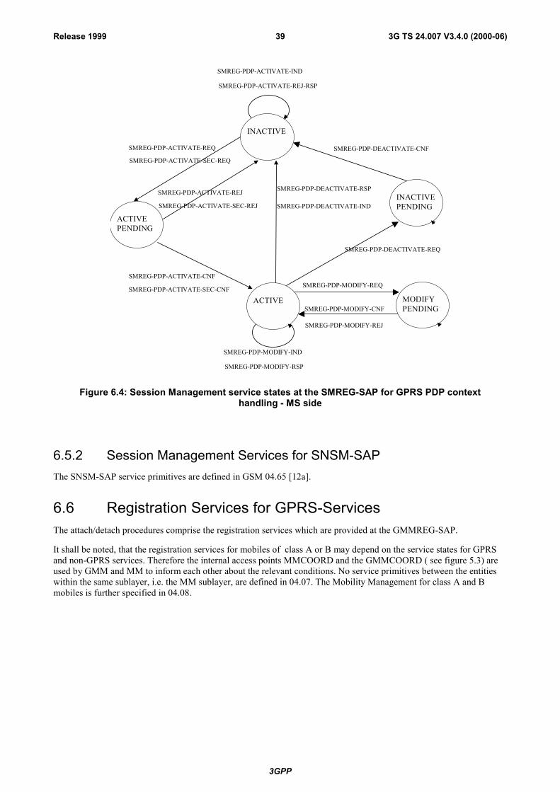
3GPP
3G TS 24.007 V3.4.0 (2000-06)39Release 1999
ACTIVE
SMREG-PDP-ACTIVATE-REQ
ACTIVEPENDING
SMREG-PDP-ACTIVATE-CNF
INACTIVE
SMREG-PDP-DEACTIVATE-RSP
SMREG-PDP-MODIFY-IND
SMREG-PDP-DEACTIVATE-IND
SMREG-PDP-MODIFY-RSP
MODIFYPENDING
SMREG-PDP-MODIFY-REQ
SMREG-PDP-MODIFY-CNF
INACTIVEPENDING
SMREG-PDP-DEACTIVATE-REQ
SMREG-PDP-DEACTIVATE-CNF
SMREG-PDP-ACTIVATE-SEC-REQ
SMREG-PDP-ACTIVATE-SEC-CNF
SMREG-PDP-ACTIVATE-IND
SMREG-PDP-ACTIVATE-REJ-RSP
SMREG-PDP-MODIFY-REJ
SMREG-PDP-ACTIVATE-REJ
SMREG-PDP-ACTIVATE-SEC-REJ
Figure 6.4: Session Management service states at the SMREG-SAP for GPRS PDP contexthandling - MS side
6.5.2 Session Management Services for SNSM-SAPThe SNSM-SAP service primitives are defined in GSM 04.65 [12a].
6.6 Registration Services for GPRS-ServicesThe attach/detach procedures comprise the registration services which are provided at the GMMREG-SAP.
It shall be noted, that the registration services for mobiles of class A or B may depend on the service states for GPRSand non-GPRS services. Therefore the internal access points MMCOORD and the GMMCOORD ( see figure 5.3) areused by GMM and MM to inform each other about the relevant conditions. No service primitives between the entitieswithin the same sublayer, i.e. the MM sublayer, are defined in 04.07. The Mobility Management for class A and Bmobiles is further specified in 04.08.
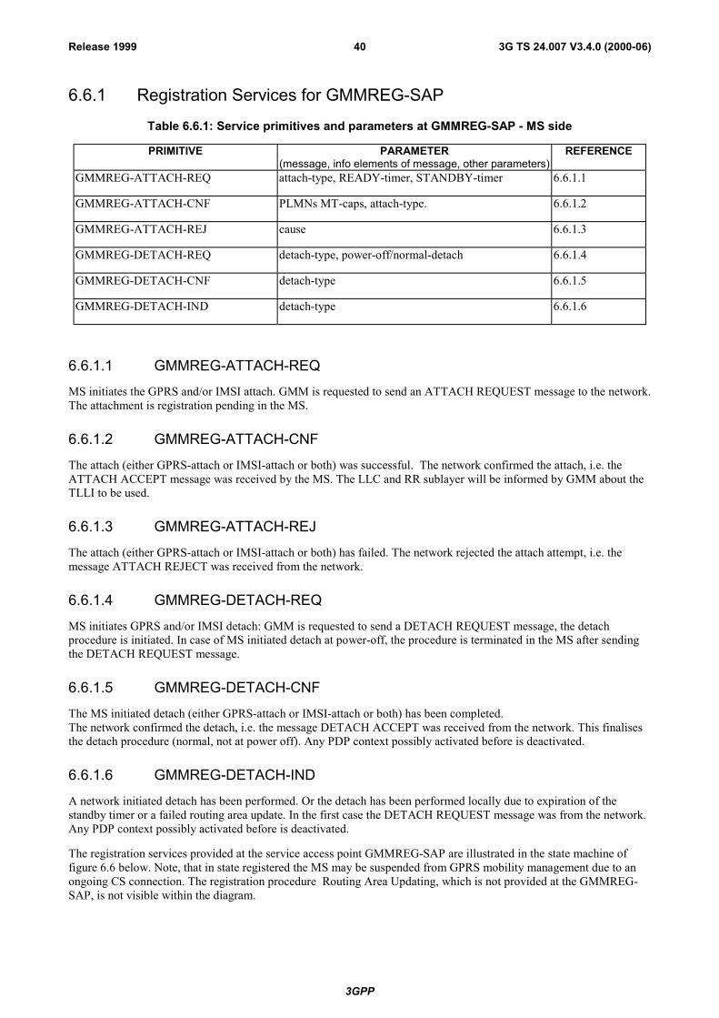
3GPP
3G TS 24.007 V3.4.0 (2000-06)40Release 1999
6.6.1 Registration Services for GMMREG-SAP
Table 6.6.1: Service primitives and parameters at GMMREG-SAP - MS side
PRIMITIVE PARAMETER(message, info elements of message, other parameters)
REFERENCE
GMMREG-ATTACH-REQ attach-type, READY-timer, STANDBY-timer 6.6.1.1
GMMREG-ATTACH-CNF PLMNs MT-caps, attach-type. 6.6.1.2
GMMREG-ATTACH-REJ cause 6.6.1.3
GMMREG-DETACH-REQ detach-type, power-off/normal-detach 6.6.1.4
GMMREG-DETACH-CNF detach-type 6.6.1.5
GMMREG-DETACH-IND detach-type 6.6.1.6
6.6.1.1 GMMREG-ATTACH-REQ
MS initiates the GPRS and/or IMSI attach. GMM is requested to send an ATTACH REQUEST message to the network.The attachment is registration pending in the MS.
6.6.1.2 GMMREG-ATTACH-CNF
The attach (either GPRS-attach or IMSI-attach or both) was successful. The network confirmed the attach, i.e. theATTACH ACCEPT message was received by the MS. The LLC and RR sublayer will be informed by GMM about theTLLI to be used.
6.6.1.3 GMMREG-ATTACH-REJ
The attach (either GPRS-attach or IMSI-attach or both) has failed. The network rejected the attach attempt, i.e. themessage ATTACH REJECT was received from the network.
6.6.1.4 GMMREG-DETACH-REQ
MS initiates GPRS and/or IMSI detach: GMM is requested to send a DETACH REQUEST message, the detachprocedure is initiated. In case of MS initiated detach at power-off, the procedure is terminated in the MS after sendingthe DETACH REQUEST message.
6.6.1.5 GMMREG-DETACH-CNF
The MS initiated detach (either GPRS-attach or IMSI-attach or both) has been completed.The network confirmed the detach, i.e. the message DETACH ACCEPT was received from the network. This finalisesthe detach procedure (normal, not at power off). Any PDP context possibly activated before is deactivated.
6.6.1.6 GMMREG-DETACH-IND
A network initiated detach has been performed. Or the detach has been performed locally due to expiration of thestandby timer or a failed routing area update. In the first case the DETACH REQUEST message was from the network.Any PDP context possibly activated before is deactivated.
The registration services provided at the service access point GMMREG-SAP are illustrated in the state machine offigure 6.6 below. Note, that in state registered the MS may be suspended from GPRS mobility management due to anongoing CS connection. The registration procedure Routing Area Updating, which is not provided at the GMMREG-SAP, is not visible within the diagram.
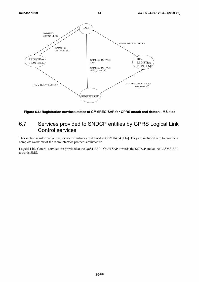
3GPP
3G TS 24.007 V3.4.0 (2000-06)41Release 1999
IDLE
REGISTRA-TION PEND.
GMMREG-ATTACH-REQ
GMMREG-ATTACH-CFN
GMMREG-ATTACH-REJ
GMMREG-DETACH-CFN
REGISTERED
GMMREG-DETACH-IND
GMMREG-DETACH-REQ (power off)
GMMREG-DETACH-REQ(not power off)
DE-REGISTRA-TION PEND.
Figure 6.6: Registration services states at GMMREG-SAP for GPRS attach and detach - MS side
6.7 Services provided to SNDCP entities by GPRS Logical LinkControl services
This section is informative, the service primitives are defined in GSM 04.64 [11a]. They are included here to provide acomplete overview of the radio interface protocol architecture.
Logical Link Control services are provided at the QoS1-SAP - QoS4 SAP towards the SNDCP and at the LLSMS-SAPtowards SMS.
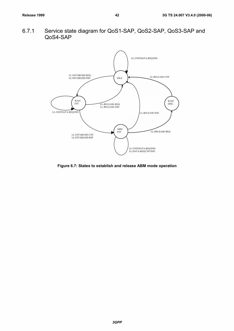
3GPP
3G TS 24.007 V3.4.0 (2000-06)42Release 1999
6.7.1 Service state diagram for QoS1-SAP, QoS2-SAP, QoS3-SAP andQoS4-SAP
LL-ESTABLISH-REQLL-ESTABLISH-IND
LL-ESTABLISH-CNFLL-ESTABLISH-RSP
LL-UNITDATA-REQ/IND
LL-UNITDATA-REQ/IND LL-RELEASE-IND
LL-UNITDATA-REQ/INDLL-DATA-REQ/CNF/IND
IDLE
WAITEST
LL-RELEASE-CNF
LL-RELEASE-REQLL-RELEASE-IND
LL-RELEASE-REQ
LL-RELEASE-REQLL-RELEASE-IND
WAITDISC.
ABMEST
Figure 6.7: States to establish and release ABM mode operation

3GPP
3G TS 24.007 V3.4.0 (2000-06)43Release 1999
6.7.2 Service primitives for QoS1-SAP, QoS2-SAP, QoS3-SAP andQoS4-SAP
Table 6.7.2: Service primitives and parameters at QoS1 to QoS4 - MS side
PRIMITIVE PARAMETER(message, info elements of message, other parameters)
REFERENCE
LL-ESTABLISH-REQ TLLI, SNDCP requested parameters (XID) 6.7.2.1
LL-ESTABLISH-CNF TLLI, SNDCP negotiated parameters (XID) 6.7.2.2
LL-ESTABLISH-IND TLLI, SNDCP requested parameters (XID), N201 6.7.2.3
LL-ESTABLISH-RSP TLLI, SNDCP negotiated parameters (XID) 6.7.2.4
LL-RELEASE-REQ TLLI 6.7.2.5
LL-RELEASE-CFN TLLI 6.7.2.6
LL-RELEASE-IND TLLI 6.7.2.7
LL-XID-REQ TLLI, SNDCP requested parameters (XID) 6.7.2.8
LL-XID-IND TLLI, SNDCP requested parameters (XID), N201 6.7.2.9
LL-XID-RSP TLLI, SNDCP negotiated parameters (XID) 6.7.2.10
LL-XID-CNF TLLI, SNDCP negotiated parameters (XID), N201 6.7.2.11
LL-DATA-REQ TLLI, N-PDU, local reference 6.7.2.12
LL-DATA-CNF TLLI, local reference 6.7.2.13
LL-DATA-IND TLLI, N-PDU 6.7.2.14
LL-UNITDATA-REQ TLLI, N-PDU, protect, cipher 6.7.2.15
LL-UNITDATA-IND TLLI, N-PDU 6.7.2.16
LL-STATUS-IND TLLI, cause 6.7.2.17
6.7.2.1 LL-ESTABLISH-REQ
A LLC SABM frame will be sent to establish the LLC ABM mode.
6.7.2.2 LL-ESTABLISH-CNF
A LLC UA frame is received, the LLC ABM mode has been established.
6.7.2.3 LL-ESTABLISH-IND
A LLC SABM frame is received.
6.7.2.4 LL-ESTABLISH-RSP
A LLC UA frame will be sent, the ABM mode is established.
6.7.2.5 LL-RELEASE-REQ
A LLC DISC frame will be sent to change to LLC ADM mode.
3GPP
3G TS 24.007 V3.4.0 (2000-06)44Release 1999
6.7.2.6 LL-RELEASE-CNF
The LLC link has been disconnected, LLC is in ADM mode.
6.7.2.7 LL-RELEASE-IND
LLC is in idle mode.
6.7.2.8 LL-XID-REQ
An LLC XID frame will be sent.
6.7.2.9 LL-XID-IND
An LLC XID frame has been received.
6.7.2.10 LL-XID-RSP
An LLC XID frame will be sent as a response to a received XID frame.
6.7.2.11 LL-XID-CNF
An LLC XID frame has been received as a response to a sent XID frame.
6.7.2.12 LL-DATA-REQ
An LLC I frame will be sent to the peer entity.
6.7.2.13 LL-DATA-CNF
Successful reception of an LLC I frame has been acknowledged by the peer entity.
6.7.2.14 LL-DATA-IND
An LLC I frame has been received from the peer entity.
6.7.2.15 LL-UNITDATA-REQ
An LLC UI frame will be sent to the peer entity.
6.7.2.16 LL-UNITDATA-IND
An LLC UI frame has been received from the peer entity.
6.7.2.17 LL-STATUS-IND
Indication used by LLC to transfer LLC failures to the SNDCP sublayer. The failure may also be caused due to errors atthe RLC/MAC layer.
6.8 Location services at the MS sideThe location services (initiation of positioning measurements at the MS are provided at the service access pointMNLCS-SAP. The service provided by the CM sublayer to support the location services is defined in GSM 04.71.

3GPP
3G TS 24.007 V3.4.0 (2000-06)45Release 1999
6.8.1 Service state diagramThe positioning services provided at the service access point MNLCS-SAP are illustrated in the state diagram offigure 6.8.
Connected
Idle
MNLCS-BEGIN-REQ IND
MNLCS-END-REQ IND
MNLCS-END-REQ IND
MNLCS-FACILITY-REQ IND
STATES:IDLE - No LCS signalling transaction pending.CONN - LCS signalling transaction established.
Figure 6.8: Service graph of the Location Services Support entity - MS side

3GPP
3G TS 24.007 V3.4.0 (2000-06)46Release 1999
6.8.2 Service primitives
Table 6.8: Primitives and Parameters at MNLCS-SAP - MS side
PRIMITIVES PARAMETERS(Info elements of message)
REFERENCE
MNLCS_BEGIN_REQ REGISTER 6.8.2.1MNLCS_BEGIN_IND REGISTER 6.8.2.2MNLCS_FACILITY_REQ FACILITY 6.8.2.3MNLCS_FACILITY_IND FACILITY 6.8.2.4MNLCS_END_REQ RELEASE COMPLETE 6.8.2.5MNLCS_END_IND RELEASE COMPLETE 6.8.2.6
6.8.2.1 MNLCS_BEGIN_REQ
Request to send a REGISTER message in order to establish a signalling transaction for the provision of locationservices. The request for transfer of a location service facility may be included.
6.8.2.2 MNLCS_BEGIN_IND
Receipt of a REGISTER message, a signalling transaction is established for the provision of location services afterreceipt of a REGISTER message. The indication of a location service facility may be included.
6.8.2.3 MNLCS_FACILITY_REQ
Request to send a FACILITY message for the provision of a location service invocation. The request for transfer of alocation service facility may be included.
6.8.2.4 MNLCS_FACILITY_IND
Receipt of a FACILITY message, a location service facility has been requested.
6.8.2.5 MNLCS_END_REQ
Request to send a RELEASE COMPLETE message in order to release the signalling transaction. The request fortransfer of a location service facility may be included.
6.8.2.6 MNLCS_END_IND
Receipt of a RELEASE COMPLETE message, the signalling transaction has been released. The indication of a locationservice facility may be included.
3GPP
3G TS 24.007 V3.4.0 (2000-06)47Release 1999
7 Services provided by signalling layer 3 on theNetwork side
In this clause, the services provided by signalling layer 3 on the network side are described which belong to the CMsub-layer functional blocks of CC, SMS, and SS. The services corresponding to further functional blocks of the CMsublayer are not further described in this clause.
7.1 Call control servicesThe Call Control services are provided by multiple CC entities at the service access point MNCC-SAP.
The Call Control service class consists of the following services:
- call establishment;
- call maintaining;
- call termination;
- call related Supplementary Services Support.
7.1.1 Service state diagramThe Call Control services provided at the service access point MNCC-SAP are illustrated in figure 7.1.

3GPP
3G T
S 24
.007
V3.
4.0
(200
0-06
)48
Rel
ease
199
9
REL
EASE
REQ
UES
T
DIS
ON
NEC
TIN
DIC
ATIO
ND
ISC
ON
NEC
TR
EQU
EST
CAL
L IN
IT
NO
CAL
LPR
OC
EED
ING
CAL
LD
ILIV
ERED
ACTI
VE
CAL
LR
ECEI
VED
CO
NN
ECT
REQ
UES
T
MT
CAL
LC
ON
FIR
MED
CAL
L PR
ESEN
T
NU
LL0
1 3
4
10
19
12
6 9
7
8
11
MN
CC
-R
EL-
IND
MN
CC
-REJ
-IND
MN
CC
-SET
UP-
REQ
MN
CC
-D
ISC
-IN
D
MN
CC
-D
ISC
- R
EQM
NC
C-
ALER
T-IN
D
MN
CC
-FA
CIL
ITY-
IND
ANY
STAT
EEX
CEP
T 0
ANY
STAT
EM
NC
C-
REL
-IN
D0
ANY
STAT
EEX
CEP
T 0,
19M
NC
C-
FAC
ILIT
YR
EQ
MN
CC
-SET
UP-
REQ
MN
CC
-REJ
-IND
STA
TES
4,6,
8,9,
10
MN
CC
-R
EL-C
NF
MN
CC
-D
ISC
- IN
D
MN
CC
-C
ALL-
CO
NF-
IND
MN
CC
-AL
ERT-
IND
MN
CC
-SE
TUP-
CN
F
MN
CC
-SE
TUP-
CN
F
MN
CC
-SET
UP-
CO
MPL
-REQ
MN
CC
-CAL
LPR
OC
-REQ CO
NN
ECT
IND
ICAT
ION
28
MN
CC
-PR
OG
RES
S-R
EQM
NC
C-
ALER
T-R
EQ MN
CC
-SE
TUP-
RSP
MN
CC
-REL
REQ
Figu
re 7
.1: (
page
1 o
f 2) S
ervi
ce g
raph
of C
all C
ontr
ol e
ntity
- N
etw
ork
side
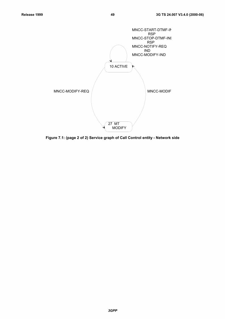
3GPP
3G TS 24.007 V3.4.0 (2000-06)49Release 1999
10 ACTIVE
27 MT MODIFY
MNCC-MODIFYMNCC-MODIFY-REQ
MNCC-START-DTMF-IN RSPMNCC-STOP-DTMF-IND RSPMNCC-NOTIFY-REQ INDMNCC-MODIFY-IND
Figure 7.1: (page 2 of 2) Service graph of Call Control entity - Network side
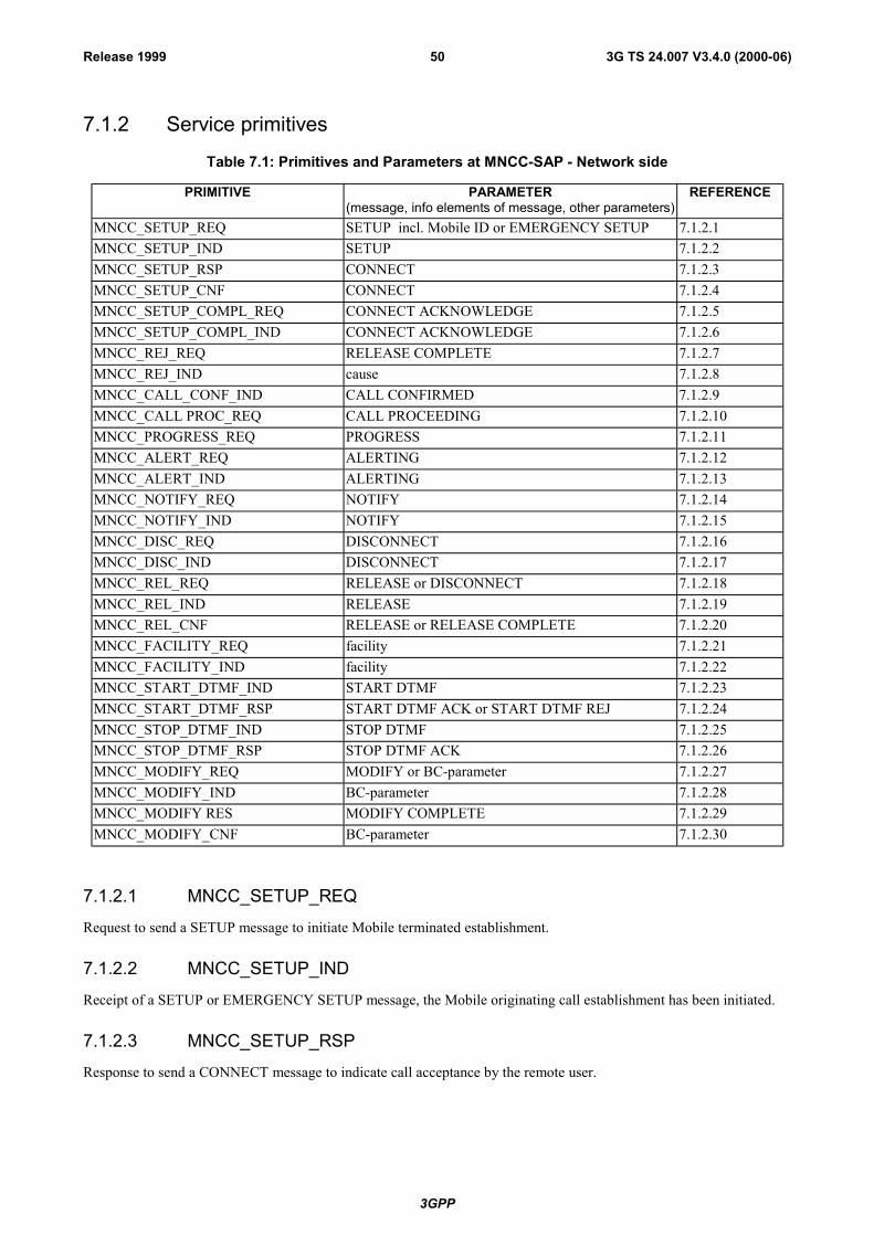
3GPP
3G TS 24.007 V3.4.0 (2000-06)50Release 1999
7.1.2 Service primitives
Table 7.1: Primitives and Parameters at MNCC-SAP - Network side
PRIMITIVE PARAMETER(message, info elements of message, other parameters)
REFERENCE
MNCC_SETUP_REQ SETUP incl. Mobile ID or EMERGENCY SETUP 7.1.2.1MNCC_SETUP_IND SETUP 7.1.2.2MNCC_SETUP_RSP CONNECT 7.1.2.3MNCC_SETUP_CNF CONNECT 7.1.2.4MNCC_SETUP_COMPL_REQ CONNECT ACKNOWLEDGE 7.1.2.5MNCC_SETUP_COMPL_IND CONNECT ACKNOWLEDGE 7.1.2.6MNCC_REJ_REQ RELEASE COMPLETE 7.1.2.7MNCC_REJ_IND cause 7.1.2.8MNCC_CALL_CONF_IND CALL CONFIRMED 7.1.2.9MNCC_CALL PROC_REQ CALL PROCEEDING 7.1.2.10MNCC_PROGRESS_REQ PROGRESS 7.1.2.11MNCC_ALERT_REQ ALERTING 7.1.2.12MNCC_ALERT_IND ALERTING 7.1.2.13MNCC_NOTIFY_REQ NOTIFY 7.1.2.14MNCC_NOTIFY_IND NOTIFY 7.1.2.15MNCC_DISC_REQ DISCONNECT 7.1.2.16MNCC_DISC_IND DISCONNECT 7.1.2.17MNCC_REL_REQ RELEASE or DISCONNECT 7.1.2.18MNCC_REL_IND RELEASE 7.1.2.19MNCC_REL_CNF RELEASE or RELEASE COMPLETE 7.1.2.20MNCC_FACILITY_REQ facility 7.1.2.21MNCC_FACILITY_IND facility 7.1.2.22MNCC_START_DTMF_IND START DTMF 7.1.2.23MNCC_START_DTMF_RSP START DTMF ACK or START DTMF REJ 7.1.2.24MNCC_STOP_DTMF_IND STOP DTMF 7.1.2.25MNCC_STOP_DTMF_RSP STOP DTMF ACK 7.1.2.26MNCC_MODIFY_REQ MODIFY or BC-parameter 7.1.2.27MNCC_MODIFY_IND BC-parameter 7.1.2.28MNCC_MODIFY RES MODIFY COMPLETE 7.1.2.29MNCC_MODIFY_CNF BC-parameter 7.1.2.30
7.1.2.1 MNCC_SETUP_REQ
Request to send a SETUP message to initiate Mobile terminated establishment.
7.1.2.2 MNCC_SETUP_IND
Receipt of a SETUP or EMERGENCY SETUP message, the Mobile originating call establishment has been initiated.
7.1.2.3 MNCC_SETUP_RSP
Response to send a CONNECT message to indicate call acceptance by the remote user.

3GPP
3G TS 24.007 V3.4.0 (2000-06)51Release 1999
7.1.2.4 MNCC_SETUP_CNF
Receipt of a CONNECT message, the Mobile terminated call has been accepted.
7.1.2.5 MNCC_SETUP_COMPL_REQ
Request to send a CONNECT ACKNOWLEDGE message, the Mobile terminated call establishment has beencompleted.
7.1.2.6 MNCC_SETUP_COMPL_IND
Indication of the receipt of a CONNECT ACKNOWLEDGE message, the Mobile originating call establishment hasbeen completed.
7.1.2.7 MNCC_REJ_REQ
Reject the Mobile originated call establishment if the call cannot be accepted.
7.1.2.8 MNCC_REJ_IND
A Mobile terminated call was rejected by the MS, e.g. because of missing compatibility.
7.1.2.9 MNCC_CALL_CONF_IND
Receipt of a CALL CONFIRMED message, the Mobile terminated call has been confirmed. A bearer capabilitydifferent from that given in MNCC_SETUP_REQ may be offered to the remote calling user.
7.1.2.10 MNCC_CALL_PROC_REQ
Request to send a CALL PROCEEDING message to indicate to the Mobile originating user that call establishment hasbeen initiated in the Network and no more call establishment information will be accepted.
7.1.2.11 MNCC_PROGRESS_REQ
Request to send a PROGRESS message or to piggy-back a progress IE in a suitable CC message in order to give theMobile user information about the call , e.g., that the call is progressing in the PLMN/ISDN environment, or that thecall has left the PLMN/ISDN environment, or that in-band tones/announcement are available.
7.1.2.12 MNCC_ALERT_REQ
Request to send an ALERTING message to indicate to the Mobile originating user that remote called user alerting hasbeen initiated.
7.1.2.13 MNCC_ALERT_IND
Receipt of an ALERTING message from the Mobile terminated user to be sent to the remote calling user to indicate thatuser alerting has been initiated.
7.1.2.14 MNCC_NOTIFY_REQ
Request to send information pertaining to a call, such as user suspended, to the Mobile originating or the Mobileterminated user.
7.1.2.15 MNCC_NOTIFY_IND
Indication from the Mobile originating or Mobile terminated user of information pertaining to a call, such as remoteuser suspended.
3GPP
3G TS 24.007 V3.4.0 (2000-06)52Release 1999
7.1.2.16 MNCC_DISC_REQ
Request to send a DISCONNECT message to the MS in order to clear the end-to-end connection.
7.1.2.17 MNCC_DISC_IND
Receipt of a DISCONNECT message, the MS indicates that the end-to-end connection is cleared.
7.1.2.18 MNCC_REL_REQ
Request to send a RELEASE message to inform the MS that the network intends to release the MM connection and thecorrespondent call reference.
7.1.2.19 MNCC_REL_IND
Receipt of a RELEASE message, the MS intends to release its MM connection and call reference. The Network isrequested to release its call reference and MM connection.
7.1.2.20 MNCC_REL_CNF
The RELEASE COMPLETE message has been received, the MM connection in the MS has been released, the Networkitself shall release its MM connection and the corresponding call reference.
7.1.2.21 MNCC_FACILITY_REQ
Request to transport a facility IE for call related supplementary service invocations.
7.1.2.22 MNCC_FACILITY_IND
Indication that a facility IE for call related supplementary service invocations has been received.
7.1.2.23 MNCC_START_DTMF_IND
Indicate the receipt of a START DTMF message in order to start a DTMF control operation.
7.1.2.24 MNCC_START_DTMF_RSP
Request to send a START DTMF ACKNOWLEDGE or START DTMF REJECT message in order to acknowledge orreject the start of a DTMF control operation.
7.1.2.25 MNCC_STOP_DTMF_IND
Indicate the receipt of a STOP DTMF message in order to stop a DTMF control operation.
7.1.2.26 MNCC_STOP_DTMF_RSP
Request to send a STOP DTMF ACKNOWLEDGE message in order to acknowledge the completion of a DTMFcontrol operation.
7.1.2.27 MNCC_MODIFY_REQ
Request to start the Mobile terminating in-call modification.
7.1.2.28 MNCC_MODIFY_IND
Receipt of a MODIFY message, the Mobile originating in-call modification has been initiated.
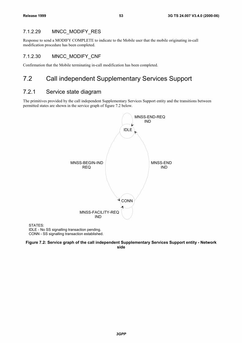
3GPP
3G TS 24.007 V3.4.0 (2000-06)53Release 1999
7.1.2.29 MNCC_MODIFY_RES
Response to send a MODIFY COMPLETE to indicate to the Mobile user that the mobile originating in-callmodification procedure has been completed.
7.1.2.30 MNCC_MODIFY_CNF
Confirmation that the Mobile terminating in-call modification has been completed.
7.2 Call independent Supplementary Services Support
7.2.1 Service state diagramThe primitives provided by the call independent Supplementary Services Support entity and the transitions betweenpermitted states are shown in the service graph of figure 7.2 below.
IDLE
CONN
MNSS-END IND
MNSS-BEGIN-IND REQ
MNSS-FACILITY-REQ IND
MNSS-END-REQ IND
STATES:IDLE - No SS signalling transaction pending.CONN - SS signalling transaction established.
Figure 7.2: Service graph of the call independent Supplementary Services Support entity - Networkside
3GPP
3G TS 24.007 V3.4.0 (2000-06)54Release 1999
7.2.2 Service primitives
Table 7.2: Primitives and Parameters at MNSS-SAP - Network side
PRIMITIVES PARAMETERS(Info elements of message)
REFERENCE
MNSS_BEGIN_REQ REGISTER 7.2.2.1MNSS_BEGIN_IND REGISTER 7.2.2.2MNSS_FACILITY_REQ FACILITY 7.2.2.3MNSS_FACILITY_IND FACILITY 7.2.2.4MNSS_END_REQ RELEASE COMPLETE 7.2.2.5MNSS_END_IND RELEASE COMPLETE 7.2.2.6
7.2.2.1 MNSS_BEGIN_REQ
Request to send a REGISTER message in order to establish a signalling transaction for the provision of callindependent supplementary services. The request for a supplementary service invocation may be included.
7.2.2.2 MNSS_BEGIN_IND
Receipt of a REGISTER message, a signalling transaction is established for the provision of call independentsupplementary services. The indication of a supplementary service invocation may be included.
7.2.2.3 MNSS_FACILITY_REQ
Request to send a FACILITY message for the provision of a call independent supplementary service facility.
7.2.2.4 MNSS_FACILITY_IND
Receipt of a FACILITY message, a supplementary service facility has been requested.
7.2.2.5 MNSS_END_REQ
Request to send a RELEASE COMPLETE message in order to release the signalling transaction by sending aRELEASE COMPLETE message. The request for transfer of a supplementary service facility may be included.
7.2.2.6 MNSS_END_IND
Indication that the signalling transaction has been released after receipt of a RELEASE COMPLETE message. Theindication of a supplementary service facility may be included.
7.3 Short Message Services SupportThe service provided by the CM sublayer to support the short message service are defined in TS 24.011.
7.4 Services provided to SNDCP and SMS entities by GPRSLogical Link Control services
This section is informative, the service primitives are defined in GSM 04.64 [11a]. They are included here to provide acomplete overview of the radio interface protocol architecture.
On the network side, Logical Link Control services are provided at the QoS1-SAP - QoS4 SAP towards the SNDCPand at the LLSMS-SAP towards SMS.
3GPP
3G TS 24.007 V3.4.0 (2000-06)55Release 1999
7.4.1 Service state diagram for QoS1-SAP, QoS2-SAP, QoS3-SAP andQoS4-SAP
The service state diagram is identical on the network side is identical to the one shown in figure 6.7 for the mobile side.
7.4.2 Service primitives for QoS1-SAP, QoS2-SAP, QoS3-SAP andQoS4-SAP
PRIMITIVE PARAMETER(message, info elements of message, other parameters)
REFERENCE
LL-ESTABLISH-REQ TLLI, SNDCP requested parameters (XID) 7.4.2.1
LL-ESTABLISH-CNF TLLI, SNDCP negotiated parameters (XID), N201 7.4.2.2
LL-ESTABLISH-IND TLLI, SNDCP requested parameters (XID), N201 7.4.2.3
LL-ESTABLISH-RSP TLLI, SNDCP negotiated parameters (XID) 7.4.2.4
LL-RELEASE-REQ TLLI 7.4.2.5
LL-RELEASE-CNF TLLI 7.4.2.6
LL-RELEASE-IND TLLI 7.4.2.7
LL-XID-REQ TLLI, SNDCP requested parameters (XID) 7.4.2.8
LL-XID-IND TLLI, SNDCP requested parameters (XID), N201 7.4.2.9
LL-XID-RSP TLLI, SNDCP negotiated parameters (XID) 7.4.2.10
LL-XID-CNF TLLI, SNDCP negotiated parameters (XID), N201 7.4.2.11
LL-DATA-REQ TLLI, N-PDU, local reference 7.4.2.12
LL-DATASENT-IND TLLI, local reference, V(S) 7.4.2.13
LL-DATA-CNF TLLI, local reference 7.4.2.14
LL-DATA-IND TLLI, N-PDU 7.4.2.15
LL-UNITDATA-REQ TLLI, N-PDU, protect, cipher 7.4.2.16
LL-UNITDATA-IND TLLI, N-PDU 7.4.2.17
LL-STATUS-IND TLLI, cause 7.4.2.18
7.4.2.1 LL-ESTABLISH-REQ
A LLC SABM frame will be sent to establish the LLC ABM mode.
7.4.2.2 LL-ESTABLISH-CNF
A LLC UA frame is received, the LLC ABM mode has been established.
7.4.2.3 LL-ESTABLISH-IND
A LLC SABM frame is received.
3GPP
3G TS 24.007 V3.4.0 (2000-06)56Release 1999
7.4.2.4 LL-ESTABLISH-RSP
A LLC UA frame will be sent, the ABM mode is established.
7.4.2.5 LL-RELEASE-REQ
A LLC DISC frame will be sent to change to LLC ADM mode.
7.4.2.6 LL-RELEASE-CNF
The LLC link has been disconnected, LLC is in ADM mode.
7.4.2.7 LL-RELEASE-IND
LLC is in idle mode.
7.4.2.8 LL-XID-REQ
An LLC XID frame will be sent.
7.4.2.9 LL-XID-IND
An LLC XID frame is received.
7.4.2.10 LL-XID-RSP
An LLC XID frame will be sent as a reply to a received XID frame.
7.4.2.11 LL-XID-CNF
An LLC XID frame has been received as a reply to a sent XID frame.
7.4.2.12 LL-DATA-REQ
An LLC I frame will be sent to the peer entity.
7.4.2.13 LL-DATASENT-IND
The sent LLC frame was sent with the V(S) indicated.
7.4.2.14 LL-DATA-CNF
Successful reception of an LLC I frame has been acknowledged by the peer entity.
7.4.2.15 LL-DATA-IND
An LLC I frame has been received form the peer entity.
7.4.2.16 LL-UNITDATA-REQ
An LLC UI frame will be sent to the peer entity.
7.4.2.17 LL-UNITDATA-IND
An LLC UI frame has been received from the peer entity.
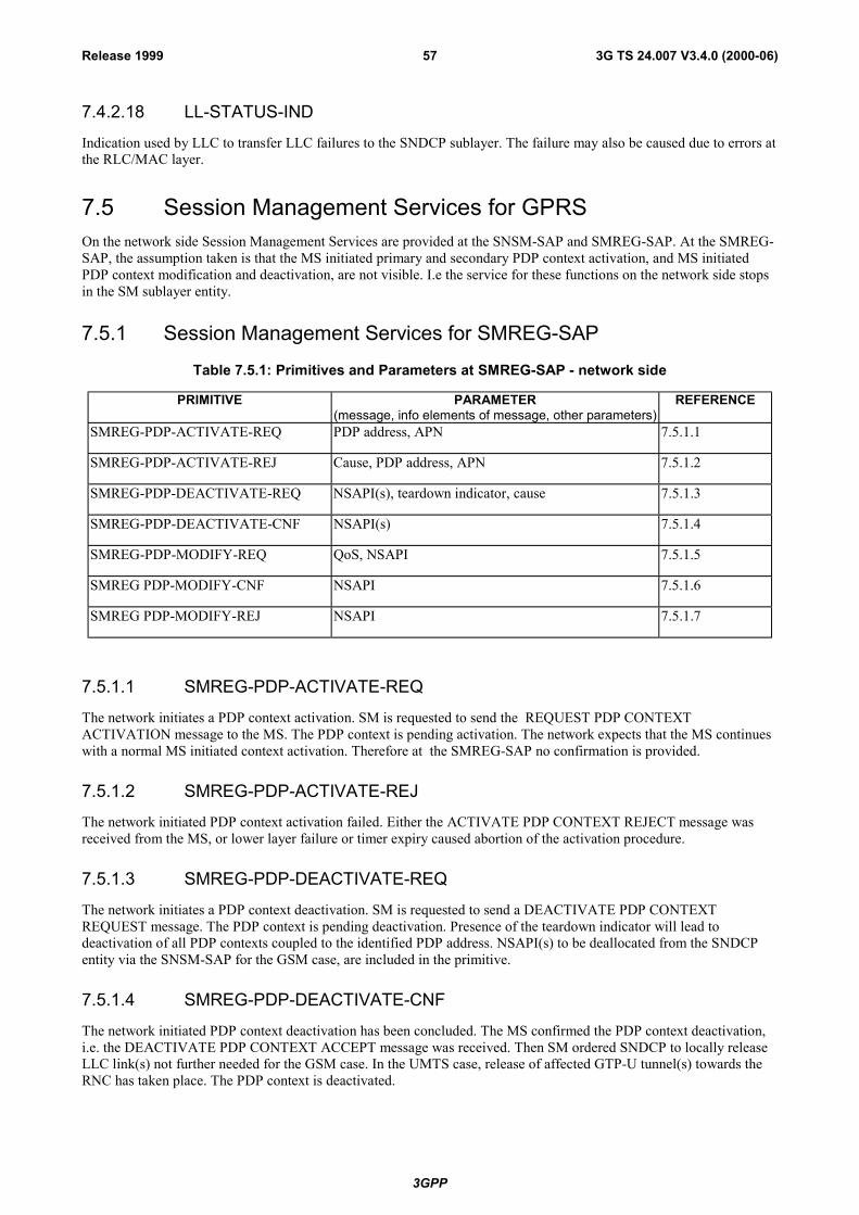
3GPP
3G TS 24.007 V3.4.0 (2000-06)57Release 1999
7.4.2.18 LL-STATUS-IND
Indication used by LLC to transfer LLC failures to the SNDCP sublayer. The failure may also be caused due to errors atthe RLC/MAC layer.
7.5 Session Management Services for GPRSOn the network side Session Management Services are provided at the SNSM-SAP and SMREG-SAP. At the SMREG-SAP, the assumption taken is that the MS initiated primary and secondary PDP context activation, and MS initiatedPDP context modification and deactivation, are not visible. I.e the service for these functions on the network side stopsin the SM sublayer entity.
7.5.1 Session Management Services for SMREG-SAP
Table 7.5.1: Primitives and Parameters at SMREG-SAP - network side
PRIMITIVE PARAMETER(message, info elements of message, other parameters)
REFERENCE
SMREG-PDP-ACTIVATE-REQ PDP address, APN 7.5.1.1
SMREG-PDP-ACTIVATE-REJ Cause, PDP address, APN 7.5.1.2
SMREG-PDP-DEACTIVATE-REQ NSAPI(s), teardown indicator, cause 7.5.1.3
SMREG-PDP-DEACTIVATE-CNF NSAPI(s) 7.5.1.4
SMREG-PDP-MODIFY-REQ QoS, NSAPI 7.5.1.5
SMREG PDP-MODIFY-CNF NSAPI 7.5.1.6
SMREG PDP-MODIFY-REJ NSAPI 7.5.1.7
7.5.1.1 SMREG-PDP-ACTIVATE-REQ
The network initiates a PDP context activation. SM is requested to send the REQUEST PDP CONTEXTACTIVATION message to the MS. The PDP context is pending activation. The network expects that the MS continueswith a normal MS initiated context activation. Therefore at the SMREG-SAP no confirmation is provided.
7.5.1.2 SMREG-PDP-ACTIVATE-REJ
The network initiated PDP context activation failed. Either the ACTIVATE PDP CONTEXT REJECT message wasreceived from the MS, or lower layer failure or timer expiry caused abortion of the activation procedure.
7.5.1.3 SMREG-PDP-DEACTIVATE-REQ
The network initiates a PDP context deactivation. SM is requested to send a DEACTIVATE PDP CONTEXTREQUEST message. The PDP context is pending deactivation. Presence of the teardown indicator will lead todeactivation of all PDP contexts coupled to the identified PDP address. NSAPI(s) to be deallocated from the SNDCPentity via the SNSM-SAP for the GSM case, are included in the primitive.
7.5.1.4 SMREG-PDP-DEACTIVATE-CNF
The network initiated PDP context deactivation has been concluded. The MS confirmed the PDP context deactivation,i.e. the DEACTIVATE PDP CONTEXT ACCEPT message was received. Then SM ordered SNDCP to locally releaseLLC link(s) not further needed for the GSM case. In the UMTS case, release of affected GTP-U tunnel(s) towards theRNC has taken place. The PDP context is deactivated.

3GPP
3G TS 24.007 V3.4.0 (2000-06)58Release 1999
7.5.1.5 SMREG-PDP-MODIFY-REQ
The network initiates a modification of the PDP context. SM is requested to send a MODIFY PDP CONTEXTREQUEST message to the MS. The PDP context is pending modification.
7.5.1.6 SMREG-PDP-MODIFY-CNF
The PDP context modification has been concluded. The MS confirmed he PDP context modification, i.e. the MODIFYPDP CONTEXT ACCEPT message was received. Then, for the GSM case, SM ordered SNDCP to adjust the affectedLLC link as required. For the UMTS case, RAB properties were updated as required. The PDP context is modified.
7.5.1.7 SMREG-PDP-MODIFY-REJ
The PDP context modification has been rejected. Due to timer expiry or lower layer failure the modification procedurehas been aborted.
7.5.2 Session Management Services for SNSM-SAPThe SNSM-SAP service primitives are defined in GSM 04.65 [12a].
7.6 Location services at the Network sideThe location services (initiation of location measurements at the network) are provided at the service access pointMNLCS-SAP. The service provided by the CM sublayer to support the location services is defined in GSM 04.71.
7.6.1 Service state diagramThe primitives provided by the call independent Location Services Support entity and the transitions between permittedstates are shown in the service graph of figure 7.6 below.
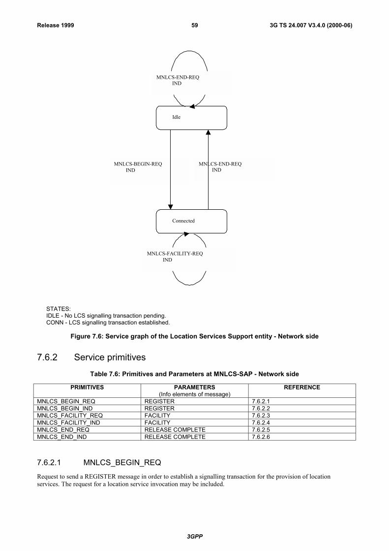
3GPP
3G TS 24.007 V3.4.0 (2000-06)59Release 1999
Connected
Idle
MNLCS-BEGIN-REQ IND
MNLCS-END-REQ IND
MNLCS-END-REQ IND
MNLCS-FACILITY-REQ IND
STATES:IDLE - No LCS signalling transaction pending.CONN - LCS signalling transaction established.
Figure 7.6: Service graph of the Location Services Support entity - Network side
7.6.2 Service primitives
Table 7.6: Primitives and Parameters at MNLCS-SAP - Network side
PRIMITIVES PARAMETERS(Info elements of message)
REFERENCE
MNLCS_BEGIN_REQ REGISTER 7.6.2.1MNLCS_BEGIN_IND REGISTER 7.6.2.2MNLCS_FACILITY_REQ FACILITY 7.6.2.3MNLCS_FACILITY_IND FACILITY 7.6.2.4MNLCS_END_REQ RELEASE COMPLETE 7.6.2.5MNLCS_END_IND RELEASE COMPLETE 7.6.2.6
7.6.2.1 MNLCS_BEGIN_REQ
Request to send a REGISTER message in order to establish a signalling transaction for the provision of locationservices. The request for a location service invocation may be included.

3GPP
3G TS 24.007 V3.4.0 (2000-06)60Release 1999
7.6.2.2 MNLCS_BEGIN_IND
Receipt of a REGISTER message, a signalling transaction is established for the provision of location services. Theindication of a location service invocation may be included.
7.6.2.3 MNLCS_FACILITY_REQ
Request to send a FACILITY message for the provision of a location service facility.
7.6.2.4 MNLCS_FACILITY_IND
Receipt of a FACILITY message, a location service facility has been requested.
7.6.2.5 MNLCS_END_REQ
Request to send a RELEASE COMPLETE message in order to release the signalling transaction by sending aRELEASE COMPLETE message. The request for transfer of a location service facility may be included.
7.6.2.6 MNLCS_END_IND
Indication that the signalling transaction has been released after receipt of a RELEASE COMPLETE message. Theindication of a location service facility may be included.
8 Services assumed from signalling layers 1 and 2The services provided by layer 2 are defined in detail in GSM 04.05. A short summary is given below.
In addition, layer 1 communicates directly with layer 3 for information transfer related to channel management and tomeasurement control. See section 8.5 below.
8.1 PriorityMessages from layer 3 can be sent with:
- no priority;
i.e. the messages are sent in first-in-first-out order;
- priority;
i.e. a message with this indication is sent as early as possible by layer 2.
8.2 Unacknowledged information transferTransfer of unacknowledged information using the primitives DL_UNIT_DATA_ REQUEST/INDICATION.
8.3 Acknowledged information transferTransfer of information in multiframe acknowledged mode including:
- establishment of data link connection between L3 entities;
- transfer of information in acknowledged mode;
- release of the data link connection.
The primitives associated with acknowledged information transfer are:

3GPP
3G TS 24.007 V3.4.0 (2000-06)61Release 1999
- DL_ESTABLISH_REQUEST/INDICATION/CONFIRM for establishment of acknowledged mode;
- DL_DATA_REQUEST/INDICATION for requesting the transmission of a message unit and for indicating thereception of a message unit;
- DL_SUSPEND_REQUEST/DL_RELEASE_CONFIRM for requesting and confirming the suspension of theacknowledged information transfer in the MS upon channel change;
- DL_RESUME_REQUEST/DL_ESTABLISH_CONFIRM for requesting and confirming the resumption of theacknowledged information transfer in the MS after suspension at channel change;
- DL_RELEASE_REQUEST/INDICATION/CONFIRM for the termination of acknowledged mode operation;
- DL_RECONNECT_REQUEST for requesting the re-establishment of acknowledged information transfer in theMS on the old channel after channel change failure.
8.4 Random accessThe transmission/reception of a random access burst is controlled by the primitivesDL_RANDOM_ACCESS_REQUEST/INDICATION/CONFIRM.
8.5 Channel management and measurementsThe management of channels, i.e. their activation, deactivation, configuration, deconfiguration, through-connection anddisconnection is controlled by the RR sublayer in layer 3. The measurements performed by the physical layer are alsocontrolled by the RR sublayer of layer 3 and they are reported to layer 3.
These functions use the primitives MPH_INFORMATION_REQUEST/INDICATION/CONFIRMATION.
9 Interlayer service interfaces on the MS sideIn addition to the services described in this clause, the RR entity and MM entity also provide services to CM entitieswhich don't belong to the functional blocks of CC, SMS, and SS. (For example, the RR entity provides service to GroupCall and Broadcast Call entities.) These services are not further described in this clause.
9.1 Services provided by the Radio Resource Managemententity
The Radio Resource Management (RR) sublayer provides a service to the Mobility Management entity (MM).
The RR services are used for:
- establishing control channel connections;
- releasing control channel connections;
- control-data transfer.
The Radio Resource Management services are represented by the RR-service primitives.

3GPP
3G TS 24.007 V3.4.0 (2000-06)62Release 1999
MS side Network side
MobilityManagementsublayer
Radio ResourceManagementsublayer
RR-primitives
RR sublayer peer-to-peer protocol
RRSAP
Figure 9.1: Services provided at RR-SAP - MS side
9.1.1 Service state diagramThe primitives provided by the Radio Resource Management entity and the transition between permitted states areshown in figure 9.2.
ALLSTATES
IDLE
CONPEND
DEDI-CATED
RR-EST-REQ RR-UNIT-DATA-IND
RR-ABORT-IND
RR-EST-IND
RR-REL-INDRR-ABORT-REQ
RR-EST-CNFRR-SYNC-IND(ciph)(res ass)(channel mode modify)
RR-DATA-REQ-INDRR-UNIT-DATA-IND
Figure 9.2: Service graph of the Radio Resource Management - MS side
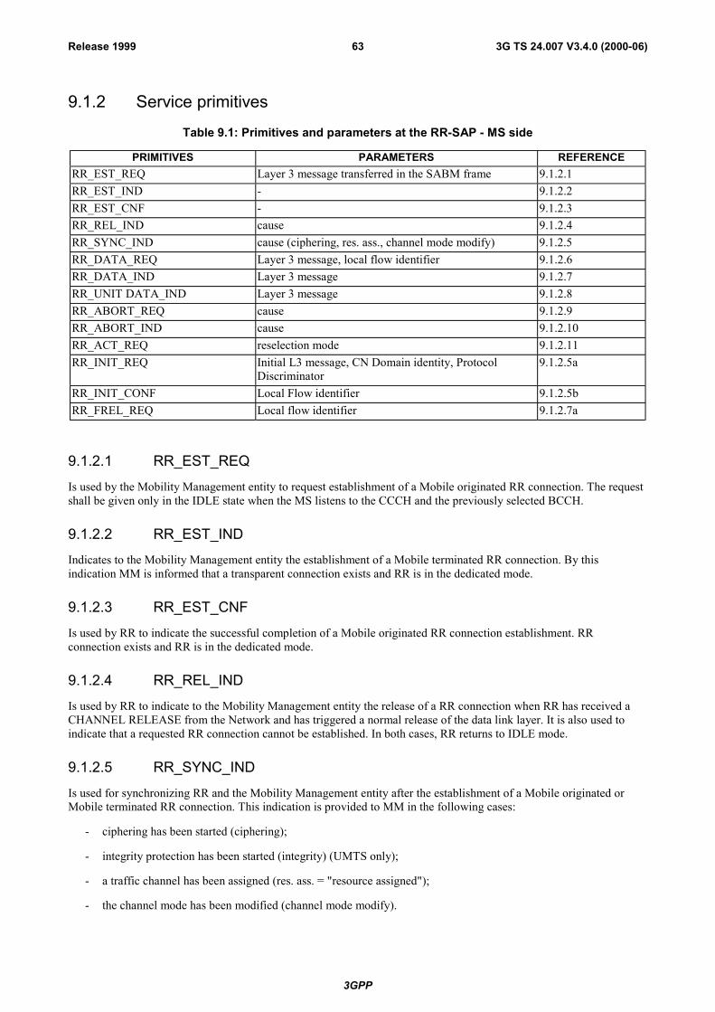
3GPP
3G TS 24.007 V3.4.0 (2000-06)63Release 1999
9.1.2 Service primitives
Table 9.1: Primitives and parameters at the RR-SAP - MS side
PRIMITIVES PARAMETERS REFERENCERR_EST_REQ Layer 3 message transferred in the SABM frame 9.1.2.1RR_EST_IND - 9.1.2.2RR_EST_CNF - 9.1.2.3RR_REL_IND cause 9.1.2.4RR_SYNC_IND cause (ciphering, res. ass., channel mode modify) 9.1.2.5RR_DATA_REQ Layer 3 message, local flow identifier 9.1.2.6RR_DATA_IND Layer 3 message 9.1.2.7RR_UNIT DATA_IND Layer 3 message 9.1.2.8RR_ABORT_REQ cause 9.1.2.9RR_ABORT_IND cause 9.1.2.10RR_ACT_REQ reselection mode 9.1.2.11RR_INIT_REQ Initial L3 message, CN Domain identity, Protocol
Discriminator9.1.2.5a
RR_INIT_CONF Local Flow identifier 9.1.2.5bRR_FREL_REQ Local flow identifier 9.1.2.7a
9.1.2.1 RR_EST_REQ
Is used by the Mobility Management entity to request establishment of a Mobile originated RR connection. The requestshall be given only in the IDLE state when the MS listens to the CCCH and the previously selected BCCH.
9.1.2.2 RR_EST_IND
Indicates to the Mobility Management entity the establishment of a Mobile terminated RR connection. By thisindication MM is informed that a transparent connection exists and RR is in the dedicated mode.
9.1.2.3 RR_EST_CNF
Is used by RR to indicate the successful completion of a Mobile originated RR connection establishment. RRconnection exists and RR is in the dedicated mode.
9.1.2.4 RR_REL_IND
Is used by RR to indicate to the Mobility Management entity the release of a RR connection when RR has received aCHANNEL RELEASE from the Network and has triggered a normal release of the data link layer. It is also used toindicate that a requested RR connection cannot be established. In both cases, RR returns to IDLE mode.
9.1.2.5 RR_SYNC_IND
Is used for synchronizing RR and the Mobility Management entity after the establishment of a Mobile originated orMobile terminated RR connection. This indication is provided to MM in the following cases:
- ciphering has been started (ciphering);
- integrity protection has been started (integrity) (UMTS only);
- a traffic channel has been assigned (res. ass. = "resource assigned");
- the channel mode has been modified (channel mode modify).

3GPP
3G TS 24.007 V3.4.0 (2000-06)64Release 1999
9.1.2.5a RR_INIT_REQ
For UMTS, it is used by the Mobility Management entity to request RRC to establish a new signalling flow between theUE and the Core Network via an existing RRC connection. It includes:
- the Protocol Discriminator and CN Domain Identity requested in the L3 (control data) message;
- an associated L3 message.
The primitive is invoked for every new PD/TI upper layer transaction.
9.1.2.5b RR_INIT_CONF
For UMTS, it is used by the RRC entity to inform the MM entity of the "local flow identifier" allocated to the requestedsignalling flow through the RR_INIT_REQ primitive.
9.1.2.6 RR_DATA_REQ
Is used by the Mobility Management entity to send control data to its peer entity on the Network side via an existing RRconnection.
For UMTS, RR_DATA_REQ is used to send all subsequent control data (L3) messages belonging to an on-goingsignalling flow. It includes:
- associated L3 message,
- the "local flow identifier" allocated by the RRC entity, identifying the signalling flow the control data messagebelongs to.
9.1.2.7 RR_DATA_IND
Is used by RR to indicate control-data, which has been received from its peer entity on the Network side via an existingRR connection.
For UMTS, RR_DATA_IND is also used to indicate whether control-data has been:
- successfully integrity checked;
- unsuccessfully integrity checked;
- received with no integrity protection.
9.1.2.7a RR_FREL_REQ
For UMTS, it is used by MM to inform RRC that it can release a local flow identifier and the corresponding signallingflow.
This primitive is invoked by MM when the corresponding signalling flow is released by upper layers.
9.1.2.8 RR_UNIT_DATA_IND
Is used by RR to provide MM with system info. The system info is received on the current BCCH if RR is in the IDLEstate. If a RR connection has been established, the system info is received on the SACCH.
9.1.2.9 RR_ABORT_REQ
Request to abort an existing RR connection or a RR connection in progress. The data link, if already established, shallbe released by a normal release procedure (DISC/UA) initiated by the MS. This is the only way the MS can trigger therelease of a RR connection in case of exceptional conditions. The RR returns to the IDLE state.
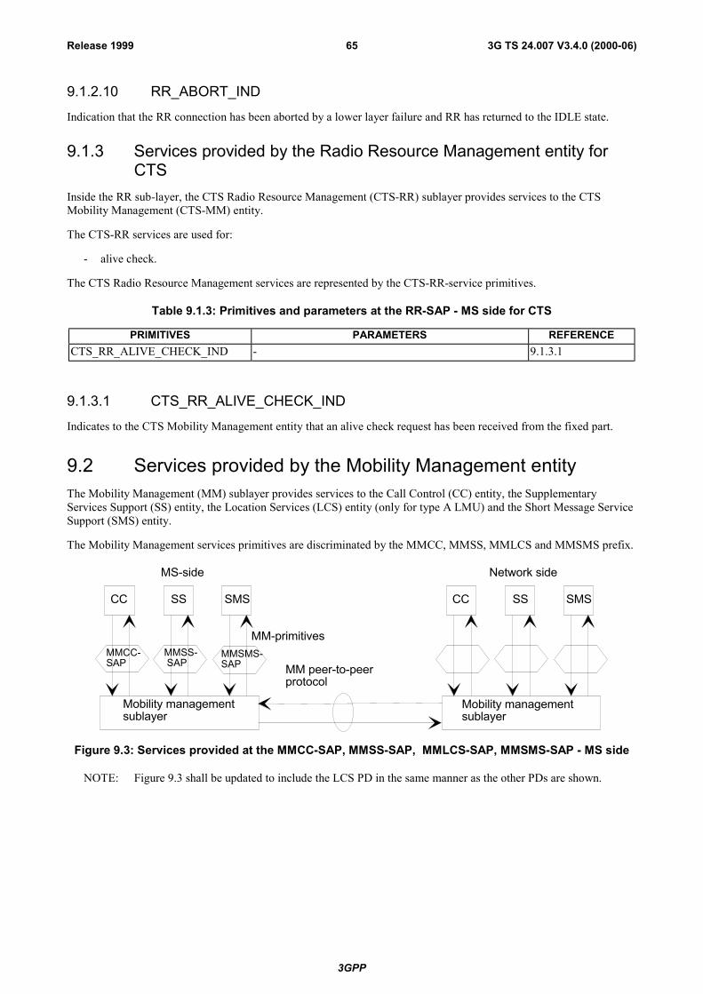
3GPP
3G TS 24.007 V3.4.0 (2000-06)65Release 1999
9.1.2.10 RR_ABORT_IND
Indication that the RR connection has been aborted by a lower layer failure and RR has returned to the IDLE state.
9.1.3 Services provided by the Radio Resource Management entity forCTS
Inside the RR sub-layer, the CTS Radio Resource Management (CTS-RR) sublayer provides services to the CTSMobility Management (CTS-MM) entity.
The CTS-RR services are used for:
- alive check.
The CTS Radio Resource Management services are represented by the CTS-RR-service primitives.
Table 9.1.3: Primitives and parameters at the RR-SAP - MS side for CTS
PRIMITIVES PARAMETERS REFERENCECTS_RR_ALIVE_CHECK_IND - 9.1.3.1
9.1.3.1 CTS_RR_ALIVE_CHECK_IND
Indicates to the CTS Mobility Management entity that an alive check request has been received from the fixed part.
9.2 Services provided by the Mobility Management entityThe Mobility Management (MM) sublayer provides services to the Call Control (CC) entity, the SupplementaryServices Support (SS) entity, the Location Services (LCS) entity (only for type A LMU) and the Short Message ServiceSupport (SMS) entity.
The Mobility Management services primitives are discriminated by the MMCC, MMSS, MMLCS and MMSMS prefix.
CC SS SMS CC SS SMS
MMCC-SAP
MMSS- SAP
MMSMS-SAP
Mobility managementsublayer
Mobility managementsublayer
MM-primitives
MM peer-to-peerprotocol
MS-side Network side
Figure 9.3: Services provided at the MMCC-SAP, MMSS-SAP, MMLCS-SAP, MMSMS-SAP - MS side
NOTE: Figure 9.3 shall be updated to include the LCS PD in the same manner as the other PDs are shown.
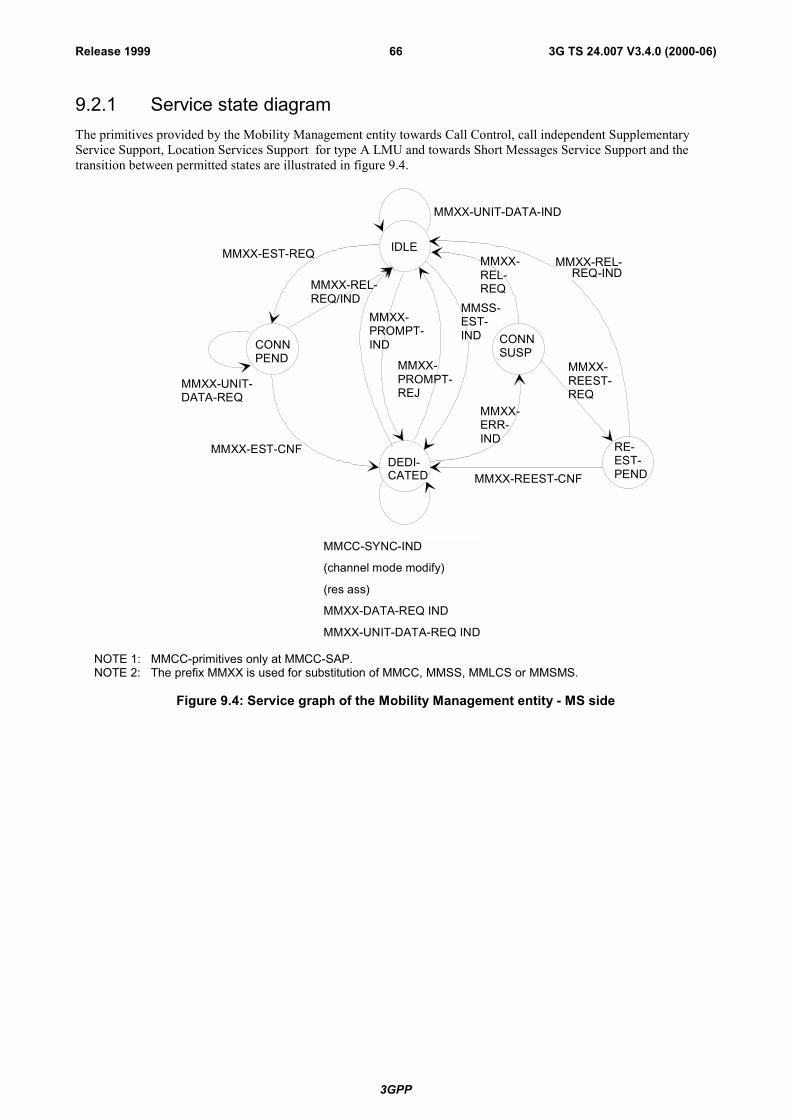
3GPP
3G TS 24.007 V3.4.0 (2000-06)66Release 1999
9.2.1 Service state diagramThe primitives provided by the Mobility Management entity towards Call Control, call independent SupplementaryService Support, Location Services Support for type A LMU and towards Short Messages Service Support and thetransition between permitted states are illustrated in figure 9.4.
IDLE
DEDI-CATED
MMXX-UNIT-DATA-IND
MMXX-REL- REQ-IND
MMXX-REEST-CNF
MMXX-REL-REQ/IND
MMXX-EST-REQ
MMXX-EST-CNF
MMCC-SYNC-IND
(channel mode modify)
(res ass)
MMXX-DATA-REQ IND
MMXX-UNIT-DATA-REQ IND
MMXX-PROMPT-IND
MMXX-PROMPT-REJ
MMXX-REL-REQ
MMSS-EST-IND
MMXX-REEST-REQ
MMXX-ERR-IND
MMXX-UNIT-DATA-REQ
CONNPEND
CONNSUSP
RE-EST-PEND
NOTE 1: MMCC-primitives only at MMCC-SAP.NOTE 2: The prefix MMXX is used for substitution of MMCC, MMSS, MMLCS or MMSMS.
Figure 9.4: Service graph of the Mobility Management entity - MS side
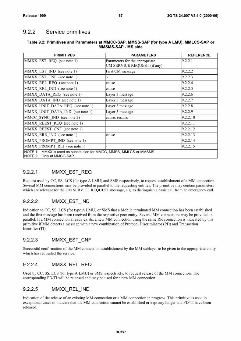
3GPP
3G TS 24.007 V3.4.0 (2000-06)67Release 1999
9.2.2 Service primitives
Table 9.2: Primitives and Parameters at MMCC-SAP, MMSS-SAP (for type A LMU), MMLCS-SAP orMMSMS-SAP - MS side
PRIMITIVES PARAMETERS REFERENCEMMXX_EST_REQ (see note 1) Parameters for the appropriate
CM SERVICE REQUEST (if any)9.2.2.1
MMXX_EST_IND (see note 1) First CM message 9.2.2.2MMXX_EST_CNF (see note 1) - 9.2.2.3MMXX_REL_REQ (see note 1) cause 9.2.2.4MMXX_REL_IND (see note 1) cause 9.2.2.5MMXX_DATA_REQ (see note 1) Layer 3 message 9.2.2.6MMXX_DATA_IND (see note 1) Layer 3 message 9.2.2.7MMXX_UNIT_DATA_REQ (see note 1) Layer 3 message 9.2.2.8MMXX_UNIT_DATA_IND (see note 1) Layer 3 message 9.2.2.9MMCC_SYNC_IND (see note 2) cause: res.ass 9.2.2.10MMXX_REEST_REQ (see note 1) 9.2.2.11MMXX_REEST_CNF (see note 1) 9.2.2.12MMXX_ERR_IND (see note 1) cause 9.2.2.13MMXX_PROMPT_IND (see note 1) - 9.2.2.14MMXX_PROMPT_REJ (see note 1) - 9.2.2.15NOTE 1: MMXX is used as substitution for MMCC, MMSS, MMLCS or MMSMS.NOTE 2: Only at MMCC-SAP.
9.2.2.1 MMXX_EST_REQ
Request used by CC, SS, LCS (for type A LMU) and SMS respectively, to request establishment of a MM connection.Several MM connections may be provided in parallel to the requesting entities. The primitive may contain parameterswhich are relevant for the CM SERVICE REQUEST message, e.g. to distinguish a basic call from an emergency call.
9.2.2.2 MMXX_EST_IND
Indication to CC, SS, LCS (for type A LMU) or SMS that a Mobile terminated MM connection has been establishedand the first message has been received from the respective peer entity. Several MM connections may be provided inparallel. If a MM connection already exists, a new MM connection using the same RR connection is indicated by thisprimitive if MM detects a message with a new combination of Protocol Discriminator (PD) and TransactionIdentifier (TI).
9.2.2.3 MMXX_EST_CNF
Successful confirmation of the MM connection establishment by the MM sublayer to be given to the appropriate entitywhich has requested the service.
9.2.2.4 MMXX_REL_REQ
Used by CC, SS, LCS (for type A LMU) or SMS respectively, to request release of the MM connection. Thecorresponding PD/TI will be released and may be used for a new MM connection.
9.2.2.5 MMXX_REL_IND
Indication of the release of an existing MM connection or a MM connection in progress. This primitive is used inexceptional cases to indicate that the MM connection cannot be established or kept any longer and PD/TI have beenreleased.
3GPP
3G TS 24.007 V3.4.0 (2000-06)68Release 1999
9.2.2.6 MMXX_DATA_REQ
Request used by the CC, SS or SMS entities for acknowledged control-data transmission.
9.2.2.7 MMXX_DATA_IND
Indication used by MM to transfer the received acknowledged control-data to the CC, SS, LCS (for type A LMU) orSMS entities.
9.2.2.8 MMXX_UNIT_DATA_REQ
Request used by the CC, SS, LCS (for type A LMU) or SMS entities for unacknowledged control-data transmission.
9.2.2.9 MMXX_UNIT_DATA_IND
Indication used by MM to transfer the received unacknowledged control-data to the CC, SS, LCS or SMS entities.
9.2.2.10 MMCC_SYNC_IND
Indication that a dedicated channel assignment has been performed and/or the channel mode has been changed (onlytowards the CC entity).
9.2.2.11 MMXX_REEST_REQ
Request to establish a MM connection which has been interrupted by a lower layer failure. The interruption must havebeen indicated by MMXX_ERR_IND.
9.2.2.12 MMXX_REEST_CNF
Confirmation of the successful re-establishment of the MM connection. The MM connection will continue with PD/TIas it had before.
9.2.2.13 MMXX_ERR_IND
Indication of a lower layer failure interrupting the MM connection. The PD/TI are still kept by MM. In case of paralleltransactions this indication is passed to all CM entities for which a MM connection has been established. It is left to thedecision of the appropriate CM entity to either request the re-establishment of the MM connection byMMXX_REEST_REQ or to release it by MMXX_REL_REQ.
9.2.2.14 MMXX_PROMPT_IND
Indication given by MM to inform of the completion of the MM connection to the CC, SS, LCS (for type A LMU) orSMS entities for a mobile station which supports �Network Initiated MO CM Connection Request�.
9.2.2.15 MMXX_PROMPT_REJ
Response to the MMXX_PROMPT_IND indication to the MM entity in a mobile station which supports �NetworkInitiated MO CM Connection Request� in case when it is impossible to establish the prompted CM connection e.g. dueto lack of free transaction identifiers.

3GPP
3G TS 24.007 V3.4.0 (2000-06)69Release 1999
9.3 Services provided by radio resource management entity forGPRS services
9.3.1 Service primitives for GRR-SAPThe GRR-SAP service primitives are defined in GSM 04.64 [11a]
[[Table 9.3.1, and chapters 9.3.1.1 - 9.3.1.5 are Void]
9.3.2 Service primitives for GMMRR-SAP
Table 9.3.2: Primitives and Parameters at GMMRR-SAP - MS side
PRIMITIVE PARAMETER(message, info elements of message, other parameters)
REFERENCE
GMMRR-ASSIGN-REQ newTLLI 9.3.2.1
GMMRR-PAGE-IND TLLI 9.3.2.2
9.3.2.1 GMMRR-ASSIGN-REQ
A new TLLI is assigned to the RR sublayer.
9.3.2.2 GMMRR-PAGE-IND
A RR-paging message has been received by the RR sublayer.
9.4 Services provided by the LLC entity for GPRS servicesThis subclause is informative, the service primitives are defined in GSM 04.64 [11a]. They are included here to providea complete overview of the radio interface protocol architecture.
9.4.1 Service primitives for LLGMM-SAP
Table 9.4.1: Primitives and parameters at LLGMM-SAP - MS side
PRIMITIVE PARAMETER(message, info elements of message, other parameters)
REFERENCE
LLGMM-ASSIGN-REQ oldTLLI, newTLLI, Kc, RAND, Ciphering Algorithm 9.4.1.1
LLGMM-TRIGGER-REQ Cause 9.4.1.2
LLGMM-TRIGGER-IND - 9.4.1.3
LLGMM-SUSPEND-REQ TLLI 9.4.1.4
LLGMM-RESUME-REQ TLLI 9.4.1.5
LLGMM-WINDOW-REQ TLLI, old SGSN�s V(R) per SAPI 9.4.1.6
LLGMM-WINDOW-CNF TLLI, actual MS�s LLC�s V(R) per SAPI 9.4.1.7
LL-UNITDATA-REQ TLLI, GMM-PDU, protect, cipher 9.4.1.8
LL-UNITDATA-IND TLLI, GMM-PDU, cipher 9.4.1.9
LLGMM-STATUS-IND TLLI, cause 9.4.1.10
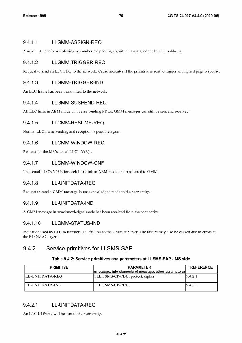
3GPP
3G TS 24.007 V3.4.0 (2000-06)70Release 1999
9.4.1.1 LLGMM-ASSIGN-REQ
A new TLLI and/or a ciphering key and/or a ciphering algorithm is assigned to the LLC sublayer.
9.4.1.2 LLGMM-TRIGGER-REQ
Request to send an LLC PDU to the network. Cause indicates if the primitive is sent to trigger an implicit page response.
9.4.1.3 LLGMM-TRIGGER-IND
An LLC frame has been transmitted to the network.
9.4.1.4 LLGMM-SUSPEND-REQ
All LLC links in ABM mode will cease sending PDUs. GMM messages can still be sent and received.
9.4.1.5 LLGMM-RESUME-REQ
Normal LLC frame sending and reception is possible again.
9.4.1.6 LLGMM-WINDOW-REQ
Request for the MS�s actual LLC�s V(R)s.
9.4.1.7 LLGMM-WINDOW-CNF
The actual LLC�s V(R)s for each LLC link in ABM mode are transferred to GMM.
9.4.1.8 LL-UNITDATA-REQ
Request to send a GMM message in unacknowledged mode to the peer entity.
9.4.1.9 LL-UNITDATA-IND
A GMM message in unacknowledged mode has been received from the peer entity.
9.4.1.10 LLGMM-STATUS-IND
Indication used by LLC to transfer LLC failures to the GMM sublayer. The failure may also be caused due to errors atthe RLC/MAC layer.
9.4.2 Service primitives for LLSMS-SAP
Table 9.4.2: Service primitives and parameters at LLSMS-SAP - MS side
PRIMITIVE PARAMETER(message, info elements of message, other parameters)
REFERENCE
LL-UNITDATA-REQ TLLI, SMS-CP-PDU, protect, cipher 9.4.2.1
LL-UNITDATA-IND TLLI, SMS-CP-PDU, 9.4.2.2
9.4.2.1 LL-UNITDATA-REQ
An LLC UI frame will be sent to the peer entity.

3GPP
3G TS 24.007 V3.4.0 (2000-06)71Release 1999
9.4.2.2 LL-UNITDATA-IND
An LLC UI frame has been received from the peer entity.
9.5 Services provided by the GMM for GPRS servicesThe GPRS Mobility Management (GMM) sublayer provides services to the Session Management (SM) entity and theShort Message Service Support (GSMS) entity for message transfer.
9.5.1 Service primitives for GMMSM-SAPSession management services may request GPRS service registration before activating a PDP context.

3GPP
3G TS 24.007 V3.4.0 (2000-06)72Release 1999
Table 9.5.1: Primitives and parameters at GMMSM-SAP - MS side
PRIMITIVE PARAMETER(message, info elements of message, other
parameters)
REFERENCE
GMMSM-ESTABLISH-REQ - 9.5.1.1
GMMSM-ESTABLISH-CNF - 9.5.1.2
GMMSM-ESTABLISH-REJ cause 9.5.1.3
GMMSM-RELEASE-IND - 9.5.1.4
GMMSM-UNITDATA-REQ SM-PDU 9.5.1.5
GMMSM-UNITDATA-IND SM-PDU 9.5.1.6
9.5.1.1 GMMSM-ESTABLISH-REQ
Request from Session Management to send an ATTACH REQUEST message to the network to setup a GMMconnection. The request is only performed in case the MS is not already attached. The GPRS attach is then indirectlycaused by a requested PDP context activation.
9.5.1.2 GMMSM-ESTABLISH-CNF
The network has send the ATTACH ACCEPT message to the MS, the indirect attach was successful. Now sessionmanagement can proceed with PDP context activation.
9.5.1.3 GMMSM-ESTABLISH-REJ
The network has rejected the attach. The MS has received the ATTACH REJECT message.
9.5.1.4 GMMSM-RELEASE-IND
The GPRS mobility management informs the session management that the MS has been GPRS detached, e.g. by timerexpiry, and therefore the PDP contexts are not valid anymore.
9.5.1.5 GMMSM-UNITDATA-REQ
The GMM is requested to forward a SM PDU to LLC in order to send it in unacknowledged more to the peer entity.
9.5.1.6 GMMSM-UNITDATA-IND
The GMM forwards a SM PDU, which has been received in unacknowledged mode via LLC from the peer entity.
9.5.2 Void
9.5.3 Service primitives for GMMSMS-SAPThe Short Message entity may request from the GMM entity the GMM IMSI registration state before an MO SMStransmission is initiated.
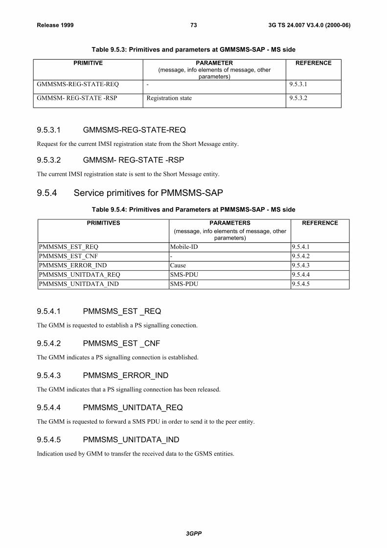
3GPP
3G TS 24.007 V3.4.0 (2000-06)73Release 1999
Table 9.5.3: Primitives and parameters at GMMSMS-SAP - MS side
PRIMITIVE PARAMETER(message, info elements of message, other
parameters)
REFERENCE
GMMSMS-REG-STATE-REQ - 9.5.3.1
GMMSM- REG-STATE -RSP Registration state 9.5.3.2
9.5.3.1 GMMSMS-REG-STATE-REQ
Request for the current IMSI registration state from the Short Message entity.
9.5.3.2 GMMSM- REG-STATE -RSP
The current IMSI registration state is sent to the Short Message entity.
9.5.4 Service primitives for PMMSMS-SAP
Table 9.5.4: Primitives and Parameters at PMMSMS-SAP - MS side
PRIMITIVES PARAMETERS(message, info elements of message, other
parameters)
REFERENCE
PMMSMS_EST_REQ Mobile-ID 9.5.4.1PMMSMS_EST_CNF - 9.5.4.2PMMSMS_ERROR_IND Cause 9.5.4.3PMMSMS_UNITDATA_REQ SMS-PDU 9.5.4.4PMMSMS_UNITDATA_IND SMS-PDU 9.5.4.5
9.5.4.1 PMMSMS_EST _REQ
The GMM is requested to establish a PS signalling conection.
9.5.4.2 PMMSMS_EST _CNF
The GMM indicates a PS signalling connection is established.
9.5.4.3 PMMSMS_ERROR_IND
The GMM indicates that a PS signalling connection has been released.
9.5.4.4 PMMSMS_UNITDATA_REQ
The GMM is requested to forward a SMS PDU in order to send it to the peer entity.
9.5.4.5 PMMSMS_UNITDATA_IND
Indication used by GMM to transfer the received data to the GSMS entities.
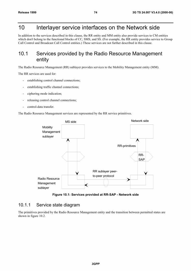
3GPP
3G TS 24.007 V3.4.0 (2000-06)74Release 1999
10 Interlayer service interfaces on the Network sideIn addition to the services described in this clause, the RR entity and MM entity also provide services to CM entitieswhich don't belong to the functional blocks of CC, SMS, and SS. (For example, the RR entity provides service to GroupCall Control and Broadcast Call Control entities.) These services are not further described in this clause.
10.1 Services provided by the Radio Resource Managemententity
The Radio Resource Management (RR) sublayer provides services to the Mobility Management entity (MM).
The RR services are used for:
- establishing control channel connections;
- establishing traffic channel connections;
- ciphering mode indication;
- releasing control channel connections;
- control-data transfer.
The Radio Resource Management services are represented by the RR service primitives.
MS side Network side
MobilityManagementsublayer
RR-SAP
RR-primitives
RR sublayer peer-to-peer protocol
Radio ResourceManagementsublayer
Figure 10.1: Services provided at RR-SAP - Network side
10.1.1 Service state diagramThe primitives provided by the Radio Resource Management entity and the transition between permitted states areshown in figure 10.2.

3GPP
3G TS 24.007 V3.4.0 (2000-06)75Release 1999
RR-UNIT-DATA-REQRR-REL-REQ IND
RR-REL-REQ IND
RR-ABORT-REQ INDRR-EST-IND
RR-SYNC-CNF Note 1
RR-EST-REQ
RR-REL-REQ IND
RR-ABOURT-REQ IND
RR-UNIT-DATA-REQ
RR-EST-CNF
IDLE
CONPEND
RR-SYNC-REQ(res ass)(ciph)(channel mode modify)
RR-DATA-REQ IND
RR-UNIT-DATA-REQ IND
RR-DATA-REQ IND RR-UNIT-DATA-REQ IND
STATES:IDLE: - No dedicated channel established.CONPEND: - Connection pending.DT1: - Data transfer 1, dedicated channel established.DT2: - Data transfer 2, dedicated channel established, ciphering mode set.
Figure 10.2: Service graph of the Radio Resource Management entity - Network side
10.1.2 Service primitives
Table 10.1: Primitives and Parameters at the RR-SAP - Network side
PRIMITIVES PARAMETERS REFERENCERR_EST_REQ Parameters for the Initial layer 3 message 10.1.2.1RR_EST_IND Initial layer 3 message 10.1.2.2RR_EST_CNF - 10.1.2.3RR_REL_REQ cause 10.1.2.4RR_REL_IND cause 10.1.2.5RR_SYNC_REQ cause (resource assign, ciphering) 10.1.2.6RR_SYNC_CNF cause (resource assign, ciphering) 10.1.2.7RR_DATA_REQ Layer 3 message 10.1.2.8RR_DATA_IND Layer 3 message 10.1.2.9RR_UNIT_DATA_REQ Layer 3 message 10.1.2.10RR_UNIT_DATA_IND Layer 3 message 10.1.2.11RR_ABORT_REQ cause 10.1.2.12RR_ABORT_IND cause 10.1.2.13
10.1.2.1 RR_EST_REQ
Request used by the Mobility Management entity to request establishment of control channel connections.
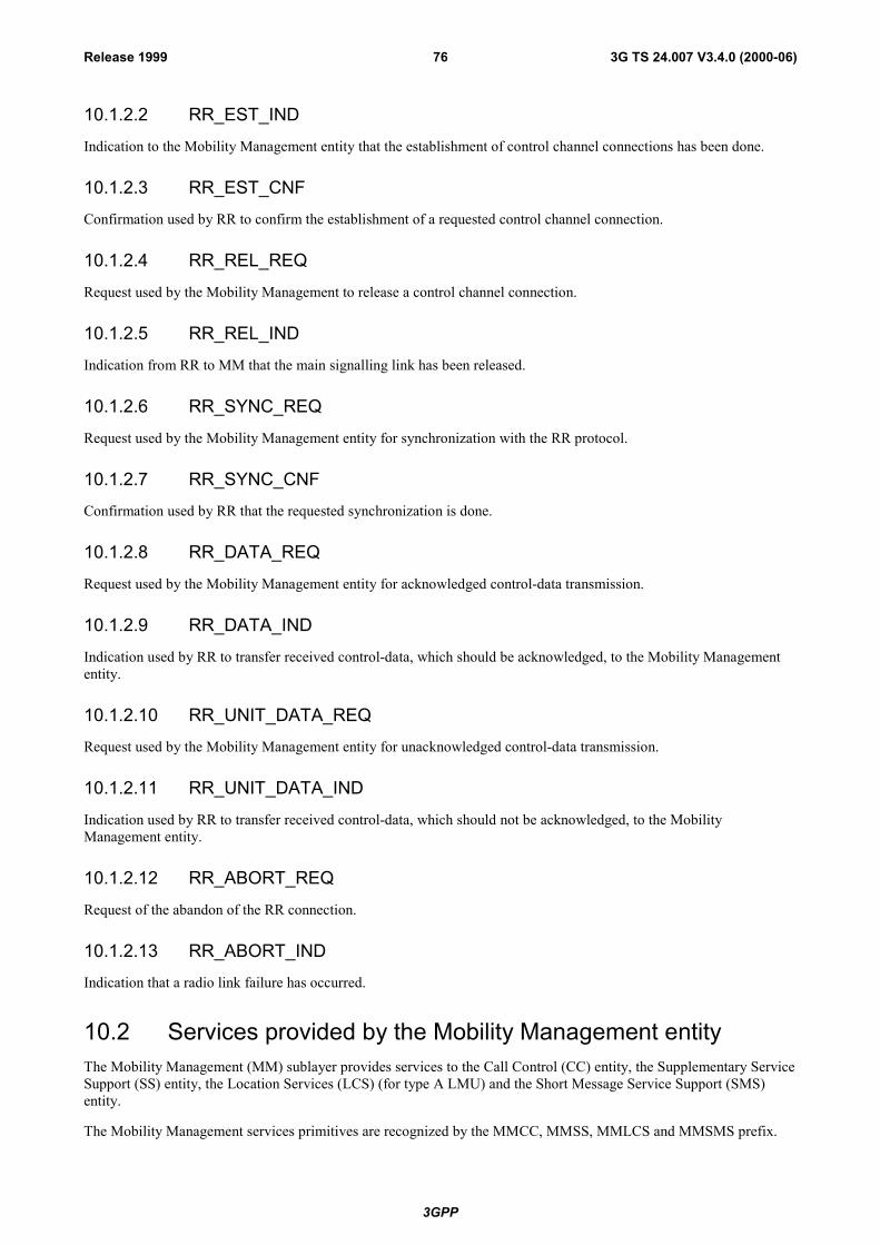
3GPP
3G TS 24.007 V3.4.0 (2000-06)76Release 1999
10.1.2.2 RR_EST_IND
Indication to the Mobility Management entity that the establishment of control channel connections has been done.
10.1.2.3 RR_EST_CNF
Confirmation used by RR to confirm the establishment of a requested control channel connection.
10.1.2.4 RR_REL_REQ
Request used by the Mobility Management to release a control channel connection.
10.1.2.5 RR_REL_IND
Indication from RR to MM that the main signalling link has been released.
10.1.2.6 RR_SYNC_REQ
Request used by the Mobility Management entity for synchronization with the RR protocol.
10.1.2.7 RR_SYNC_CNF
Confirmation used by RR that the requested synchronization is done.
10.1.2.8 RR_DATA_REQ
Request used by the Mobility Management entity for acknowledged control-data transmission.
10.1.2.9 RR_DATA_IND
Indication used by RR to transfer received control-data, which should be acknowledged, to the Mobility Managemententity.
10.1.2.10 RR_UNIT_DATA_REQ
Request used by the Mobility Management entity for unacknowledged control-data transmission.
10.1.2.11 RR_UNIT_DATA_IND
Indication used by RR to transfer received control-data, which should not be acknowledged, to the MobilityManagement entity.
10.1.2.12 RR_ABORT_REQ
Request of the abandon of the RR connection.
10.1.2.13 RR_ABORT_IND
Indication that a radio link failure has occurred.
10.2 Services provided by the Mobility Management entityThe Mobility Management (MM) sublayer provides services to the Call Control (CC) entity, the Supplementary ServiceSupport (SS) entity, the Location Services (LCS) (for type A LMU) and the Short Message Service Support (SMS)entity.
The Mobility Management services primitives are recognized by the MMCC, MMSS, MMLCS and MMSMS prefix.
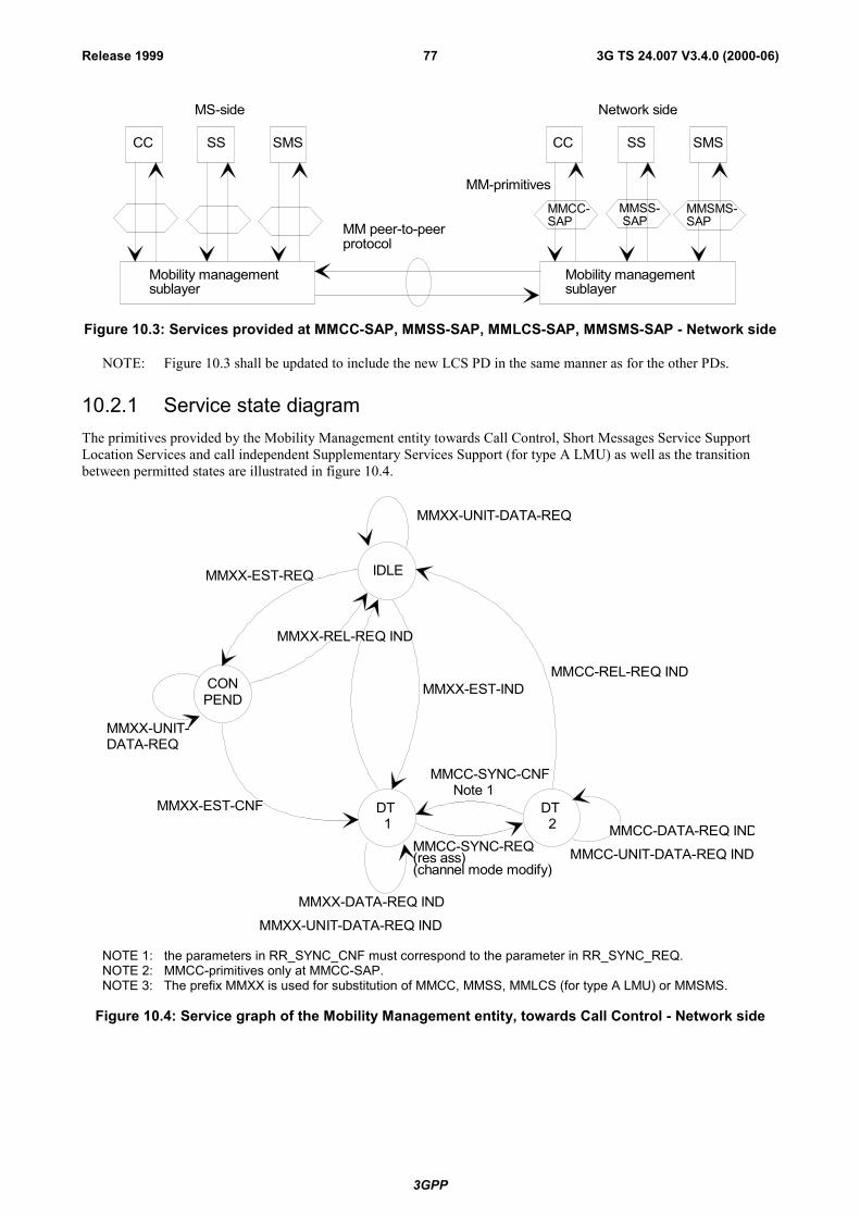
3GPP
3G TS 24.007 V3.4.0 (2000-06)77Release 1999
CC SS SMS CC SS SMS
MMCC-SAP
MMSS- SAP
MMSMS-SAP
Mobility managementsublayer
Mobility managementsublayer
MM-primitives
MM peer-to-peerprotocol
MS-side Network side
Figure 10.3: Services provided at MMCC-SAP, MMSS-SAP, MMLCS-SAP, MMSMS-SAP - Network side
NOTE: Figure 10.3 shall be updated to include the new LCS PD in the same manner as for the other PDs.
10.2.1 Service state diagramThe primitives provided by the Mobility Management entity towards Call Control, Short Messages Service SupportLocation Services and call independent Supplementary Services Support (for type A LMU) as well as the transitionbetween permitted states are illustrated in figure 10.4.
IDLE
CONPEND
MMXX-UNIT-DATA-REQ
MMCC-REL-REQ IND
MMXX-EST-REQ
MMXX-REL-REQ IND
MMXX-EST-IND
MMCC-SYNC-REQ(res ass)(channel mode modify)
MMXX-DATA-REQ INDMMXX-UNIT-DATA-REQ IND
MMCC-DATA-REQ INDMMCC-UNIT-DATA-REQ IND
MMXX-EST-CNF
MMXX-UNIT-DATA-REQ
DT 1
MMCC-SYNC-CNF Note 1
DT 2
NOTE 1: the parameters in RR_SYNC_CNF must correspond to the parameter in RR_SYNC_REQ.NOTE 2: MMCC-primitives only at MMCC-SAP.NOTE 3: The prefix MMXX is used for substitution of MMCC, MMSS, MMLCS (for type A LMU) or MMSMS.
Figure 10.4: Service graph of the Mobility Management entity, towards Call Control - Network side

3GPP
3G TS 24.007 V3.4.0 (2000-06)78Release 1999
10.2.2 Service primitives
Table 10.2: Primitives and Parameters at MMCC-SAP, MMSS-SAP, MMSMS-SAP - Network side
PRIMITIVES PARAMETERS REFERENCEMMXX_EST_REQ (see note 1) Mobile ID 10.2.2.1MMXX_EST_IND (see note 1) First CM message 10.2.2.2MMXX_EST_CNF (see note 1) - 10.2.2.3MMXX_REL_REQ (see note 1) cause 10.2.2.4MMXX_REL_IND (see note 1) cause 10.2.2.5MMXX_DATA_REQ (see note 1) Layer 3 message 10.2.2.6MMXX_DATA_IND (see note 1) Layer 3 message 10.2.2.7MMXX_UNIT_DATA_REQ (see note 1) Layer 3 message 10.2.2.8MMXX_UNIT_DATA_IND (see note 1) Layer 3 message 10.2.2.9MMCC_SYNC_REQ (see note 2) cause (resource assign) 10.2.2.10MMCC_SYNC_CNF (see note 2) cause (resource assign) 10.2.2.11NOTE 1: MMXX is used as substitution for MMCC, MMSS, MMLCS (for type A LMU) or MMSMS.NOTE 2: Only at MMCC-SAP.
10.2.2.1 MMXX_EST_REQ
Request by CC, SS, LCS (for type A LMU) and SMS respectively, for the establishment of a MM connection.
10.2.2.2 MMXX_EST_IND
Indication by the MM sublayer that a MM connection is established.
10.2.2.3 MMXX_EST_CNF
Confirmation of the MM connection establishment by the MM sublayer.
10.2.2.4 MMXX_REL_REQ
Request by CC, SS, LCS (for type A LMU) or SMS respectively, for the release of the MM connection.
10.2.2.5 MMXX_REL_IND
Indication by the MM sublayer that a MM connection has been released.
10.2.2.6 MMXX_DATA_REQ
Request by the CC, SS, LCS (for type A LMU) or SMS entities for acknowledged control-data transmission.
10.2.2.7 MMXX_DATA_IND
Indication used by MM to transfer the received acknowledged control-data to the CC, SS, LCS (for type A LMU) orSMS entities.
10.2.2.8 MMXX_UNIT_DATA_REQ
Request used by the CC, SS, LCS (for type A LMU) or SMS entities for unacknowledged control-data transmission.

3GPP
3G TS 24.007 V3.4.0 (2000-06)79Release 1999
10.2.2.9 MMXX_UNIT_DATA_IND
Indication used by MM to transfer the received unacknowledged control-data to the CC, SS, LCS (for type A LMU) orSMS entities.
10.2.2.10 MMCC_SYNC_REQ
Request used by the CC entity to synchronize with the MM entity (resource assign).
10.2.2.11 MMCC_SYNC_CNF
Confirmation used by the MM to inform the CC entity that synchronization is completed (resource assign).
10.3 Services provided by radio resource management entity forGPRS services
10.3.1 Service primitives for GRR-SAPThe GRR-SAP service primitives are defined in GSM 04.64 [11a]
[Table 10.3.1, and chapters 10.3.1.1 - 10.3.1.5 are Void]
10.3.2 Service primitives for GMMRR-SAP
Table 10.3.2: Primitives and Parameters at GMMRR-SAP - network side
PRIMITIVE PARAMETER(message, info elements of message, other
parameters)
REFERENCE
GMMRR-PAGE-REQ TLLI, IMSI, CI or CI-list or RAI, priority 10.3.2.1
10.3.2.1 GMMRR-PAGE-REQ
Request by GMM to send a RR-paging message to the mobile station.

3GPP
3G TS 24.007 V3.4.0 (2000-06)80Release 1999
10.4 Services provided by the LLC entity for GPRS services
10.4.1 Service primitives for LLGMM-SAP
Table 10.4.1: Primitives and Parameters at GRR-SAP - network side
PRIMITIVE PARAMETER(message, info elements of message, other
parameters)
REFERENCE
LLGMM-ASSIGN-REQ newTLLI, oldTLLI, Kc, Algorithm 10.4.1.1
LLGMM-TRIGGER-IND TLLI 10.4.1.2
LLGMM-SUSPEND-REQ TLLI, page 10.4.1.3
LLGMM-RESUME-REQ TLLI 10.4.1.4
LLGMM-PAGE-IND TLLI 10.4.1.5
LLGMM-PAGE-RESP-IND TLLI 10.4.1.6
LLGMM-WINDOW-REQ TLLI 10.4.1.7
LLGMM-WINDOW-CNF actual LLC�s N(R) per SAP 10.4.1.8
LL-UNITDATA-REQ TLLI, SMM-PDU, protect, cipher 10.4.1.9
LL-UNITDATA-IND TLLI, SMM-PDU, cipher 10.4.1.10
LLGMM-STATUS-IND TLLI, cause 10.4.1.11
10.4.1.1 LLGMM-ASSIGN-REQ
A new TLLI and/or a ciphering key and/or a ciphering algorithm is assigned to the LL sublayer. Also an old TLLI canbe unassigned.
10.4.1.2 LLGMM-TRIGGER-IND
An LLC frame has been received from the mobile station.
10.4.1.3 LLGMM-SUSPEND-REQ
All LLC links will cease sending PDUs. The parameter page indicates that data shall be sent if available and thereforepaging shall be needed. Or the cause indicates that data shall not be sent until a RESUME-REQ is received.
10.4.1.4 LLGMM-RESUME-REQ
Normal LLC frame sending and reception is possible again.
10.4.1.5 LLGMM-WINDOW-REQ
Request for the actual LLC�s N(R)s.
10.4.1.6 LLGMM-WINDOW-CNF
The actual LLC�s V(R)s for each LLC link in ABM mode are transferred to SMM.

3GPP
3G TS 24.007 V3.4.0 (2000-06)81Release 1999
10.4.1.7 LLGMM-PAGE-IND
Requires to send a paging message to the mobile station.
10.4.1.8 LLGMM-PAGE-RESP-IND
A paging response has been received from the mobile.
10.4.1.9 LL-UNITDATA-REQ
Request to send a SMM message in unacknowledged mode to the peer entity.
10.4.1.10 LL-UNITDATA-IND
A SMM message in unacknowledged mode has been received from the peer entity.
10.4.1.11 LLGMM-STATUS-IND
Indication used by LLC to transfer lower layer failures to the GMM sublayer.
10.4.2 Service primitives for LLSMS-SAP
Table 10.4.2: Primitives and Parameters at LLSMS-SAP - network side
PRIMITIVE PARAMETER(message, info elements of message, other
parameters)
REFERENCE
LL-UNITDATA-REQ TLLI, SMS-CP-PDU, protect, cipher 10.4.2.1
LL-UNITDATA-IND TLLI, SMS-CP-PDU 10.4.2.2
10.4.2.1 LL-UNITDATA-REQ
An LLC UI frame will be sent to the peer entity.
10.4.2.2 LL-UNITDATA-IND
An LLC UI frame has been received from the peer entity.
10.5 Services provided by the GMM for GPRS servicesThe GPRS Mobility Management (GMM) sublayer provides services to the Session Management (SM) entity and theShort Message Service Support (SMS) entity for message transfer.
10.5.1 Service primitives for GMMSM-SAP
Table 10.5.1: Primitives and Parameters at GMMSM-SAP - network side
PRIMITIVE PARAMETER(message, info elements of message, other
parameters)
REFERENCE
GMMSM-RELEASE-IND - 10.5.1.1
GMMSM-UNITDATA-REQ SM-PDU 10.5.1.2
GMMSM-UNITDATA-IND SM-PDU 10.5.1.3

3GPP
3G TS 24.007 V3.4.0 (2000-06)82Release 1999
10.5.1.1 GMMSM-RELEASE-IND
The GPRS mobility management informs the session management that the MS has been GPRS detached, e.g. by timerexpiry, and therefore the PDP contexts are not valid anymore.
10.5.1.2 GMMSM-UNITDATA-REQ
The GMM is requested to forward a SM PDU to LLC in order to send it in unacknowledged more to the peer entity.
10.5.1.3 GMMSM-UNITDATA-IND
The GMM forwards a SM PDU, which has been received in unacknowledged mode via LLC from the peer entity.
10.5.2 Service primitives for PMMSMS-SAP
Table 10.5.2: Primitives and Parameters at PMMSMS-SAP - Network side
PRIMITIVES PARAMETERS(message, info elements of
message, other parameters)
REFERENCE
PMMSMS_REL_REQ - 10.5.2.1PMMSMS_ERROR _IND cause 10.5.2.2PMMSMS_UNITDATA_REQ SMS-PDU 10.5.2.3PMMSMS_UNITDATA_IND SMS-PDU 10.5.2.4
10.5.2.1 PMMSMS_REL_REQ
The GMM is requested to release of a PS signalling connection.
10.5.2.2 PMMSMS_ERROR_IND
The GMM indicates that a PS signalling connection has been released.
10.5.2.3 PMMSMS_UNITDATA_REQ
The GMM is requested to forward a SMS PDU in order to send to the peer entity.
10.5.2.4 PMMSMS_UNITDATA_IND
Indication used by GMM to transfer the received data to the GSMS entities.
10.6 Services provided by the Radio Resource Managemententity for CTS on the fixed part
In addition to services described in 10.1, the CTS Radio Resource Management (CTS-RR) inside the RR sublayerprovides services to the CTS Mobility Management entity (CTS-MM).
The CTS-RR services are used for:
- alive check;
- hunting;
- group alerting.
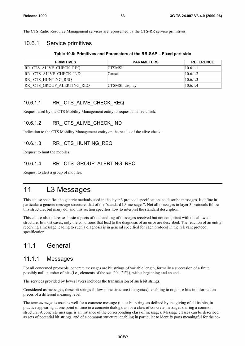
3GPP
3G TS 24.007 V3.4.0 (2000-06)83Release 1999
The CTS Radio Resource Management services are represented by the CTS-RR service primitives.
10.6.1 Service primitives
Table 10.6: Primitives and Parameters at the RR-SAP � Fixed part side
PRIMITIVES PARAMETERS REFERENCERR_CTS_ALIVE_CHECK_REQ CTSMSI 10.6.1.1RR_ CTS_ALIVE_CHECK_IND Cause 10.6.1.2RR_ CTS_HUNTING_REQ - 10.6.1.3RR_ CTS_GROUP_ALERTING_REQ CTSMSI, display 10.6.1.4
10.6.1.1 RR_ CTS_ALIVE_CHECK_REQ
Request used by the CTS Mobility Management entity to request an alive check.
10.6.1.2 RR_ CTS_ALIVE_CHECK_IND
Indication to the CTS Mobility Management entity on the results of the alive check.
10.6.1.3 RR_ CTS_HUNTING_REQ
Request to hunt the mobiles.
10.6.1.4 RR_ CTS_GROUP_ALERTING_REQ
Request to alert a group of mobiles.
11 L3 MessagesThis clause specifies the generic methods used in the layer 3 protocol specifications to describe messages. It define inparticular a generic message structure, that of the "standard L3 messages". Not all messages in layer 3 protocols followthis structure, but many do, and this section specifies how to interpret the standard description.
This clause also addresses basic aspects of the handling of messages received but not compliant with the allowedstructure. In most cases, only the conditions that lead to the diagnosis of an error are described. The reaction of an entityreceiving a message leading to such a diagnosis is in general specified for each protocol in the relevant protocolspecification.
11.1 General
11.1.1 MessagesFor all concerned protocols, concrete messages are bit strings of variable length, formally a succession of a finite,possibly null, number of bits (i.e., elements of the set {"0", "1"}), with a beginning and an end.
The services provided by lower layers includes the transmission of such bit strings.
Considered as messages, these bit strings follow some structure (the syntax), enabling to organise bits in informationpieces of a different meaning level.
The term message is used as well for a concrete message (i.e., a bit-string, as defined by the giving of all its bits, inpractice appearing at one point of time in a concrete dialog), as for a class of concrete messages sharing a commonstructure. A concrete message is an instance of the corresponding class of messages. Message classes can be describedas sets of potential bit strings, and of a common structure, enabling in particular to identify parts meaningful for the co-

3GPP
3G TS 24.007 V3.4.0 (2000-06)84Release 1999
operation functions the protocol supports.
In general, in the rest of the clause as in the protocol specifications, the term message will be used to refer to the class. Itmay be used, when the context prevents ambiguity, to refer to a message instance (e.g., a received is usually a messageinstance). In the rest of this clause, the term message instance will be used when needed to refer unambiguously tospecific concrete message, i.e., to a specific bit string.
A message (message class) can be described directly as a set of bit strings, using the formal notation described inAnnex B.
A message can also be described as a standard L3 message, in which case the interpretation of the message descriptionin term of a set of bit strings is specified in the next sub-clauses.
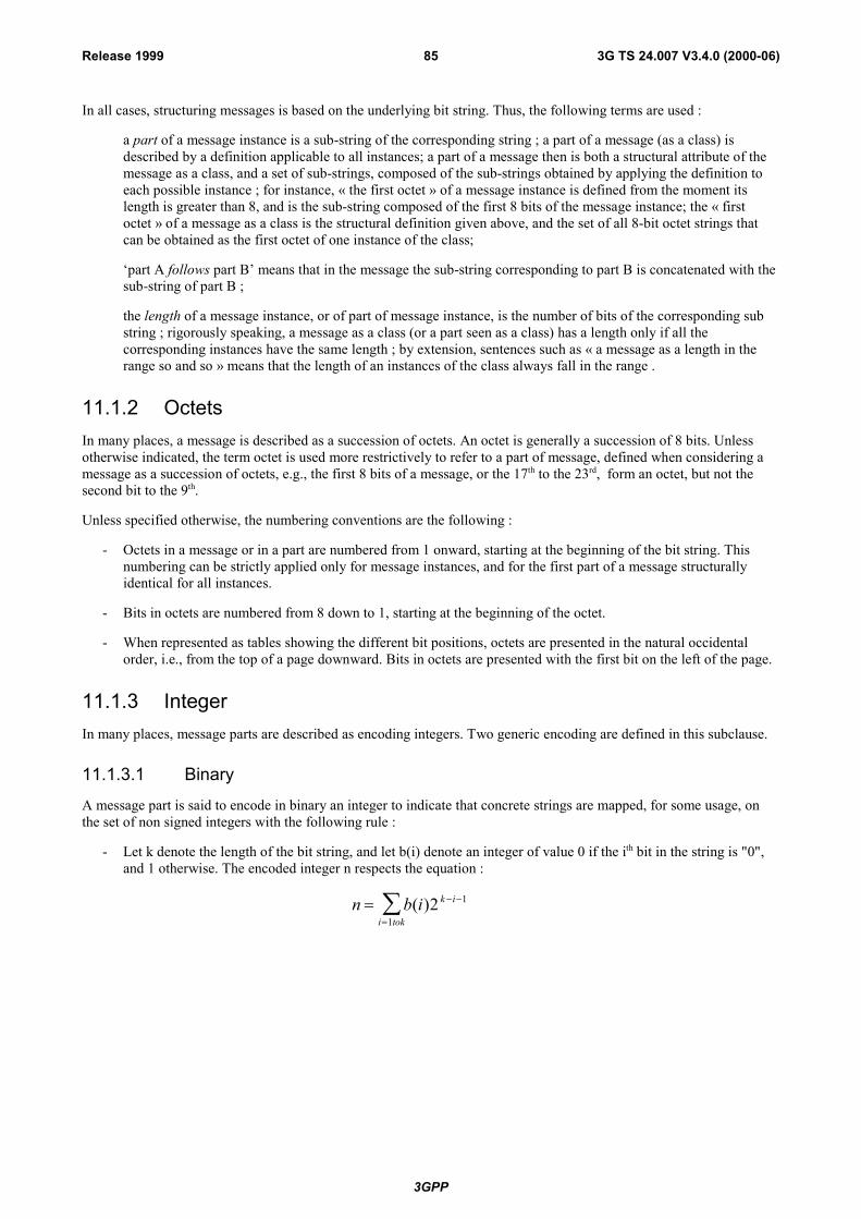
3GPP
3G TS 24.007 V3.4.0 (2000-06)85Release 1999
In all cases, structuring messages is based on the underlying bit string. Thus, the following terms are used :
a part of a message instance is a sub-string of the corresponding string ; a part of a message (as a class) isdescribed by a definition applicable to all instances; a part of a message then is both a structural attribute of themessage as a class, and a set of sub-strings, composed of the sub-strings obtained by applying the definition toeach possible instance ; for instance, « the first octet » of a message instance is defined from the moment itslength is greater than 8, and is the sub-string composed of the first 8 bits of the message instance; the « firstoctet » of a message as a class is the structural definition given above, and the set of all 8-bit octet strings thatcan be obtained as the first octet of one instance of the class;
�part A follows part B� means that in the message the sub-string corresponding to part B is concatenated with thesub-string of part B ;
the length of a message instance, or of part of message instance, is the number of bits of the corresponding substring ; rigorously speaking, a message as a class (or a part seen as a class) has a length only if all thecorresponding instances have the same length ; by extension, sentences such as « a message as a length in therange so and so » means that the length of an instances of the class always fall in the range .
11.1.2 OctetsIn many places, a message is described as a succession of octets. An octet is generally a succession of 8 bits. Unlessotherwise indicated, the term octet is used more restrictively to refer to a part of message, defined when considering amessage as a succession of octets, e.g., the first 8 bits of a message, or the 17th to the 23rd, form an octet, but not thesecond bit to the 9th.
Unless specified otherwise, the numbering conventions are the following :
- Octets in a message or in a part are numbered from 1 onward, starting at the beginning of the bit string. Thisnumbering can be strictly applied only for message instances, and for the first part of a message structurallyidentical for all instances.
- Bits in octets are numbered from 8 down to 1, starting at the beginning of the octet.
- When represented as tables showing the different bit positions, octets are presented in the natural occidentalorder, i.e., from the top of a page downward. Bits in octets are presented with the first bit on the left of the page.
11.1.3 IntegerIn many places, message parts are described as encoding integers. Two generic encoding are defined in this subclause.
11.1.3.1 Binary
A message part is said to encode in binary an integer to indicate that concrete strings are mapped, for some usage, onthe set of non signed integers with the following rule :
- Let k denote the length of the bit string, and let b(i) denote an integer of value 0 if the ith bit in the string is "0",and 1 otherwise. The encoded integer n respects the equation :
n b i k i
i tok= − −
=∑ ( )2 1
1
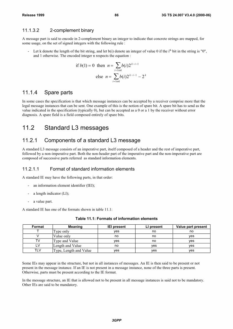
3GPP
3G TS 24.007 V3.4.0 (2000-06)86Release 1999
11.1.3.2 2-complement binary
A message part is said to encode in 2-complement binary an integer to indicate that concrete strings are mapped, forsome usage, on the set of signed integers with the following rule :
- Let k denote the length of the bit string, and let b(i) denote an integer of value 0 if the ith bit in the string is "0",and 1 otherwise. The encoded integer n respects the equation :
if then
else
b n b i
n b i
k i
i tok
k i
i tok
k
( ) ( )
( )
1 0 2
2 2
1
1
1
1
= =
= −
− −
=
− −
=
∑
∑
11.1.4 Spare partsIn some cases the specification is that which message instances can be accepted by a receiver comprise more that thelegal message instances that can be sent. One example of this is the notion of spare bit. A spare bit has to send as thevalue indicated in the specification (typically 0), but can be accepted as a 0 or a 1 by the receiver without errordiagnosis. A spare field is a field composed entirely of spare bits.
11.2 Standard L3 messages
11.2.1 Components of a standard L3 messageA standard L3 message consists of an imperative part, itself composed of a header and the rest of imperative part,followed by a non-imperative part. Both the non-header part of the imperative part and the non-imperative part arecomposed of successive parts referred as standard information elements.
11.2.1.1 Format of standard information elements
A standard IE may have the following parts, in that order:
- an information element identifier (IEI);
- a length indicator (LI);
- a value part.
A standard IE has one of the formats shown in table 11.1:
Table 11.1: Formats of information elements
Format Meaning IEI present LI present Value part presentT Type only yes no noV Value only no no yes
TV Type and Value yes no yesLV Length and Value no yes yes
TLV Type, Length and Value yes yes yes
Some IEs may appear in the structure, but not in all instances of messages. An IE is then said to be present or notpresent in the message instance. If an IE is not present in a message instance, none of the three parts is present.Otherwise, parts must be present according to the IE format.
In the message structure, an IE that is allowed not to be present in all message instances is said not to be mandatory.Other IEs are said to be mandatory.
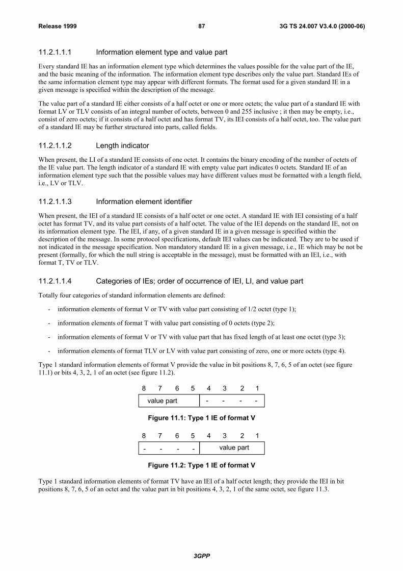
3GPP
3G TS 24.007 V3.4.0 (2000-06)87Release 1999
11.2.1.1.1 Information element type and value part
Every standard IE has an information element type which determines the values possible for the value part of the IE,and the basic meaning of the information. The information element type describes only the value part. Standard IEs ofthe same information element type may appear with different formats. The format used for a given standard IE in agiven message is specified within the description of the message.
The value part of a standard IE either consists of a half octet or one or more octets; the value part of a standard IE withformat LV or TLV consists of an integral number of octets, between 0 and 255 inclusive ; it then may be empty, i.e.,consist of zero octets; if it consists of a half octet and has format TV, its IEI consists of a half octet, too. The value partof a standard IE may be further structured into parts, called fields.
11.2.1.1.2 Length indicator
When present, the LI of a standard IE consists of one octet. It contains the binary encoding of the number of octets ofthe IE value part. The length indicator of a standard IE with empty value part indicates 0 octets. Standard IE of aninformation element type such that the possible values may have different values must be formatted with a length field,i.e., LV or TLV.
11.2.1.1.3 Information element identifier
When present, the IEI of a standard IE consists of a half octet or one octet. A standard IE with IEI consisting of a halfoctet has format TV, and its value part consists of a half octet. The value of the IEI depends on the standard IE, not onits information element type. The IEI, if any, of a given standard IE in a given message is specified within thedescription of the message. In some protocol specifications, default IEI values can be indicated. They are to be used ifnot indicated in the message specification. Non mandatory standard IE in a given message, i.e., IE which may be not bepresent (formally, for which the null string is acceptable in the message), must be formatted with an IEI, i.e., withformat T, TV or TLV.
11.2.1.1.4 Categories of IEs; order of occurrence of IEI, LI, and value part
Totally four categories of standard information elements are defined:
- information elements of format V or TV with value part consisting of 1/2 octet (type 1);
- information elements of format T with value part consisting of 0 octets (type 2);
- information elements of format V or TV with value part that has fixed length of at least one octet (type 3);
- information elements of format TLV or LV with value part consisting of zero, one or more octets (type 4).
Type 1 standard information elements of format V provide the value in bit positions 8, 7, 6, 5 of an octet (see figure11.1) or bits 4, 3, 2, 1 of an octet (see figure 11.2).
8 7 6 5 4 3 2 1
- - - -value part
Figure 11.1: Type 1 IE of format V
8 7 6 5 4 3 2 1
- - - - value part
Figure 11.2: Type 1 IE of format V
Type 1 standard information elements of format TV have an IEI of a half octet length; they provide the IEI in bitpositions 8, 7, 6, 5 of an octet and the value part in bit positions 4, 3, 2, 1 of the same octet, see figure 11.3.
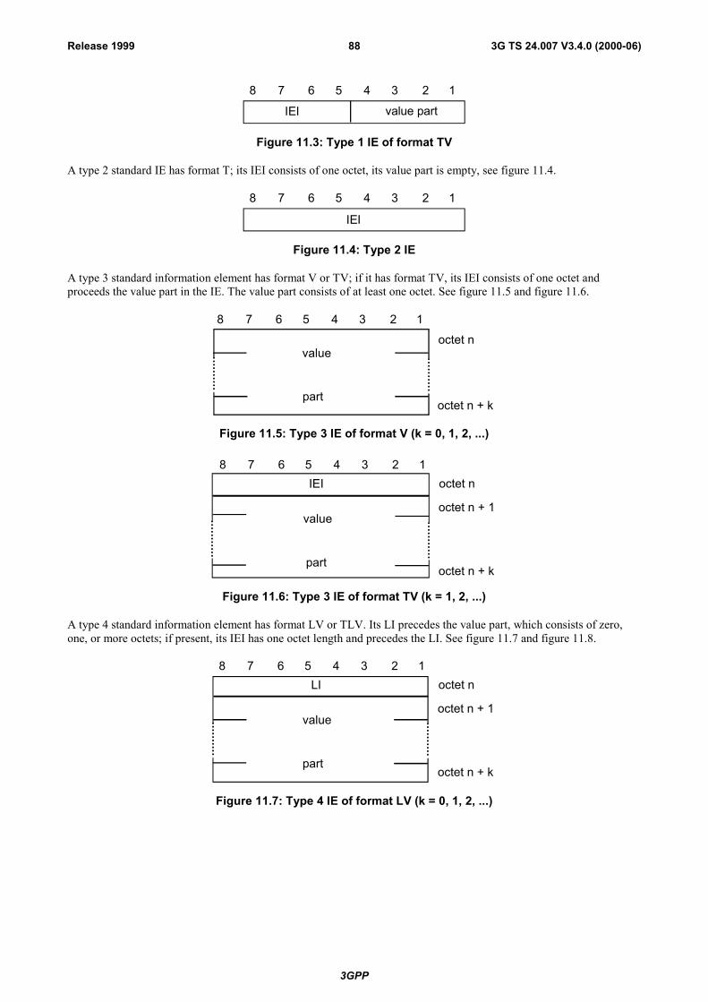
3GPP
3G TS 24.007 V3.4.0 (2000-06)88Release 1999
8 7 6 5 4 3 2 1
value partIEI
Figure 11.3: Type 1 IE of format TV
A type 2 standard IE has format T; its IEI consists of one octet, its value part is empty, see figure 11.4.
8 7 6 5 4 3 2 1
IEI
Figure 11.4: Type 2 IE
A type 3 standard information element has format V or TV; if it has format TV, its IEI consists of one octet andproceeds the value part in the IE. The value part consists of at least one octet. See figure 11.5 and figure 11.6.
8 7 6 5 4 3 2 1
value
part
octet n
octet n + k
Figure 11.5: Type 3 IE of format V (k = 0, 1, 2, ...)
value
part
octet n
octet n + k
8 7 6 5 4 3 2 1IEI
octet n + 1
Figure 11.6: Type 3 IE of format TV (k = 1, 2, ...)
A type 4 standard information element has format LV or TLV. Its LI precedes the value part, which consists of zero,one, or more octets; if present, its IEI has one octet length and precedes the LI. See figure 11.7 and figure 11.8.
value
part
octet n
octet n + k
8 7 6 5 4 3 2 1LI
octet n + 1
Figure 11.7: Type 4 IE of format LV (k = 0, 1, 2, ...)
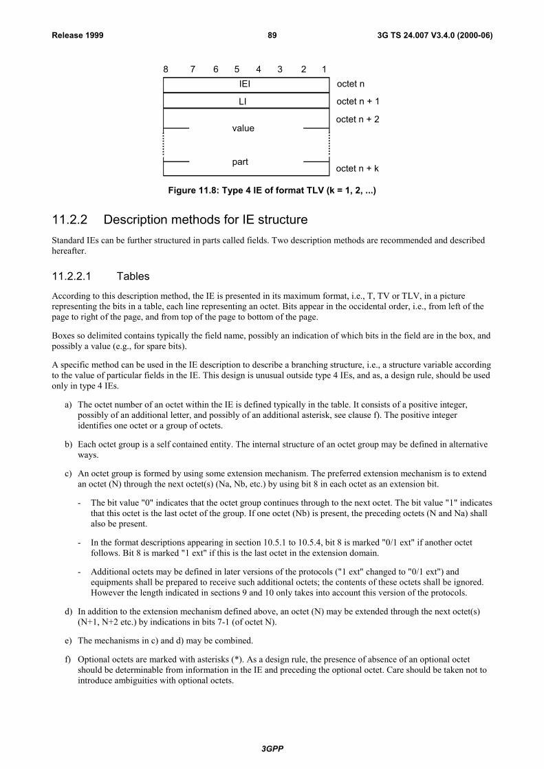
3GPP
3G TS 24.007 V3.4.0 (2000-06)89Release 1999
value
part
octet n + 1
octet n + k
LI
octet n + 2
octet n8 7 6 5 4 3 2 1
IEI
Figure 11.8: Type 4 IE of format TLV (k = 1, 2, ...)
11.2.2 Description methods for IE structureStandard IEs can be further structured in parts called fields. Two description methods are recommended and describedhereafter.
11.2.2.1 Tables
According to this description method, the IE is presented in its maximum format, i.e., T, TV or TLV, in a picturerepresenting the bits in a table, each line representing an octet. Bits appear in the occidental order, i.e., from left of thepage to right of the page, and from top of the page to bottom of the page.
Boxes so delimited contains typically the field name, possibly an indication of which bits in the field are in the box, andpossibly a value (e.g., for spare bits).
A specific method can be used in the IE description to describe a branching structure, i.e., a structure variable accordingto the value of particular fields in the IE. This design is unusual outside type 4 IEs, and as, a design rule, should be usedonly in type 4 IEs.
a) The octet number of an octet within the IE is defined typically in the table. It consists of a positive integer,possibly of an additional letter, and possibly of an additional asterisk, see clause f). The positive integeridentifies one octet or a group of octets.
b) Each octet group is a self contained entity. The internal structure of an octet group may be defined in alternativeways.
c) An octet group is formed by using some extension mechanism. The preferred extension mechanism is to extendan octet (N) through the next octet(s) (Na, Nb, etc.) by using bit 8 in each octet as an extension bit.
- The bit value "0" indicates that the octet group continues through to the next octet. The bit value "1" indicatesthat this octet is the last octet of the group. If one octet (Nb) is present, the preceding octets (N and Na) shallalso be present.
- In the format descriptions appearing in section 10.5.1 to 10.5.4, bit 8 is marked "0/1 ext" if another octetfollows. Bit 8 is marked "1 ext" if this is the last octet in the extension domain.
- Additional octets may be defined in later versions of the protocols ("1 ext" changed to "0/1 ext") andequipments shall be prepared to receive such additional octets; the contents of these octets shall be ignored.However the length indicated in sections 9 and 10 only takes into account this version of the protocols.
d) In addition to the extension mechanism defined above, an octet (N) may be extended through the next octet(s)(N+1, N+2 etc.) by indications in bits 7-1 (of octet N).
e) The mechanisms in c) and d) may be combined.
f) Optional octets are marked with asterisks (*). As a design rule, the presence of absence of an optional octetshould be determinable from information in the IE and preceding the optional octet. Care should be taken not tointroduce ambiguities with optional octets.
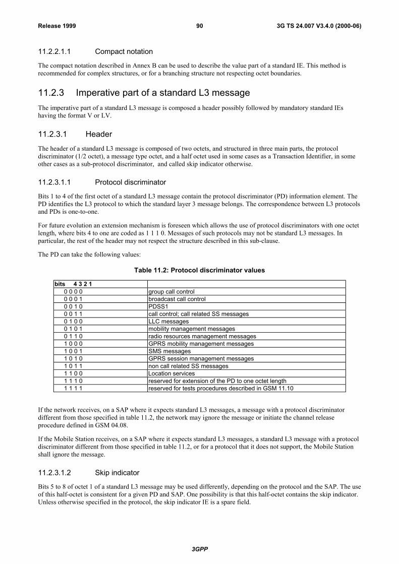
3GPP
3G TS 24.007 V3.4.0 (2000-06)90Release 1999
11.2.2.1.1 Compact notation
The compact notation described in Annex B can be used to describe the value part of a standard IE. This method isrecommended for complex structures, or for a branching structure not respecting octet boundaries.
11.2.3 Imperative part of a standard L3 messageThe imperative part of a standard L3 message is composed a header possibly followed by mandatory standard IEshaving the format V or LV.
11.2.3.1 Header
The header of a standard L3 message is composed of two octets, and structured in three main parts, the protocoldiscriminator (1/2 octet), a message type octet, and a half octet used in some cases as a Transaction Identifier, in someother cases as a sub-protocol discriminator, and called skip indicator otherwise.
11.2.3.1.1 Protocol discriminator
Bits 1 to 4 of the first octet of a standard L3 message contain the protocol discriminator (PD) information element. ThePD identifies the L3 protocol to which the standard layer 3 message belongs. The correspondence between L3 protocolsand PDs is one-to-one.
For future evolution an extension mechanism is foreseen which allows the use of protocol discriminators with one octetlength, where bits 4 to one are coded as 1 1 1 0. Messages of such protocols may not be standard L3 messages. Inparticular, the rest of the header may not respect the structure described in this sub-clause.
The PD can take the following values:
Table 11.2: Protocol discriminator values
bits 4 3 2 10 0 0 0 group call control0 0 0 1 broadcast call control0 0 1 0 PDSS10 0 1 1 call control; call related SS messages0 1 0 0 LLC messages0 1 0 1 mobility management messages0 1 1 0 radio resources management messages1 0 0 0 GPRS mobility management messages1 0 0 1 SMS messages1 0 1 0 GPRS session management messages1 0 1 1 non call related SS messages1 1 0 0 Location services1 1 1 0 reserved for extension of the PD to one octet length1 1 1 1 reserved for tests procedures described in GSM 11.10
If the network receives, on a SAP where it expects standard L3 messages, a message with a protocol discriminatordifferent from those specified in table 11.2, the network may ignore the message or initiate the channel releaseprocedure defined in GSM 04.08.
If the Mobile Station receives, on a SAP where it expects standard L3 messages, a standard L3 message with a protocoldiscriminator different from those specified in table 11.2, or for a protocol that it does not support, the Mobile Stationshall ignore the message.
11.2.3.1.2 Skip indicator
Bits 5 to 8 of octet 1 of a standard L3 message may be used differently, depending on the protocol and the SAP. The useof this half-octet is consistent for a given PD and SAP. One possibility is that this half-octet contains the skip indicator.Unless otherwise specified in the protocol, the skip indicator IE is a spare field.
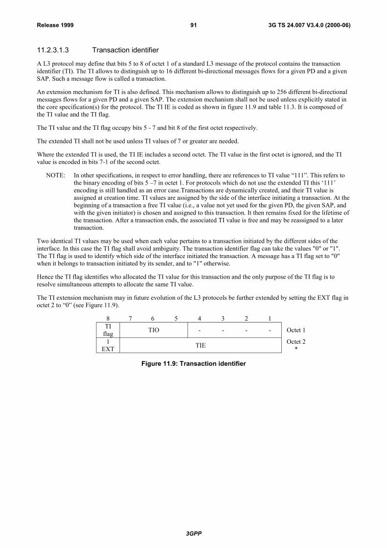
3GPP
3G TS 24.007 V3.4.0 (2000-06)91Release 1999
11.2.3.1.3 Transaction identifier
A L3 protocol may define that bits 5 to 8 of octet 1 of a standard L3 message of the protocol contains the transactionidentifier (TI). The TI allows to distinguish up to 16 different bi-directional messages flows for a given PD and a givenSAP. Such a message flow is called a transaction.
An extension mechanism for TI is also defined. This mechanism allows to distinguish up to 256 different bi-directionalmessages flows for a given PD and a given SAP. The extension mechanism shall not be used unless explicitly stated inthe core specification(s) for the protocol. The TI IE is coded as shown in figure 11.9 and table 11.3. It is composed ofthe TI value and the TI flag.
The TI value and the TI flag occupy bits 5 - 7 and bit 8 of the first octet respectively.
The extended TI shall not be used unless TI values of 7 or greater are needed.
Where the extended TI is used, the TI IE includes a second octet. The TI value in the first octet is ignored, and the TIvalue is encoded in bits 7-1 of the second octet.
NOTE: In other specifications, in respect to error handling, there are references to TI value �111�. This refers tothe binary encoding of bits 5 �7 in octet 1. For protocols which do not use the extended TI this �111�encoding is still handled as an error case.Transactions are dynamically created, and their TI value isassigned at creation time. TI values are assigned by the side of the interface initiating a transaction. At thebeginning of a transaction a free TI value (i.e., a value not yet used for the given PD, the given SAP, andwith the given initiator) is chosen and assigned to this transaction. It then remains fixed for the lifetime ofthe transaction. After a transaction ends, the associated TI value is free and may be reassigned to a latertransaction.
Two identical TI values may be used when each value pertains to a transaction initiated by the different sides of theinterface. In this case the TI flag shall avoid ambiguity. The transaction identifier flag can take the values "0" or "1".The TI flag is used to identify which side of the interface initiated the transaction. A message has a TI flag set to "0"when it belongs to transaction initiated by its sender, and to "1" otherwise.
Hence the TI flag identifies who allocated the TI value for this transaction and the only purpose of the TI flag is toresolve simultaneous attempts to allocate the same TI value.
The TI extension mechanism may in future evolution of the L3 protocols be further extended by setting the EXT flag inoctet 2 to �0� (see Figure 11.9).
8 7 6 5 4 3 2 1TI
flag TIO - - - - Octet 1
1EXT TIE Octet 2
*
Figure 11.9: Transaction identifier
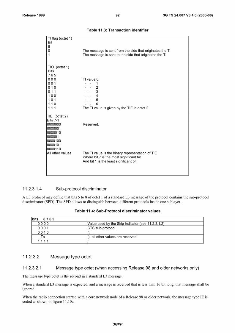
3GPP
3G TS 24.007 V3.4.0 (2000-06)92Release 1999
Table 11.3: Transaction identifier
TI flag (octet 1) Bit 8 0 The message is sent from the side that originates the TI 1 The message is sent to the side that originates the TI
TIO (octet 1) Bits 7 6 5 0 0 0 TI value 0 0 0 1 - - 1 0 1 0 - - 2 0 1 1 - - 3 1 0 0 - - 4 1 0 1 - - 5 1 1 0 - - 6 1 1 1 The TI value is given by the TIE in octet 2
TIE (octet 2)Bits 7-10000000000000100000100000011000010000001010000110
Reserved.
All other values The TI value is the binary representation of TIEWhere bit 7 is the most significant bitAnd bit 1 is the least significant bit
11.2.3.1.4 Sub-protocol discriminator
A L3 protocol may define that bits 5 to 8 of octet 1 of a standard L3 message of the protocol contains the sub-protocoldiscriminator (SPD). The SPD allows to distinguish between different protocols inside one sublayer.
Table 11.4: Sub-Protocol discriminator values
bits 8 7 6 50 0 0 0 Value used by the Skip Indicator (see 11.2.3.1.2)0 0 0 1 CTS sub-protocol0 0 1 0 \ To } all other values are reserved1 1 1 1 /
11.2.3.2 Message type octet
11.2.3.2.1 Message type octet (when accessing Release 98 and older networks only)
The message type octet is the second in a standard L3 message.
When a standard L3 message is expected, and a message is received that is less than 16 bit long, that message shall beignored.
When the radio connection started with a core network node of a Release 98 or older network, the message type IE iscoded as shown in figure 11.10a.
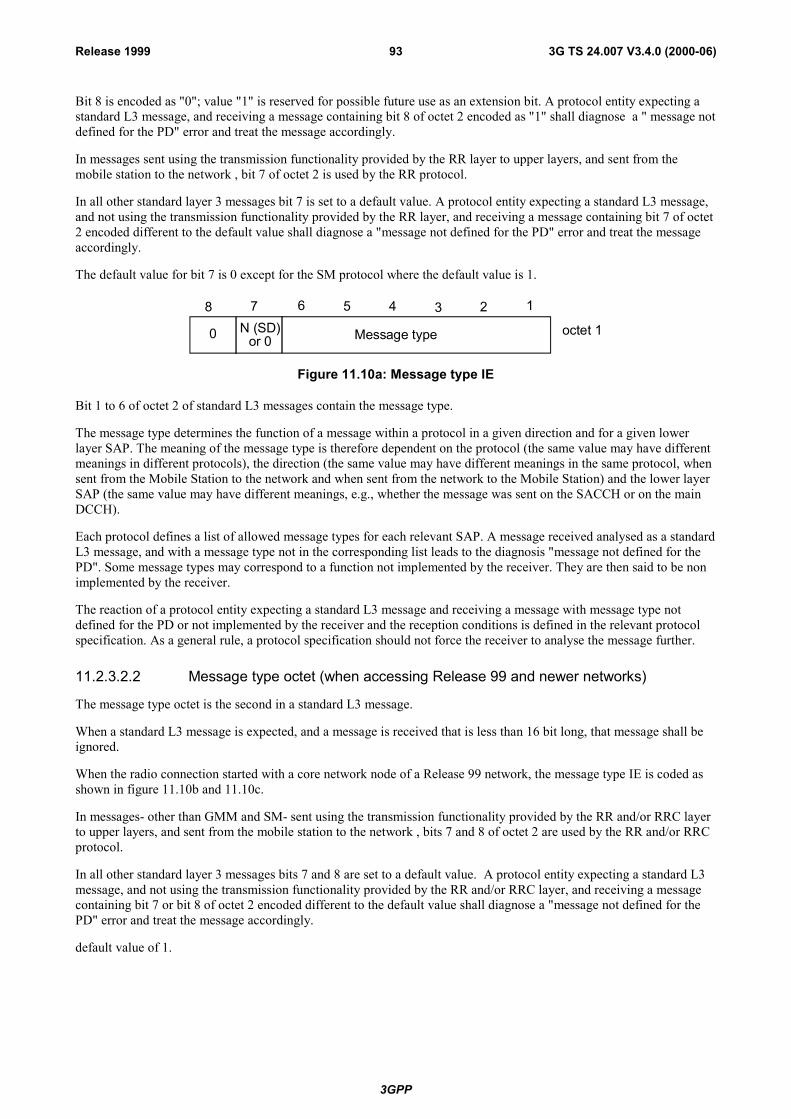
3GPP
3G TS 24.007 V3.4.0 (2000-06)93Release 1999
Bit 8 is encoded as "0"; value "1" is reserved for possible future use as an extension bit. A protocol entity expecting astandard L3 message, and receiving a message containing bit 8 of octet 2 encoded as "1" shall diagnose a " message notdefined for the PD" error and treat the message accordingly.
In messages sent using the transmission functionality provided by the RR layer to upper layers, and sent from themobile station to the network , bit 7 of octet 2 is used by the RR protocol.
In all other standard layer 3 messages bit 7 is set to a default value. A protocol entity expecting a standard L3 message,and not using the transmission functionality provided by the RR layer, and receiving a message containing bit 7 of octet2 encoded different to the default value shall diagnose a "message not defined for the PD" error and treat the messageaccordingly.
The default value for bit 7 is 0 except for the SM protocol where the default value is 1.
8 7 6 5 4 3 2 1
0 octet 1Message typeN (SD)or 0
Figure 11.10a: Message type IE
Bit 1 to 6 of octet 2 of standard L3 messages contain the message type.
The message type determines the function of a message within a protocol in a given direction and for a given lowerlayer SAP. The meaning of the message type is therefore dependent on the protocol (the same value may have differentmeanings in different protocols), the direction (the same value may have different meanings in the same protocol, whensent from the Mobile Station to the network and when sent from the network to the Mobile Station) and the lower layerSAP (the same value may have different meanings, e.g., whether the message was sent on the SACCH or on the mainDCCH).
Each protocol defines a list of allowed message types for each relevant SAP. A message received analysed as a standardL3 message, and with a message type not in the corresponding list leads to the diagnosis "message not defined for thePD". Some message types may correspond to a function not implemented by the receiver. They are then said to be nonimplemented by the receiver.
The reaction of a protocol entity expecting a standard L3 message and receiving a message with message type notdefined for the PD or not implemented by the receiver and the reception conditions is defined in the relevant protocolspecification. As a general rule, a protocol specification should not force the receiver to analyse the message further.
11.2.3.2.2 Message type octet (when accessing Release 99 and newer networks)
The message type octet is the second in a standard L3 message.
When a standard L3 message is expected, and a message is received that is less than 16 bit long, that message shall beignored.
When the radio connection started with a core network node of a Release 99 network, the message type IE is coded asshown in figure 11.10b and 11.10c.
In messages- other than GMM and SM- sent using the transmission functionality provided by the RR and/or RRC layerto upper layers, and sent from the mobile station to the network , bits 7 and 8 of octet 2 are used by the RR and/or RRCprotocol.
In all other standard layer 3 messages bits 7 and 8 are set to a default value. A protocol entity expecting a standard L3message, and not using the transmission functionality provided by the RR and/or RRC layer, and receiving a messagecontaining bit 7 or bit 8 of octet 2 encoded different to the default value shall diagnose a "message not defined for thePD" error and treat the message accordingly.
default value of 1.
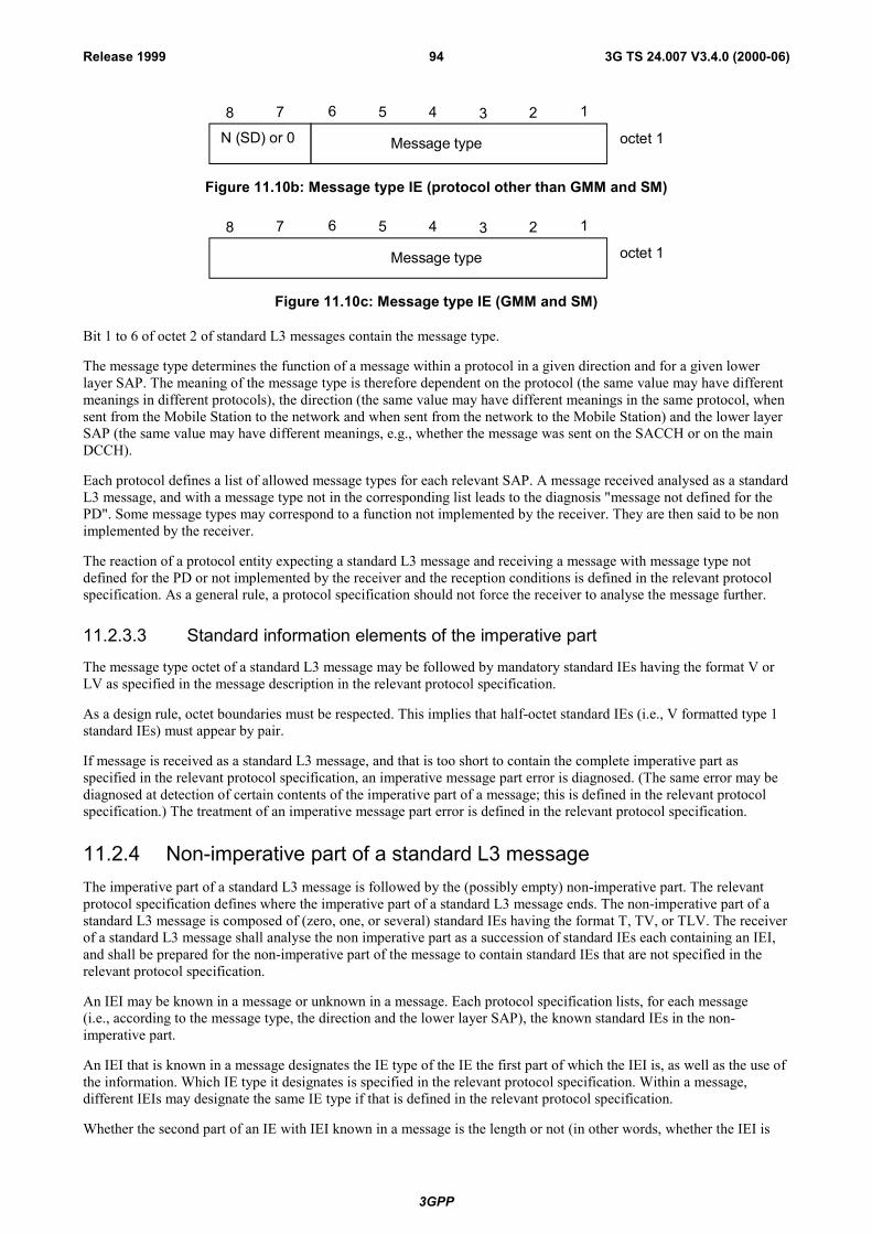
3GPP
3G TS 24.007 V3.4.0 (2000-06)94Release 1999
8 7 6 5 4 3 2 1
octet 1Message typeN (SD) or 0
Figure 11.10b: Message type IE (protocol other than GMM and SM)
8 7 6 5 4 3 2 1
octet 1Message type
Figure 11.10c: Message type IE (GMM and SM)
Bit 1 to 6 of octet 2 of standard L3 messages contain the message type.
The message type determines the function of a message within a protocol in a given direction and for a given lowerlayer SAP. The meaning of the message type is therefore dependent on the protocol (the same value may have differentmeanings in different protocols), the direction (the same value may have different meanings in the same protocol, whensent from the Mobile Station to the network and when sent from the network to the Mobile Station) and the lower layerSAP (the same value may have different meanings, e.g., whether the message was sent on the SACCH or on the mainDCCH).
Each protocol defines a list of allowed message types for each relevant SAP. A message received analysed as a standardL3 message, and with a message type not in the corresponding list leads to the diagnosis "message not defined for thePD". Some message types may correspond to a function not implemented by the receiver. They are then said to be nonimplemented by the receiver.
The reaction of a protocol entity expecting a standard L3 message and receiving a message with message type notdefined for the PD or not implemented by the receiver and the reception conditions is defined in the relevant protocolspecification. As a general rule, a protocol specification should not force the receiver to analyse the message further.
11.2.3.3 Standard information elements of the imperative part
The message type octet of a standard L3 message may be followed by mandatory standard IEs having the format V orLV as specified in the message description in the relevant protocol specification.
As a design rule, octet boundaries must be respected. This implies that half-octet standard IEs (i.e., V formatted type 1standard IEs) must appear by pair.
If message is received as a standard L3 message, and that is too short to contain the complete imperative part asspecified in the relevant protocol specification, an imperative message part error is diagnosed. (The same error may bediagnosed at detection of certain contents of the imperative part of a message; this is defined in the relevant protocolspecification.) The treatment of an imperative message part error is defined in the relevant protocol specification.
11.2.4 Non-imperative part of a standard L3 messageThe imperative part of a standard L3 message is followed by the (possibly empty) non-imperative part. The relevantprotocol specification defines where the imperative part of a standard L3 message ends. The non-imperative part of astandard L3 message is composed of (zero, one, or several) standard IEs having the format T, TV, or TLV. The receiverof a standard L3 message shall analyse the non imperative part as a succession of standard IEs each containing an IEI,and shall be prepared for the non-imperative part of the message to contain standard IEs that are not specified in therelevant protocol specification.
An IEI may be known in a message or unknown in a message. Each protocol specification lists, for each message(i.e., according to the message type, the direction and the lower layer SAP), the known standard IEs in the non-imperative part.
An IEI that is known in a message designates the IE type of the IE the first part of which the IEI is, as well as the use ofthe information. Which IE type it designates is specified in the relevant protocol specification. Within a message,different IEIs may designate the same IE type if that is defined in the relevant protocol specification.
Whether the second part of an IE with IEI known in a message is the length or not (in other words, whether the IEI is
3GPP
3G TS 24.007 V3.4.0 (2000-06)95Release 1999
the first part of an IE formatted as TLV or not) is specified in the relevant protocol specification.
Unless otherwise specified in the protocol specification, the receiver shall assume that IE with unknown IEI are TVformatted type 1, T formatted type 2 or TLV formatted type 4 standard IEs. The IEI of unknown IEs together with,when applicable, the length indicator, enable the receiver to determine the total length of the IE, and then to skipunknown IEs. The receiver shall assume the following rule for IEs with unknown IEI :
Bit 8 of the IEI octet is set to "1" indicates a TV formatted type 1 standard IE or a T formatted type 2 IEs, and to"0" indicates a TLV formatted type 4 IE. Hence, a 1 valued bit 8 indicates that the whole IE is one octet long,and a 0 valued bit 8 indicates that the following octet is a length octet.
As a design rule, it is recommended that IEIs of any TV formatted type 1, T formatted type 2 or TLV formatted type 4IE follow the rule, even if assumed to be known by all potential receivers.
A message may contain two or more IEs with equal IEI. Two IEs with the same IEI in a same message must have thesame format, and, when of type 3, the same length. More generally, care should be taken not to introduce ambiguitiesby using an IEI for two purposes. Ambiguities appear in particular when two IEs potentially immediately successivehave the same IEI but different meanings and when both are non-mandatory. As a recommended design rule, messagesshould contain a single IE of a given IEI.
Each protocol specification may put specific rules for the order of IEs in the non-imperative part. An IE known in themessage, but at a position non compliant with these rules is said to be out of sequence. An out of sequence IE isdecoded according to the format, and, when of type 3 the length, as defined in the message for its IEI.
11.2.5 Presence requirements of information elementsThe relevant protocol specification may define three different presence requirements (M, C, or O) for a standard IEwithin a given standard L3 message:
- M ("Mandatory") means that the IE shall be included by the sending side, and that the receiver diagnoses a"missing mandatory IE" error when detecting that the IE is not present. An IE belonging to the imperative part ofa message has presence requirement M. An IE belonging to the non-imperative part of a message may havepresence requirement M;
- C ("Conditional") means:
* that inclusion of the IE by the sender depends on conditions specified in the relevant protocol specification;
* that there are conditions for the receiver to expect that the IE is present and/or conditions for the receiver toexpect that the IE is not present in a received message of a given PD, SAP and message type; theseconditions depend only on the content of the message itself, and not for instance on the state in which themessage was received, or on the receiver characteristics; they are known as static conditions;
* that the receiver detecting that the IE is not present when sufficient static conditions are fulfilled for itspresence, shall diagnose a "missing conditional IE" error;
* that the receiver detecting that the IE is present when sufficient static conditions are fulfilled for its non-presence, shall diagnose an "unexpected conditional IE" error.
Only IEs belonging to the non-imperative part of a message may have presence requirement C;
- O ("Optional") means that the receiver shall never diagnose a "missing mandatory IE" error, a "missingconditional IE" error, or an "unexpected conditional IE" error because it detects that the IE is present or that theIE is not present. (There may however be conditions depending on the states, resources, etc. of the receiver todiagnose other errors.) Only IEs belonging to the non-imperative part of a message may have presencerequirement O.
Unless otherwise specified the presence of a IE of unknown IEI or of an out of sequence IE shall not lead by itself to anerror. An alternative specification is the �comprehension required� scheme. An IE is encoded as �comprehensionrequired� if bits 5, 6, 7 and 8 of its IEI are set to zero. The comprehension required scheme is to be applied if explicitlyindicated in the protocol specification. The reaction on the reception of an unknown or out of sequence IE coded as�comprehension required� is specified in the relevant protocol specification.
3GPP
3G TS 24.007 V3.4.0 (2000-06)96Release 1999
11.2.6 Description of standard L3 messagesThis subclause describes a generic description method for standard L3 messages, the tabular description. Protocolspecification may follow other methods.
A standard L3 message is described by a table listing the header elements and the standard IEs in the message. For eachelement is given:
- if applicable the IEI, in hexadecimal representation (one digit followed by and hyphen for TV formatted type 1,and two digits for the other cases);
- the name of the IE (this is used in particular for the description of conditional presence rules);
- the type of the information element, with a reference of where the internal structure of the value part is specified;
- the format of the standard IE (T, V, TV, LV or TLV); and
- the length, or the range of lengths, of the whole standard IE, including when applicable the T and L parts.
The list of elements is given in the table in the order they appear in the resulting bit string, with the exception ofhalf-octet elements in the imperative part : half octets in a pair are inverted. This applies in particular for the two firstheader elements : the protocol discriminator appears first in a table describing a standard L3 message.
11.3 Non standard L3 messagesIn some protocols, the structure of part or all of the messages might not always follow the standard L3 messagestructure. As a design rule, this should be consistent for a given protocol, direction and lower layer SAP.
A possibility is to describe the message with the compact notation described in Annex B.
A few consistent structures are found in the present protocol specifications, and are described hereafter.
Other structures can be described directly in the protocol specifications.
11.3.1 Case A : BCCH and AGCH/PCH messagesIn these cases, the SAP capability is for fixed length messages. The messages are structured as standard L3 messagesplus one octet in front, the L2 pseudo length octet, and a rest octet part at the end.
11.3.1.1 L2 Pseudo Length octet
This octet, the L2 pseudo length indicator octet, indicates the length in octets of the subsequent octet string that can beanalysed as a standard L3 message.
The octet is structured as follows:
Bits 3 to 8 encodes in binary the L2 pseudo length, i.e., the length of the part to be analysed as a standard L3message ;
Bit 2 is set to "0" ;
Bit 1 is set to "1".
A receiver expecting a message so structured and receiving a message with bit 1 of octet 1 (i.e., the 8th bit of themessage) set to "1" and bit 2 of octet 1 (i.e., the 7th bit of the message) different from "0", shall abandon the analysis ofthe message.
A receiver expecting a message so structured and receiving a message with an L2 pseudo length indicator encoding 0 or1 shall skip the indicated number of octets and not try to analyse the standard L3 message part.
A receiver expecting a message so structured and receiving a L2 pseudo length indicator bigger than what is compatiblewith the SAP capability shall abandon the analysis of the message.
3GPP
3G TS 24.007 V3.4.0 (2000-06)97Release 1999
11.3.1.2 Rest Octets
The part after the part structured as a standard L3 message, and up to the end of the message as constrained by lowerlayers, is presented as a non standard IE of variable length (sometime indicated as of type 5), the �rest octets� IE.
The rest octets element may be described by table description, or, preferably, using the compact notation described inAnnex B of this document.
11.3.1.3 Description of a modified standard L3 message
The description can be provided in the same way as a standard L3 message, with in the case of a tabular description onenon standard IE at the beginning (of type L2 pseudo length), and one non standard IE at the end.
11.3.2 Case B : SACCH messages sent in unacknowledged modeThe messages are structured either as standard L3 messages, or in the so-called short header format. The value of the 8th
bit (bit 1 of octet 1) of the link layer PDU distinguishes the two cases. In the case of the short header, the L3 message isthe same bit string as the link layer PDU, and has a fixed length. The following description includes the 2-bit link layerheader.
11.3.2.1 The first octet
Bits 1 and 2 are the link layer header. Bit 2 of octet 1 is set to "0", and bit 1 is reserved for the link layer.
A protocol discriminator is the first part of the message (starting bit 8 of octet 1). The protocol discriminator field mayhave different lengths. The following protocol discriminator is defined:
- 0 RR.
All additional PD defined for this structure shall start by 1. The reception of a message with bit 8 of octet 1 set to 1when expecting a message structured as defined by this clause shall be diagnosed as an unknown PD, and the messageignored.
As a design rule, a message type field should follow the PD, and of a length such that the PD and the message type fit inthe 6 first bits of the message.
11.3.2.2 The rest of the message
The rest of the structure is not more constrained.
The preferred description method is the one described in Annex B.
11.3.3 Design guidelines for non standard partsThe guidelines in this subclause apply to non standard parts, such as rest octets, short header broadcast message or fullynon standard L3 messages.
11.3.3.1 General
The structure should be as far as possible be such that the analysis can be conducted from beginning to end. In otherterms, the conditions determining the syntactic analysis of a part (e.g., tags, lengths) should appear before that part.
The part should be structured as a succession of information elements, each carrying an elementary semanticinformation. An information element should be composed of (possibly) a tag, than (possibly) a length indicator, then avalue part.
Tags can be of fixed or variable length, their extent being analysable from beginning to end. A typical tagging is the onebit tagging, which should preferably used as follows : value "0" indicates that the IE is no more than the tag bit, and "1"indicates that the IE continues at least with the next bit.
Variable length tagging should be used to distinguish between several possible formats of the element. Tag lengths arethen chosen according to packing efficiency criteria.

3GPP
3G TS 24.007 V3.4.0 (2000-06)98Release 1999
The T field of standard IEs can be presented as a variable tagging with only two lengths : 4 and 8 bits.
The length indicator can be of fixed or variable length, their extent being analysable from beginning to end. It shouldpreferably be presented as encoding the length in bits of the value part.
The L field of standard IEs can be presented as a fixed length (one octet) length indicator which can encode onlylengths multiple of 8 bits.
The value part can be described as further structured, in a similar way. This can be used to help the reading, and tocover some presence dependence.
11.4 Handling of superfluous informationAll equipment should be able to ignore any extra information present in an L3 message, which is not required for theproper operation of that equipment. For example, a mobile station may ignore the calling party BCD number if thatnumber is of no interest to the Mobile Station when a SETUP message is received.
11.4.1 Information elements that are unnecessary in a messageThe relevant protocol specification may define certain IEs to be under some conditions unnecessary in a L3 message. Aprotocol entity detecting an unnecessary IE in a received L3 message shall ignore the contents of that IE for treating themessage; it is not obliged to check whether the contents of the IE are syntactically correct.
11.4.2 Other syntactic errorsThis section applies to the analysis of the value part of an information element. It defines the following terminology:
- An IE is defined to be syntactically incorrect in a message if it contains at least one value defined as "reserved",or if its value part violates syntactic rules given in the specification of the value part. However it is not asyntactical error that a type 4 standard IE specifies in its length indicator a greater length than possible accordingto the value part specification : extra bits are ignored.
- A message is defined to have semantically incorrect contents if it contains information which, possiblydependant on the state of the receiver, is in contradiction to the resources of the receiver and/or to the proceduralpart.
3GPP
3G T
S 24
.007
V3.
4.0
(200
0-06
)99
Rel
ease
199
9
Anne
x A
(info
rmat
ive)
:M
N-S
ervi
ces
arro
w d
iagr
am

3GPP
3G T
S 24
.007
V3.
4.0
(200
0-06
)10
0R
elea
se 1
999 C
C
MM
RR
L2
L2
R
R
MM
CC
Mob
ile S
tatio
nN
etw
ork
MN
CC
-SET
UP-
REQ
DL-
RAN
DO
M-A
CC
-REQ
/IND
(CH
ANN
REQ
)
DL-
UN
IT-D
ATA-
IND
/REQ
(IMM
ASS
)
DL-
ASS-
REQ
DL-
EST-
IND
DL-
EST-
CN
FU
A (C
M S
ERV
REQ
)
AUTH
REQ
AUTH
RES
CIP
H M
OD
E C
MD
CIP
H M
OD
E C
OM
SETU
P
CAL
L PR
OC
ASSI
GN
CM
D
ASSI
GN
CO
M
ALER
T
CO
NN
ECT
CO
NN
AC
K
MN
CC
-CAL
L-PR
OC
-IND
MN
CC
-ALE
RT-
IND
MN
CC
-SET
UP-
CN
F
MM
CC
-EST
-CN
F
MM
CC
-SYN
C-IN
D
(res
ass
)
RR
-EST
-CN
F
RR
-SYN
K-IN
D
(res
ass
)
RR
-EST
-IND
(CM
SER
V R
EQ)
RR
-SYN
C-R
EQ
(ci
ph)
RR
-SYN
C-C
NF
(c
iph)
RR
-SYN
C-R
EQ
(re
s as
s)
RR
-SYN
C-C
NF
(res
ass)
MM
CC
-EST
-IND
(SET
UP)
MM
CC
-SYN
C-R
EQ
(re
s as
s)
MM
CC
-SYN
C-C
NF
(
res
ass)
MN
CC
-SET
UP-
IND
MN
CC
-CAL
L-PR
OC
-REQ
MN
CC
-ALE
RT-
REQ
MN
CC
-SET
UP-
RSP
MN
CC
-SET
UP-
CO
MPL
-IND
DAT
A FL
OW
MM
CC
-EST
-REQ
RR
-EST
-REQ
(CM
SER
V R
EQ)
RR
-SYN
C-IN
D
(ci
ph)
SABM
(CM
SER
V R
EQ)
Fig
ure
A.1:
Mob
ile o
rigin
ated
Cal
l Set
up. S
ucce
ssfu
l cas
e
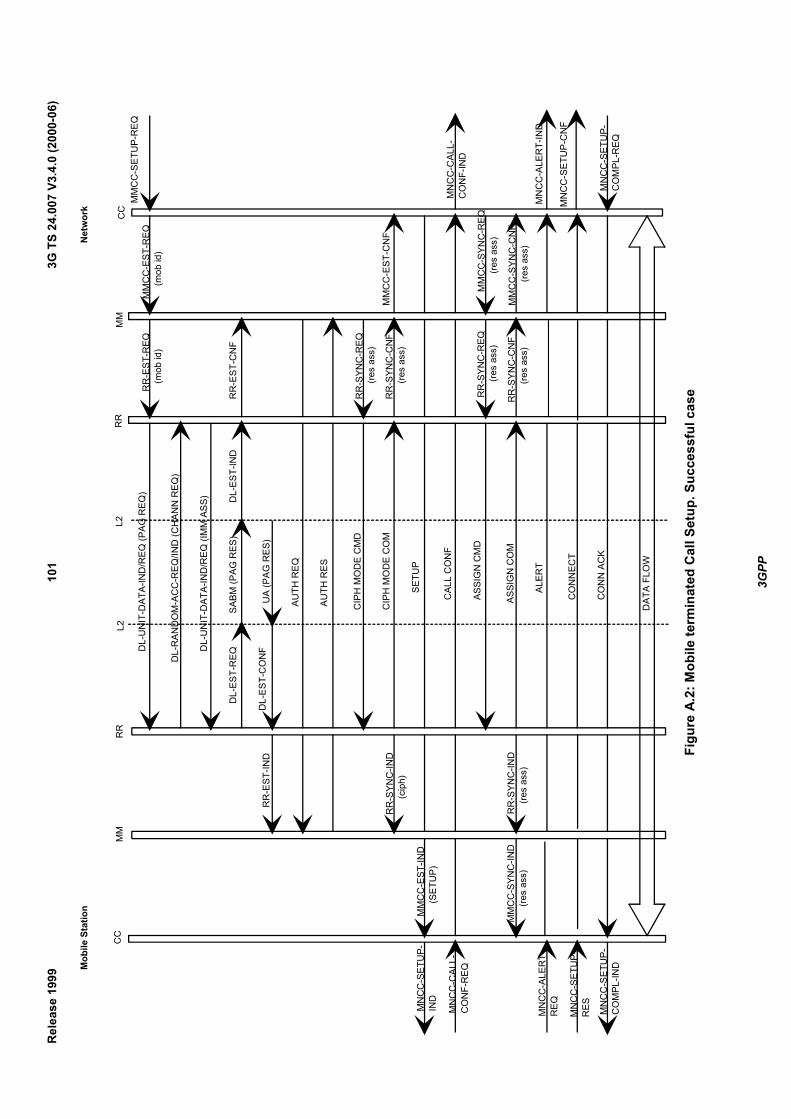
3GPP
3G T
S 24
.007
V3.
4.0
(200
0-06
)10
1R
elea
se 1
999 M
obile
Sta
tion
Net
wor
k
DAT
A FL
OW
DL-
RAN
DO
M-A
CC
-REQ
/IND
(CH
ANN
REQ
)
DL-
UN
IT-D
ATA-
IND
/REQ
(IM
M A
SS)
DL-
EST-
REQ
DL-
EST-
IND
DL-
EST-
CO
NF
UA
(PAG
RES
)
AUTH
REQ
AUTH
RES
CIP
H M
OD
E C
MD
CIP
H M
OD
E C
OM
SETU
P
CAL
L C
ON
F
ASSI
GN
CM
D
ASSI
GN
CO
M
ALER
T
CO
NN
ECT
CO
NN
AC
K
RR
-EST
-IND
RR
-SYN
C-IN
D
(c
iph)
RR
-SYN
C-IN
D
(res
ass
)
MM
CC
-EST
-IND
(
SETU
P)
MM
CC
-SYN
C-IN
D
(re
s as
s)
MN
CC
-SET
UP-
IND
MN
CC
-CAL
L-C
ON
F-R
EQ
MN
CC
-ALE
RT-
REQ
MN
CC
-SET
UP-
RES MN
CC
-SET
UP-
CO
MPL
-IND
RR
-EST
-REQ
(m
ob id
)
RR
-EST
-CN
F
RR
-SYN
C-R
EQ
(re
s as
s)
RR
-SYN
C-C
NF
(res
ass)
RR
-SYN
C-R
EQ
(re
s as
s)
RR
-SYN
C-C
NF
(res
ass
)
MM
CC
-EST
-REQ
(
mob
id)
MM
CC
-SET
UP-
REQ
MM
CC
-EST
-CN
F
MN
CC
-CAL
L-C
ON
F-IN
D
MM
CC
-SYN
C-R
EQ
(r
es a
ss)
MM
CC
-SYN
C-C
NF
(re
s as
s)M
NC
C-A
LER
T-IN
D
MN
CC
-SET
UP-
CN
F
MN
CC
-SET
UP-
CO
MPL
-REQ
SABM
(PAG
RES
)
DL-
UN
IT-D
ATA-
IND
/REQ
(PAG
REQ
)
MM
CC
RR
L2L2
RR
MM
CC
Figu
re A
.2: M
obile
term
inat
ed C
all S
etup
. Suc
cess
ful c
ase
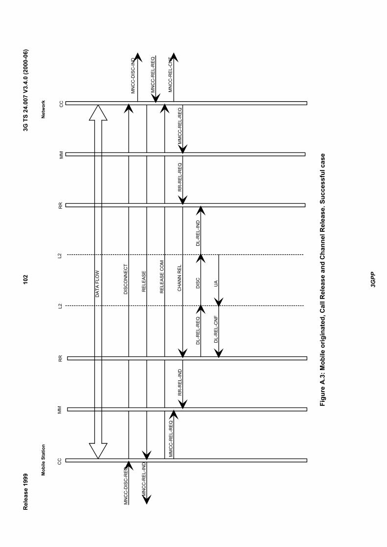
3GPP
3G T
S 24
.007
V3.
4.0
(200
0-06
)10
2R
elea
se 1
999 M
obile
Sta
tion
Net
wor
k
DAT
A FL
OW
MN
CC
-DIS
C-R
EQ
MN
CC
-REL
-IND
MM
CC
-REL
-REQ
RR
-REL
-IND
DIS
CO
NN
ECT
REL
EASE
REL
EASE
CO
M
CH
ANN
REL
DL-
REL
-REQ
DL-
REL
-CN
F
DIS
C
UA
DL-
REL
-IND
RR
-REL
-REQ
MM
CC
-REL
-REQ
MN
CC
-DIS
C-IN
D
MN
CC
-REL
-REQ
MN
CC
-REL
-CN
F
CC
RR
L2C
CM
MM
MR
RL2
Figu
re A
.3: M
obile
orig
inat
ed, C
all R
elea
se a
nd C
hann
el R
elea
se. S
ucce
ssfu
l cas
e
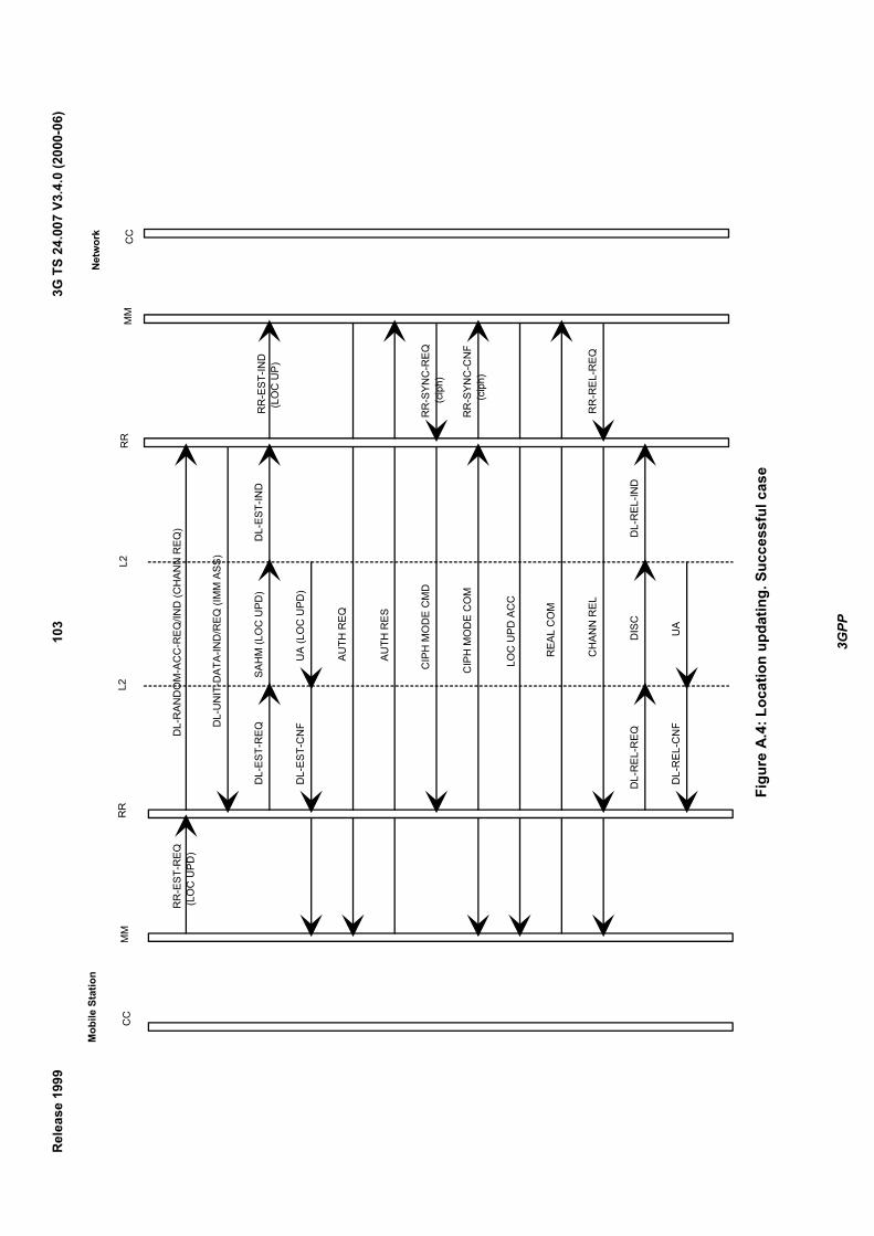
3GPP
3G T
S 24
.007
V3.
4.0
(200
0-06
)10
3R
elea
se 1
999
Mob
ile S
tatio
nN
etw
ork
RR
-EST
-REQ
(LO
C U
PD)
DL-
RAN
DO
M-A
CC
-REQ
/IND
(CH
ANN
REQ
)
DL-
UN
IT-D
ATA-
IND
/REQ
(IM
M A
SS)
DL-
EST-
REQ
SAH
M (L
OC
UPD
)D
L-ES
T-IN
D
DL-
EST-
CN
FU
A (L
OC
UPD
)
AUTH
REQ
AUTH
RES
CIP
H M
OD
E C
MD
CIP
H M
OD
E C
OM
LOC
UPD
AC
C
REA
L C
OM
CH
ANN
REL
DIS
C
UA
DL-
REL
-REQ
DL-
REL
-CN
F
DL-
REL
-IND
RR
-EST
-IND
(LO
C U
P)
RR
-SYN
C-R
EQ
(ci
ph)
RR
-SYN
C-C
NF
(cip
h)
RR
-REL
-REQ
CC
MM
RR
L2C
CM
MR
RL2
Figu
re A
.4: L
ocat
ion
upda
ting.
Suc
cess
ful c
ase

3GPP
3G T
S 24
.007
V3.
4.0
(200
0-06
)10
4R
elea
se 1
999
Mob
ile S
tatio
nN
etw
ork
DAT
A FL
OW
DAT
A FL
OW
HAN
DO
CM
D
DL-
SUS-
REQ
(loc
al)
DL-
REL
-CN
F (lo
cal)
PHYS
INFO
DL-
RES
-REQ
DL-
EST-
CN
F
SAH
M
UA
HAN
DO
CO
M
DL-
EST-
IND
BS1
BS2
CC
MM
RR
L2C
CM
MR
RL2
Figu
re A
.5: H
ando
ver.
Succ
essf
ul c
ase
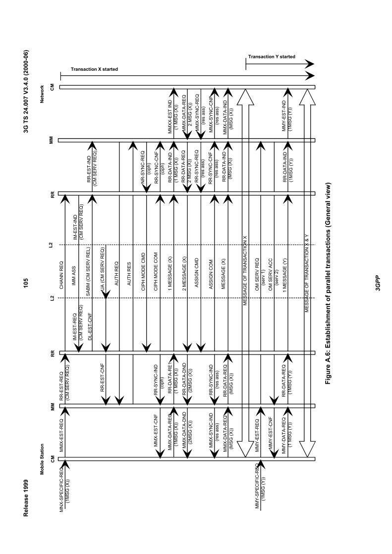
3GPP
3G T
S 24
.007
V3.
4.0
(200
0-06
)10
5R
elea
se 1
999
Mob
ile S
tatio
nN
etw
ork
MN
X-SP
ECIF
IC-R
EQ
(1
MSG
(X))
MM
X-ES
T-R
EQR
R-E
ST-R
EQ(C
M S
ERV
REQ
)
RR
-ES
T-C
NF
MM
X-ES
T-C
NF
RR
-SYN
C-IN
D
(ci
ph)
MM
X-D
ATA-
REQ
(1
MSG
(X))
MM
X-D
ATA-
DN
D
(2M
SG (X
))
RR
-DAT
A-R
E1(1
MSG
(X))
RR
-DA
TA-D
ND
(2M
SG (X
))
MM
X-SY
NC
-IND
(
res
ass)
MM
X-D
ATA-
REQ
(M
SG (X
))
MM
Y-ES
T-R
EQ
MM
Y-ES
T-C
NF
MM
Y-D
ATA-
REQ
(
1 M
SG (Y
))
RR
-SYN
C-IN
D
(re
s as
s)
RR
-DAT
A-R
EQ (
MSG
(X))
RR
-DAT
A-R
EQ (
1MSG
(Y))
CH
ANN
REQ
IMM
ASS
DL-
EST-
CN
F
UA
(CM
SER
V R
EQ)
AUTH
REQ
AUTH
RES
CIP
H M
OD
E C
MD
CIP
H M
OD
E C
OM
1 M
ESSA
GE
(X)
2 M
ESSA
GE
(X)
ASSI
GN
CM
D
ASSI
GN
CO
M
MES
SAG
E (X
)
MES
SAG
E O
F TR
ANSA
CTI
ON
X
OM
SER
V R
EQ
(s
erv
1)O
M S
ERV
ACC
(s
erv
2)
1 M
ESSA
GE
(Y)
MES
SAG
E O
F TR
ANSA
CTI
ON
X &
Y
R
R-E
ST-IN
D(C
M S
ERV
REQ
)
NR
-SYN
C-R
EQ
(c
iph)
RR
-SYN
C-C
NF
(cip
h)R
R-D
ATA-
IND
(1 M
SG (X
))R
R-D
ATA-
REQ
2 M
SG (X
))R
R-S
YNC
-REQ
(r
es a
ss)
RR
-SYN
C-C
NF
(
res
ass)
RR
-DAT
A-IN
D (
MSG
(X))
MM
X-D
ATA-
REQ
2
MSG
(X))
MM
X-SY
NC
-REQ
(
res
ass)
MM
X-SY
NC
-CN
F
(re
s as
s)
MM
X-D
ATA-
IND
(M
SG (X
))
MM
XX-E
ST IN
D
(1 M
SG (X
))
RR
-DAT
A-IN
D(1
MSG
(Y))
MM
Y-ES
T-IN
D(1
MSG
(Y))
Transaction Y started
Transaction X startedIM
-EST
-REQ
(CM
SER
V R
EQ)
IM-E
ST-IN
D(C
M S
ERV
REQ
)SA
BM (C
M S
ERV
REL
)
MM
Y-SP
ECIF
IC-R
EQ
(1
MSG
(Y))
CM
MM
RR
L2C
MM
MR
RL2
Figu
re A
.6: E
stab
lishm
ent o
f par
alle
l tra
nsac
tions
(Gen
eral
vie
w)
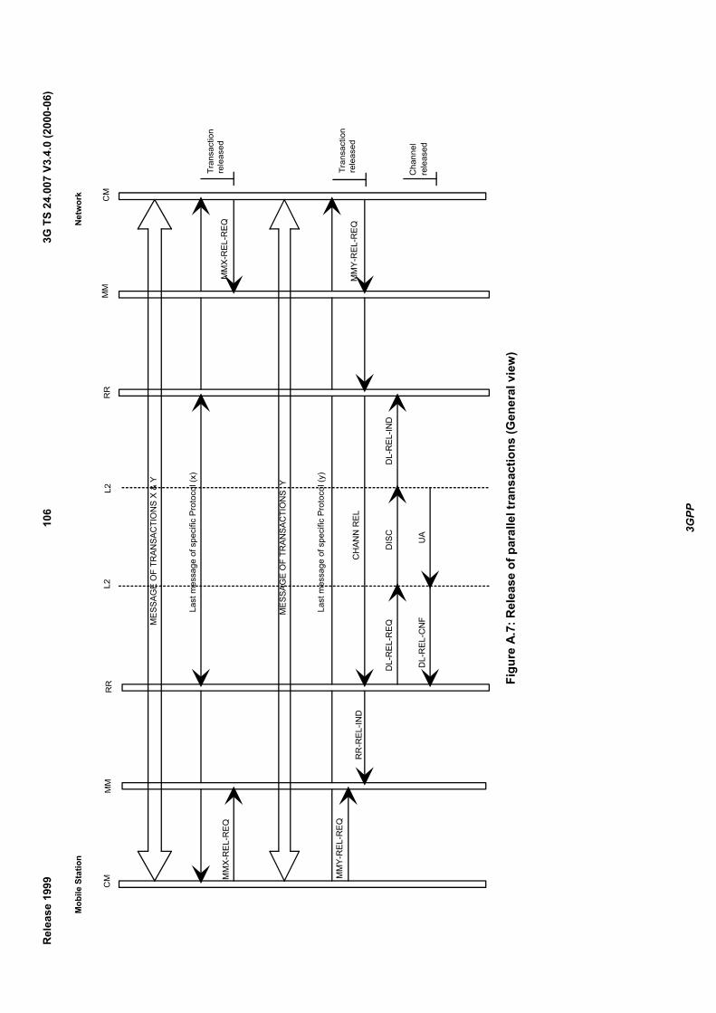
3GPP
3G T
S 24
.007
V3.
4.0
(200
0-06
)10
6R
elea
se 1
999
Mob
ile S
tatio
nN
etw
ork
MM
X-R
EL-R
EQ
MM
Y-R
EL-R
EQ
RR
-REL
-IND
Last
mes
sage
of s
peci
fic P
roto
col (
x)
MES
SAG
E O
F TR
ANSA
CTI
ON
S X
& Y
MES
SAG
E O
F TR
ANSA
CTI
ON
S Y
Last
mes
sage
of s
peci
fic P
roto
col (
y)
CH
ANN
REL
DL-
REL
-REQ
DL-
REL
-CN
F
DIS
C
UA
DL-
REL
-IND
MM
X-R
EL-R
EQ
MM
Y-R
EL-R
EQ
Tran
sact
ion
re
leas
ed
Tran
sact
ion
re
leas
ed
Cha
nnel
rele
ased
CM
MM
RR
L2C
MM
MR
RL2
Figu
re A
.7: R
elea
se o
f par
alle
l tra
nsac
tions
(Gen
eral
vie
w)
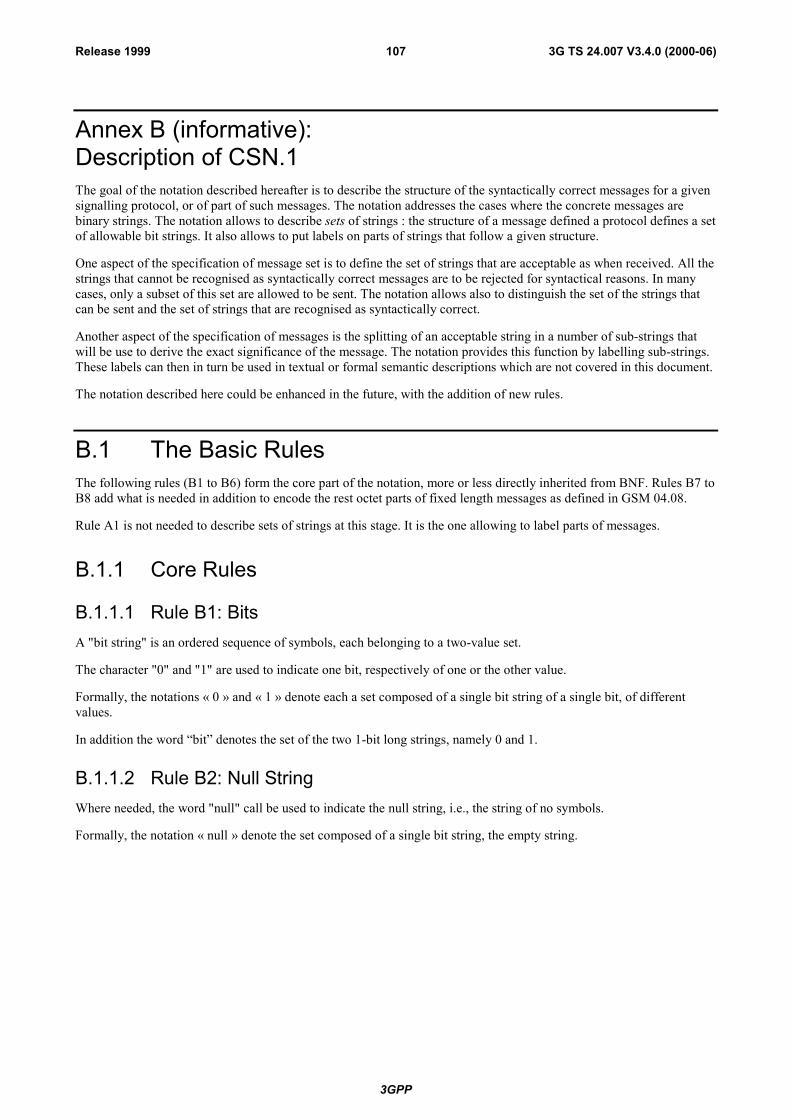
3GPP
3G TS 24.007 V3.4.0 (2000-06)107Release 1999
Annex B (informative):Description of CSN.1The goal of the notation described hereafter is to describe the structure of the syntactically correct messages for a givensignalling protocol, or of part of such messages. The notation addresses the cases where the concrete messages arebinary strings. The notation allows to describe sets of strings : the structure of a message defined a protocol defines a setof allowable bit strings. It also allows to put labels on parts of strings that follow a given structure.
One aspect of the specification of message set is to define the set of strings that are acceptable as when received. All thestrings that cannot be recognised as syntactically correct messages are to be rejected for syntactical reasons. In manycases, only a subset of this set are allowed to be sent. The notation allows also to distinguish the set of the strings thatcan be sent and the set of strings that are recognised as syntactically correct.
Another aspect of the specification of messages is the splitting of an acceptable string in a number of sub-strings thatwill be use to derive the exact significance of the message. The notation provides this function by labelling sub-strings.These labels can then in turn be used in textual or formal semantic descriptions which are not covered in this document.
The notation described here could be enhanced in the future, with the addition of new rules.
B.1 The Basic RulesThe following rules (B1 to B6) form the core part of the notation, more or less directly inherited from BNF. Rules B7 toB8 add what is needed in addition to encode the rest octet parts of fixed length messages as defined in GSM 04.08.
Rule A1 is not needed to describe sets of strings at this stage. It is the one allowing to label parts of messages.
B.1.1 Core Rules
B.1.1.1 Rule B1: BitsA "bit string" is an ordered sequence of symbols, each belonging to a two-value set.
The character "0" and "1" are used to indicate one bit, respectively of one or the other value.
Formally, the notations « 0 » and « 1 » denote each a set composed of a single bit string of a single bit, of differentvalues.
In addition the word �bit� denotes the set of the two 1-bit long strings, namely 0 and 1.
B.1.1.2 Rule B2: Null StringWhere needed, the word "null" call be used to indicate the null string, i.e., the string of no symbols.
Formally, the notation « null » denote the set composed of a single bit string, the empty string.
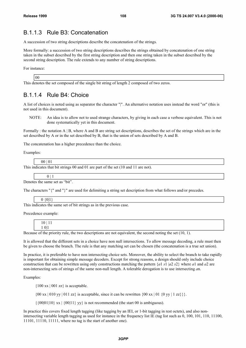
3GPP
3G TS 24.007 V3.4.0 (2000-06)108Release 1999
B.1.1.3 Rule B3: ConcatenationA succession of two string descriptions describe the concatenation of the strings.
More formally: a succession of two string descriptions describes the strings obtained by concatenation of one stringtaken in the subset described by the first string description and then one string taken in the subset described by thesecond string description. The rule extends to any number of string descriptions.
For instance:
00This denotes the set composed of the single bit string of length 2 composed of two zeros.
B.1.1.4 Rule B4: ChoiceA list of choices is noted using as separator the character "|". An alternative notation uses instead the word "or" (this isnot used in this document).
NOTE: An idea is to allow not to used strange characters, by giving in each case a verbose equivalent. This is notdone systematically yet in this document.
Formally : the notation A | B, where A and B are string set descriptions, describes the set of the strings which are in theset described by A or in the set described by B, that is the union of sets described by A and B.
The concatenation has a higher precedence than the choice.
Examples:
00 | 01This indicates that bit strings 00 and 01 are part of the set (10 and 11 are not).
0 | 1Denotes the same set as �bit�.
The characters "{" and "}" are used for delimiting a string set description from what follows and/or precedes.
0 {0|1}This indicates the same set of bit strings as in the previous case.
Precedence example:
10 | 111 0|1
Because of the priority rule, the two descriptions are not equivalent, the second noting the set (10, 1).
It is allowed that the different sets in a choice have non null intersections. To allow message decoding, a rule must thenbe given to choose the branch. The rule is that any matching set can be chosen (the concatenation is a true set union).
In practice, it is preferable to have non intersecting choice sets. Moreover, the ability to select the branch to take rapidlyis important for obtaining simple message decoders. Except for strong reasons, a design should only include choiceconstruction that can be rewritten using only constructions matching the pattern {a1 s1 |a2 s2} where a1 and a2 arenon-intersecting sets of strings of the same non-null length. A tolerable derogation is to use intersecting an.
Examples:
{100 xx | 001 zz} is acceptable.
{00 xx | 010 yy | 011 zz} is acceptable, since it can be rewritten {00 xx | 01 {0 yy | 1 zz}}}.
{{00|01|10} xx | {00|11} yy} is not recommended (the start 00 is ambiguous).
In practice this covers fixed length tagging (like tagging by an IEI, or 1-bit tagging in rest octets), and also non-intersecting variable length tagging as used for instance in the frequency list IE (tag list such as 0, 100, 101, 110, 11100,11101, 11110, 11111, where no tag is the start of another one).
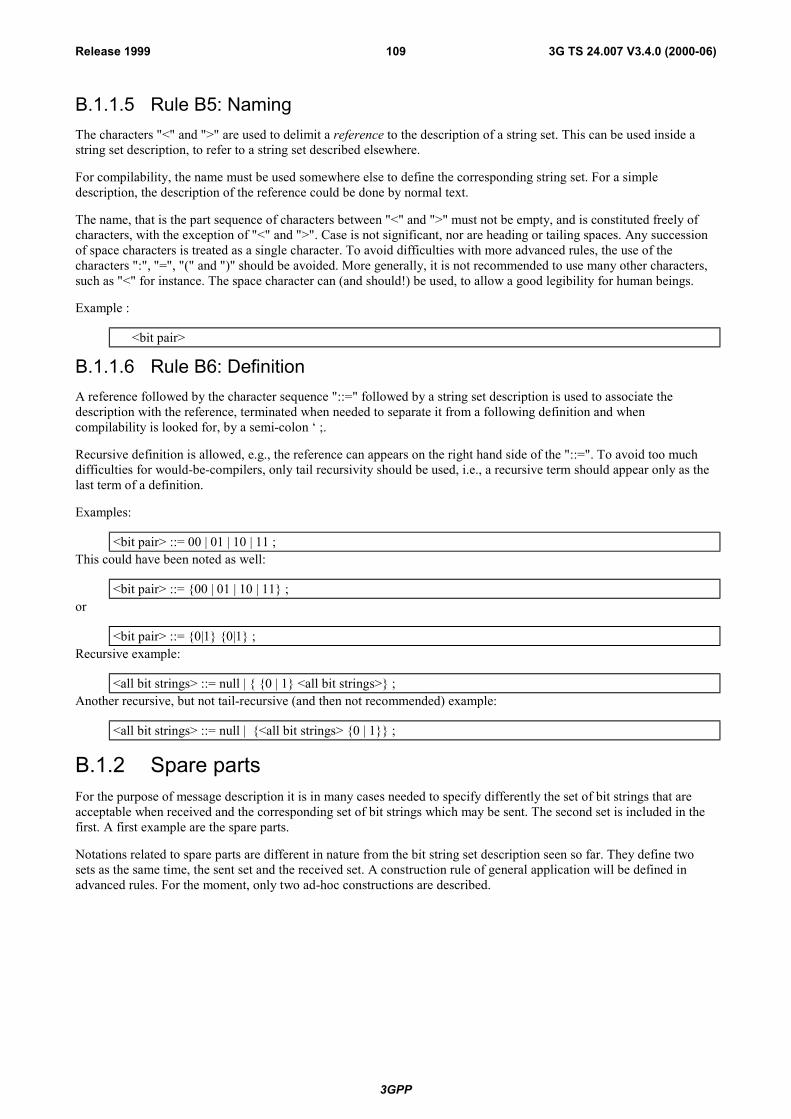
3GPP
3G TS 24.007 V3.4.0 (2000-06)109Release 1999
B.1.1.5 Rule B5: NamingThe characters "<" and ">" are used to delimit a reference to the description of a string set. This can be used inside astring set description, to refer to a string set described elsewhere.
For compilability, the name must be used somewhere else to define the corresponding string set. For a simpledescription, the description of the reference could be done by normal text.
The name, that is the part sequence of characters between "<" and ">" must not be empty, and is constituted freely ofcharacters, with the exception of "<" and ">". Case is not significant, nor are heading or tailing spaces. Any successionof space characters is treated as a single character. To avoid difficulties with more advanced rules, the use of thecharacters ":", "=", "(" and ")" should be avoided. More generally, it is not recommended to use many other characters,such as "<" for instance. The space character can (and should!) be used, to allow a good legibility for human beings.
Example :
<bit pair>
B.1.1.6 Rule B6: DefinitionA reference followed by the character sequence "::=" followed by a string set description is used to associate thedescription with the reference, terminated when needed to separate it from a following definition and whencompilability is looked for, by a semi-colon � ;.
Recursive definition is allowed, e.g., the reference can appears on the right hand side of the "::=". To avoid too muchdifficulties for would-be-compilers, only tail recursivity should be used, i.e., a recursive term should appear only as thelast term of a definition.
Examples:
<bit pair> ::= 00 | 01 | 10 | 11 ;This could have been noted as well:
<bit pair> ::= {00 | 01 | 10 | 11} ;or
<bit pair> ::= {0|1} {0|1} ;Recursive example:
<all bit strings> ::= null | { {0 | 1} <all bit strings>} ;Another recursive, but not tail-recursive (and then not recommended) example:
<all bit strings> ::= null | {<all bit strings> {0 | 1}} ;
B.1.2 Spare partsFor the purpose of message description it is in many cases needed to specify differently the set of bit strings that areacceptable when received and the corresponding set of bit strings which may be sent. The second set is included in thefirst. A first example are the spare parts.
Notations related to spare parts are different in nature from the bit string set description seen so far. They define twosets as the same time, the sent set and the received set. A construction rule of general application will be defined inadvanced rules. For the moment, only two ad-hoc constructions are described.
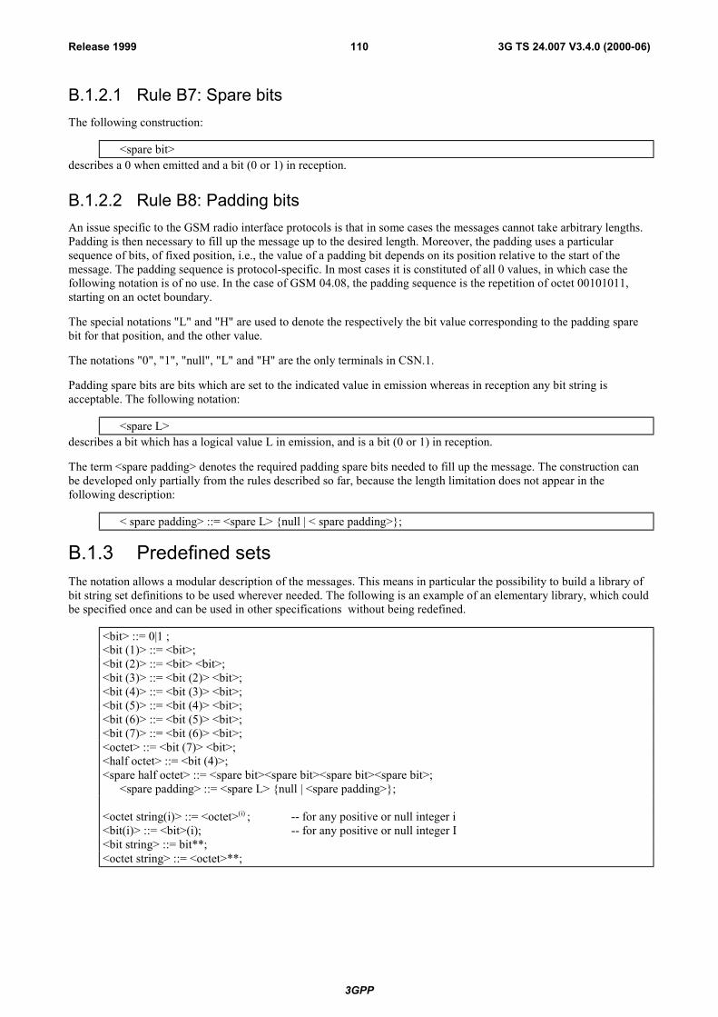
3GPP
3G TS 24.007 V3.4.0 (2000-06)110Release 1999
B.1.2.1 Rule B7: Spare bitsThe following construction:
<spare bit>describes a 0 when emitted and a bit (0 or 1) in reception.
B.1.2.2 Rule B8: Padding bitsAn issue specific to the GSM radio interface protocols is that in some cases the messages cannot take arbitrary lengths.Padding is then necessary to fill up the message up to the desired length. Moreover, the padding uses a particularsequence of bits, of fixed position, i.e., the value of a padding bit depends on its position relative to the start of themessage. The padding sequence is protocol-specific. In most cases it is constituted of all 0 values, in which case thefollowing notation is of no use. In the case of GSM 04.08, the padding sequence is the repetition of octet 00101011,starting on an octet boundary.
The special notations "L" and "H" are used to denote the respectively the bit value corresponding to the padding sparebit for that position, and the other value.
The notations "0", "1", "null", "L" and "H" are the only terminals in CSN.1.
Padding spare bits are bits which are set to the indicated value in emission whereas in reception any bit string isacceptable. The following notation:
<spare L>describes a bit which has a logical value L in emission, and is a bit (0 or 1) in reception.
The term <spare padding> denotes the required padding spare bits needed to fill up the message. The construction canbe developed only partially from the rules described so far, because the length limitation does not appear in thefollowing description:
< spare padding> ::= <spare L> {null | < spare padding>};
B.1.3 Predefined setsThe notation allows a modular description of the messages. This means in particular the possibility to build a library ofbit string set definitions to be used wherever needed. The following is an example of an elementary library, which couldbe specified once and can be used in other specifications without being redefined.
<bit> ::= 0|1 ;<bit (1)> ::= <bit>;<bit (2)> ::= <bit> <bit>;<bit (3)> ::= <bit (2)> <bit>;<bit (4)> ::= <bit (3)> <bit>;<bit (5)> ::= <bit (4)> <bit>;<bit (6)> ::= <bit (5)> <bit>;<bit (7)> ::= <bit (6)> <bit>;<octet> ::= <bit (7)> <bit>;<half octet> ::= <bit (4)>;<spare half octet> ::= <spare bit><spare bit><spare bit><spare bit>;
<spare padding> ::= <spare L> {null | <spare padding>};
<octet string(i)> ::= <octet>(i) ; -- for any positive or null integer i<bit(i)> ::= <bit>(i); -- for any positive or null integer I<bit string> ::= bit**;<octet string> ::= <octet>**;
3GPP
3G TS 24.007 V3.4.0 (2000-06)111Release 1999
NOTE 1: The definition of generic constructions such as <bit string(i)> is somewhat cumbersome with only the basicrules. More advanced rules would allow a much more compact notation.
NOTE 2: The use of the characters "(" and ")" within a reference is done consistently with potential advanced rules.NOTE 3: This basic library is not exhaustive and can be extended when the needs arise.
B.1.4 Labelling Parts
B.1.4.1 Rule A1: LabelsDelimited names as defined by Rule B6 identify sets of sub strings. In many cases this can be used within the context ofa message to refer to the specific part of the message. However, this is not of general application, since it may happenthat two parts of a message follow the same structure, and economy of notation requires that the structure is describedbut once.
The general syntax that follows allows to refer to a part inside a description:
<name1 : string description>
For the definition of string sets, this is equivalent to the string description being used alone.
The name used as a label can be built according to the rules applicable to parenthesed references.
Examples:
<Tag : 000 > <Field : <Field type>> <Field : octet>
The third example shows the use of a non parentheses reference to obtain a more elegant expression than, for instance,the second example. At this stage, labels has no use for describing message syntax, but can be used to refer to thecorresponding part of the string, e.g., in the description of the message specifying the relationship between thesyntactical content and the semantical contents of the message, or to associate properties with effective sub-strings ineffective messages (rather than with sets of sub strings). Syntactical use of the semantical identifier are presented inmore advanced rules.
The same name may appear in several places. Designers have to be careful to use non ambiguous names ifnon-ambiguous reference is desired.
B.1.5 Goodies
B.1.5.1 Rule G1: CommentsComments can be added, starting with the term "--" and ended by the end of line. Comments can be used in particular toindicate the section where a particular description can be found.
B.2 Advanced rules
B.2.1 Rule A2: Exponent notationAn arithmetic expression used as exponent after a delimited string description is used to indicate repetitions.
A numerical expression between parentheses indicates a fixed number of repetitions.
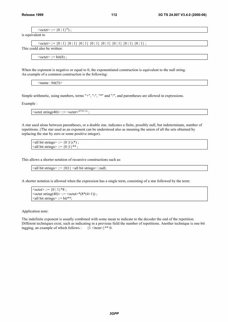
3GPP
3G TS 24.007 V3.4.0 (2000-06)112Release 1999
<octet> ::= {0 | 1}(8) ;is equivalent to
<octet> ::= {0 | 1} {0 | 1} {0 | 1} {0 | 1} {0 | 1} {0 | 1} {0 | 1} {0 | 1} ;This could also be written:
<octet> ::= bit(8) ;
When the exponent is negative or equal to 0, the exponentiated construction is equivalent to the null string.An example of a common construction is the following:
<name : bit(5)>
Simple arithmetic, using numbers, terms "+", "-", "*" and "/", and parentheses are allowed in expressions.
Example :
<octet string(40)> ::= <octet>(8*(4+1)) ;
A star used alone between parentheses, or a double star, indicates a finite, possibly null, but indeterminate, number ofrepetitions. (The star used as an exponent can be understood also as meaning the union of all the sets obtained byreplacing the star by zero or some positive integer).
<all bit strings> ::= {0 |1}(*) ;<all bit strings> ::= {0 |1}** ;
This allows a shorter notation of recursive constructions such as:
<all bit strings> ::= {0|1} <all bit strings> | null;
A shorter notation is allowed when the expression has a single term, consisting of a star followed by the term:
<octet> ::= {0 | 1}*8 ;<octet string(40)> ::= <octet>*(8*(4+1)) ;<all bit strings> ::= bit**;
Application note:
The indefinite exponent is usually combined with some mean to indicate to the decoder the end of the repetition.Different techniques exist, such as indicating in a previous field the number of repetitions. Another technique is one-bittagging, an example of which follows : {1 <item>}** 0.

3GPP
3G TS 24.007 V3.4.0 (2000-06)113Release 1999
Annex C (informative):GPRS-Services sequence diagramInstead of providing a complete set of all scenarios, the intention of this section is to provide some typical examples. Itshall be noted, that within the figures only those parameters of the PDUs and the service primitives are shown, whichare needed for a general understanding of the examples. Furthermore during the examples below (except C.17) no cellre-selection takes place.
C.1 ATTACH, GPRS only, MS unknown in the network
GMMREG-ATTACH- REQ
[Attach type, READY-timer, STANDBY-timer ]
START TattachLL-UNITDATA-REQ
[PDU=Attach Req ( IMSI or TLLIplusRAI), oldTLLI,Cipher=off ]
GRR-DATA-REQ
[LLC-UI, SAPI=signalling]
GRR-DATA-IND
[LLC-UI, TLLI,RAI,CI]
LL-UNITDATA-IND
[PDU=Attach Req ( IMSI or TLLIplusRAI), oldTLLI, CI]
LLGMM-ASSIGN-REQ
[Kc, Algorithm]
START Tauth
LL-UNITDATA-REQGRR-DATA--REQ
STOP Tauth
[ PDU=Auth-Cipher- Req (Alg, RAND,..),oldTLLI, Cipher=off ]
[LLC-UI,DRX, CLM,SAPI=signalling]
GRR-DATA-IND
[LLC-UI]
LL-UNITDATA-IND
[PDU=Auth-Cipher- Req (Alg., RAND,�)]
LL-UNITDATA-REQ
[PDU=Auth-Cipher- Resp (SRES), oldTLLI,Cipher=off ]
GRR-DATA-REQ
[LLC-UI, SAPI=signalling]
GRR-DATA-IND
[LLC-UI, oldTLLI]
LL-UNITDATA-IND
[PDU=Auth-Cipher- Resp (SRES), oldTLLI ]
[Kc, Algorithm]
MS NET
GMMSNDCP LLC RR SM SNDCPLLCRR BSSGPSM GMM
LLGMM-ASSIGN-REQ
START Tident
LL-UNITDATA-REQ
[ PDU=Identification Req,oldTLLI, Cipher=off ]
GRR-DATA--REQ
[LLC-UI,DRX, CLM,SAPI=signalling]
GRR-DATA-IND
[LLC-UI]
LL-UNITDATA-IND
[PDU=Identification Req]
STOP Tident
LL-UNITDATA-REQ
[PDU=Identification- Resp (IMSI), oldTLLI,Cipher=off ]
GRR-DATA-REQ
[LLC-UI, SAPI=signalling]
GRR-DATA-IND
[LLC-UI, TLLI]
LL-UNITDATA-IND
[PDU=Identification- Resp (IMSI), oldTLLI ]
The oldTLLI may be aLocal TLLI, or aForeign TLLI, or aRandom TLLI
IMSI fetched if- No GPRS MM Context exists, and- Attach Request without IMSI
The network starts theauthentication together with settingthe ciphering mode.
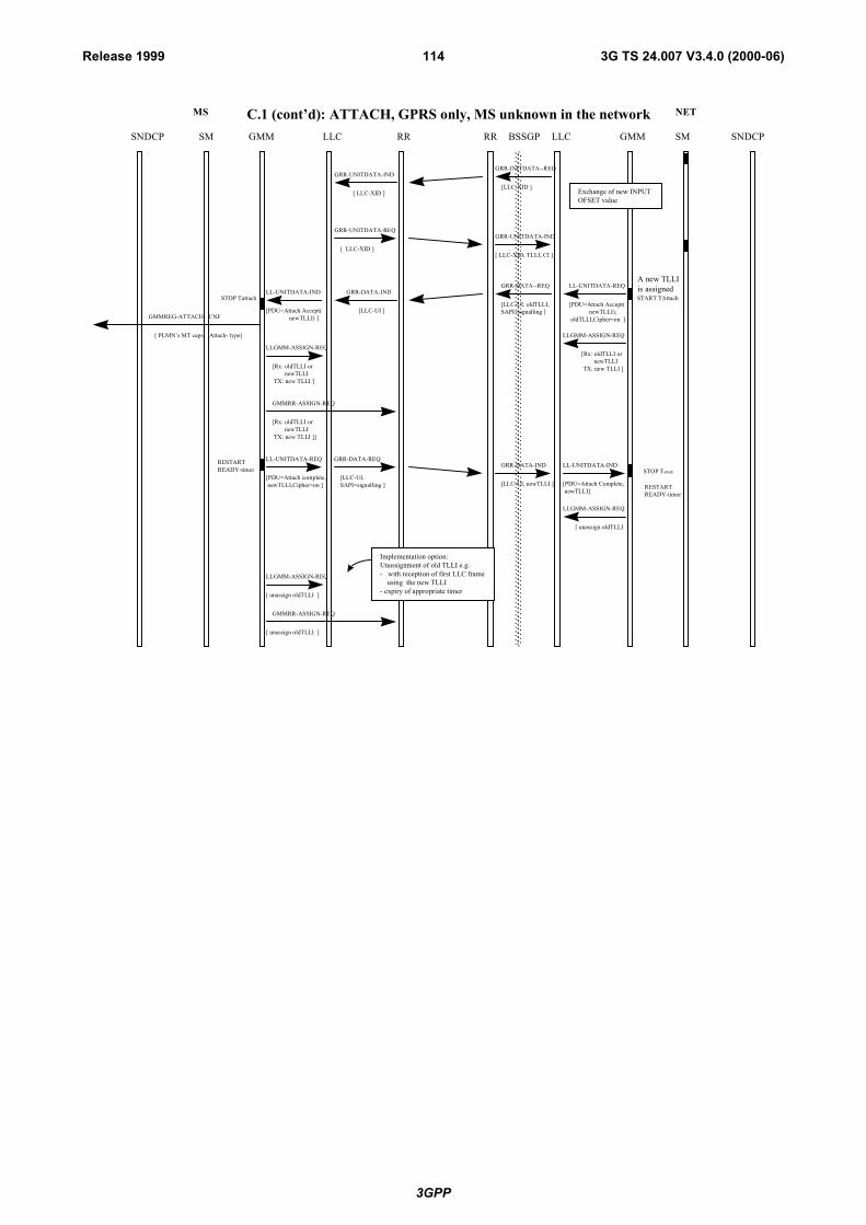
3GPP
3G TS 24.007 V3.4.0 (2000-06)114Release 1999
MS NET
GMMSNDCP LLC RR SM SNDCPLLCRR BSSGPSM GMM
C.1 (cont�d): ATTACH, GPRS only, MS unknown in the network
START TAttachSTOP Tattach
GMMREG-ATTACH- CNF
[ PLMN�s MT caps, Attach- type]
STOP Tattach
LL-UNITDATA-REQ
[PDU=Attach Accept( newTLLI), oldTLLI,Cipher=on ]
GRR-DATA--REQ
[LLC-UI, oldTLLI, SAPI=signalling ]
GRR-DATA-IND
[LLC-UI ]
LL-UNITDATA-IND
[PDU=Attach Accept( newTLLI) ]
LLGMM-ASSIGN-REQ
[Rx: oldTLLI or newTLLI TX: new TLLI ]
LLGMM-ASSIGN-REQ
[Rx: oldTLLI or newTLLI TX: new TLLI ]
LL-UNITDATA-REQ
[PDU=Attach complete, newTLLI,Cipher=on ]
GRR-DATA-REQ
[LLC-UI, SAPI=signalling ]
GRR-DATA-IND
[LLC-UI, newTLLI ]
LL-UNITDATA-IND
[PDU=Attach Complete, newTLLI]
[ unassign oldTLLI ]
LLGMM-ASSIGN-REQ
GMMRR-ASSIGN-REQ
[Rx: oldTLLI or newTLLI TX: new TLLI ]]
RESTARTREADY-timer
RESTARTREADY-timer
LLGMM-ASSIGN-REQ
[ unassign oldTLLI ]
GMMRR-ASSIGN-REQ
[ unassign oldTLLI ]
A new TLLI is assigned
Implementation option:Unassignment of old TLLI e.g.- with reception of first LLC frame using the new TLLI- expiry of appropriate timer
GRR-INITDATA--REQ
[LLC-XID ]
GRR-UNITDATA-IND
[ LLC-XID, TLLI, CI ]
GRR-UNITDATA-IND
[ LLC-XID ]
GRR-UNITDATA-REQ
[ LLC-XID ]
Exchange of new INPUTOFSET value
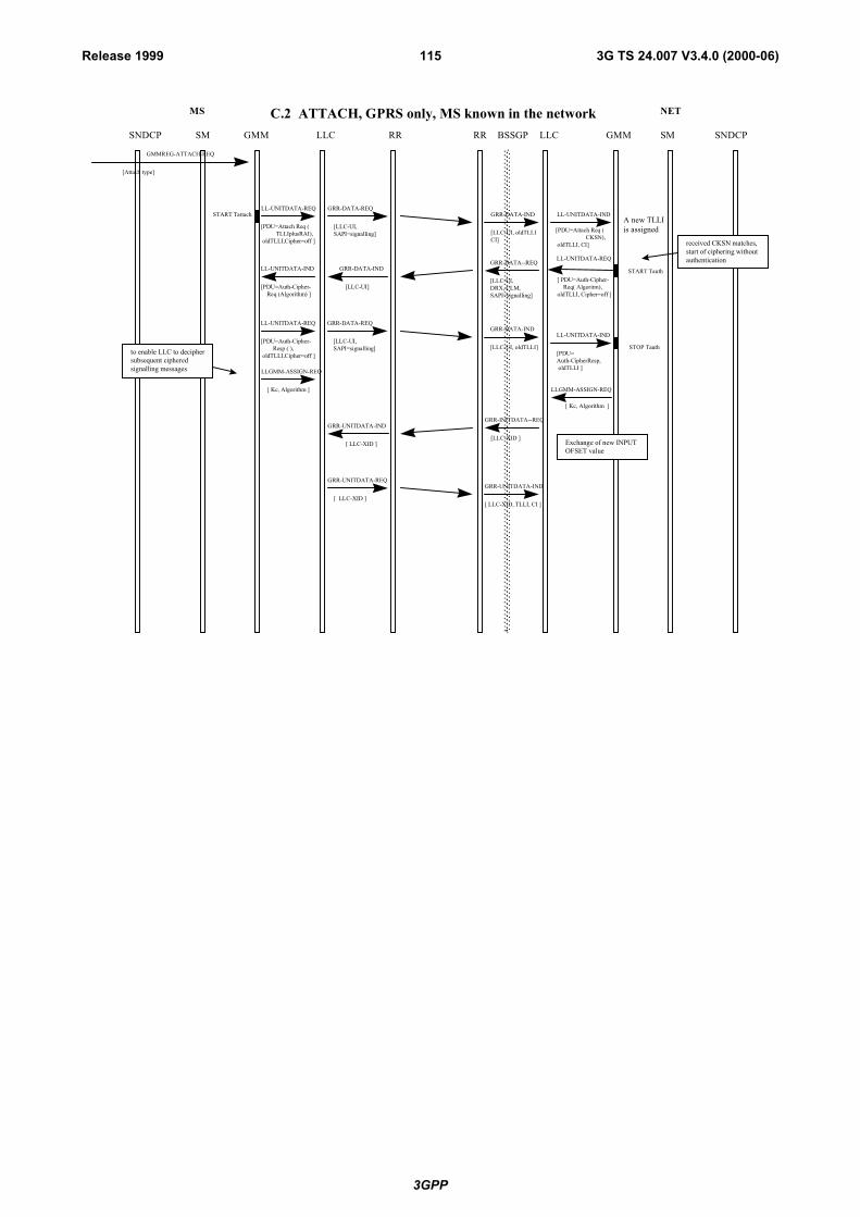
3GPP
3G TS 24.007 V3.4.0 (2000-06)115Release 1999
C.2 ATTACH, GPRS only, MS known in the network
GMMREG-ATTACH-REQ
[Attach type]
START TattachLL-UNITDATA-REQ GRR-DATA-REQ
[LLC-UI, SAPI=signalling]
GRR-DATA-IND
[LLC-UI, oldTLLICI]
LL-UNITDATA-IND
[PDU=Attach Req ( CKSN), oldTLLI, CI]
A new TLLI is assigned
MS NET
GMMSNDCP LLC RR SM SNDCPLLCRR BSSGPSM GMM
[PDU=Attach Req ( TLLIplusRAI), oldTLLI,Cipher=off ]
START Tauth
LL-UNITDATA-REQGRR-DATA--REQ
STOP Tauth
[ PDU=Auth-Cipher- Req( Algoritm),oldTLLI, Cipher=off ]
[LLC-UI,DRX, CLM,SAPI=signalling]
GRR-DATA-IND
[LLC-UI]
LL-UNITDATA-IND
[PDU=Auth-Cipher- Req (Algorithm) ]
LL-UNITDATA-REQ
[PDU=Auth-Cipher- Resp ( ), oldTLLI,Cipher=off ]
GRR-DATA-REQ
[LLC-UI, SAPI=signalling]
GRR-DATA-IND
[LLC-UI, oldTLLI]
LL-UNITDATA-IND
[PDU=Auth-CipherResp, oldTLLI ]LLGMM-ASSIGN-REQ
[ Kc, Algorithm ]
to enable LLC to deciphersubsequent cipheredsignalling messages
received CKSN matches,start of ciphering withoutauthentication
[ Kc, Algorithm ]
LLGMM-ASSIGN-REQ
GRR-INITDATA--REQ
[LLC-XID ]
GRR-UNITDATA-IND
[ LLC-XID, TLLI, CI ]
GRR-UNITDATA-IND
[ LLC-XID ]
GRR-UNITDATA-REQ
[ LLC-XID ]
Exchange of new INPUTOFSET value

3GPP
3G TS 24.007 V3.4.0 (2000-06)116Release 1999
C.2 (cont�d) ATTACH, GPRS only, MS known in the network
START TattachSTOP TattachGMMREG-ATTACH-CNF
[ PLMN�s MT caps, Attach- type]
LL-UNITDATA-REQ
[PDU=Attach Accept( newTLLI), oldTLLI, Cipher=on ]
GRR-DATA-REQ
[LLC-UI, SAPI=signalling ]
GRR-DATA-IND
[LLC-UI ]
LL-UNITDATA-IND
[PDU= Attach Accept( new TLLI) ]
LLGMM-ASSIGN-REQLLGMM-ASSIGN-REQ
[Rx: oldTLLI or newTLLI TX: new TLLI , Kc, Algorithm ]
STOP Tattach
[ Rx: old or newTLLI TX: new TLLI ] ]
LL-UNITDATA-REQ
[PDU=Attach complete, newTLLI, Cipher=on ]
GRR-DATA-REQ
[LLC-UI, SAPI=signalling ]
GRR-DATA-IND
[LLC-UI, newTLLI ]
LL-UNITDATA-IND
[PDU=Attach Complete, newTLLI]
[ unassign oldTLI ]
LLGMM-ASSIGN-REQ
GMMRR-ASSIGN- REQ
RESTARTREADY-timer
RESTARTREADY-timer
MS NET
GMMSNDCP LLC RR SM SNDCPLLCRR BSSGPSM GMM
LLGMM-ASSIGN-REQ
[ unassign oldTLLI ]
GMMRR-ASSIGN-REQ
[ unassign oldTLLI ]
[Kc, Algorithm ]
[ Rx: old or newTLLI TX: new TLLI ] ]
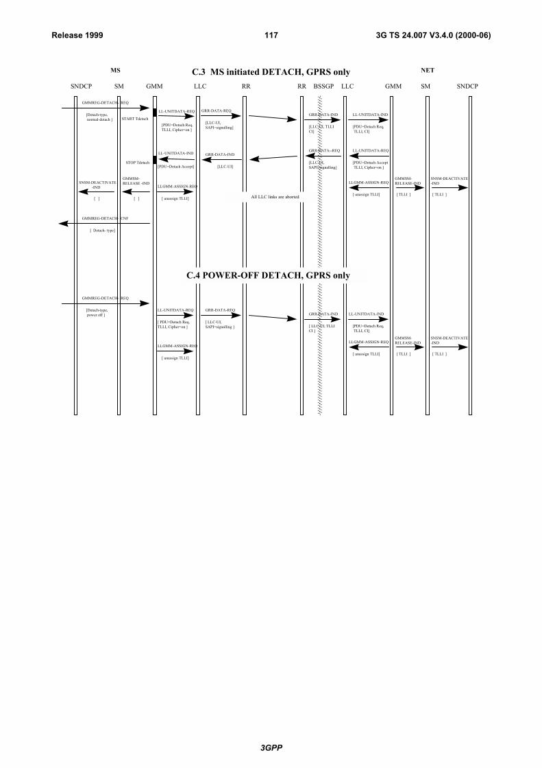
3GPP
3G TS 24.007 V3.4.0 (2000-06)117Release 1999
MS NET
GMMSNDCP LLC RR SM SNDCPLLCRR BSSGPSM GMM
C.3 MS initiated DETACH, GPRS only
GMMREG-DETACH- REQ
[Detach-type, normal-detach ] START Tdetach
LL-UNITDATA-REQ
[PDU=Detach Req,TLLI, Cipher=on ]
GRR-DATA-REQ
[LLC-UI, SAPI=signalling]
GRR-DATA-IND
[LLC-UI, TLLICI]
LL-UNITDATA-IND
[PDU=Detach Req, TLLI, CI]
STOP Tdetach
GMMREG-DETACH- CNF
[ Detach- type]
LL-UNITDATA-REQ
[PDU=Detach Accept TLLI, Cipher=on ]
GRR-DATA--REQ
[LLC-UI, SAPI=signalling]
GRR-DATA-IND
[LLC-UI]
LL-UNITDATA-IND
[PDU=Detach Accept]
LL-UNITDATA-REQ
[ PDU=Detach Req,TLLI, Cipher=on ]
GRR-DATA-REQ
[ LLC-UI, SAPI=signalling ]
GRR-DATA-IND
[ LLC-UI, TLLICI ]
LL-UNITDATA-IND
[PDU=Detach Req, TLLI, CI]
C.4 POWER-OFF DETACH, GPRS only
LLGMM-ASSIGN-REQ
[ unassign TLLI] All LLC links are aborted
SNSM-DEACTIVATE -IND
[ ]
GMMSM-RELEASE -IND
[ ]
LLGMM-ASSIGN-REQ
[ unassign TLLI]
SNSM-DEACTIVATE-IND
[ TLLI ]
GMMSM-RELEASE-IND
[ TLLI ]
GMMREG-DETACH- REQ
[Detach-type, power off ]
LLGMM-ASSIGN-REQ
[ unassign TLLI]
SNSM-DEACTIVATE-IND
[ TLLI ]
GMMSM-RELEASE-IND
[ TLLI ]
LLGMM-ASSIGN-REQ
[ unassign TLLI]
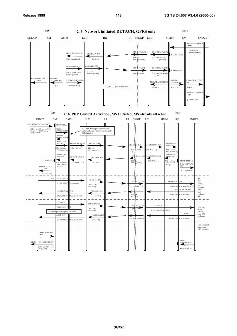
3GPP
3G TS 24.007 V3.4.0 (2000-06)118Release 1999
MS NET
GMMSNDCP LLC RR SM SNDCPLLCRR BSSGPSM GMM
C.5 Network initiated DETACH, GPRS only
GMMREG-DETACH- REQ
[Detach-type, normal-detach ]
LL-UNITDATA-REQ
[PDU=Detach Accept,TLLI, Cipher=on ]
GRR-DATA-REQ
[LLC-UI, SAPI=signalling]
GRR-DATA-IND
[LLC-UI, TLLICI]
LL-UNITDATA-IND
[PDU=Detach Accept, TLLI, CI]
STOP Tdetach
GMMREG-DETACH- CNF
[ Detach- type]
LL-UNITDATA-REQ
[PDU=Detach Req, TLLI , Cipher=on]
GRR-DATA-REQ
[LLC-UI, SAPI=signalling]
GRR-DATA-IND
[LLC-UI]
LL-UNITDATA-IND
[PDU=Detach Req]
LLGMM-ASSIGN-REQ
[ unassign TLLI] All LLC links are aborted
SNSM-DEACTIVATE -IND
[ ]
GMMSM-RELEASE -IND
[ ]
LLGMM-ASSIGN-REQ
[ unassign TLLI]
SNSM-DEACTIVATE-IND
[ TLLI ]
GMMSM-RELEASE-IND
[ TLLI ]
START Tdetach
C.6 PDP Context Activation, MS Initiated, MS already attached
GRR-DATA-REQLL-UNITDATA-REQ
[PDU=Activate PDP Context Req ]
[LLC-UI, SAPI=signalling]
GRR-DATA-IND
[LLC-UI, TLLICI]
LL-UNITDATA-IND
[SM-PDU, �..]
GRR-DATA--REQ
[LLC-UI, SAPI=signalling]
GRR-DATA-IND
[LLC-UI]
LL-UNITDATA-IND
[PDU= Activate PDP Context Accept ]
STOP TPDP Act
[ NSAPI, QoS ]
[ TLLI, NSAPI, QoS ]
SNSM-ACTIVATE -IND
SNSM-ACTIVATE-IND
START TPDPN act
No LLClinkexistsyet,establisha linkandexchangeXID
LLC linkexistsalready,only XIDexchange
SMREG- PDP-ACTIVATE-CNF
[ PDP-type, PDP-address, QoS, NSAPI]
SNSM-ACTIVATE-RSP
SNSM-ACTIVATE-CNF
[ ]
[ TLLI ]
STOP TPDPN act
LL-XID-REQ
[ TLLI, SNDCP XID ]
LL-XID-CNF
[ TLLI,SNDCP-XID negotiated, N201 ]
LL-XID-IND
[ TLLI, SNCP-XID, N201 ]
LL-XID-RSP
[ TLLI, SNCP-XID negotiated]
GRR-DATA-REQ
[ LLC-XID, SAPI=data ]
GRR-DATA-IND
[LLC XID]
GRR-DATA-IND
[ LLC XID, �..]
[LLC XID, priority=data]
LL- ESTABLISH-REQ
[ TLLI, SNDCP XID requested ]
LL-ESTABLISH- CNF
[ TLLI, SNDCP-XID negotiated, N201 ]
LL-ESTABLISH- IND
[ TLLI, SNCP-XID requested N201]
LL- ESTABLISH-RSP
[ TLLI, SNCP-XID negotiated ]
GRR-DATA-REQ
[ LLC-SABM, SAPI=data ]
GRR-DATA-IND
[LLC UA]
GRR-DATA-IND
[ LLC SABM, .....]
[LLC UA, SAPI=data]
LLC link existsalready, noXID exchange
MS NET
GMMSNDCP LLC RR SM SNDCPLLCRR BSSGPSM GMM
SMREG-PDP- ACTIVATE-REQ
[ PDP-type, PDP address, QoS,NSAPI, GGSN name, ACK/UNACK ]
START TPDPact
GMMSM-ESTABLISH-REQ
GMMSM-ESTABLISH-CNF
GMMSM-UNITDATA-IND
[PDU= Activate PDP Context Req ]
GMMSM-UNIT DATA-REQ
[SM-PDU, �.. ]
GMMSM-UNIT DATA-IND
[SM-PDU, �.. ]
LL-UNITDATA-REQ
[ PDU= Activate PDP Context Accept ]
[SM-PDU, �..]
GMMSM-UNITDATA-REQ
the GPRS Attach procedure shall beperformed in case the MS is not alreadyGPRS attached
XID re-negotiates requires link reset

3GPP
3G TS 24.007 V3.4.0 (2000-06)119Release 1999
C.7 PDP Context Activation, Network Initiated
RR-DATA-REQ
[ LLC-UI, SAPI=signalling ]
GRR-DATA-IND
[ LLC-UI, �.. ]
[ PDP- type, PDP address, QoS, NSAPI, GGSN name, ACK/UNACK ]
GRR-DATA--REQ
[ LLC-UI, SAPI=signalling ]
GRR-DATA-IND
[ LLC-UI ]
START TPDPN actSMREG-PDP-ACTIVATE-IND
STOP TPDPN act
MS NET
GMMSNDCP LLC RR SM SNDCPLLCRR BSSGPSM GMM
Continued as normal MS initiated PDP context activation
LL-UNITDATA-REQ
[ PDU= Request- PDP Context- Activation]
[SM-PDU, �..]
GMMSM-UNITDATA-REQ
SMREG-PDP-ACTIVATE-REQ
[ PDP-type, PDP-addressQoS, NSAPI,GGSN name, ACK/NACK ]
LL-UNITDATA-IND
[SM-PDU, �..]
GMMSM-UNITDATA-IND
[PDU= Activate PDP Context Req ]
LL-UNITDATA-REQ
[PDU=Activate PDP Context Req ]
SMREG-PDP- ACTIVATE-REQ
[ PDP-type, PDP address, QoS,NSAPI, GGSN name, ACK/UNACK ]
START TPDPact
GMMSM-UNIT DATA-REQ
[SM-PDU, �.. ]
LL-UNITDATA-IND
[PDU= Request- PDP Context- Activation]
GMMSM-UNIT DATA-IND
[SM-PDU, �.. ]

3GPP
3G TS 24.007 V3.4.0 (2000-06)120Release 1999
C.8 Anonymous PDP Context Activation
GRR-DATA-REQLL-UNITDATA-REQ
[PDU=Activate AA PDP Context Req ] [LLC-UI,
SAPI=signalling]
GRR-DATA-IND
[LLC-UI, TLLICI]
LL-UNITDATA-IND
[SM-PDU, �..]
GRR-DATA--REQ
[LLC-UI, SAPI=signalling]
GRR-DATA-IND
[LLC-UI]
LL-UNITDATA-IND
[PDU= Activate AA PDP Context Accept ]
STOP TPDP Act
[ NSAPI, QoS ]
[ TLLI, NSAPI, QoS ]
SNSM-ACTIVATE -IND
SNSM-ACTIVATE-IND
START TPDPN act
No LLClinkexistsyet,establisha linkandexchangeXID
LLC linkexistsalready,only XIDexchange
SMREG-AA-PDP-ACTIVATE-CNF
[ QoS]
SNSM-ACTIVATE-RSP
SNSM-ACTIVATE-CNF
[ ]
[ TLLI ]
STOP TPDPN act
LL-XID-REQ
[ TLLI, SNDCP XID ]
LL-XID-CNF
[ TLLI, SNDCP-XID neg otiated, N201 ]
LL-XID-IND
[ TLLI, SNCP-XID, N201 ]
LL-XID-RSP
[ SNCP-XID negotiated]
GRR-DATA-REQ
[ LLC-XID, SAPI=data ]
GRR-DATA-IND
[LLC XID]
GRR-DATA-IND
[ LLC XID, �..]
[LLC XID, priority=data]
LL- ESTABLISH-REQ
[ TLLI, SNDCP XID requested ]
LL-ESTABLISH- CNF
[ TLLI, SNDCP-XID negotiated, N201 ]
LL-ESTABLISH- IND
[ TLLI, SNCP-XID requested, N201 ]
LL- ESTABLISH-RSP
[ TLLI, SNCP-XID negotiated ]
GRR-DATA-REQ
[ LLC-SABM, SAPI=data ]
GRR-DATA-IND
[LLC UA]
GRR-DATA-IND
[ LLC SABM, .....]
[LLC UA, SAPI=data]
LLC link existsalready, noXID exchange
MS NET
GMMSNDCP LLC RR SM SNDCPLLCRR BSSGPSM GMM
SMREG-AA- PDP-ACTIVATE-REQ
[ server address, QoS, NSAPI,ACK/UNACK ]
START TPDPact
GMMAA-ESTABLISH-REQ
GMMSM-UNITDATA-IND
[PDU= Activate AA PDP Context Req ]
GMMSM-UNIT DATA-REQ
[SM-PDU, �.. ]
GMMSM-UNIT DATA-IND
[SM-PDU, �.. ]
LL-UNITDATA-REQ
[ PDU= Activate AA PDP Context Accept ]
[SM-PDU, �..]
GMMSM-UNITDATA-REQ
XID re-negotiates requires link reset
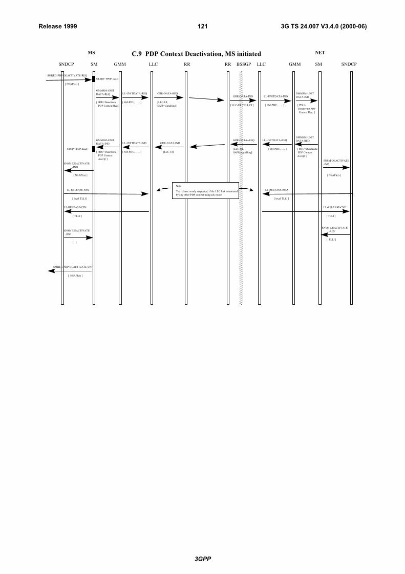
3GPP
3G TS 24.007 V3.4.0 (2000-06)121Release 1999
C.9 PDP Context Deactivation, MS initiated
SMREG-PDP-DEACTIVATE-REQ
[ NSAPI(s) ]
START TPDP deact
GRR-DATA-REQ
[LLC-UI,SAPI=signalling]
GRR-DATA-IND
[ LLC-UI, TLLI, CI ]
STOP TPDP deact
SMREG-PDP-DEACTIVATE-CNF
[ NSAPI(s) ]
[ PDU=Deactivate PDP ContextAccept ]
GRR-DATA--REQ
[LLC-UI,SAPI=signalling]
GRR-DATA-IND
[LLC-UI]
MS NET
GMMSNDCP LLC RR SM SNDCPLLCRR BSSGPSM GMM
LL-UNITDATA-REQ
[ PDU=Deactivate PDP Context Req ]
[ SM-PDU, �.. ]
GMMSM-UNITDATA-REQ
LL-UNITDATA-IND
[ PDU=Deactivate PDP Context Accept ]
[ SM-PDU, �.. ]
GMMSM-UNITDATA-IND
LL-UNITDATA-IND
[ PDU= Deactivate PDP Context Req ]
[ SM-PDU, �.. ]
GMMSM-UNITDATA-IND
LL-UNITDATA-REQ
[ SM-PDU, �.. ]
GMMSM-UNITDATA-REQ
[ NSAPI(s) ]
SNSM-DEACTIVATE -IND
SNSM-DEACTIVATE -RES
[ TLLI ]
[ TLLI ]
LL-RELEASE-CNF
LL-RELEASE-REQ
[ local TLLI ]
LL-RELEASE-CFN
[ TLLI ]
[ ]
SNSM-DEACTIVATE -RSP
[ NSAPI(s) ]
SNSM-DEACTIVATE-IND
LL-RELEASE-REQ
[ local TLLI ]
Note:
The release is only requested, if the LLC link is not usedby any other PDP context using ack mode
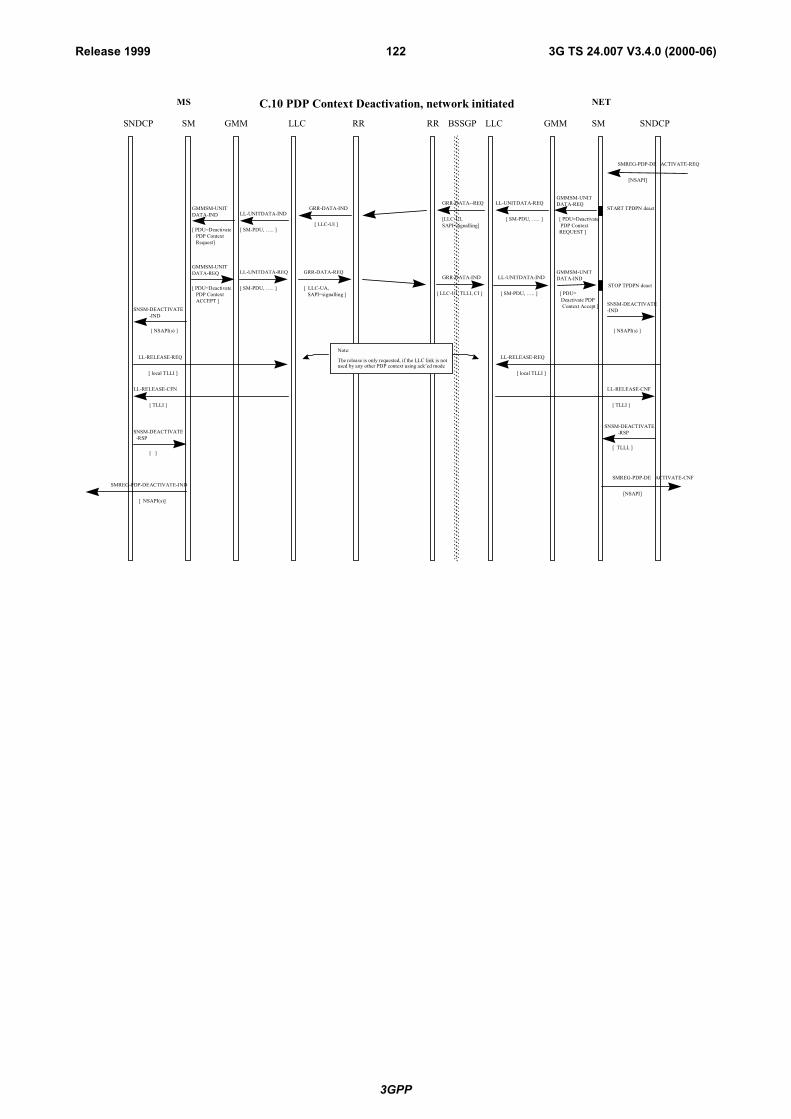
3GPP
3G TS 24.007 V3.4.0 (2000-06)122Release 1999
MS NET
GMMSNDCP LLC RR SM SNDCPLLCRR BSSGPSM GMM
C.10 PDP Context Deactivation, network initiated
START TPDPN deact
STOP TPDPN deact
SMREG-PDP-DEACTIVATE-IND
[ NSAPI(s)]
GRR-DATA--REQ
[LLC-UI,SAPI=signalling]
GRR-DATA-IND
[ LLC-UI, TLLI, CI ]
GRR-DATA-IND
[ LLC-UI ]
GRR-DATA-REQ
[ LLC-UA, SAPI=signalling ]
LL-UNITDATA-IND
[ PDU=Deactivate PDP Context Request]
[ SM-PDU, �.. ]
GMMSM-UNITDATA-IND
LL-UNITDATA-REQ
[ PDU=Deactivate PDP Context ACCEPT ]
[ SM-PDU, �.. ]
GMMSM-UNITDATA-REQ
LL-UNITDATA-REQ
[ SM-PDU, �.. ]
GMMSM-UNITDATA-REQ
[ PDU=Deactivate PDP ContextREQUEST ]
LL-UNITDATA-IND
[ PDU= Deactivate PDP Context Accept ]
[ SM-PDU, �.. ]
GMMSM-UNITDATA-IND
SMREG-PDP-DE ACTIVATE-CNF
[NSAPI]
SMREG-PDP-DE ACTIVATE-REQ
[NSAPI]
[ NSAPI(s) ]
SNSM-DEACTIVATE -IND
SNSM-DEACTIVATE -RSP
[ TLLI, ]
[ TLLI ]
LL-RELEASE-CNF
LL-RELEASE-REQ
[ local TLLI ]
LL-RELEASE-CFN
[ TLLI ]
[ ]
SNSM-DEACTIVATE -RSP
[ NSAPI(s) ]
SNSM-DEACTIVATE-IND
LL-RELEASE-REQ
[ local TLLI ]
Note:
The release is only requested, if the LLC link is notused by any other PDP context using ack�ed mode
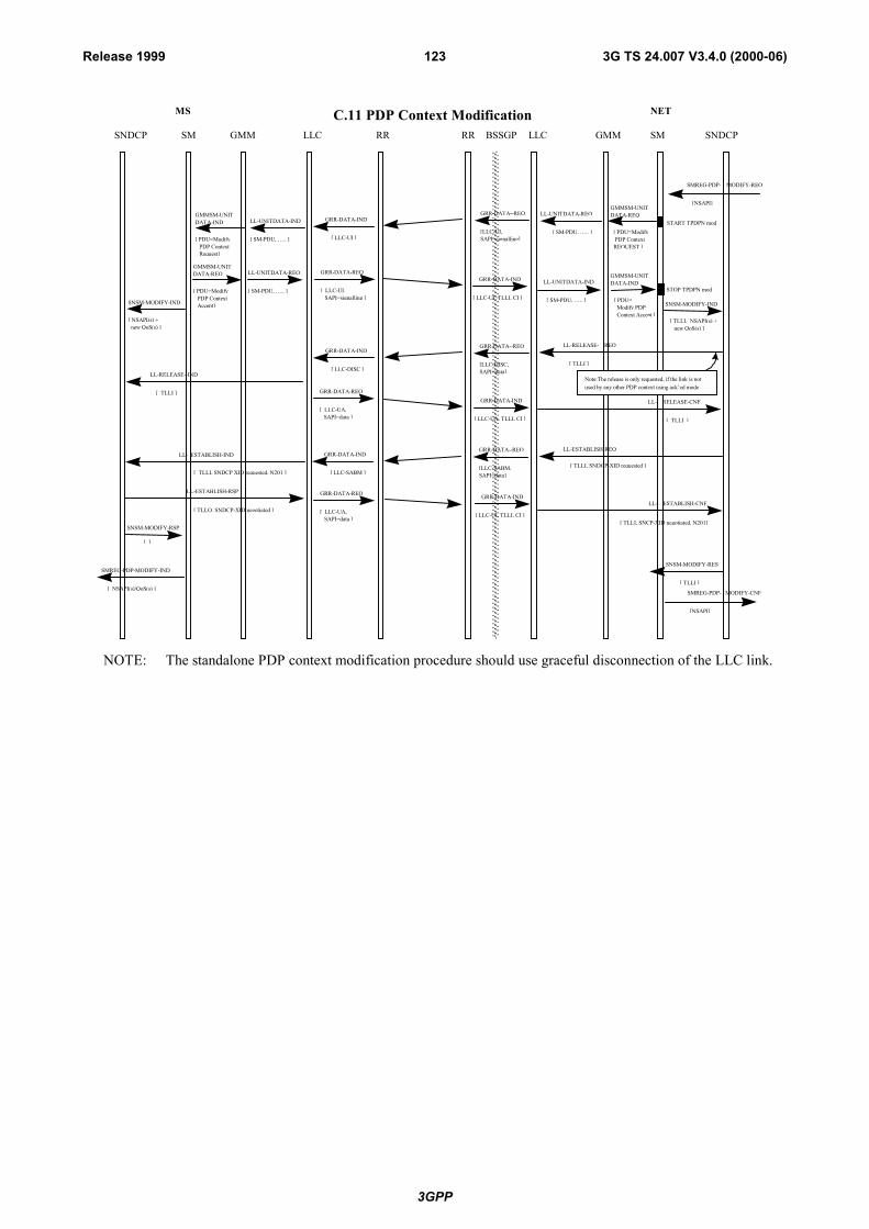
3GPP
3G TS 24.007 V3.4.0 (2000-06)123Release 1999
C.11 PDP Context Modification
START TPDPN mod
[ TLLI, NSAPI(s) + new QoS(s) ]
SNSM-MODIFY-IND
SNSM-MODIFY-RES
[ TLLI ]
STOP TPDPN mod
SMREG-PDP-MODIFY-IND
[ NSAPI(s)/QoS(s) ]
LL- ESTABLISH-IND
[ TLLI, SNDCP XID requested, N201 ]
LL-ESTABLISH-RSP
[ TLLO, SNDCP-XID negotiated ]LL- ESTABLISH-CNF
[ TLLI, SNCP-XID negotiated, N201]
[ NSAPI(s) + new QoS(s) ]
SNSM-MODIFY-IND
SNSM-MODIFY-RSP
[ ]
MS NET
GMMSNDCP LLC RR SM SNDCPLLCRR BSSGPSM GMM
GRR-DATA-IND
[ LLC-UI, TLLI, CI ]
GRR-DATA-IND
[ LLC-UA, TLLI, CI ]
GRR-DATA-IND
[ LLC-UI, TLLI, CI ]
GRR-DATA--REQ
[LLC-UI,SAPI=signalling]
GRR-DATA--REQ
[LLC-DISC,SAPI=data]
GRR-DATA--REQ
[LLC-SABM,SAPI=data]
GRR-DATA-IND
[ LLC-UI ]
GRR-DATA-IND
[ LLC-DISC ]
GRR-DATA-IND
[ LLC-SABM ]
GRR-DATA-REQ
[ LLC-UA, SAPI=data ]
GRR-DATA-REQ
[ LLC-UA, SAPI=data ]
GRR-DATA-REQ
[ LLC-UI, SAPI=signalling ]
LL-UNITDATA-REQ
[ SM-PDU, �.. ]
GMMSM-UNITDATA-REQ
[ PDU=Modify PDP ContextREQUEST ]
LL-UNITDATA-IND
[ PDU= Modify PDP Context Accept ]
[ SM-PDU, �.. ]
GMMSM-UNITDATA-IND
[ TLLI ]
LL-RELEASE- REQ
LL- RELEASE-CNF
[ TLLI ]
[ TLLI, SNDCP-XID requested ]
LL-ESTABLISH-REQ
LL-RELEASE--IND
[ TLLI ]
LL-UNITDATA-REQ
[ PDU=Modify PDP Context Accept]
[ SM-PDU, �.. ]
GMMSM-UNITDATA-REQ
LL-UNITDATA-IND
[ PDU=Modify PDP Context Request]
[ SM-PDU, �.. ]
GMMSM-UNITDATA-IND
SMREG-PDP- MODIFY-CNF
[NSAPI]
SMREG-PDP- MODIFY-REQ
[NSAPI]
Note:The release is only requested, if the link is notused by any other PDP context using ack�ed mode
NOTE: The standalone PDP context modification procedure should use graceful disconnection of the LLC link.
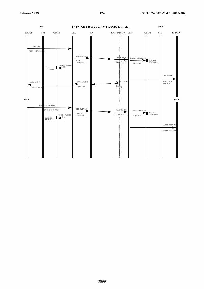
3GPP
3G TS 24.007 V3.4.0 (2000-06)124Release 1999
MS NET
GMMSNDCP LLC RR SM SNDCPLLCRR BSSGPSM GMM
C.12 MO Data and MO-SMS transfer
LL-DATA-REQ
[TLLI, N-PDU, local ref. ]
LLGMM-TRIGGER-IND
[ TLLI, CI ]
RESTARTREADY-timer
LL-DATA-IND
[ N-PDU, TLLI, local ref. ]
LL-DATA-CNF
[TLLI, local ref.]
LLGMM-TRIGGER -IND
[ ]
RESTARTREADY-timer
SMS SMS
LL- UNITDATA-REQ
[TLLI, SMS-CP-PDU ]
RESTARTREADY-timer
LL-UNITDATA-IND
[ SMS-CP-PDU, TLLI ]
RESTARTREADY-timer
GRR-DATA--REQ
[LLC-RR, priority=data]
GRR-DATA-IND
[ LLC-I, TLLI, CI ]
GRR-DATA-IND
[ LLC-UI, TLLI, CI ]
GRR-DATA-IND
[ LLC-RR]
GRR-DATA-REQ
[ LLC-UI, SAPI=SMS ]
GRR-DATA-REQ
[ LLC-I, SAPI=data ]
LLGMM-TRIGGER -IND
[ ]
LLGMM-TRIGGER-IND
[ TLLI, CI ]

3GPP
3G TS 24.007 V3.4.0 (2000-06)125Release 1999
MS NET
GMM SNDCP LLC RR SM SNDCP LLC RR BSSGP SM GMM
C.13 Paging and MT Data transfer
LLGMM-TRIGGER -REQ
[ ] GRR-DATA-IND
[LLC PDU, TLLI, CI]
GMMRR-PAGE-REQ GMMRR-PAGE-IND
LL-DATA-REQ
[ N-PDU, TLLI, local ref. ]
[TLLI, IMSI, CI or CI-list or RAI, SAPI=signalling ]
LLGMM-PAGE-IND
[ TLLI ]
[ ]
RESTART READY-timer
READY-timer expires
LL-DATA-IND
[ TLLI, N-PDU, local ref. ]
RESTART READY-timer LLGMM-TRIGGER-IND
[ TLLI, CI] RESTART READY-timer
LL-DATA-CNF
[ TLLI, local ref. ]
Normal LLC traffic continues
START PAGING timer
STOP PAGING timer
LLGMM-SUSPEND-REQ
[ TLLI, cause ]
A LLC frame is sent, see �Cell update�, C17
RESTART READY-timer LLGMM-TRIGGER-
RESP-IND
[ TLLI, CI ]
GRR-DATA--REQ
[LLC-I, SAPI=data]
GRR-DATA-IND
[ LLC-RR, TLLI, CI ]
LLC is resumed, MM in READY
LLGMM-RESUME-REQ
[ TLLI ] GRR-DATA-IND
[ LLC-I]
GRR-DATA-REQ
[ LLC-PDU, SAPI=data ]
GRR-DATA-REQ
[ LLC-RR, SAPI=data ]
LLGMM-TRIGGER -IND
[ ]
LLC is suspended, MM in STANDBY, cause indicates that paging is required if data has to be sent
LL-DATASENT -IND
[ [TLLI, local ref., V(S)]

3GPP
3G TS 24.007 V3.4.0 (2000-06)126Release 1999
C.14 Paging for SMS and SMS-MT transferMS NET
GMMSMS LLC RR SM SMSLLCRR BSSGPSM GMM
LL-DATA-REQ
[SMS-CP-PDU, TLLI ]
LLGMM-PAGE-IND
READY-timerexpires
LLC is suspended,MM in STANDBY,cause indicates that paging is required if data has to be sent
LLGMM-SUSPEND-REQ
[ TLLI, cause ]
[ TLLI ]
LLGMM-TRIGGER-REQ
[ ] GRR-DATA-IND
[LLC PDU, TLLI,CI]
GMMRR-PAGE-REQGMMRR-PAGE-IND
[TLLI, IMSI, CI or CI-list or RAI, SAPI=signalling ]
[ ]
RESTARTREADY-timer
LL-DATA-IND
[ TLLI, SMS-CP--PDU]
Normal LLC traffic continues
START PAGINGtimer
STOP PAGINGtimer
An LLC frameis sent, see �Cellupdating� C17
RESTARTREADY-timer
LLGMM-TRIGGER-IND
[ TLLI, CI ]
GRR-DATA--REQ
[LLC-UI, SAPI=SMS]
LLC is resumed,MM in READY
LLGMM-RESUME-REQ
[ TLLI ]GRR-DATA-IND
[ LLC-UI]
GRR-DATA-REQ
[ LLC-PDU, SAPI=data/unitdata ]

3GPP
3G TS 24.007 V3.4.0 (2000-06)127Release 1999
MS NET
GMMSNDCP LLC RR SM SNDCPLLCRR BSSGPSM GMM
C.15 Generic Routing Area Update, Intra SGSN
STARTTrams
LL-UNITDATA-IND
[PDU= RA Update Req ( TLLI plus RAI), oldTLLI, CI ]
Security function may be invoked
LL-UNITDATA-REQ
[ PDU= RA Update Req ( TLLI plus old RAI),Cipher=off ]
STOPTrams
LL-UNITDATA-REQ
[PDU=RA Update- Accept (newTLLI) ]
LL-UNITDATA-IND
[PDU=RA Update- Accept (newTLLI) ]
LLGMM-ASSIGN-REQ
[ newTLLI ]
[PDU-RA Update Compl, newTLLI, CI ]
LL_UNITDATA_IND
Stop Tran
LLGMM-ASSIGN-REQ
[ Rx: newTLLI or oldTLLI Tx: newTLLI ]
GMMRR-ASSIGN-REQ
[ new TLLI ]
Start Tran
LLGMM-ASSIGN-REQ
[ unassign oldTLLI ]
LLGMM-SUSPEND-REQ
[ ]
SMM-RESUME-REQ
[ ]
GRR-DATA-REQ
[ LLC-UI, SAPI=signalling ]
GRR-DATA-REQ
[ LLC-PDU, SAPI=signalling ]
GRR-DATA-IND
[ LLC-UI]
GRR-DATA-IND
[LLC UI, old TLLI, CI]
GRR-DATA-IND
[LLC PDU new TLLI, CI]
LL-UNITDATA-REQ
[ PDU=RA Update- Compl,Cipher=on ]
GRR-DATA--REQ
[LLC-UI, SAPI=signalling ]
The oldTLLI may be a LocalTLLI, or a Foreign TLLI, or aRandom TLLI
LLGMM-ASSIGN-REQ
[ unassign oldTLLI ]
GMMRR-ASSIGN-REQ
[ unassign oldTLLI ]
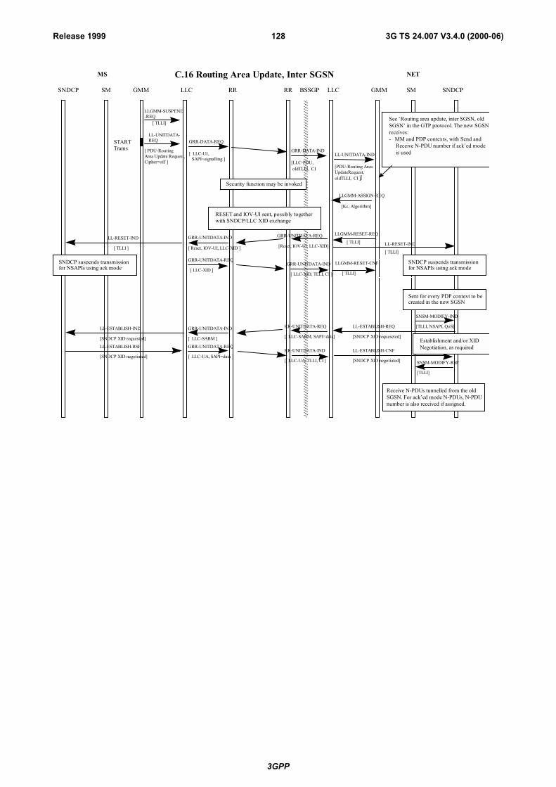
3GPP
3G TS 24.007 V3.4.0 (2000-06)128Release 1999
MS NET
GMMSNDCP LLC RR SM SNDCPLLCRR BSSGPSM GMM
C.16 Routing Area Update, Inter SGSN
GRR-DATA-IND
[LLC-PDU, oldTLLI, CI
LL-UNITDATA-IND
[PDU-Routing AreaUpdateRequest,oldTLLI, CI ]]
Security function may be invoked
[ PDU= Kc, Algorith ]
GRR-DATA-REQ
[ LLC-UI,SAPI=signalling ]
STARTTrams
LL-UNITDATA-REQ
[ PDU-RoutingArea Update Request,Cipher=off ]
LLGMM-SUSPEND-REQ
[ TLLI]See �Routing area update, inter SGSN, oldSGSN� in the GTP protocol. The new SGSNreceives:
Receive N-PDU number if ack�ed mode is used
- MM and PDP contexts, with Send and
[Kc, Algorithm]
LLGMM-ASSIGN-REQ
RESET and IOV-UI sent, possibly togetherwith SNDCP/LLC XID exchange
RR-UNITDATA-REQ
RR-UNITDATA-IND
[ LLC-SABM, SAPI=data]
[ LLC-UA, TLLI, CI ]
LL-ESTABLISH-IND
LL-ESTABLISH-RSP
[SNDCP XID requested]
[SNDCP XID negotiated]
GRR-UNITDATA-IND
GRR-UNITDATA-REQ
[ LLC-SABM ]
[ LLC-UA, SAPI=data ]
LL-ESTABLISH-REQ
LL-ESTABLISH-CNF
SNSM-MODIFY-RSP
[SNDCP XID requeseted]
[SNDCP XID negotiated]
SNSM-MODIFY-IND
[TLLI, NSAPI, QoS]
[TLLI]
Establishment and/or XIDNegotiation, as required
Receive N-PDUs tunnelled from the oldSGSN. For ack�ed mode N-PDUs, N-PDUnumber is also received if assigned.
GRR-UNITDATA-REQ
[Reset, IOV-UI, LLC-XID]
GRR-UNITDATA-IND
[ LLC-XID, TLLI, CI ]
LLGMM-RESET-REQ
[ TLLI]
[ TLLI]
LL-RESET-IND[ TLLI]
LLGMM-RESET-CNF
[ TLLI ]
GRR-UNITDATA-IND
[ Reset, IOV-UI, LLC-XID ]
GRR-UNITDATA-REQ
[ LLC-XID ]
LL-RESET-IND
SNDCP suspends transmissionfor NSAPIs using ack mode
SNDCP suspends transmissionfor NSAPIs using ack mode
Sent for every PDP context to becreated in the new SGSN
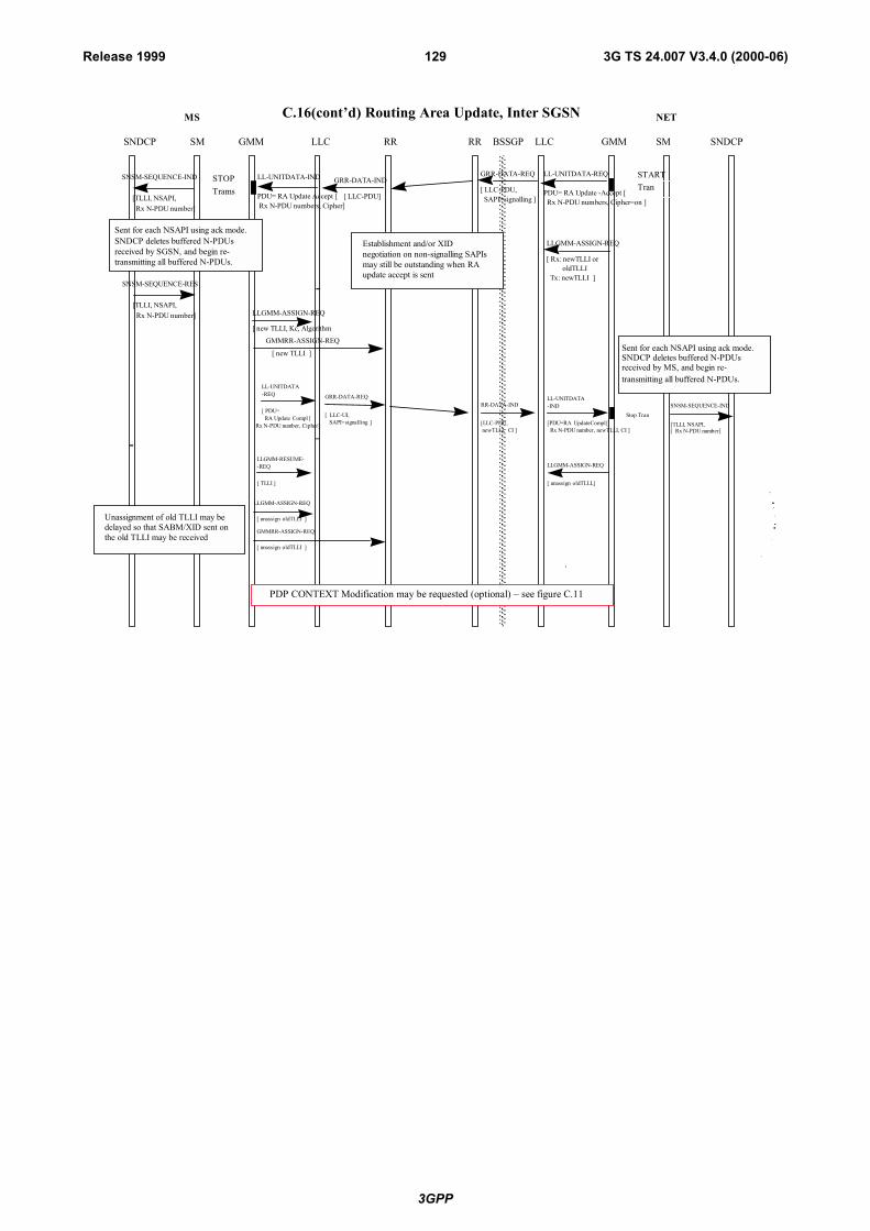
3GPP
3G TS 24.007 V3.4.0 (2000-06)129Release 1999
MS NET
GMMSNDCP LLC RR SM SNDCPLLCRR BSSGPSM GMM
PDP CONTEXT Modification may be requested (optional) � see figure C.11
[ oldTLLI ]
[
LLGMM-ASSIGN-REQ
unassign
GMMRR-ASSIGN-REQ
unassign oldTLLI ]
Unassignment of old TLLI may bedelayed so that SABM/XID sent onthe old TLLI may be received
C.16(cont�d) Routing Area Update, Inter SGSN
RR-DATA-IND
[LLC-PDU,newTLLI, CI ]
[
LLGMM-ASSIGN-REQ
unassign oldTLLI,]
GRR-DATA-REQ
[ LLC-UI,SAPI=signalling ]
[[ PDU= RA Update Compl
Rx N-PDU number, Cipher]
LL-UNITDATA-REQ
[ TLLI ]
LLGMM-RESUME--REQ
[PDU=RA UpdateCompl [ Rx N-PDU number, newTLLI, CI ]
LL-UNITDATA-IND
Stop TranSNSM-SEQUENCE-IND
[TLLI, NSAPI,[ Rx N-PDU number]
Sent for each NSAPI using ack mode.SNDCP deletes buffered N-PDUsreceived by MS, and begin re-transmitting all buffered N-PDUs.
GRR-DATA-REQ
[ LLC-PDU, SAPI=signalling ]
LLGMM-ASSIGN-REQ
[ Rx: newTLLI or oldTLLI Tx: newTLLI ]
GMMRR-ASSIGN-REQ
[ new TLLI ]
LLGMM-ASSIGN-REQ
[ new TLLI, Kc, Algorithm
GRR-DATA-IND
[ LLC-PDU]
LL-UNITDATA-REQ
PDU= RA Update -Accept [ Rx N-PDU numbers, Cipher=on ]
STARTTran
Establishment and/or XIDnegotiation on non-signalling SAPIsmay still be outstanding when RAupdate accept is sent
STOPTrams
SNSM-SEQUENCE-IND
[TLLI, NSAPI, Rx N-PDU number]
Sent for each NSAPI using ack mode.SNDCP deletes buffered N-PDUsreceived by SGSN, and begin re-transmitting all buffered N-PDUs.
LL-UNITDATA-IND
PDU= RA Update Accept [ Rx N-PDU numbers, Cipher]
SNSM-SEQUENCE-RES
[TLLI, NSAPI, Rx N-PDU number]
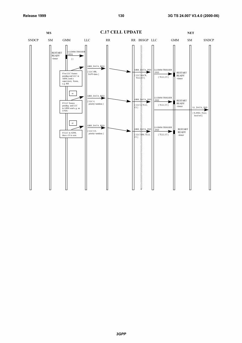
3GPP
3G TS 24.007 V3.4.0 (2000-06)130Release 1999
MS NET
GMMSNDCP LLC RR SM SNDCPLLCRR BSSGPSM GMM
LLGMM-TRIGGER-REQ
[ ]
GRR_DATA_REQ
[ LLC-RR, SAPI=data ]
GRR_DATA_IND
[ LLC-SACK, TLLI, CI ]
LLGMM-TRIGGER-IND
[ TLLI, CI ]
C.17 CELL UPDATE
GRR_DATA_REQ
[ LLC-I, priority=unitdata ]
GRR_DATA_IND
[ LLC-I, TLLI,CI ]
[ N-PDU, TLLI, local ref.]
LL_DATA_IND
If no LLC framespending and LLC inABM, send asupervisory frame,e.g. RR
If LLC framespending and LLCin ABM send e.g. anI PDU
RESTARTREADY-timer
RESTARTREADY-timer
or
LLGMM-TRIGGER-IND
[ TLLI, CI ]
RESTARTREADY-timer
GRR_DATA_REQ
[ LLC-UI, priority=unitdata ]
GRR_DATA_IND
[ LLC-DM, TLLI,CI ]
If LLC in ADM,then a UI is sent.
or
LLGMM-TRIGGER-IND
[ TLLI, CI ]
RESTARTREADY-timer
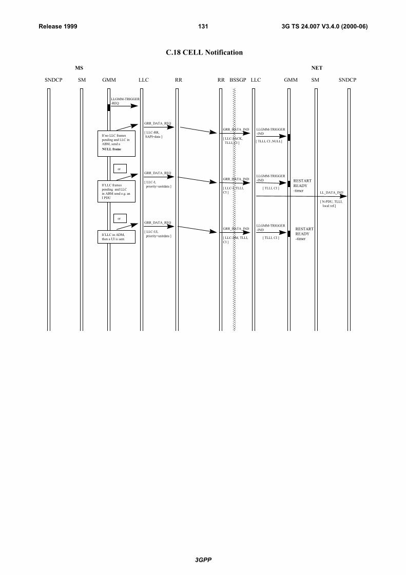
3GPP
3G TS 24.007 V3.4.0 (2000-06)131Release 1999
MS NET
GMMSNDCP LLC RR SM SNDCPLLCRR BSSGPSM GMM
LLGMM-TRIGGER-REQ
GRR_DATA_REQ
[ LLC-RR, SAPI=data ]
GRR_DATA_IND
[ LLC-SACK, TLLI, CI ]
LLGMM-TRIGGER-IND
[ TLLI, CI ,NULL]
C.18 CELL Notification
GRR_DATA_REQ
[ LLC-I, priority=unitdata ]
GRR_DATA_IND
[ LLC-I, TLLI,CI ]
[ N-PDU, TLLI, local ref.]
LL_DATA_IND
If no LLC framespending and LLC inABM, send aNULL frame
If LLC framespending and LLCin ABM send e.g. anI PDU
or
LLGMM-TRIGGER-IND
[ TLLI, CI ]
RESTARTREADY-timer
GRR_DATA_REQ
[ LLC-UI, priority=unitdata ]
GRR_DATA_IND
[ LLC-DM, TLLI,CI ]
If LLC in ADM,then a UI is sent.
or
LLGMM-TRIGGER-IND
[ TLLI, CI ]
RESTARTREADY-timer
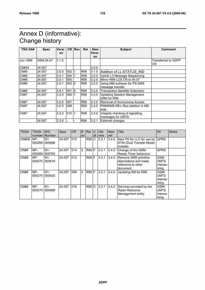
3GPP
3G TS 24.007 V3.4.0 (2000-06)132Release 1999
Annex D (informative):Change historyTSG SA# Spec Versi
onCR Rev Rel New
Version
Subject Comment
Jun 1999 GSM 04.07 7.1.0 Transferred to 3GPPCN
CN#04 24.007 3.0.0CN#5 24.007 3.0.0 002 1 R99 3.1.0 Addition of LL-STATUS_INDCN#6 24.007 3.0.1 004 1 R99 3.2.0 Uplink L3 Message SequencingCN#6 24.007 3.0.1 005 R99 3.2.0 Mirror R99 LCS CR to 04.07CN#6 24.007 3.0.1 003 5 R99 3.2.0 Using MM sublayer for PS-SMS
message transferCN#6 24.007 3.0.1 001 5 R99 3.2.0 Transaction Identifier ExtensionCN#7 24.007 3.2.0 006 1 R99 3.3.0 Updating Session Management
(SM) for R99CN#7 24.007 3.2.0 007 R99 3.3.0 Removal of Anonymous AccessCN#7 24.007 3.2.0 008 R99 3.3.0 PMMSMS-REL-Req deletion in MS
sideCN#7 24.007 3.2.0 010 1 R99 3.3.0 Integrity checking of signalling
messages for UMTS- 24.007 3.3.0 - - R99 3.3.1 Editorial changes
TSGN TSGN-number
WGNumber
Spec CR Rev
Rel Cat
Oldvers
Newver
Title WI Notes
CN#08 NP-000269
N1-000668
24.007 015 R99 C 3.3.1 3.4.0 New PD for LLC for use byDTM (Dual Transfer Mode)mobiles
GPRS
CN#8 NP-000269
N1-000763
24.007 014 2 R99 F 3.3.1 3.4.0 Change of the GMMReady Timer behaviour
GPRS
CN#8 NP-000270
N1-000619
24.007 012 R99 F 3.3.1 3.4.0 Remove GRR primitivedescriptions and makereference to otherdocument
GSM -UMTSInterworking
CN#8 NP-000270
N1-000620
24.007 006 2 R99 F 3.3.1 3.4.0 Updating SM for R99 GSM/UMTSInterworking
CN#8 NP-000270
N1-000669
24.007 016 R99 C 3.3.1 3.4.0 Services provided by theRadio ResourceManagement entity
GSM/UMTSInterworking


![TS-3GA-25.415(R99)v3.12.0 UTRAN Iu interface user plane ... · UTRAN Iu interface user plane protocols ... "UTRAN Iu Interface Data Transport and Transport Signalling". [5] 3GPP TS](https://img.pdfslide.us/doc/110x75/5b4d0f027f8b9ac6118bb2ed/ts-3ga-25415r99v3120-utran-iu-interface-user-plane-utran-iu-interface.jpg)