Embed Size (px)
Citation preview
The Zurich Urban Micro Aerial VehicleDataset
Journal TitleXX(X):1–5c©The Author(s) 2016
Reprints and permission:sagepub.co.uk/journalsPermissions.navDOI: 10.1177/ToBeAssignedwww.sagepub.com/
Andras L. Majdik1 Charles Till2 and Davide Scaramuzza2
AbstractThis paper presents a dataset recorded on-board a camera-equipped Micro Aerial Vehicle (MAV) flying within theurban streets of Zurich, Switzerland, at low altitudes (i.e., 5-15 meters above the ground). The 2 km dataset consistsof time synchronized aerial high-resolution images, GPS and IMU sensor data, ground-level street view images, andground truth data. The dataset is ideal to evaluate and benchmark appearance-based localization, monocular visualodometry, simultaneous localization and mapping (SLAM), and online 3D reconstruction algorithms for MAVs in urbanenvironments.
Keywordsvisual localization, air-ground matching, aerial robotics
Supplementary materialThe dataset is available at:http://rpg.ifi.uzh.ch/zurichmavdataset.html
IntroductionNew applications of Micro Aerial Vehicles (MAVs) areenvisioned by several companies, e.g., good delivery(e.g., Amazon Prime Air, DHL, Alibaba, Matternet,Swiss Post), inspection and monitoring (e.g., SenseFly,Skycatch), medications and blood samples transportation(e.g., Matternet, Flirtey, Wingtra, RedLine), first-responseand telepresence in case of accidents (e.g., Drone Aventures,Microdrones).
Accurate localization is indispensable and is a prerequisitefor the successful completion of these tasks in a real-lifeenvironment. For above-rooftop flight, even consumer-gradestandard and differential GPS receivers provide sufficientlyaccurate localization (less than 1 meter). However theaccuracy and reliability of GPS sensing fundamentallydepends on the number of visible satellites which are in theline of sight of the receiver. In urban areas, the availabilityof GPS signals is often reduced if compared to unobstructedterrain, or even completely unavailable in case of restrictedsky view. So-called urban canyons tend to shadow the GPSsignals, and building facades reflect the signals violatingthe underlying triangulation assumption that signals travelalong a direct line of sight between the satellite and thereceiver (i.e., multipath). Thus, in urban streets vision-basedlocalization and position estimation algorithms are needed.
Recently, the TorontoCity dataset was proposed in Wanget al. (2016) that consists of data captured from: (i)overhead perspective (images and airborne LIDAR capturedby airplanes and drones); (ii) ground perspective (street viewpanoramas, stereo images, Velodyne LIDAR, and GoProcaptured by cars); (iii) high-precision maps (buildings androads, 3D buildings, property meta-data). However, the
Aerial view
MAV path
GPS data
Street View
image locations
Figure 1. Bird-eye view of the urban test area. The red plussigns mark the locations of the ground Google Street Viewimages. The blue asterisks mark the GPS labels of the aerialMAV images measured on-board. The green dots represent theground truth path of the MAV.
1MTA SZTAKI, Institute for Computer Science and Control, HungarianAcademy of Sciences, Hungary2Department of Informatics, University of Zurich, Switzerland
Corresponding author:Andras L. Majdik, Machine Perception Research Laboratory, MTASZTAKI, Kende u. 13-17, 1111 Budapest, Hungary—http://www.sztaki.huCharles Till and Davide Scaramuzza, Robotics and Perception Group,University of Zurich, Andreasstrasse 15, 8050 Zurich, Switzerland—http://rpg.ifi.uzh.ch
Email: [email protected]; [email protected];[email protected]
Prepared using sagej.cls [Version: 2015/06/09 v1.01]
2 Journal Title XX(X)
Table 1. Dataset structure.
Folder/File name Description
./Log Files/ Folder containing on-board log files and ground truth data.--BarometricPressure.csv Log data of the on-board barometric pressure sensor.--OnbordGPS.csv Log data of the on-board GPS receiver.--OnboardPose.csv Log of the on-board Pixhawk PX4 autopilot pose estimation.--RawAccel.csv Log data of the on-board accelerometer.--RawGyro.csv Log data of the on-board gyroscope.--GroundTruthAGL.csv Ground truth MAV camera positions.--GroundTruthAGM.csv Ground truth matches of image IDs between the aerial and ground level images.--StreetViewGPS.csv GPS tags of the ground level Street View images.
./MAV Images/ Folder with 81’169 images recorded by the MAV in the city of Zurich, Switzerland.
./MAV Images Calib/ 30 images with calibration pattern to compute the intrinsic MAV camera parameters.
./Street View Img/ Folder with 113 Google Street View images covering the area of the data collection.
./calibration data.npz Internal camera parameters computed using the images from ./MAV Images Calib/
./loadGroundTruthAGL.m This script is used by plotPath.m to load the data into Matlab.
./plotPath.m Script to visualize the GPS and ground truth path in Matlab, similarly to Figure 3.
./write ros bag.py Script to write the data into a ROS—http://ros.org bag file.
./readme.txt More detailed descriptions about the files listed above.
TorontoCity benchmark contains only downwards facingimages captured at high altitudes and lacks aerial footagecaptured by MAVs flying at low altitudes within urbanstreets. A visual-inertial dataset was proposed in Burriet al. (2016) for autonomous navigation of MAVs inindoor industrial environments (i.e., large machine hall andVicon room). Conversely, the proposed dataset is meant tobenchmark algorithms in outdoor environments and includeaerial footage captured by a MAV flying at low altitudeswithin urban streets.
The dataset detailed in this paper is ideal to evaluateview-point invariant, image-based localization algorithmsfor GPS-denied MAVs, as we recently proposed in Majdiket al. (2015). In that paper, we described how to match low-altitute airborne images against Google Street View imagesto localize a quadrotor within urban streets. Furthermore, thedataset is a challenging benchmark to test visual odometry,SLAM, and online 3D reconstruction algorithms for MAVnavigation in urban environments.
The 2 km dataset was recorded in January 2015 with aFotokite∗ quadrotor equipped with a GoPro Hero 4 camera,flying in a downtown area of Zurich at low altitudes (i.e., 5-15 meters above the ground). The Fotokite is a tethered MAVthat enables aerial filming in confined environments, suchas cluttered city streets with GPS signals that suffer frominaccuracy. The tether is connected to the user, who controlsthe 3D position of the drone either by maneuvering the tetheror through a smartphone interface. The smartphone interfacealso allows the user to further change the yaw angle of thedrone and the pitch angle of the camera. Battery power isprovided through the tether for up to 45 minutes of non-stopflight. The tether also renders the Fotokite drone safe andlegal for data collection in urban streets. All these advantagesmake the Fotokite drone the ideal platform to record ourdataset.
The bird-eye view of the urban test area is shown inFigure 1. To record the dataset, the flying vehicle waspiloted close to the center of the streets and the MAVcamera was always kept facing the buildings. In Figure 1the trajectory estimated by the on-board GPS is marked inblue. The red plus signs mark the locations of the ground
Google Street View images. In order to estimate the actualtrajectory of the MAV (marked in green) we performedan accurate photogrammetric 3D reconstruction using thePix4D† software, c.f. Figure 5. Note that the GPS signalwas shadowed by the surrounding buildings, therefore a root-mean-square geo-location error of 2.22 meters in X, 3.76meters in Y, and 5.46 meters in Z, exists relative to the actualpath of the MAV.
Dataset formatThe dataset contains time-synchronized high-resolutionimages (1920 x 1080 x 24 bits), GPS, IMU, and ground-level Google-Street-View images. The high-resolution aerialimages were captured with a rolling shutter GoPro Hero 4camera that records each image frame line by line, from topto bottom with a readout time of 30 millisecond. A summaryof the enclosed files is given in Table 1.
The data from the on-board barometric pressure sen-sor BarometricPressure.csv, accelerometer RawAccel.csv,gyroscope RawGyro.csv, GPS receiver OnbordGPS.csv,and pose estimation OnboardPose.csv is logged and time-synchronized using the clock of the PX4 autopilot board. Theon-board sensor data was spatially and temporally alignedwith the aerial images. The delta time period was set onlyonce at the beginning of the recording and was not changedfor every individual image. Its spatio-temporal accuracy waschecked by examining fixed and well-identifiable pointsalong the Fotokites path. This was done by comparing themotion from the images with respect to the GPS and IMUmeasurements. The frame rate of 30Hz of the images com-bined with the slow and stable speed, at which the tetheredFotokite moves, made it possible to achieve a high spatio-temporal accuracy in the alignment of the images and theGPS/IMU measurements.
The first column of every file contains the timestamp whenthe data was recorded expressed in microseconds. In the nextcolumns the sensor readings are stored. The second column
∗Fotokite MAV: http://fotokite.com†Pix4D image processing software: https://pix4d.com/
Prepared using sagej.cls
Majdik, Till, and Scaramuzza 3
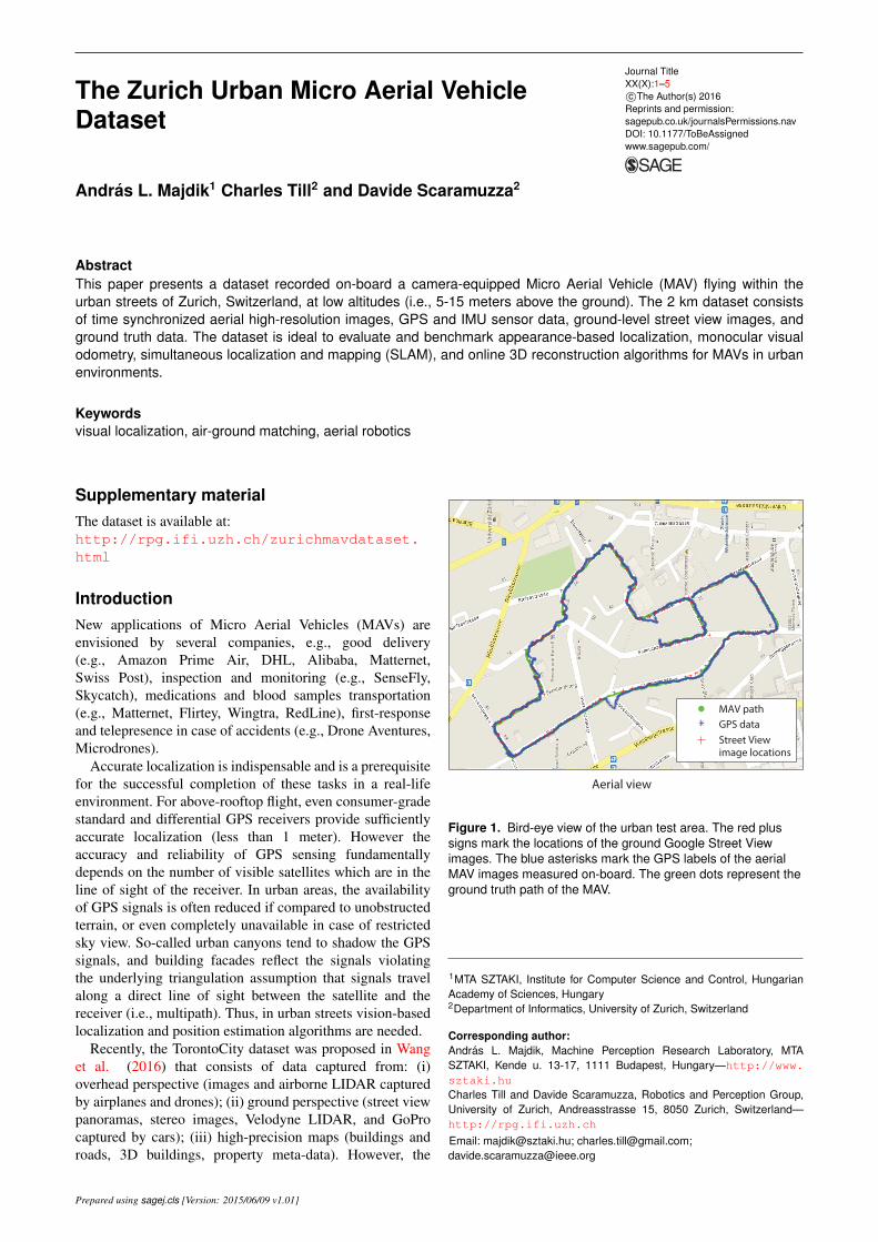
Figure 2. Different sensor coordinate systems used to recordthe data.
in OnbordGPS.csv encodes the identification number (ID)of every aerial image stored in the /MAV Images/ folder.The first column in GroundTruthAGL.csv is the ID of theaerial image, followed by the ground truth camera positionof the MAV and the raw GPS data. The second columnin GroundTruthAGM.csv is the ID of of the aerial image,followed by the ID of the first, second and third best matchground-level street view image in the /Street View Img/folder.
The coordinate frame conventions used to record the dataare shown in Figure 2. The translation between the bodyframe coordinate system (blue on Figure 2) to the cameraframe coordinate system (green on Figure 2) expressed inmillimeters is: 75.66 mm x-axis (forward); 29.68 mm y-axis(left of center); -32.27 mm z-axis (below the top face ofthe PX4 PCB). The on-board GPS data OnbordGPS.csv andthe GPS tags of the Street View images StreetViewGPS.csvuse the international WGS 84 (GPS) coordinate system. Theground truth MAV camera positions GroundTruthAGL.csvare in the International WGS 84 / UTM zone 32N coordinatesystem. Next, we present tools that can be used by the readerto index the data programmatically.
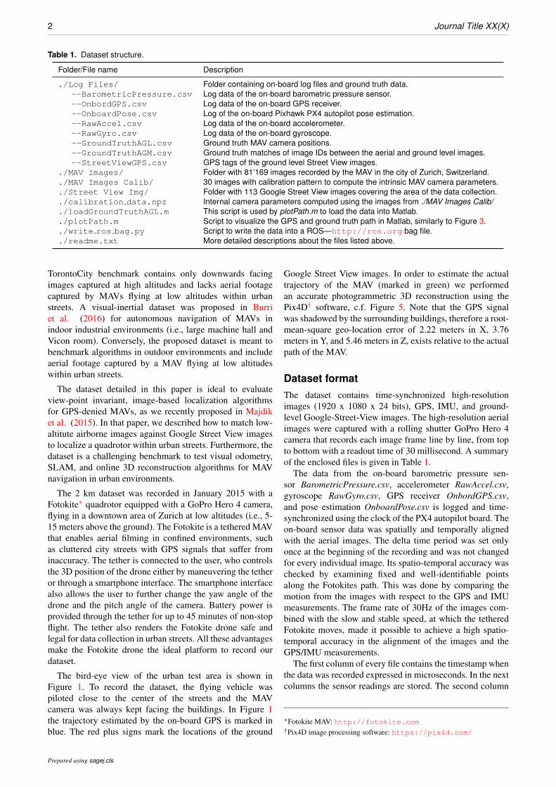
Parsing and indexingBeside the raw data measured during the flight, we providea script to visualize the ground truth path of the Fotokitein comparison with the recorded GPS location data inMATLAB, c.f. Figure 3. Also, we provide a script to parseand write all the data into a rosbag file in order to be easilyviewed and replayed using the ROS ecosystem. The loggednumerical data is saved in human readable tables, the highquality images have jpeg format.
CalibrationIn order to compute the intrinsic parameters of the on-boardcamera, we used a calibration checkerboard with knowndimensions. The size of the calibration checkerboard isnine squares wide and seven high, whereas the length ofa single side of one square is 2,45 cm. To compute theenclosed camera parameters we used the pinhole cameramodel and the calibration tools from the OpenCV library‡.
Figure 3. Comparison of the estimated GPS (red) and groundtruth (blue) trajectories.
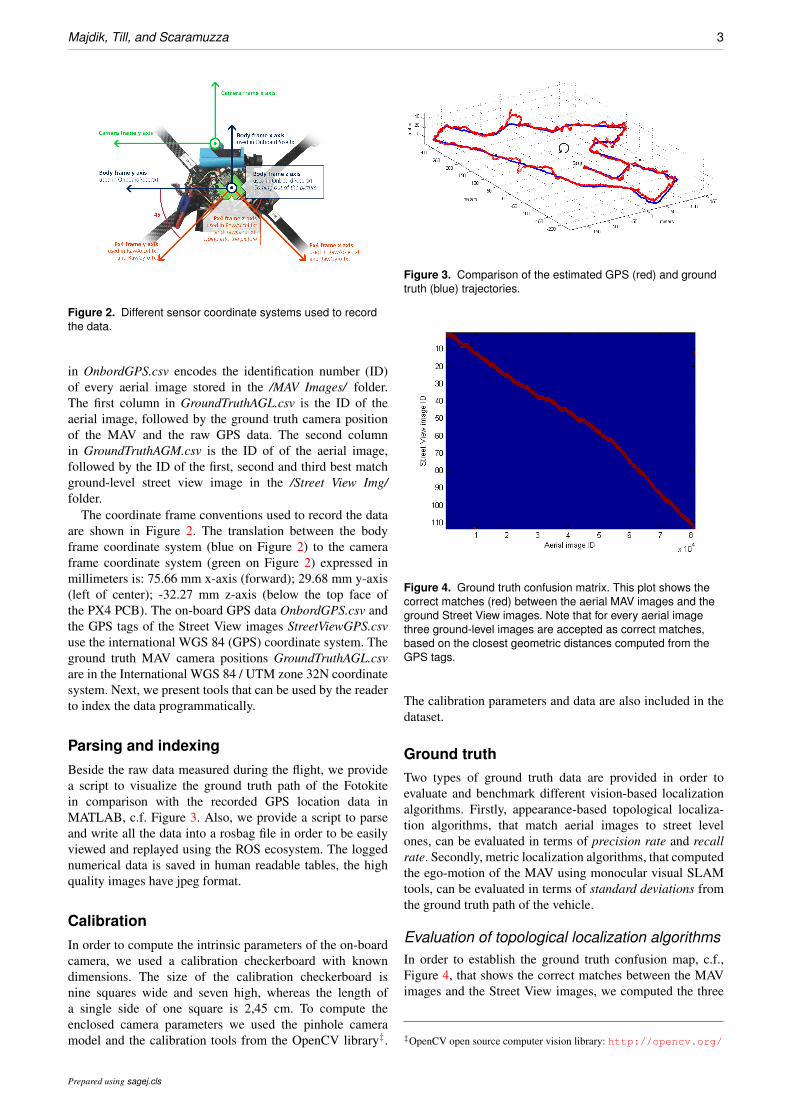
Figure 4. Ground truth confusion matrix. This plot shows thecorrect matches (red) between the aerial MAV images and theground Street View images. Note that for every aerial imagethree ground-level images are accepted as correct matches,based on the closest geometric distances computed from theGPS tags.
The calibration parameters and data are also included in thedataset.
Ground truthTwo types of ground truth data are provided in order toevaluate and benchmark different vision-based localizationalgorithms. Firstly, appearance-based topological localiza-tion algorithms, that match aerial images to street levelones, can be evaluated in terms of precision rate and recallrate. Secondly, metric localization algorithms, that computedthe ego-motion of the MAV using monocular visual SLAMtools, can be evaluated in terms of standard deviations fromthe ground truth path of the vehicle.
Evaluation of topological localization algorithmsIn order to establish the ground truth confusion map, c.f.,Figure 4, that shows the correct matches between the MAVimages and the Street View images, we computed the three
‡OpenCV open source computer vision library: http://opencv.org/
Prepared using sagej.cls
4 Journal Title XX(X)
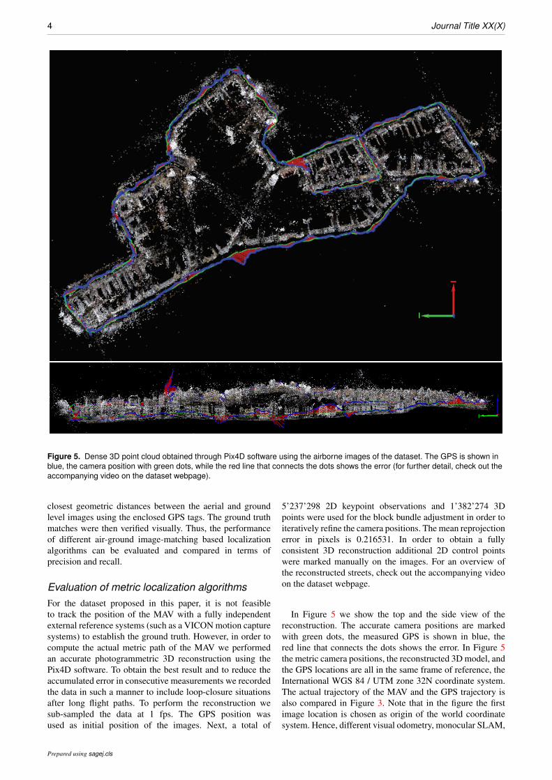
Figure 5. Dense 3D point cloud obtained through Pix4D software using the airborne images of the dataset. The GPS is shown inblue, the camera position with green dots, while the red line that connects the dots shows the error (for further detail, check out theaccompanying video on the dataset webpage).
closest geometric distances between the aerial and groundlevel images using the enclosed GPS tags. The ground truthmatches were then verified visually. Thus, the performanceof different air-ground image-matching based localizationalgorithms can be evaluated and compared in terms ofprecision and recall.
Evaluation of metric localization algorithmsFor the dataset proposed in this paper, it is not feasibleto track the position of the MAV with a fully independentexternal reference systems (such as a VICON motion capturesystems) to establish the ground truth. However, in order tocompute the actual metric path of the MAV we performedan accurate photogrammetric 3D reconstruction using thePix4D software. To obtain the best result and to reduce theaccumulated error in consecutive measurements we recordedthe data in such a manner to include loop-closure situationsafter long flight paths. To perform the reconstruction wesub-sampled the data at 1 fps. The GPS position wasused as initial position of the images. Next, a total of
5’237’298 2D keypoint observations and 1’382’274 3Dpoints were used for the block bundle adjustment in order toiteratively refine the camera positions. The mean reprojectionerror in pixels is 0.216531. In order to obtain a fullyconsistent 3D reconstruction additional 2D control pointswere marked manually on the images. For an overview ofthe reconstructed streets, check out the accompanying videoon the dataset webpage.
In Figure 5 we show the top and the side view of thereconstruction. The accurate camera positions are markedwith green dots, the measured GPS is shown in blue, thered line that connects the dots shows the error. In Figure 5the metric camera positions, the reconstructed 3D model, andthe GPS locations are all in the same frame of reference, theInternational WGS 84 / UTM zone 32N coordinate system.The actual trajectory of the MAV and the GPS trajectory isalso compared in Figure 3. Note that in the figure the firstimage location is chosen as origin of the world coordinatesystem. Hence, different visual odometry, monocular SLAM,
Prepared using sagej.cls
Majdik, Till, and Scaramuzza 5
and online 3D reconstruction algorithms can be evaluated interms of standard deviations using the proposed dataset.
Acknowledgements
This dataset was recorded with the help of Karl Schwabe, MathieuNoirot-Cosson, Yves Albers-Schoenberg and the Zurich police. Torecord the dataset we used a Fotokite MAV offered to our disposalby Perspective Robotics AG—http://fotokite.com.
The data recording was done in compliance with the Zurichcantonal law§, upon approval of the Zurich police.
Funding
This work was supported by the National Centre of Competencein Research Robotics (NCCR) through the Swiss National ScienceFoundation and by the Hungarian Scientific Research Fund (No.OTKA/NKFIH 120499).
References
Wang S, Bai M, Mattyus G, Chu H, Luo W, Yang B,Liang J, Cheverie J, Fidler S,Urtasun R (2016) TorontoCity:Seeing the World with a Million Eyes, December 2016.arXiv:1612.00423 [cs.CV].
Burri M, Nikolic J, Gohl P, Schneider T, Rehder J, Omari S,Achtelik M, Siegwart R (2016) The EuRoC micro aerial vehicledatasets, The International Journal of Robotics Research,Volume 35, Issue 10, pages 11571163, January 2016. DOI:10.1177/0278364915620033 SAGE Publications.
Majdik A, Verda D, Albers-Schoenberg Y and Scaramuzza D(2015) Air-ground Matching: Appearance-based GPS-deniedUrban Localization of Micro Aerial Vehicles, Journal of FieldRobotics, Volume 32, Issue 7, pages 10151039, October 2015.DOI: 10.1002/rob.21585 Wiley Periodicals, Inc.
§DETEC Ordinance on Special Category Aircraft, 24th November 1994,Sec. 7, and Regulation of the operation of model aircraft on public groundby the Stadtpolizei of Zurich, 8th July 1983, Nr. 651/82, Sec. 1
Prepared using sagej.cls