Embed Size (px)
Citation preview
Research Article Open Access
Volume 1 • Issue 3 • 1000107J Membra Sci TechnolISSN:2155-9589 JMST an open access journal
Open AccessResearch Article
Abdel-Hady et al. J Membra Sci Technol 2011, 1:3 DOI: 10.4172/2155-9589.1000107
Keywords: Gamma irradiation; PTFE membrane; grafting, styrene;phosphoration; sulfonation; TGA; Ac conductivity.
IntroductionDirect methanol fuel cells (DMFCs) have good potentialities for
applications as power sources in portable and mobile devices due to their high power density and low emission. In essence, a DMFC consists of an anode to which methanol aqueous solution is directly supplied, a cathode to which oxygen is supplied, and a polymer electrolyte membrane that prevents mixing of the methanol and oxygen and permits the proton transportation from anode to cathode [1].
The development of cost-effective and functional materials and components for the polymer electrolyte fuel cell (PEFC) is an important stepping stone towards the commercialization and market introduction of this technology [2-13]. In addition to the noble metal catalyst, the proton exchange membrane (PEM) material is a major contributor to the cost of the membrane electrode assembly (MEA). The state-of-the-art technology is mostly based on perfluorinated membrane materials, such as Nafion® (DuPont, USA), FlemionR (Asahi Glass, Japan) and Aciplex® (Asahi Kasei, Japan), and composites made thereof, such as the membrane made by W.L. GORE and associates. These materials are expensive due to the complex fluorine chemistry involved in the fabrication. The current price for Nafion® membranes is of the order of USD 100 per kilowatt generated electric power [14]. Today, commercially available DMFCs are based on Nafion® membranes or similar perfluorosulfonic membranes, which have excellent stability and high proton conduction. However, the use of methanol fuel with high concentration inevitably causes extensive degradation of performance because of drastic methanol crossover in those perfluorosulfonic membranes. This requires the extra auxiliary equipment to dilute methanol with water more than 10 times, forcing the decrease in energy density of the system. Therefore, many efforts have been devoted to the modification of Nafion® membranes and to the development of new polymer electrolyte membranes. For instance, modifications of Nafion® membranes by introduction of inorganic particles or by coating organic layers on their surfaces can control the methanol crossover to a certain extent [15,16]. The new membranes under development include sulfonated hydrocarbon membranes [17],
*Corresponding author: M.M. El-Toony, Ahmad El-Zomr Street, P.O. Box 29- Nasr City, Cairo, Egypt. 11370, Tel/ Fax: +202 22 944 803; E-mail: [email protected]
Received May 20, 2011; Accepted June 09, 2011; Published June 14, 2011
Citation: Abdel-Hady EE, Abdel-Hamed MO, El-Toony MM, El-Sharkawy MR (2011) Comparative Study between Sulfonation and Phosphoration for Commercial PTFE grafted with Styrene for Fuel Cell Application. J Membra Sci Technol 1:107. doi:10.4172/2155-9589.1000107
Copyright: © 2011 Abdel-Hady EE, et al. This is an open-access article distributed under the terms of the Creative Commons Attribution License, which permits unrestricted use, distribution, and reproduction in any medium, provided the original author and source are credited.
Comparative Study between Sulfonation and Phosphoration for Commercial PTFE grafted with Styrene for Fuel Cell Application E.E Abdel-Hady1, M.O. Abdel-Hamed1, M.M. El-Toony2* and M.R. El-Sharkawy1
1PhysicsDepartment, Faculty of Science, Menia University El-Menia City, Egypt 2National center for radiation research and technology, Atomic energy authority Egypt
hybrid membranes [18] and radiation-grafted membranes [19,20]. Currently, the current popular method for polymer electrolyte membrane fuel cells is to use a perfluorosulfonic acid copolymer produced by DuPont called Nafion® [21]. Although Nafion® has good chemical and physical properties for use in fuel cell applications, it has three technical limitations: its high cost, its low conductivity at low humidity or high temperature, and its high methanol permeability that reduces the cell efficiency [22].
The advantage of PBI/H3PO4 membranes, compared to Nafion®, is, that they are much cheaper than Nafion®. Their main disadvantage is that the H3PO4 molecules can diffuse out of the membrane because they are in excess towards basic polymer sites (six H3PO4 molecules per PBI repeating unit). Due to their high proton conductivity at T > 100oC these membranes are especially suitable for the application in direct methanol fuel cells (DMFC). Nafion® membranes are not that suitable for the application in direct methanol fuel cells, due to their high methanol permeability, which leads to strong potential reduction [23]. A disadvantage of the PBI/H3PO4 membranes with absorbed, not deposited H3PO4, is that they can only be used with a feed of vaporized methanol. When liquid contacts the membrane, the phosphoric acid leaches out of the membrane and the proton conductivity drops precipitously.
In these work grafting of styrene onto commercial PTFE was carried out via simultaneous gamma irradiation. Factors affecting grafting such as monomer concentration, irradiation dose and dose
AbstractSimultaneous gamma irradiation was used for grafting of styrene onto commercial PTFE films. Different
parameters affecting the grafting such as solvent, irradiation dose and monomer concentration were investigated. Sulfonation was performed using chlorosulfonic acid while phosphoric acid treatment was done in advance. Studying the role of phosphoric acid treatment for facilitating sulfonation of styrene grafting the PTFE membranes was carried out. FTIR spectroscopy and X-ray diffraction study confirmed the grafting and furthermore phosphoration and / or sulfonation. Scanning electron(SEM) was performed to characterize the morphological structure. Mechanical properties were discussed by measuring the hardness while chemical stability measurement assure their duration availability. Thermal characterization was investigated to proved the membrane applicability through wide range of temperature. Water uptake and ion exchange capacity were determined prior to measure the electrical conductivity and capacitance at different frequencies to assure the applicability of the grafted membranes in the fuel cell. Raising the temperature to 80°C increasing the Ec value to 1.08 x 10⁻¹ S/cm which is well comparable to that of Nafoin.
Journal of
Membrane Science & TechnologyJour
nal o
f Mem
brane Science & Technology
ISSN: 2155-9589
Citation: Abdel-Hady EE, Abdel-Hamed MO, El-Toony MM, El-Sharkawy MR (2011) Comparative Study between Sulfonation and Phosphoration for Commercial PTFE grafted with Styrene for Fuel Cell Application. J Membra Sci Technol 1:107. doi:10.4172/2155-9589.1000107
Page 2 of 9
Volume 1 • Issue 3 • 1000107J Membra Sci TechnolISSN:2155-9589 JMST an open access journal
rate were performed. Trials for phosphoric acid membrane treatment were investigated for proton conductivity. Comparing between sulfonation and phosphoric acid treatment were carried out for proton conductivity purpose. Sulfonation was furthermore done after phosphoric acid treatment to discuss availability this technique to be applied on fuel cell. Thermal, chemical, mechanical and morphological characterizations of the synthesized membrane were studied.
ExperimentalMaterials
Commercial polytetrafuoroethylene film with thickness 110µm was used, purchased from OPTCo, Egypt (Data shown as supplementary).
Styrene of purity 99.9% was supplied by Merck, Germany, other chemicals such as solvents, alkali acids ….etc., were reagent grade.
Polysulfone
Preparation of grafted membrane: The grafted PTFE membranes (PTFE-g-PST) were prepared using simultaneous irradiation method. PTFE film was cut into square pieces of known weight and size, washed with acetone and then dried in a vacuum oven at 60°C for 1 h. The clean film was placed into a glass ampoule and styrene monomer of known concentration diluted with dichloromethane. The styrene concentration was varied from 20 to100 vol.%. The grafting mixture was flushed with purified nitrogen for 8 min to remove the air and then the ampoule was tightly sealed. The ampoule was subjected to γ-rays from a 60°C source different dosed dose rate of 1.22 kGy/h. After the reaction is completed, the grafted film was removed, washed with toluene and soaked therein overnight to remove the residual monomer and the homopolymer occluded in the film surfaces. The grafted film was then dried in the vacuum oven at 80°C and weighed. The process of soaking and drying were repeated few times until a constant weight was obtained to ensure the complete removal of the homopolymer. The degree of grafting in PTFE-g-PST membranes was gravimetrically determined as the percentage of the weight increase of PTFE film using Eq. (1):
g o
oDegree of grafting% x 100
W WW−
= (1)
where Wg and Wo are the weights of grafted and un-grafted PTFE membranes, respectively. Grafting with two steps were carried out by repeating grafting by the same condition. Each step were performed via irradiation to 20 KGy, this technique was used to avoid reaching to the polymerization dose of styrene while increasing the free radials formation for PTFE film.
Sulfonation of grafted membrane: The sulfonation of phenyl group of styrene was carried out by soaking the grafted film in a mixture of chlorosulfonic acid and 1,2 dichloro ethane ratio 1:1 in ice bath for interval times (hours). The membranes were then washed with distilled water and dried in oven at 40oC [24].
Phosphoric acid treatments: It comprises that; γ-irradiation of water washed and dry grafted PTFE membranes in glass sealed ampoules. Diluted phosphoric acid with different solvents (methylene chloride and methanol) at 2.5, 5, 10% and 20% ratios were used. 5 KGy irradiation dose by 1.22 Gy/Sec. dose rate was applied for the grafted membranes treatment.
Swelling and porosity calculations
The liquid (water or methanol) sorption (S) of PSSA grafted
membranes was calculated using the following expression:
W D
Dx 100
m mS
m−
= (2)
Where mW is the mass of the swollen membrane and mD is the mass of the dry membrane. The porosity (ε) of PS PTFF (grafted) films was calculated via:
W D o
W D o D 2
( )( ) H O
m mm m m
ρε
ρ ρ−
=− +
(3)
where mW and mD are the weights of the water swollen and dry PS grafted PTFF films, respectively, ρH2O the water density, and ρo is the apparent density of the dried PS PTFF films that was calculated for each sample by taking into account the dimensional changes caused by PS grafting [25].
Ion exchange capacity (IEC)
The ion exchange capacity (meq/g) of the membranes was determined by acid–base titration technique. The dried membrane samples (3 cm×3 cm) in acid form were equilibrated in 50 ml of 0.05 M KCl overnight at room temperature with frequent stirring. The amount of proton (H+) released in the solution was then titrated to a cresol red endpoint with 0.05M KOH. After titration, the membrane samples were converted into acid form again by boiling with 3.5 M HCl for 3 h and washed free of acid. The membrane samples were then dried in vacuum oven (1.333224×10² Pa [1 Torr], 60°C) overnight. The dry weight of the membranes was determined after keeping it in a desiccator at ambient temperature over fresh silica gel for 30 min. The ion exchange capacity (IEC) of the dry membrane per unit mass (meq/g) was calculated from the following relationship:
KOHexperimental
dry
0.05IEC
Vm×
= (4)
where VKOH is the volume of KOH consumed and mdry the mass of the dried sample. The degree of sulfonation was defined as an ion exchange capacity (IEC) equivalent to one SO3H group per aromatic ring as reported by Walsby et al. [26]:
( ) experimental
theory
IECSulfonation yield % 100
IEC= × (5)
where IEC theory is the ion exchange capacity calculated from the grafting yield which was given by the following equation[26]:
theory9.62IEC
100 1.77Y
Y=
+ (6)
where Y is the grafting yield of the grafted film.
The equivalent weight (EW) was calculated from the following equation, which is reported as [27]
1000EWIEC
= (7)
Chemical stability
The chemical stability was characterized using a H2O2 aqueous solution [28]. For this purpose, the membrane with a size of 3 cm×3 cm was immersed in the 3% H2O2 aqueous solution at 60oC. During the immersion, the membranes were intermittently taken out of the solution and weighed after wiping off the excess surface water. The durability time, which was defined as the lasting time till the weight loss get started in the H2O2. The hardness can be measured as a function of time (120 minutes) to evaluate the availability of the membranes.
Citation: Abdel-Hady EE, Abdel-Hamed MO, El-Toony MM, El-Sharkawy MR (2011) Comparative Study between Sulfonation and Phosphoration for Commercial PTFE grafted with Styrene for Fuel Cell Application. J Membra Sci Technol 1:107. doi:10.4172/2155-9589.1000107
Page 3 of 9
Volume 1 • Issue 3 • 1000107J Membra Sci TechnolISSN:2155-9589 JMST an open access journal
Conductivity
Prior to conductivity measurements, the membranes were first transformed into protonic or acidic form. The proton conductivity of the membrane was measured with HIOKI LCR Hi-Tester, Model:3532, Japan by using a frequency range of 20 Hz–1 MHz. The impedance studies were conducted using temperature ranges from ambient to 80oC. The resistance (R) was obtained from the intercept of the impedance curve with real axis at high frequency end. The ionic conductivity (σ) was calculated according to the following equation:
1 1( cm ) LRA
σ − −Ω =
where L is the thickness of the membrane sample, A or (πr2) the sample surface area and R the resistance.
Scientific equipments
FTIR characterization: The functional groups of the grafted membrane were studied using Mattson 1000, Pye-Unicam, England.
Scan Electron Microscope (SEM)
Investigation and magnification of the grafted membrane surface was carried out by SEM, JEOL-JSM-5400, Japan.
X-ray diffraction
X-Ray diffraction spectra of PET and PET-g-PST membranes were obtained using a Philips PW 1830 X-ray diffractometer. The diffractograms were obtained at 2θ in the range of 5–60° using Cu K radiation (λ = 1.54A°) monochromated by means of a nickel filter.
Thermal gravimetric analysis
Shimadzu TGA -50, Japan, was used to characterize the thermal stability of the porous blend.
Hardness tester
Samples of were cut for 3 x 3 cm for hardness test. The measurement was carried out according to (ASTM D2240, 2000) by manual analogue instrument with pin produced termed Baxio, UK.The unit of hardness is expressed in (Shore A).
Gamma irradiation
Gamma irradiation was carried out by 60°C gamma rays with
a cylinder irradiation chamber. All irradiations were performed at ambient temperature (about 45oC at the chamber) and a dose rate of about 1.22 Gy/Sec.
Results and DiscussionsGrafting of styrene onto PTFE
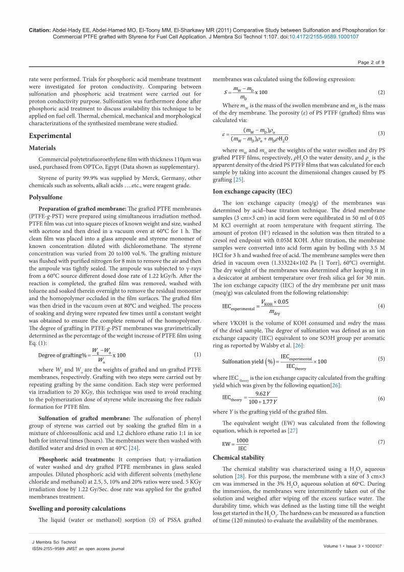
Effect of irradiation dose: The influence of absorbed dose on the degree of grafting of styrene on commercial PTFE was studied at a polymer/monomer ratio of 0.4. This ratio was the optimum ratio for the template polymerization of styrene onto PTFE. The results are shown in Figure (1) which showed that the grafting percent increases by increasing the irradiation dose. The acceleration of the copoly-merization of Sty on PTFE can be attributed to the gel effect and increasing viscosity of the system. In the gel state, as the polymerization of Sty increase, the viscosity of the medium is highly increased and the growing polymeric chains are trapped in the viscous medium [29-33]. The termination reaction by the mutual interaction of two growing chains become diffusion-controlled [35,36]. This increases the propagation reaction and retards the termination process. On the other hand, the units of active sites formed (free radicals) by increasing the irradiation dose [35,36]. The association between the monomer styrene and the polymer PTFE via hydrogen bonding in a polar solvent leads to the formation of plurim molecular aggregates [37-41]. In addition, the swelling of the polymer favors the monomer diffusion leading to increased monomer-polymer association. Hence, the probability of the copolymerization of the monomer is increased [32].
Monomer concentration
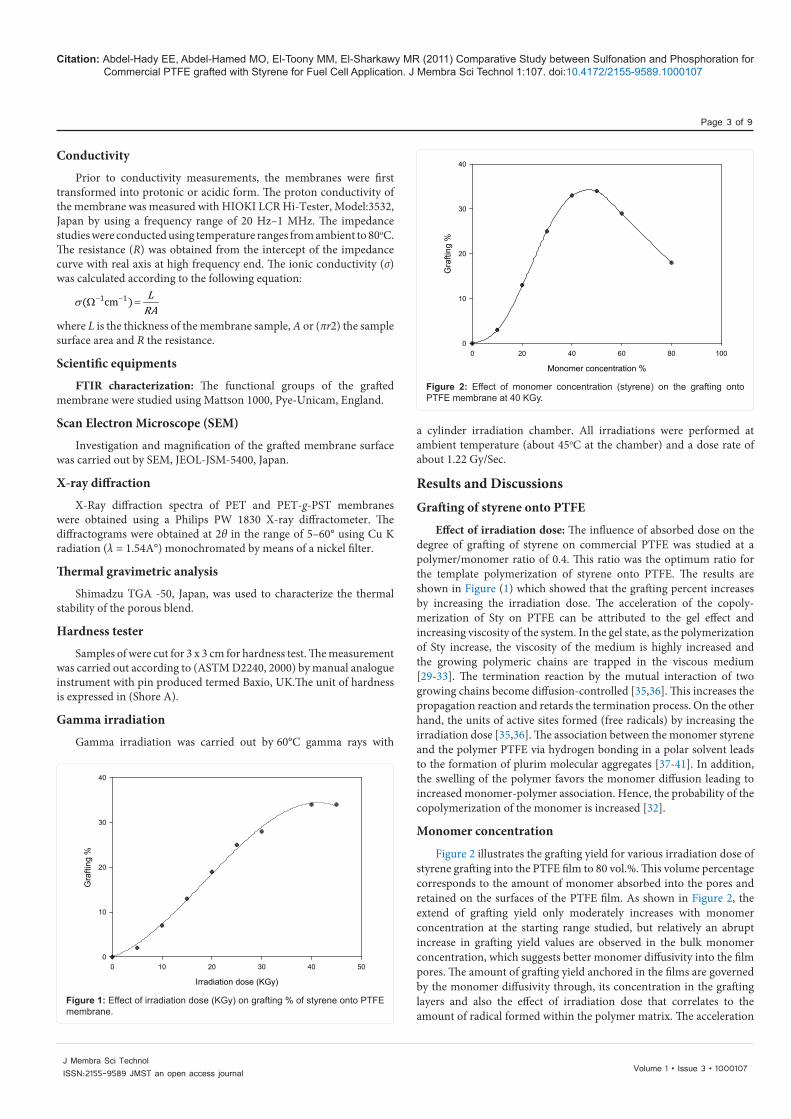
Figure 2 illustrates the grafting yield for various irradiation dose of styrene grafting into the PTFE film to 80 vol.%. This volume percentage corresponds to the amount of monomer absorbed into the pores and retained on the surfaces of the PTFE film. As shown in Figure 2, the extend of grafting yield only moderately increases with monomer concentration at the starting range studied, but relatively an abrupt increase in grafting yield values are observed in the bulk monomer concentration, which suggests better monomer diffusivity into the film pores. The amount of grafting yield anchored in the films are governed by the monomer diffusivity through, its concentration in the grafting layers and also the effect of irradiation dose that correlates to the amount of radical formed within the polymer matrix. The acceleration
Irradiation dose (KGy)
0 10 20 30 40 50
Gra
fting
%
0
10
20
30
40
Figure 1: Effect of irradiation dose (KGy) on grafting % of styrene onto PTFE membrane.
Monomer concentration %
0 20 40 60 80 100
Gra
fting
%
0
10
20
30
40
Figure 2: Effect of monomer concentration (styrene) on the grafting onto PTFE membrane at 40 KGy.
Citation: Abdel-Hady EE, Abdel-Hamed MO, El-Toony MM, El-Sharkawy MR (2011) Comparative Study between Sulfonation and Phosphoration for Commercial PTFE grafted with Styrene for Fuel Cell Application. J Membra Sci Technol 1:107. doi:10.4172/2155-9589.1000107
Page 4 of 9
Volume 1 • Issue 3 • 1000107J Membra Sci TechnolISSN:2155-9589 JMST an open access journal
of the grafting yield ranged 60-80% monomer concentration is assumed to be due to the decrease in the availability of the monomer to reach
each the radical sites which may due to highly viscous medium which reduce the free radicals speed while enfaces by the capability of the polymer backbone radical to capture the styrene radical that depends on the monomer concentration presence in its vicinity. Furthermore, higher irradiation dose results in the enhancement of the anchored polystyrene grafts into the interior of PTFE film. This finding is more or less in agreement with the results of Zhi-Li et al. [42], who studied the radiation graft copolymerization of vinylimidazole (VI) onto PTFE films.
Effect of solvent
These results can explained by taking the nature of the solvents and solubility of polystyrene homopolymer in styrene/solvents grafting solution into consideration. This was accompanied by complete solubility of styrene homopolymer, which might be formed in the grafting mixture. Therefore, swelling of the grafted layers and the styrene diffusion is enhanced and as a result longer polystyrene grafted branches are achieved.
Characterization of Grafted MembraneFTIR characterization
Table 3 showed a peak at 1797 cm-1 which is due to C-F stretching vibration, it have noticed also a peak at 1335 cm-1 which is as C=C. Sulfonation is confirmed as the appearance of wide peak extend from 1007 cm-1 to 1034 cm-1, first reading is due to mono substitution of sulfonic acid while second reading is due to di substitution. Expanding of such peak assure maximum sulfonation which reached to fully sulfonation for PTFE membrane. Poly phosphoric acid showed strong bands at 1040–910 cm−1 that belong to asymmetric stretching
(a)
(b)
(c)
(d)
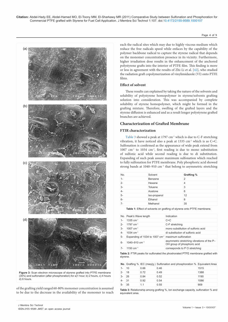
Figure 3: Scan electron microscope of styrene grafted into PTFE membrane (35%) and sulfonation (after phosphoration) for a)1 hour, b) 2 hours, c) 4 hours d) 6 hours.
No. Solvent Grafting %1- Benzene 22- Hexane 43- Toluene 34- Acetone 65- Iso-propanol 126- Ethanol 87- Methanol 35
Table 1: Effect of solvents on grafting of styrene onto PTFE membrane.
Table 2: FTIR peaks for sulfonated the phoshorated PTFE membrane grafted with styrene.
No. Peak's Wave length Indication1- 1335 cm-1 C=C2- 1797 cm-1 C-F stretching3- 1007 cm-1 mono substitution of sulfonic acid4- 1034 cm-1 di substitution of sulfonic acid5- Expanding of 1034 to 1007 cm-1 maximum sulfonation
6- 1040–910 cm−1 asymmetric stretching vibrations of the P–OH group of phosphoric acid
7- 1150 cm−1 corresponds to P O stretching
Table 3: Relationship among grafting %, Ion exchange capacity, sulfonation % and equivalent area.
No. Grafting % IEC (meq/g.) Sulfonation and phosphoration % Equivalent Area1- 10 0.66 0.46 15152- 18 0.72 0.49 13883- 26 0.84 0.52 11904- 31 0.92 0.54 10865- 35 1.1 0.55 909
Citation: Abdel-Hady EE, Abdel-Hamed MO, El-Toony MM, El-Sharkawy MR (2011) Comparative Study between Sulfonation and Phosphoration for Commercial PTFE grafted with Styrene for Fuel Cell Application. J Membra Sci Technol 1:107. doi:10.4172/2155-9589.1000107
Page 5 of 9
Volume 1 • Issue 3 • 1000107J Membra Sci TechnolISSN:2155-9589 JMST an open access journal
vibrations of the P–OH group and at 1150 cm−1 that corresponds to P=O stretching which proved the small extent of phosphoration of the membrane.
Scan electron microscope
Grafting percent and furthermore sulfonation affect severely morphological structure of the PTFE membrane morphology. Surface area increased with sulfonation time from 1 to 6 hours, grooves and channels could be seen while it widens as it seen in Figure 3a and 3b. further sulfonation conduct opening these channels in different positions leading to facilitation of ion transfers through the pores originates as complete sulfonation. Distribution of pores through the membranes surface area in more or less homogenous manners as seen in Figure (3c). Degradation of the membrane is noticed through different zones through the membrane in figure d while leading to maximum surface area is seen as well.
X-ray diffraction
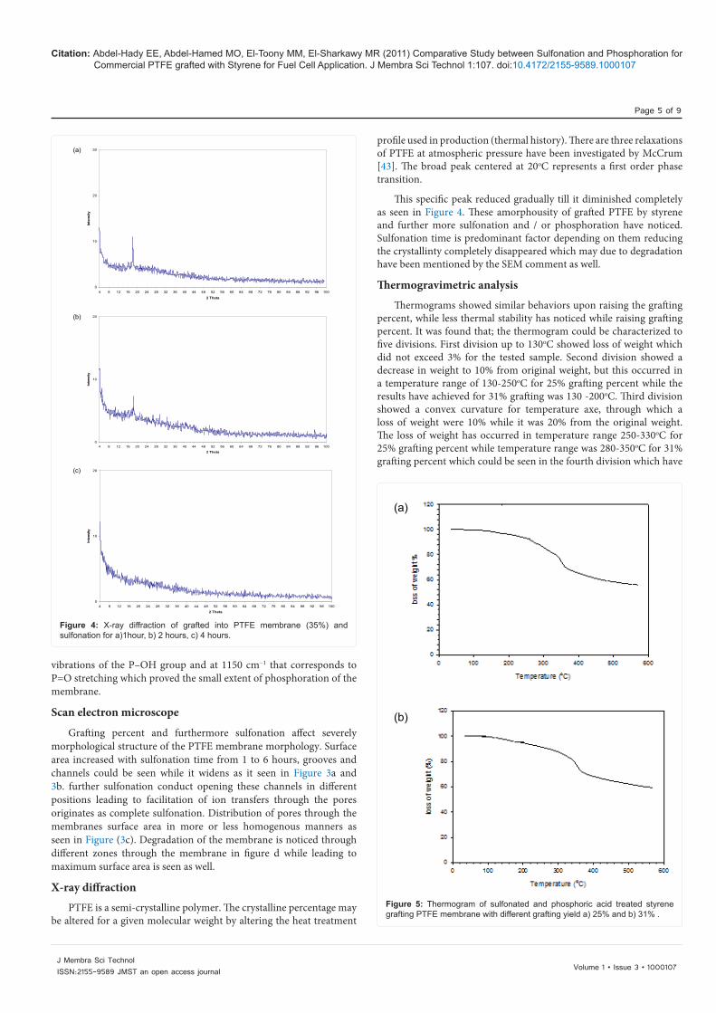
PTFE is a semi-crystalline polymer. The crystalline percentage may be altered for a given molecular weight by altering the heat treatment
profile used in production (thermal history). There are three relaxations of PTFE at atmospheric pressure have been investigated by McCrum [43]. The broad peak centered at 20oC represents a first order phase transition.
This specific peak reduced gradually till it diminished completely as seen in Figure 4. These amorphousity of grafted PTFE by styrene and further more sulfonation and / or phosphoration have noticed. Sulfonation time is predominant factor depending on them reducing the crystallinty completely disappeared which may due to degradation have been mentioned by the SEM comment as well.
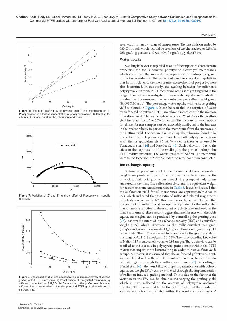
Thermogravimetric analysis
Thermograms showed similar behaviors upon raising the grafting percent, while less thermal stability has noticed while raising grafting percent. It was found that; the thermogram could be characterized to five divisions. First division up to 130oC showed loss of weight which did not exceed 3% for the tested sample. Second division showed a decrease in weight to 10% from original weight, but this occurred in a temperature range of 130-250oC for 25% grafting percent while the results have achieved for 31% grafting was 130 -200oC. Third division showed a convex curvature for temperature axe, through which a loss of weight were 10% while it was 20% from the original weight. The loss of weight has occurred in temperature range 250-330oC for 25% grafting percent while temperature range was 280-350oC for 31% grafting percent which could be seen in the fourth division which have
0
10
20
30
4 8 12 16 20 24 28 32 36 40 44 48 52 56 60 64 68 72 76 80 84 88 92 96 100
2 Theta
Inte
nsity
0
10
20
4 8 12 16 20 24 28 32 36 40 44 48 52 56 60 64 68 72 76 80 84 88 92 96 100
2 Theta
Inte
nsity
0
10
20
4 8 12 16 20 24 28 32 36 40 44 48 52 56 60 64 68 72 76 80 84 88 92 96 100
2 Theta
Inte
nsity
(a)
(b)
(c)
Figure 4: X-ray diffraction of grafted into PTFE membrane (35%) and sulfonation for a)1hour, b) 2 hours, c) 4 hours.
a
(a)
(b)
Figure 5: Thermogram of sulfonated and phosphoric acid treated styrene grafting PTFE membrane with different grafting yield a) 25% and b) 31% .
Citation: Abdel-Hady EE, Abdel-Hamed MO, El-Toony MM, El-Sharkawy MR (2011) Comparative Study between Sulfonation and Phosphoration for Commercial PTFE grafted with Styrene for Fuel Cell Application. J Membra Sci Technol 1:107. doi:10.4172/2155-9589.1000107
Page 6 of 9
Volume 1 • Issue 3 • 1000107J Membra Sci TechnolISSN:2155-9589 JMST an open access journal
seen within a narrow range of temperature. The last division ended by 580oC through which it could be seen loss of weight reached to 52% for 25% grafting percent and was 40% for grafting yield of 31%.
Water uptake
Swelling behavior is regarded as one of the important characteristic properties for the sulfonated polystyrene electrolyte membranes, which confirmed the successful incorporation of hydrophilic group inside the membrane. The water and methanol uptakes capabilities that in turn related to the membranes electrochemical properties were also determined. In this study, the swelling behavior for sulfonated polystyrene electrolyte PTFE membranes consist of grafting yield in the range of 5–35%was investigated in term water uptake and hydration number, i.e. the number of water molecules per sulfonic acid group (H2O/SO3H ratio). The percentage water uptake with various grafting yield is plotted in Figure 6. It can be seen that the sorption of water by sulfonated polystyrene PTFE membrane increases with the increase in grafting yield. The water uptake increase 29 wt. % as the grafting yield increases from 5 to 35% for water. The increase in water uptake for all membranes samples can be reasonably attributed to the increase in the hydrophilicity imparted to the membrane from the increases in the grafting yield. The experiential water uptake values are found to be lower than the bulk polymer gel (namely as bulk polystyrene sulfonic acid) that is approximately 90 wt. % water uptakes as reported by Yamaguchi et al. [44] and Nasef et al. [45]. Such behavior is due to the effect of the suppression of the swelling by the porous hydrophobic PTFE matrix structure. The water uptakes of Nafion 117 membrane were found to be about 20 wt. % under the same condition conducted.
Ion exchange capacity
Sulfonated polystyrene PTFE membranes of different equivalent weights are produced The sulfonation yield was determined as the ratio of sulfonic acid groups per phenyl ring groups of polystyrene anchored in the film. The sulfonation yield and the equivalent weight for each membrane are summarized in Table 3. It can be deduced that the sulfonation yield for all membranes are approximately close to 55% which indicated that the ratio of sulfonated phenyl ring groups of polystyrene is nearly 1/2 This may be explained on the fact that the amount of sulfonic acid groups incorporated to the sulfonated membrane is a function of the amount of polystyrene anchored in the film. Furthermore, these results suggest that membranes with desirable equivalent weights can be produced by controlling the grafting yield [27]. it shows the extent of ion exchange capacity (IEC) and equivalent weight (EW) which expressed as the millie-quivalent per gram (meq/g) and gram per equivalent (g/eq) as a function of grafting yield, respectively. The IEC is observed to increase with the grafting yield in the range of 0.44–1.1 meq/g and 10–35%. The corresponding IEC value of Nafion 117 membrane is equal to 0.93 meq/g. These behaviors can be ascribed to the increase in polystyrene grafts content within the PTFE matrix that impart more benzene ring in order to host sulfonic acids groups. Moreover, it is assumed that the sulfonated polystyrene grafts were anchored within the which provides interconnected hydrophilic cationic regions through the resulting membranes [45]. According to B¨uchi et al. [46], the possibility of preparing membranes with tailored equivalent weight (EW) can be achieved through the implementation of radiation induced grafting method. This is due to the fact that the variation in the EW can be obtained via varying the grafting yield, which in turn, reflected on the amount of polystyrene anchored into the PTFE matrix that led to the determination of the number of sulfonic acid sites incorporated within the resulting membranes. A
Grafting %
0 10 20 30 40
Wat
er u
ptak
e %
0
5
10
15
20
25
30
35
cb
a
Figure 6: Effect of grafting % of styrene onto PTFE membrane on a) Phosphoration at different concentration of phosphoric acid.b) Sulfonation for 4 hours.c) Sulfonation after phosphoration for 4 hours.
0 20000 40000 600000
20000
40000
60000
sample7
Z"
Z'
Figure 7: Variation of Z’ and Z” to show effect of Frequency on specific resistivity.
Grafting %
0 10 20 30 40
Inoi
c rs
istiv
ity (O
hm/c
m)
0
200
400
600
800
a
b c
Figure 8: Effect sulphonation and phosphoration on ionic resistively of styrene grafted onto PTFE membrane. a) Phophoration of the grafted membrane by different concentration of H3PO4. b) Sulfonation of the grafted membrane at different time. c) sulfonation of the phosphorated PTFE grafted membrane at different time.
Citation: Abdel-Hady EE, Abdel-Hamed MO, El-Toony MM, El-Sharkawy MR (2011) Comparative Study between Sulfonation and Phosphoration for Commercial PTFE grafted with Styrene for Fuel Cell Application. J Membra Sci Technol 1:107. doi:10.4172/2155-9589.1000107
Page 7 of 9
Volume 1 • Issue 3 • 1000107J Membra Sci TechnolISSN:2155-9589 JMST an open access journal
high grafting yield will result in a low EW of the membrane, while low grafting yield leads to high EW. Thus, the acquired EW values are in harmony with the aforementioned discussion that shows a decreasing trend with increasing grafting yield. Meanwhile, the corresponding EW value of Nafion 117 membrane is approximately to 1073 g/eq.
Electrical conductivityFigure 7 showed the Cole- Cole plot (Nquist plot) of styrene grafted
PTFE at 300K. The plot shows a high- frequency semi-circle and a low frequency spike for DG. It was reported that, [47] the high- frequency semi-circle is due to the parallel combination of bulk resistance ,because of protons migration, and bulk capacitance, due to immobile polymer chains. Two semicircle curves could be seen which attempt that; two behaviors of the membrane which may due to presence of two active groups SO3H and PO4H 2. These suggestion result in high applicability of such membrane through the fuel cell. The bulk resistance can be calculated from the intercept of low-frequency spike or of high frequency semicircle.
The proton conductivity of sulfonated polystyrene grafted PTFE membranes with various grafting yields measured at room temperature is illustrated in Figure 8. The specific resistivity is decreased with increasing grafting yield. The resistivity decreases from 940 to 225
ohm cm for the phosphorated grafted PTFE membrane while the decrease range for sulfonated grafted membrane ranged from 220 to 34 ohm cm. The optimal decrease of the specific resistivity was result as sulphonation of the phosphorated grafted PTFE membrane by styrene with 35% yield which reached to 5 ohm cm. This results may explained by phosphoration has a limited role for reducing the specific resistivity which is due to leaching out many of phosphoric acid while very small extent have the ability to hanged by the membrane network. Treatment with phosphoric acid enhanced further sulphonation and resulted in the highest reduction of the resistivity. This is because of the ionic conductivity is a function of IEC, solvent uptake and hydration number of the membranes was found to be strongly dependence upon the grafting yield. As the grafting yield increases, more and more sulfonic acid groups are incorporated within the membranes, which led the membranes become more hydrophilic and enable to absorb more water in order to enhance the facilitation of the proton (H+) mobility through the membranes. The decrease in Nafion’s conductivity is probably due to the incomplete regeneration into acidic form during the sample preparation.
Raising the temperature leading to increasing up the kinetic energy of hydrogen proton to be diffused easily through the membrane’s active sites. Temperature expand the pore size of the synthesized membrane an so enhancing the proton passage through which. Temperature has a potential role in activate the sulfonic acid and phosphoric acid hanged by the membrane net matrix which increase their chance for accept and donate the hydrogen proton. All these factors increasing the electrical conductivity of the membrane as it could be seen in the Figure 9. Increasing the EC with the temperature is linear relationship in the range of 25 to 80oC for the PTFE membrane grafted with styrene while it phosphorated prior to be sulfonated.
The membrane used in fuel cell acts as a carrier for proton transport and as a barrier to provide effective separation between the anode and cathode. The former requires the membrane to be as thin as possible, while the latter requires the membrane to be strong enough to avoid damage during the membrane electrode assembly (MEA) fabrication, and during the fuel cell operation. Especially in a DMFC, one side of the membrane is exposed to the liquid methanol solution, and the other side is exposed to the dry gas. Different swelling on the two sides will accelerate the degradation of the fuel cell membrane. In many cases, it is found that the degradation of the fuel cell is not only caused by the lower chemical stability, but by mechanical damage.
Evaluation of the mechanical properties of maximum value of grafting (35%) of the styrene grafted membranes have been evaluated and maximum sulfonation and/ or phosphoratrion was chosen. Hardness measurements showed decrease their value by increasing the heating time of with hydrogen peroxide. These results attempt the availability of the membrane and their durability through the 2 hours however; it noticed more applicability via the first 45 minutes.
ConclusionTo overcome the defects of the commercial membrane (Nafion)
which have mentioned through the present introduction we do our work. First we have chosen cheep commercial membrane, second a hybrid membrane was chosen which inserted through a silica powdered which can be controlled the methanol/water passage. Third defect we could handled the membrane in a wet condition especially when it operated via fuel cell. This membrane proved to be applicable chemically, hydrophilicity, mechanically and thermally. Phosphoration has a limited role in a direct application while it played a very important mission in sulfonation enhancement which resulted in less electrical
Temperature (oC)
20 30 40 50 60 70 80 90
Ele
ctric
al c
ondu
ctiv
ety
(S/C
m)
0.00
0.02
0.04
0.06
0.08
0.10
0.12
Figure 9: Effect of temperature (oC) on the electrical conductivity of the sulphonated the phosphorated PTFE membrane grafted with styrene (35% yield).
Time (minutes)
0 20 40 60 80 100 120
Har
dnes
s (S
hore
-A)
0
20
40
60
80
Figure 10: Effect of chemical stability of sulfonatedted the phosphorated (maximum percent) PTFE membrane grafted with styrene (35% yield).
Citation: Abdel-Hady EE, Abdel-Hamed MO, El-Toony MM, El-Sharkawy MR (2011) Comparative Study between Sulfonation and Phosphoration for Commercial PTFE grafted with Styrene for Fuel Cell Application. J Membra Sci Technol 1:107. doi:10.4172/2155-9589.1000107
Page 8 of 9
Volume 1 • Issue 3 • 1000107J Membra Sci TechnolISSN:2155-9589 JMST an open access journal
resistivity, more water uptake. Duration test efficiently confirmed usage the membranes through fuel cell applications.
References1. Surampudi S, Narayanan SR, Vamos E, Frank H, Halpert G, et al. (1994)
Advances in direct oxidation methanol fuel cells. J Power Sources 47: 377-385.
2. Li J, Sato K, Ichiduri S, Asano S, Ikeda S, et al. (2004) Pre-irradiation induced grafting of styrene into crosslinked and non-crosslinked polytetrafluoroethylene films for polymer electrolyte fuel cell applications. I. Influence of styrene grafting conditions. Eur Polym J. 40 :775-783.
3. Sato K, Ikeda S, Iida M, Oshima A, Tabata Y, et al. (2003) Study on poly-electrolyte membrane of crosslinked PTFE by radiation-grafting, Nucl Instrum Meth B 208: 424-428.
4. Buchi FN, Gupta B, Haas O, Scherer GG (1995) Study of radiation-grafted FEP-g-polystyrene membranes as polymer electrolytes in fuel cells. Electrochim Acta 40, 345-353.
5. Buchi FN, Gupta B, Haas O, Scherer GG (1995) Performance of differently crosslinked, partially fluorinated fuel cell membranes in polymer electrolyte fuel cells. J Electrochem Soc 142: 3044-3048.
6. Huslage J, Brack HP, Geiger F, Buchi FN, Tsukada A, Scherer GG (1998) PSI Scientific Report. Annex V, 1999: 51-52.
7. Huslage J, Rager T, Schnyder B, Tsukada A (2002) Radiation-grafted membrane/electrolyte assemblies with improved interface. Electrochim Acta 48: 247-254.
8. Schmidt TJ, Simbeck K, Scherer GG (2005) Influence of crosslinking on performance of radiation-grafted and sulfonated FEP 25 membranes in H2-O2 PEFC, J. Electrochem Soc 152: A93-A97.
9. Nasef MM, Saidi H, Nor HM, Foo OM (2002) Cation exchange membranes by radiation-induced graft copolymerization of styrene onto PFA copolymer films. II. Characterization of sulfonated graft copolymer membranes. J Appl Polym Sci 76: 1-11.
10. Nasef MM, Saidi H (2003) Preparation of crosslinked cation exchange membranes byradiation grafting of styrene/divinylbenzene mixtures onto PFA films. J Mem Sci 216: 27-38.
11. Nasef MM, Saidi H, Dahlan KZM (2003) Electron beam irradiation effects on ethylene-tetrafluoroethylene copolymer films. Radiat Phys Chem 68: 875-883.
12. Nasef MM, Dahlan KZM (2003) Electron irradiation effects on partially fluorinated polymer films: structure-property relationships. Nucl InstrumMeth B 201: 604-614.
13. Shen M, Roy S, Kuhlmann JW, Scott K, Lovell K, et al. (2005) Grafted polymer electrolyte membrane for direct methanol fuel cells. J Mem Sci 251 :121-130.
14. Doyle M, Rajendran G, in: Vielstich W, Gasteiger HA, Lamm A (2003) (Eds.), Handbook of Fuel Cells—FundamentalsTechnology and Applications.John Wiley and Sons Chichester p. 351.
15. Baglio V, Arico AS, Di Blasi A, Antonucci V, Antonucci PL, et al.(2005) Nafion-TiO2 composite DMFC membranes: physico-chemical properties of the filter versus electrochemical performance. Electrochim Acta 50: 1241-1246.
16. Zeng R, Pang Z, Zhu H (2000) Modification of a Nafion ion exchange membrane by a plasma polymerization process. JElectroanalChem 490: 102-106.
17. Miyatake K, Chikashige Y, Watanabe M (2003) Novel sulfonated poly(arylene ether): a proton conductive polymer electrolyte designed for fuel cells. Macromolecules 36: 9691-9693.
18. Nagarale RK, Gohil GS, Shahi VK, Rangarajan R (2004) Organic-inorganic hybrid membrane: thermally stable cation-exchange membrane prepared by the sol-gel method.Macromolecules 37: 10023-10030.
19. Dargaville TR, George GA, Hill DJT, Whittaker AK (2003) High energy radiation grafting of fluoropolymers.Prog Polym Sci 28:1355-1376.
20. Nasef MM, Hegazy E (2004) Preparation and applications of ion exchange membranes by radiation-induced graft copolymerization of polar monomers onto non-polar films.Prog Polym Sci 29 :499-561.
21. Grot WG (1994) Macromol Symp 82: 161-172.
22. Miyatake K, Iyotani H, Yamamoto K, Tsuchida E (1996) Synthesis of poly(phenylene sulfide sulfonic acid) via poly(sulfonium cation) as a thermostable proton-conducting polymer.Macromolecules 29: 6969.
23. Kuver A, Vogel I, Vielstich W (1994) Distinct performance evaluation of a direct methanol fuel cell. A new method using a dynamic hydrogen reference electrode. J Power Sources 52: 77-80.
24. Hegazy EA, El-Assy NB, Dessouki AM and Shaker MM (1989) ion-containing reverse osmosis membranes obtained by radiation grafting method. Radiat Phys Chem 33: 13-18.
25. Ismail AF, Zubir N , Nasef MM , Dahlan KM, Hassan AR (2005) Physico-chemical study of sulfonated polystyrene pore-filled electrolyte membranes by electrons induced grafting. J of Mem Sci 254: 189-196.
26. Walsby N, Paronen M, Juhanoja J, Sundhoulm F (2001) Sulfonation of styrene-grafted poly(vinylidene fluoride) films. J Appl Polym Sci 81: 1572-1580.
27. Nasef MM (1999) Proton exchange membranes by radiation-induced graft copolymerization of styrene onto fluorinated polymers. J Appl Polym Sci 78:2443-2453
28. Chen J, Asano M, Maekawa Y, Yoshida M (2006) Suitability of some fluoropolymers used as base films for preparation of polymer electrolyte fuel cell membranes. J of Mem Sci 277: 249-257.
29. Chapiro A (1962) Radiation chemistry of polymeric systems. Interscience New York vol. IV, pp. 131±150: 177-190.
30. Siyam T (1994a) Effect of polydiallylethylamine- hydrochloride as a template for the radical polymerization of acrylic acid in aqueous solution. Macromolecular Reports A31 (Suppl 3 & 4) 383-392.
31. Siyam T (1994b) Gamma radiation induced copolymerization of diallylethylaine hydrochloride with acrylamide in aqueous solution. Macromolecular Reports A31 (Suppl. 3 & 4) 371.
32. Siyam T (1997) Gamma radiation-induced preparation of some polyelectrolyte and its use for treatment of waste water. In: Chermisinof (Ed.) Handbook of Engineering Polymeric Materials Chap 9 Dekker New York 119-135.
33. North AM, Reed GA (1961) Difusion controlled termination during the initial stage of free radical polymerization of methyl methacrylate. Trans Farad Soc 57 (1) 59.
34. Odian G (1970) Principles of polymerization. 3 McGrawHill, New York 165.
35. Hegazy EA, Kamal H, Khalifa, Abd, El-Rehim H (1995a) Ion-containing membrane obtained by irradiation grafting on vinyl and acrylic monomers onto polymeric substrates. 3rd Arab Int Conf on Polymer Sci and Technology Mansoura Univ Mansoura Egypt II 329.
36. Lai JY, Chen, MA, Shih, CY, Hsu, KY (1981) Acrylic acid g-ray irradiation grafted nylon 4 membrane. J Appl Polym Sci 49: 1197.
37. Chapiro A, Dubieu J (1977) Influence of solvents on the molecular association and on the radiation initiated polymerization of acrylic acid. Eur Polym J 13: 563-577.
38. Chapiro A (1981a) Auto-acceleration in free radical polymerization under precipitating condition. ACS Symposium series 175: 233-252.
39. Chapiro A (1981b) Auto-acceleration in free radical polymerization caused by orinated monomer-polymer association complex. Pure Appl Chem 643-655.
40. Gromov VF, Galperina NL, Osmanov, Khomikovskii PM, Abkin AD (1980) Efect of solvent on chain propagation and termination reaction rates in radical polymerization. Eur Polym J 16: 529-535.
41. Kurenkov VF, Verihznikova AS, Myagchenkov VA (1984) Peculiarities of the preparation of copolymers of acrylamide with sodium acrylate in inverse emulsion. Eur Polym J 20: 357-360.
42. Zhi-Li X, Chapiro A, Schmitt N (1993) Grafting of vinylimidazole into air irradiated polymer films-grafting into Teflon-FEP. Radiat Phys Chem 29: 301-303.
43. McCrum NG (1959) An internal friction study of polytetrafluoroethylene. J Polym Sci 34:355-369.
44. Yamaguchi K, Miyata F, Nakao S (2003) Pore-filling type polymer electrolyte membranes for a direct methanol fuel cell. J Mem Sci 214: 283-292.
45. Nasef MM, Zubir NA, Ismail AF, Dahlan KZ, Saidi H (2003) New pore-filled polymer electrolyte membranes by electrons induced grafting, in: Proceedings of the International Symposium on Renewable Energy: Environment Protection and Energy Solution for Sustainable Development. Malaysian Institute of Energy and Malaysia Energy Center Kuala Lumpur September 14-17.
Citation: Abdel-Hady EE, Abdel-Hamed MO, El-Toony MM, El-Sharkawy MR (2011) Comparative Study between Sulfonation and Phosphoration for Commercial PTFE grafted with Styrene for Fuel Cell Application. J Membra Sci Technol 1:107. doi:10.4172/2155-9589.1000107
Page 9 of 9
Volume 1 • Issue 3 • 1000107J Membra Sci TechnolISSN:2155-9589 JMST an open access journal
46. Buchi FN, Gupta B, Haas O, Scherer GG (1995) Study of radiationgrafted FEP-G-polystyrene membranes as polymer electrolyte in fuel cells. Electrochem Acta 40: 345-353.
47. Hema M, Selvasekarapandian S, Nithya H, Sakunthala A and Arunkumar D. (2009) Structural and ionic conductivity studies on proton conducting polymer electrolyte based on polyvinyl alcohol. 15: 487-491.


![GRAFTED TOMATO - Iserv1].pdf · GRAFTED TOMATO Grafted onto ... Grafting joins the top part of one plant (the scion) to the root ... (TPIE) - January 18-20, 2012 Spring Trials in](https://img.pdfslide.us/doc/110x75/5aa1ea047f8b9a436d8c452d/grafted-tomato-1pdfgrafted-tomato-grafted-onto-grafting-joins-the-top-part.jpg)