Embed Size (px)
Citation preview

Journal of Structural Biology 168 (2009) 190–199
Contents lists available at ScienceDirect
Journal of Structural Biology
journal homepage: www.elsevier .com/ locate/yjsbi
DNA-tethered membranes formed by giant vesicle rupture
Minsub Chung, Randall D. Lowe, Yee-Hung M. Chan, Prasad V. Ganesan, Steven G. Boxer *
Department of Chemistry, Stanford University, Stanford, CA 94305-5080, USA
a r t i c l e i n f o
Article history:Received 3 February 2009Received in revised form 11 June 2009Accepted 21 June 2009Available online 26 June 2009
Keywords:Tethered lipid membraneSurface immobilized DNAGiant unilamellar vesicles
1047-8477/$ - see front matter � 2009 Elsevier Inc. Adoi:10.1016/j.jsb.2009.06.015
* Corresponding author. Address: Department of Ch380 Roth Way, Stanford, CA 94305-5080, USA. Fax: +
E-mail address: [email protected] (S.G. Boxer).
a b s t r a c t
We have developed a strategy for preparing tethered lipid bilayer membrane patches on solid surfaces byDNA hybridization. In this way, the tethered membrane patch is held at a controllable distance from thesurface by varying the length of the DNA used. Two basic strategies are described. In the first, single-stranded DNA strands are immobilized by click chemistry to a silica surface, whose remaining surfaceis passivated to prevent direct assembly of a solid supported bilayer. Then giant unilamellar vesicles(GUVs) displaying the antisense strand, using a DNA–lipid conjugate developed in earlier work [Chan,Y.-H.M., van Lengerich, B., et al., 2008. Lipid-anchored DNA mediates vesicle fusion as observed by lipidand content mixing. Biointerphases 3 (2), FA17–FA21], are allowed to tether, spread and rupture to formtethered bilayer patches. In the second, a supported lipid bilayer displaying DNA using the DNA–lipidconjugate is first assembled on the surface. Then GUVs displaying the antisense strand are allowed totether, spread and rupture to form tethered bilayer patches. The essential difference between these meth-ods is that the tethering hybrid DNA is immobile in the first, while it is mobile in the second. Both strat-egies are successful; however, with mobile DNA hybrids as tethers, the patches are unstable, while in thefirst strategy stable patches can be formed. In the case of mobile tethers, if different length DNA hybridsare present, lateral segregation by length occurs and can be visualized by fluorescence interference con-trast microscopy making this an interesting model for interactions that occur in cell junctions. In bothcases, lipid mobility is high and there is a negligible immobile fraction. Thus, these architectures offera flexible platform for the assembly of lipid bilayers at a well-defined distance from a solid support.
� 2009 Elsevier Inc. All rights reserved.
1. Introduction
Supported lipid bilayers (SLBs) have been widely used as a mod-el for cell membranes (Sackmann, 1996; Chan and Boxer, 2007)and to investigate membrane components including proteins in asimpler context apart from the complex cellular environment. SLBsare assembled by Langmuir–Blodgett techniques or spontaneousfusion of unilamellar vesicles on carefully prepared surfaces, usu-ally hydrophilic solid supports, such as glass (Seu et al., 2007), sil-ica, mica (Richter et al., 2006), or TiO2 (Rossetti et al., 2005).Although SLBs have the advantages of simple formation, easy han-dling and are well-suited for investigation by a suite of surface sen-sitive methods due to their planar geometry, the close proximity ofthe lower leaflet to the solid support often leads to unfavorableinteractions with integral membrane proteins. Recognizing thislimitation, many groups have described methods to separate themembrane from the solid support including polymer cushionedbilayers (Wagner and Tamm, 2000; Merzlyakov et al., 2006;Renner et al., 2008), polymer tethered membranes (Naumann
ll rights reserved.
emistry, Stanford University,1 650 723 4817.
et al., 2002; Purrucker et al., 2004; Koper, 2007) and tethered ves-icles (Yoshina-Ishii and Boxer, 2003; Stadler et al., 2004; Yoshina-Ishii et al., 2005).
In this paper, we describe two approaches for tethering lipidmembranes using DNA linkages to separate the membrane fromsurface interactions. In one strategy (Figs. 1A and 2), DNA teth-ers are coupled directly to the substrate by using click chemis-try (Kolb et al., 2001) to graft alkyne-functionalized DNA onto aglass or silica substrate which is silanized by azide-terminatedalkyl silane. Giant unilamellar vesicles (GUVs, diameter of 20–60 lm) displaying complementary DNA-functionalized lipidsbind to the DNA-functionalized surface via hybridization, thenrupture and spread to form planar tethered bilayer patches. Inan alternative strategy (Fig. 1B), DNA-conjugated lipids areincorporated into an SLB, which allows the DNA tethers to re-main mobile. Then GUVs displaying the antisense DNA arebound by hybridization and ruptured to form bilayer patches.In both approaches, the length of the DNA and hence distanceof the tethered bilayer from the surface can be controlled at willand, as far as we know, this is a unique feature. The first systemproduces stable patches, while in the second interesting dy-namic behavior is observed, in part because the tethers aremobile.

Fig. 1. Schematic diagram of DNA-tethered membrane formation by GUV rupture onto (A) self-assembled alkylsilane monolayers, see Fig. 2 for details; and (B) supportedlipid bilayers. The GUV membrane contains DNA-linked lipids, which mediate vesicle binding and rupture. In (A), the glass substrate is functionalized with an azide-terminated alkyl-siloxane monolayer to which complementary DNAs are immobilized via the click reaction (see Fig. 2). The distance from the substrate is controllable byadjusting the DNA length, about 8 nm for 24 mer and 16 nm for 48 mer DNA. In (B), a supported lipid bilayer presenting DNA is first formed on the glass substrate, and thenexposed to GUVs presenting the complementary DNA to form a DNA-tethered membrane. In both cases, tethered membrane patches whose area is approximately that of theoriginal GUVs are formed.
Fig. 2. The general synthetic scheme to make the immobilized DNA surface (c.f. Fig. 1A). 50 alkyne modified DNA (Alkyne-C6-50 DNA) is clicked to the azide-modified glasssurface in step 1 at approximately 1% coverage, and the remaining free azides are then clicked with ethynyl phosphonic acid in step 2.
M. Chung et al. / Journal of Structural Biology 168 (2009) 190–199 191
2. Materials and methods
2.1. Formation of supported bilayers
Small unilamellar vesicles (SUV) were prepared by vesicleextrusion through 100 nm polycarbonate membranes (Whatman)as described previously (Yoshina-Ishii and Boxer, 2003). They werecomposed of egg phosphatidylcholine (EggPC, Avanti Polar Lipids,Alabaster, AL), 1 mol% Texas Red 1,2-dihexadecanoyl-sn-glycero-
3-phosphoethanolamine (TR-DHPE, Molecular Probes, Eugene,OR) or 2 mol% of Oregon Green� 488 1,2-dihexadecanoyl-sn-glyce-ro-3-phosphoethanolamine (OG-DHPE, Molecular Probes), andDNA–lipid conjugates (Chan et al., 2008) anchored at the 50 endand with either 24- or 48-mer poly T as the sequence. DNA–lipidconjugates were dissolved in a 1:1 mixture of acetonitrile andwater. An aliquot of this solution was mixed with 40 ll of10 mM phosphate buffered saline (PBS) without salt to achievethe desired average DNA mol%. Then, 10 ll of extruded SUV

192 M. Chung et al. / Journal of Structural Biology 168 (2009) 190–199
suspension (10 mg/ml) was added and incubated overnight at 4 �C.In the case of two different lengths of DNA tether, an equimolarmixture of 50-lipid-24-mer poly T and 50-lipid-TAACTACAGAATTTATACTATCCCGGGTCACAGCAGAGAAACAAGATA-30 (a 48 mer) wasused.
Supported lipid bilayers were formed by vesicle fusion byexposing a glass cover slip to the above SUVs that were dilutedto 0.2 mg/ml in 10 mM PBS, pH 7.2, containing 100 mM sodiumchloride, for 10 min. The glass cover slips (VWR) were cleaned bysoaking in 90 �C 7� ICN detergent (diluted 1:6 in double distilledwater, ICN Pharmaceuticals, Costa Mesa, CA), rinsed extensivelyin double distilled water, and baked at 400 �C for 4 h. The ruptureof GUVs rarely occurred on the SLBs containing less than 0.1 mol%DNA–lipid conjugates, while most GUVs ruptured above 0.5 mol%DNA–lipid conjugates. It is hard to make SLBs containing morethan 0.5 mol% DNA–lipid, probably due to high negative chargeof DNAs. These membranes were observed with a Nikon TE300 in-verted epifluorescence microscope using a 40� oil immersionobjective (NA 1.2).
Protein micro-patterned lipid bilayer surfaces were prepared bythe method described previously (Kung et al., 2000). 100 lmsquare bovine serum albumin (BSA) barriers were transferred frompolydimethylsiloxane (PDMS, Dow Corning, Midland, MI) elasto-mer stamps containing a microscale pattern. The PDMS stampswere formed by curing on silicon wafers patterned by standardphotolithographic techniques. Then an SUV suspension was addedto form SLBs separated by BSA square grids.
2.2. Preparation and characterization of surfaces displayingimmobilized DNA
11-azidoundecyl-1-trimethoxysilane was prepared from 11-bromoundecyl-1-trimethoxysilane (Gelest) according to a pub-lished procedure (Fu and Yu, 2001). Azidosilane monolayers werevapor-deposited in a glass vacuum desiccator (Jencons part No.08-625A) fitted with a Teflon stopcock. Hundred microliters of neatazidosilane was injected onto filter paper in the bottom of the des-iccator, and 0.5 g of MgSO4�7H2O was placed in a foil boat in thebottom of the desiccator as a water source for the silanization reac-tion. The detergent cleaned glass slides were oxygen plasmacleaned for 5 min. prior to deposition and placed in a slide racksupported above the azidosilane liquid. The desiccator was thenevacuated on a Schlenk line to �300 mTorr with a liquid nitro-gen-trapped mechanical pump. The Teflon valve on the desiccatorwas then closed, and the chamber was placed in a 110 �C preheatedoven for 48 h. After deposition, the surfaces were rinsed with tolu-ene and isopropanol, and then dried in a stream of nitrogen.
Azide-modified glass surfaces were exposed for 2 h (Fig. 2) toaqueous solutions containing: 100 lM CuSO4, 100 lM tris(tria-zolylmethyl)amine Cu ligand, 1 mM sodium ascorbate, and 5 lMalkynyl-oligonucleotides. These are 50 alkynyl modified polyT oli-gonucleotides with a six carbon linker (Alkynyl-C6-polyT), either24 or 48 mer. Following this, the surfaces were rinsed with waterand exposed to a second click solution containing: 100 lM CuSO4,100 lM TTMA Cu ligand, 1 mM sodium ascorbate, and 1 mM ethy-nyl phosphonic acid for 1 h, to passivate unreacted azide. Theclicked surfaces were then rinsed with 3� saline–sodium citrate(SSC) buffered solution, 150 mM Hepes/0.1% SDS/1� SSC, and final-ly 150 mM Hepes/150 mM NaCl in water to remove nonspecificallyadsorbed oligonucleotides.
The thickness change accompanying the formation of azidosi-lane-monolayer was monitored by single-wavelength ellipsometryusing Si wafers with �260 nm thick SiO2 films instead of glassslides. The Si chips (0.5 � 0.5 cm) were detergent cleaned, bakedand silanized as described above, and the exact thicknesses ofthe SiO2 layer and azidosilane-monolayer from the Si mirror were
measured before and after silanization. The auto-nulling-four-zoneanalysis of the ellipsometer (Nanofilm Technologie, Goettingen,Germany) was used to generate delta and psi values, with532 nm light and 54� incidence angle. The results were fit to amodel of Si/SiO2/monolayer with parameters of nSi = 4.1562,jSi = 0.0419, nSiO2 = 1.4605 and nmonolayer = 1.4578 (Ali et al.,2008). The root-mean-square (RMS) surface roughness changewas measured by atomic force microscopy (AFM), performed incontact mode at 1 Hz scan rate in air using a Nanoscope III (DigitalInstruments Inc., Santa Barbara, CA), using silicon cantilevers. RMSroughness, defined as the average height (z) taken from the meandata plane, was calculated for a 1 � 1 lm area using the instru-ment software.
The density of DNA molecules on the substrate is roughly esti-mated by the fluorescence intensity from complementary Cy5-la-beled DNA. DNA immobilized substrates were prepared asdescribed above using solutions with several different alkynyl-DNA (24mer polyT) concentrations (0, 1, 1.5, 2.5 and 5 nmol/ml),followed by passivating with ethynyl phosphonic acid and rinsingsteps. The dependence on incubation time was also tested, but be-cause there was no significant difference after 2 h, every reactionwas incubated for 2 h. 5 lM of 50-Cy5-modified 24 mer polyA oli-gonucleotides in buffered solution (pH 7.2) containing 10 mM so-dium phosphate and 0.1 M NaCl were introduced onto thesubstrates and incubated for 1 h. Nonspecifically adsorbed oligo-nucleotides were removed using the same rinsing procedure asfor DNA immobilization. After Cy5-labeled complementary DNAwas bound, the fluorescence intensity was determined immedi-ately with a Nikon TE300 (Nikon, USA; New York, USA) invertedmicroscope using a 100� oil immersion objective illuminatingwith a high-pressure mercury lamp and an excitation filter trans-mitting 590–650 nm and emission filter of 663–738 nm. The fluo-rescence signal was detected with a cooled 16-bit CCD camera(Roper-scientific, Tucson, AZ), and the data were processed withMetamorph imaging software. To correlate the average fluores-cence intensity with a surface density, a calibration measurementwas performed. For this purpose, solid supported membranes of1-palmitoyl-2-oleoyl-sn-glycero-3-phosphocholine (POPC; AvantiPolar Lipid) with 0, 0.26, 0.78 and 1.3 pmoles/cm2 (equivalent toan SLB containing 0.5 mol% DNA) of 50 poly T DNA–lipid conjugateswere prepared and measured in the exactly same way as describedfor the immobilized DNA surfaces. A comparison of fluorescenceintensities per identical area provides the number of active DNAson the substrate. It is expected that some inaccessible DNA is pres-ent on the SLB substrate. Although DNA–lipid conjugate is added tothe outer leaflet of the SUV, during formation, both the inner andouter surface of the SUV may end up facing the glass support.While DNA may be repelled from the surface and largely end upon the upper leaflet, where it can bind the fluorescently labeledantisense strand, the precise distribution is not known, and sothe amount of DNA–lipid conjugate added to the SUVs representsan upper limit to the amount available, and amounts are comparedwith this limit.
2.3. Giant unilamellar vesicle preparation and tethered membraneformation
GUVs ranging in size from 20 to 60 lm were prepared as de-scribed previously (Longo and Ly, 2007) with minor modifications.Phospholipid compositions in GUVs are egg PC with 1 mol% TR-DHPE for visualization and 1 mol% of DNA–lipid conjugates witheither 24- or 48-mer polyA as the sequence. In the case of two dif-ferent lengths of DNA tethers, an equimolar mixture of 50-lipid-24-mer polyA and 50-lipid-TATCTTGTTTCTCTGCTGTGACCCGGGATAGTATAAATTCTGTAGTTA-30 (a 48 mer) was used. When the DNA–lipid conjugates were added to the lipid mixture before

M. Chung et al. / Journal of Structural Biology 168 (2009) 190–199 193
electroformation, 1 ll of 0.3 mM DNA–lipid conjugate aqueoussolution was mixed with 50 ll of 0.5 mg/ml lipid mixture dissolvedin 2:1 choloform:methanol, then this was coated on Pt electrodes.When DNA–lipid conjugates were added after the GUV prepara-tion, a desired amount of the DNA–lipid conjugate stock solutionwas mixed with the GUV suspension in 0.5 M sucrose solution toachieve approximately 1 mol% DNA–lipid and incubated overnightat 4 �C, as described above for SUVs. The GUVs were stored at 4 �Cand used within 2 days.
DNA-tethered lipid membrane patch formation from the GUVswas slightly different for the two approaches. The DNA immobi-lized glass cover slips (Fig. 1A) were covered by a CoverWell perfu-sion chamber gasket (9 mm diameter, 0.5 mm thickness, MolecularProbes), and filled with 40 ll of 10 mM PBS containing 240 mM so-dium chloride for osmotic balance with the 0.5 M sucrose solutioninside the GUVs. 5 ll of GUV suspension (0.2 lg/ml) in 0.5 M su-crose was added through the hole of the gasket. The GUVs settleddown and made contact to the substrate surface due to the densesucrose solution inside. As DNA hybridization progressed, sponta-neous rupture of GUVs to form tethered membrane patches wasmonitored by epifluorescence and confocal microscopy. Afterabout 20 min, excess vesicles were removed by rinsing with PBSbuffer. Because of the flow stress of the washing buffer, some flat-tened GUVs (see below) were ruptured. The rupture of GUVs canalso be induced by osmotic shock by exchanging the buffer to10 mM PBS with 50 mM NaCl, though this did not work for all flat-tened GUVs. In the case of the mobile DNA substrate (Fig. 1B), thesame amount of GUV suspension was pipetted directly above theSLB which was kept in 10 mM PBS buffer with 240 mM NaCl underthe well of the gasket. All SLBs under the tethered patches contain2 mol% of OG dye, not seen in the figures because TR filters wereused. The tethering process was similar, though the stability ofthe resulting patches was very different as discussed below.
2.4. Fluorescence interference contrast (FLIC) microscopy
Variable incidence angle FLIC (VIA-FLIC) data provide informa-tion on the distance between the solid support and the tethered bi-layer patch (Ajo-Franklin et al., 2005a,b). Three systems wereexamined: (i) patches tethered using polyA/T 24 mer DNA oligonu-cleotides to supported bilayers assembled on SiO2 films �230,�260 and �330 nm thick on Si wafers; (ii) bilayer patches tetheredwith a mixture of nonrepeating 48 mer and polyA/T 24 mer DNAoligonucleotides to supported bilayers on SiO2 films of thickness�260 nm on Si wafers; and (iii) tethered bilayer patches hybridizedwith polyA/T 48 mer DNA covalently attached to the solid supportformed on SiO2 films of thickness �260 nm and �330 nm on Si wa-fers. VIA-FLIC data were fit in Matlab, largely using the previouslydescribed model (Ajo-Franklin et al., 2005a,b). Briefly, the hydro-phobic region of lipid bilayers was defined to be 3.78 nm thick,and Texas Red was modeled as equally distributed between twolayers, each 0.1 Å from the top and bottom bilayer/water inter-faces, respectively. The absorption transition dipole orientationwas allowed to vary initially before being fixed at 60� relative to bi-layer normal. This value is quite different from the expected valuenear 90� (Ajo-Franklin et al., 2001). This difference may be becausethe DNA-tethered lipid membranes are more prone to fluctuationsthan a bilayer directly on a solid support, although deviations fromexpected values have been reported for other dyes in supportedbilayers (Sund et al., 1999). Transmission data for the microscopefilters and absorption and emission spectra for the dyes were pro-vided by the manufacturers and used to characterize the wave-length dependence of excitation and emission in the model.Thicknesses of the SiO2 spacer layer separating the lipids fromthe Si mirror were determined by ellipsometry. In the model,two free parameters were used for the fit – a distance parameter
and a scaling factor. For tethered membranes hybridized withDNA covalently linked to the solid support, the water layer thick-ness d0 beneath the bilayer was the variable distance parameter.For tethered membranes attached to supported bilayers, d0 wasset to 1.4 nm, and the 3.78 nm thickness of the lower (supported)bilayer was also included in the model. The Fresnel reflection andtransmission coefficients at the interfaces of these two layers wereincluded by matrix algebra in the ‘bulk’ substrate beneath the layerof interest, extending the approach of Lambacher and Fromherz(2002). The variable distance parameter in this case was definedas dsep, the thickness of the water layer between the lower (sup-ported) bilayer and the tethered membrane patch.
2.5. Confocal microscopy and fluorescence recovery after photo-bleaching (FRAP) analysis
Confocal imaging was performed using a Leica TCS SP2 AOBS la-ser scanning confocal microscope. For imaging GUVs and tetheredmembrane patches, the specimens were formed on coverslips asdescribed above. TR was excited with a 594 nm HeNe laser lineset at 20–30% of maximum laser output (4 mW) and imaged witha 600–640 nm band-pass filter using a 100� Plan-Apochromat oilimmersion objective (NA 1.4) at a definition of 1024 � 1024 pixelswith the pinhole set at 1 airy disk. A series of optical sections witha z-spacing of 122 nm were taken and collected using the Leicaconfocal software. 3D reconstruction of Z-stack images were pro-cessed by Volocity (Improvision, Lexington, MA) visualizationsoftware.
An automated FRAP module in the Leica confocal software wasused for diffusion coefficient measurements by spot photo-bleach-ing. DNA-tethered membrane patches, SLBs formed from GUVs,and SLBs formed by small vesicle fusion were measured withinthe same hour to minimize atmospheric temperature differences.The same GUVs were used to form both tethered patches and SLBs.Three samples were examined for each lipid bilayer and at leastfive spots on each sample were measured. Each FRAP experimentstarted with six pre-bleaching image scans using a 100� oilimmersion objective (NA 1.4) with excitation from a 594 nm HeNelaser line set at 25% of maximum laser output (4 mW) and detec-tion with a 600–640 nm band-pass filter at a definition of256 � 256 pixels with the pinhole set at 1 airy disk, followed bybleaching of a 3–5 lm circular spot in the center of a round 40–60 lm diameter tethered membrane patch for 2.08 s, using a488 nm line of high-powered argon laser (100% of 200 mW fulloutput). Post-bleaching image acquisition was immediately startedto monitor fluorescence recovery, at the same setting as pre-bleaching. Time intervals of each image were adjusted from 208to 300 ms to collect enough data points while minimizing furtherphoto-bleaching during recovery.
Diffusion coefficients were estimated following the approach ofJonsson et al. (2008) with simplifications, a modification of the tra-ditional integral method of Axelrod et al. (1976). After the back-ground intensity, defined as the average intensity of the regionsthat is devoid of lipid membrane was subtracted, the average fluo-rescence intensity, B(t), inside a circle of radius R centered on thebleached region and average intensity U(t) of TR-labeled lipidmembrane regions far apart from bleached spot were obtained.Then, FRAP recovery curves were normalized as the intensity ratioof bleached region/unbleached region (Phair and Misteli, 2000), tocorrect the loss of fluorescence caused by imaging.
IðtÞ ¼ BðtÞUðtÞ ð1Þ
Circular averaging of the images around the center of the bleachedspot was performed to reduce the noise of the intensity profile.

194 M. Chung et al. / Journal of Structural Biology 168 (2009) 190–199
Fluorescence intensities of each pixel, I(x, y, t), the same distance rfrom the center was averaged to yield I(r, t). Under the assumptionthat bleaching profiles generated by the scanning beam can be de-scribed by a Gaussian function (Braga et al., 2004; Jonsson et al.,2008), because of diffusion during bleaching, the initial intensityprofile after bleaching, I(r, 0) can be fitted to:
Iðr;0Þ ¼ I0 1� K expð�r2=w2Þ� �
ð2Þ
where I0 is the intensity before bleaching, and K and w are deter-mined by fitting (Fig. 7B). The solution of Fick’s second law for thisinitial expression can be shown to be:
IðtÞ ¼ 1� Kw2
R2 1� ð1� bÞ exp � R2
w2ð1þ t=sÞ
!
�b exp � R2
w2
!!ð3Þ
where R is the radius of a circle centered on the bleached spot, b isthe immobile fraction, and the diffusion coefficient D is calculatedfrom s = w2/4D. Parameters s and b are obtained from the fit of thisequation to the normalized FRAP recovery curves (Fig. 7C). All fit-tings procedures were performed by using nonlinear regression inMATLAB.
In most previous reports describing lateral diffusion coefficientcomparisons, SLBs were made by Langmuir–Blodgett transfer orsmall vesicle fusion methods. However, tethered lipid bilayersare small roughly circular patches less than 100 lm in diameter;likewise SLBs made by GUVs rupture on glass substrates form cir-cular supported lipid bilayer patches of the same dimensions astethered membrane patches. Therefore, the results of SLBs formedby GUV rupture as well as continuous SLBs were tested andcompared.
Fig. 3. Estimation of click immobilized DNA density. DNA immobilized substratesare prepared with the click reaction for 2 h using different concentrations ofalkynyl-oligonucleotides. Cy5-labeled complementary DNA was then hybridizedand its fluorescence intensity, reflecting the immobilized DNA density, wasmeasured. Fluorescence intensities are calibrated with supported lipid bilayersdisplaying known amounts of DNA–lipid conjugates (blue triangles and dotted line,see text). The apparent surface density of immobilized DNA incubated with labeledalkynyl-oligonucleotides concentration is then estimated (red squares).
3. Results and discussion
3.1. Fabrication and characterization of the DNA grafted surface
We have designed two kinds of DNA-presenting surfaces ontowhich lipid membranes can be tethered. One surface has cova-lently bound DNA tethers (Fig. 1A), and the other is a DNA-present-ing supported lipid membrane (Fig. 1B). In the latter case, the glasssubstrate is covered by a lipid membrane, which prevents tetheredvesicles, GUVs or the membrane patches reported here from inter-acting with the glass surface. Furthermore, the DNA–lipid conju-gates are free to diffuse laterally in both the supported lipidmembrane and the tethered patch, and thus the hybridized tethersshould also diffuse; this is a major difference between the architec-tures in Fig. 1A and B.
For the covalently linked DNA system, phosphonic acid termi-nation prevents the exposed hydrophobic azide monolayer frominteracting nonspecifically with the lipid membrane, maintainingthe overall stability of the tethered membrane. Thickness changesof the surfaces during preparation of the DNA bound substratewere analyzed by ellipsometry and AFM was used to analyze thetopography. These thickness measurements were done on flat Siwafers with SiO2 films of thickness �260 nm. The average thick-ness change measured by ellipsometry after azidosilane-mono-layer assembly is 15–20 Å, consistent with the expected chemicalstructure. RMS surface roughness measured by AFM of the Si/SiO2 wafer (<2 Å) increased to �1 nm after the DNA immobiliza-tion. This slight roughness increase is typical for silanized surfaces(Popat et al., 2003), and possibly reflects imperfect coating of thealkyl silane. Although this small roughness does not hinder the for-mation and stability of the tethered membrane and is small com-pared with the tether length (Naumann et al., 2003), it may be
an important variable to consider in some high sensitivityapplications.
The density of DNA coupled to the azidosilane-covered surfacewas estimated by fluorescence as described in the Materials andMethods. Cy5-labeled complementary DNA was hybridized toDNA on the surface, and the fluorescence intensity was convertedto a number density per area by comparing the intensity with thatof SLBs presenting a known mol fraction of DNA (Ajo-Franklinet al., 2005a,b). Because the fluorescence is from a small fractionof a monolayer, it is very weak, and the experimental errors arequite large. Fixing the incubation time at 2 h, the DNA coverage in-creases when a higher concentration of alkynyl-oligonucleotides isused (Fig. 3), and varies from about 1.2 to 2.6 pmol/cm2 (equivalentto an SLB displaying �1 mol% DNA), when 5 lM alkynyl-oligonu-cleotides was used. Approximately 700 pmol/cm2 of azide groupsare present on the surface based on the number of SiOH groups/cm2 (Wasserman et al., 1989). Although only a small fraction ofsurface azides underwent the click reaction with alkynyl-DNA,higher densities of immobilized DNA density were not pursued be-cause this range of DNA coverage was sufficient to allow stabletethering of membranes. Reproducible spontaneous GUV ruptureis observed when 5 lM alkynyl-DNA was incubated for 2 h; there-fore, the DNA immobilized substrates in the rest of this study wereprepared using this set of conditions.
3.2. Tethered lipid membrane patch formation by GUV rupture
Tethered membrane patches were formed by the introduction,binding, and subsequent rupture of GUVs presenting complemen-tary DNA onto the two types of surfaces described above. DNA–li-pid conjugates were inserted into the GUVs by two differentmethods. First, DNA–lipid conjugates were included in the lipidmixtures before electrode coating and GUV electroformation, sothe mol% of DNAs in the GUV should be determined by the compo-sition of the lipid mixture. Because the inner and outer leaflets ofGUVs formed by electroformation are expected to be identical,DNAs are displayed on both the inside and outside of the GUVs,and DNA is consequently displayed on the top surface of the teth-ered patch in the final assembly; this can be used to tether vesicleson the upper surface of the patch or for building another layer(data not shown). Applications of these patches as platforms formore complex assemblies and processes will be discussed insubsequent work. Second, DNA–lipid conjugates were mixed with

Fig. 4. Giant vesicle to tethered membrane patch transformation observed byfluorescence microscopy. These images are of stable tethered membranes withimmobile tethers (Fig 1A); those with mobile tethers are very similar. Theepifluorescence microscopy images, left side, and confocal microscopy images inthe corresponding state, right side, are displayed in parallel. While (F) is exhibitedparallel to the surface, (B, D and H) are 20� tilted to show a better view of theirthree-dimensional shape. (A and B) When the GUV starts to bind via DNAhybridization, only the bottom part of vesicle is in contact with the surface andshows a ring shape. Meanwhile, the upper part of the vesicle out of the focal planeappears as a cloudy halo around the ring. (C and D) Further binding of DNA from thevesicle to the surface flattens the vesicle asymmetrically. (E and F) Eventually, theupper membrane ruptures. Afterwards, a single bilayer remains (dark area) withsome transient double bilayer (bright regions). (G and H) After all of the upperbilayer spreads, a homogeneous tethered membrane is formed. While the epifluo-rescence microscopy images are taken from the same GUV in about 5 min, theconfocal microscopy images take much longer to collect and are of different GUVscaptured at comparable times (see text). Scale bar of epifluorescence microscopy is15 lm.
M. Chung et al. / Journal of Structural Biology 168 (2009) 190–199 195
already-formed GUVs, so DNA–lipids should insert only on the out-side of the GUVs, as is the case when DNA–lipids are added to SUVs(Yoshina-Ishii et al., 2006), and therefore the top leaflet of the teth-ered bilayer, which was the inner leaflet of a GUV, will not displayDNA. Consistent with this, vesicles displaying the antisense strandcould not be tethered to this upper surface (data not shown). Be-cause the DNA displayed on the tethered bilayer plays no role inthe experiments described below, the first DNA insertion methodwas mostly used.
GUV rupture to form tethered membrane patches was indistin-guishable whether mobile or immobile DNA tethers were used;however, the tethered bilayers with mobile tethers are much lessstable as discussed in the next section. This can be visualized byfluorescence imaging, either in projection by epifluorescence orby confocal microscopy, from which a 3D image can be recon-structed (Fig. 4). Because tethering and rupture are typically quiterapid and usually faster than the time required to obtain a full con-focal image, the epifluorescence images on the left side of Fig. 4 arefor a single GUV undergoing binding and rupture, while the confo-cal images on the right side are representative examples of GUVsand patches at comparable stages. Initially the GUVs retain theirspherical shape; as more of the DNA on the GUV binds to the sur-face, they undergo deformation and start to flatten as the contactarea expands from the initial point of contact, giving a hemispher-ical shape as seen in reconstructed images from confocal micros-copy (Fig. 4B). Because there is a structure above the focal plane,the epifluorescence microscopy images show a characteristic haloaround the circular contact area (Fig. 4A). As the binding pro-gresses further, the halo disappears, indicating that the GUV hasbecome almost flat (Fig. 4C and D). At this point, a hole, which ap-pears as a darker area in Fig. 4E, forms and expands while concur-rently the total area of the flattened GUV also expands. Thisappears to initiate the rupture process and is likely driven by thetension caused by multiple DNA binding. The upper part of the flat-tened GUVs ruptures and spreads over the substrate, allowingmore DNA hybridization. This spread of the upper membrane isseen as the expansion of an area with roughly half the fluorescenceintensity per unit area than the original flattened GUV, becauseimages of the flattened GUV contain intensity from two bilayerswhereas the resulting tethered patch is a single bilayer. After rup-ture, the bright regions (two bilayers) and dimmer regions (one bi-layer) are in the same focal plane (roughly 122 nm thick), thustheir height difference is not resolvable with confocal microscopy(Fig. 4F). The initial hole forms at a random location in the uppermembrane, which causes an asymmetrical expansion of the uppermembrane due to the irregular structure of the ruptured mem-brane. From these observations, the outer leaflet of the GUV be-comes the bottom leaflet of the tethered membrane and theinner leaflet of the GUV becomes the top leaflet. For some GUVs(about 20–40% of the population), this process does not occurspontaneously and is arrested as a stable hemispherical shape asin Fig. 4C; about half of these can be ruptured by osmotic shock.This osmotic shock induced tethered lipid bilayer formation withGUVs was reported by Kunding and Stamou (2006); however, thedetails of the formation process were not described.
Tethered planar membrane patch formation by GUV rupture isdriven by DNA hybridization. Although occasional rupture of GUVson SLBs without linkers has been reported (Wong and Groves,2002; Parthasarathy and Groves, 2004), we do not observe ruptureof GUVs without DNA. The time for the rupture process from GUVintroduction to bilayer patch formation is 5–15 min for spontane-ous rupture and tends to be longer for low DNA surface density.This was examined crudely: the threshold DNA surface density toinduce spontaneous rupture of a small population of bound GUVsis about 0.3 pmol/cm2, and almost all GUVs undergo rupture above1 pmol/cm2. To prove that the tethered membrane is actually an-
chored by a DNA hybrid linkage, the salt-containing buffer was ex-changed with deionized water to disrupt DNA hybridization whichled to immediate loss of the membrane patch from the surface.This also shows that the solution in the thin gap (�8 nm for the24 mer hybrid and �16 nm for the 48 mer hybrid, see below) be-tween the bilayer patch and substrate surface is readily water-per-

196 M. Chung et al. / Journal of Structural Biology 168 (2009) 190–199
meable so that salt ions are washed out immediately. Water acces-sibility was also checked by a cobalt quenching experiment (Saurelet al., 1998). Co2+ completely quenches fluorescence from Texasred labeled lipid, and in the case of solid supported lipid mem-branes, 54% of the fluorescence intensity is immediately quenchedbecause Co2+ in bulk solution cannot access the fluorescence dye inthe bottom leaflet close to the substrate (Ajo-Franklin et al.,2005a,b). By contrast, the DNA-tethered bilayer patches containingTR-DHPE exhibited no fluorescence when they are observed within10 s after Co2+ addition, so both sides of the tethered bilayer patchare fully accessible to the quencher.
3.3. Instability of DNA-tethered membrane patches on SLB
Bilayer patches deposited on DNA-presenting SLBs behave quitedifferently from those on covalently anchored DNA. Since the SLB isitself a passivating surface, no further surface modification is nec-essary as in the case of the unreacted azides in the SAM. Hybrid-ized DNA tethers are expected to diffuse within the lipidmembranes much like other lipid molecules, though their diffusionmay be somewhat slower than for a DNA–lipid conjugate alone(Ajo-Franklin et al., 2005a,b) because both ends are anchored inthe viscous hydrophobic parts of two bilayers. This should avoidthe limitation of obstructed lateral diffusion caused by immobiletethers (Deverall et al., 2005). Most DNA-tethered lipid membranepatches on immobilized DNA surfaces remain largely unchangedover the course of a day; by contrast, most tethered bilayer patcheson SLBs with mobile DNA are unstable and disappear over thecourse of several hours. Typically, two thirds of the patches disin-tegrate within 30 min, while one third remain up to 3 h with noobvious environmental or size variable accounting for this differ-ence. In some cases, the patches disappear from the interior ofthe patch, so this is likely not an effect that is dominated by thepatch edge.
In order to gain some insight into the mechanism by which SLB-tethered membrane patches disappear, patterned SLBs displayingDNA were prepared using 100 lm square grids of BSA which con-fines the fluid SLB. As shown in Fig. 5, when the patch disappears,red fluorescence appears in the underlying bilayer, which was pre-pared without a TR-labeled lipid. By using a patterned SLB, thefluorescent lipids are confined and can be readily visualized – thelipids rapidly diffuse away and are harder to visualize without this
Fig. 5. A fluorescently labeled tethered bilayer patch (bright red) with mobile DNAtethers on an unlabeled supported bilayer in the process of disintegrating. Thesupported bilayers are confined by a protein grid outlined with dotted lines, toobserve the build-up of weak red fluorescence from the lipid materials that werepart of the unstable tethered patch. This shows that the broken part of the tetheredbilayer remains mostly on the SLB. One side of the rectangular protein grid is100 lm and the scale bar is 15 lm.
confinement. Two limiting models can be used to interpret thisobservation. First, all of the lipids in the tethered patch are trans-ferred into the underlying SLB. However, it seems improbable thatthe SLB lateral density can be increased so much to absorb thelarge amount of lipids from the tethered patch, which is 10–20%of the size of the confined SLB. Second, small (sub-diffraction lim-ited) broken tethered bilayer fragments from the original patchcould be scattered to the rest of the confined area. These evenlydistributed tethered bilayers labeled with TR on a confined squareSLB would also be imaged as the emergence of a dim red fluores-cence over the entire confined region. The mobility of the DNAtethers makes either mechanism possible, while it is impossiblewith immobile tethers. Although we do not exclude the possibilitythat some of the tethered patches detach into the bulk solution, noevidence for such a process has been observed.
Based on these observations, a tethered patch was createdwhich covers an entire rectangular region. This will not have spaceso that small pieces of tethered bilayers can dissociate from theoriginal tethered patch. Tethered patches created this way weremore stable, supporting the suggestion that the tethered bilayerfragmentation caused by mobile DNA tethers limits the integrityof tethered patches on SLBs, though such patches tethered to pat-terned SLBs are not as stable as the tethered patches with immo-bile tethers. Because of the mobile DNA tethers and the existenceof the SLB, this instability appears to be an intrinsic problem withthis architecture (see Note added in proof). With some relativelystable populations for up to hours, some measurements still canbe performed. However, the use of tethered lipid bilayers with mo-bile tethers is inevitably limited for some applications. The dy-namic nature of this system mimics that of biological membrane-to-membrane junctions, and thus will be useful to investigate sur-face protein interaction or membrane behavior. Variable lengthDNA tethers are an example of this and are briefly discussed below.
3.4. Measurement of the distance between tethered membrane patchesand the surface
VIA-FLIC was used to determine the distance between the sub-strate and the tethered membrane. Changing the incidence angle ofexcitation light creates predictable changes in the intensity of lightperpendicular to the mirror surface due to interference, and thefluorescence intensity changes can be precisely related to the dis-tance of the fluorophores from the reflective underlying surface(Ajo-Franklin et al., 2005a). For interferometry measurements,tethered lipid bilayer patches were assembled on atomically flatSi chips with thermally grown SiO2 surfaces of fixed thicknesses.Three kinds of tethered bilayers were analyzed and modeled: teth-ered bilayer patches with mobile and immobile DNA tethers, andmobile tethers with two different lengths of tethers. Due to theinstability of tethered patches with mobile tethers, only limiteddata could be obtained.
Because the DNA linking the lipid membrane and substrate actsas a spacer, the gap should vary depending on the length of DNAused. Tethered bilayer patches linked by 24 mer mobile DNA teth-ers to a SLB give a bilayer–bilayer separation distance of 6 ± 1 nm(see Section 2), which is in range for the expected linker lengthof�8 nm. Analysis of tethered bilayer patches linked to a solid sup-port by 48 mer immobile DNA tethers give a substrate–bilayer sep-aration distance of 14 ± 6 nm, again in the range expected for thislonger hybrid. In both cases, the fluorescence intensity across thepatch was very homogeneous indicating that the patch is parallelto the support. These results show that the distance from the sub-strate is controllable on the nanometer scale, a unique feature ofthis tethering strategy since any reasonable DNA length can beprepared. Considering that the size of most cytosolic domains oftransmembrane proteins does not exceed 5 nm, the gap of
M. Chung et al. / Journal of Structural Biology 168 (2009) 190–199 197
DNA-tethered lipid bilayers can provide enough space to preventcontact between transmembrane proteins and substrates.
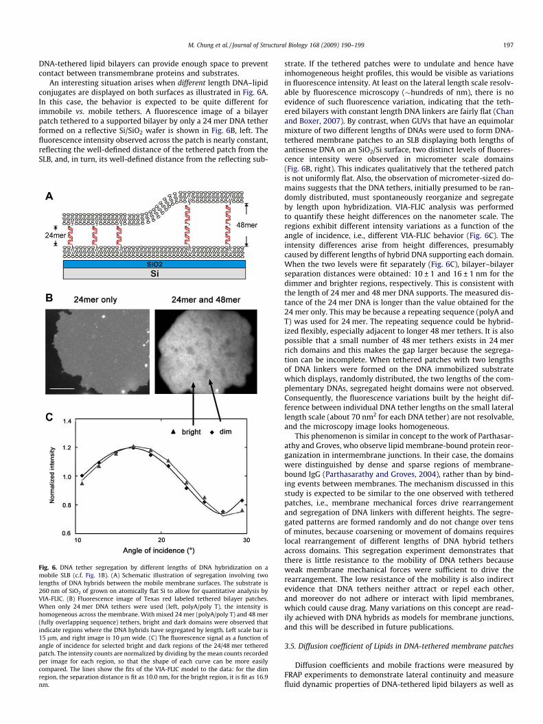
An interesting situation arises when different length DNA–lipidconjugates are displayed on both surfaces as illustrated in Fig. 6A.In this case, the behavior is expected to be quite different forimmobile vs. mobile tethers. A fluorescence image of a bilayerpatch tethered to a supported bilayer by only a 24 mer DNA tetherformed on a reflective Si/SiO2 wafer is shown in Fig. 6B, left. Thefluorescence intensity observed across the patch is nearly constant,reflecting the well-defined distance of the tethered patch from theSLB, and, in turn, its well-defined distance from the reflecting sub-
Fig. 6. DNA tether segregation by different lengths of DNA hybridization on amobile SLB (c.f. Fig. 1B). (A) Schematic illustration of segregation involving twolengths of DNA hybrids between the mobile membrane surfaces. The substrate is260 nm of SiO2 of grown on atomically flat Si to allow for quantitative analysis byVIA-FLIC. (B) Fluorescence image of Texas red labeled tethered bilayer patches.When only 24 mer DNA tethers were used (left, polyA/poly T), the intensity ishomogeneous across the membrane. With mixed 24 mer (polyA/poly T) and 48 mer(fully overlapping sequence) tethers, bright and dark domains were observed thatindicate regions where the DNA hybrids have segregated by length. Left scale bar is15 lm, and right image is 10 lm wide. (C) The fluorescence signal as a function ofangle of incidence for selected bright and dark regions of the 24/48 mer tetheredpatch. The intensity counts are normalized by dividing by the mean counts recordedper image for each region, so that the shape of each curve can be more easilycompared. The lines show the fits of the VIA-FLIC model to the data: for the dimregion, the separation distance is fit as 10.0 nm, for the bright region, it is fit as 16.9nm.
strate. If the tethered patches were to undulate and hence haveinhomogeneous height profiles, this would be visible as variationsin fluorescence intensity. At least on the lateral length scale resolv-able by fluorescence microscopy (�hundreds of nm), there is noevidence of such fluorescence variation, indicating that the teth-ered bilayers with constant length DNA linkers are fairly flat (Chanand Boxer, 2007). By contrast, when GUVs that have an equimolarmixture of two different lengths of DNAs were used to form DNA-tethered membrane patches to an SLB displaying both lengths ofantisense DNA on an SiO2/Si surface, two distinct levels of fluores-cence intensity were observed in micrometer scale domains(Fig. 6B, right). This indicates qualitatively that the tethered patchis not uniformly flat. Also, the observation of micrometer-sized do-mains suggests that the DNA tethers, initially presumed to be ran-domly distributed, must spontaneously reorganize and segregateby length upon hybridization. VIA-FLIC analysis was performedto quantify these height differences on the nanometer scale. Theregions exhibit different intensity variations as a function of theangle of incidence, i.e., different VIA-FLIC behavior (Fig. 6C). Theintensity differences arise from height differences, presumablycaused by different lengths of hybrid DNA supporting each domain.When the two levels were fit separately (Fig. 6C), bilayer–bilayerseparation distances were obtained: 10 ± 1 and 16 ± 1 nm for thedimmer and brighter regions, respectively. This is consistent withthe length of 24 mer and 48 mer DNA supports. The measured dis-tance of the 24 mer DNA is longer than the value obtained for the24 mer only. This may be because a repeating sequence (polyA andT) was used for 24 mer. The repeating sequence could be hybrid-ized flexibly, especially adjacent to longer 48 mer tethers. It is alsopossible that a small number of 48 mer tethers exists in 24 merrich domains and this makes the gap larger because the segrega-tion can be incomplete. When tethered patches with two lengthsof DNA linkers were formed on the DNA immobilized substratewhich displays, randomly distributed, the two lengths of the com-plementary DNAs, segregated height domains were not observed.Consequently, the fluorescence variations built by the height dif-ference between individual DNA tether lengths on the small laterallength scale (about 70 nm2 for each DNA tether) are not resolvable,and the microscopy image looks homogeneous.
This phenomenon is similar in concept to the work of Parthasar-athy and Groves, who observe lipid membrane-bound protein reor-ganization in intermembrane junctions. In their case, the domainswere distinguished by dense and sparse regions of membrane-bound IgG (Parthasarathy and Groves, 2004), rather than by bind-ing events between membranes. The mechanism discussed in thisstudy is expected to be similar to the one observed with tetheredpatches, i.e., membrane mechanical forces drive rearrangementand segregation of DNA linkers with different heights. The segre-gated patterns are formed randomly and do not change over tensof minutes, because coarsening or movement of domains requireslocal rearrangement of different lengths of DNA hybrid tethersacross domains. This segregation experiment demonstrates thatthere is little resistance to the mobility of DNA tethers becauseweak membrane mechanical forces were sufficient to drive therearrangement. The low resistance of the mobility is also indirectevidence that DNA tethers neither attract or repel each other,and moreover do not adhere or interact with lipid membranes,which could cause drag. Many variations on this concept are read-ily achieved with DNA hybrids as models for membrane junctions,and this will be described in future publications.
3.5. Diffusion coefficient of Lipids in DNA-tethered membrane patches
Diffusion coefficients and mobile fractions were measured byFRAP experiments to demonstrate lateral continuity and measurefluid dynamic properties of DNA-tethered lipid bilayers as well as

Fig. 7. FRAP analysis of lipid mobility in tethered membrane patches. (A) Theimages show a representative example of recovery after photo-bleaching of 4 lmbleached spot (left) in a fluorescently labeled DNA-tethered membrane patch. Thisis on the immobilized DNA tethers as Fig. 1A. Scale bar is 5 lm. (B) Circularaveraged radial profile (dots) from the center of bleached spot is generated from theinitial intensity profile after bleaching, I(r, t = 0), to reduce noise. K and w values(see Section 2) from a fit to a Gaussian function (line) are used for plotting graph C.(C) Representative normalized fluorescence intensity recovery curve (dots) ofbleached spot is plotted. This is fitted to obtain diffusion coefficient and mobilefraction (line). The first six data points are intensities before bleaching.
198 M. Chung et al. / Journal of Structural Biology 168 (2009) 190–199
measure diffusion coefficients of lipid molecules. Fig. 7 shows thespot-bleaching recovery region of a tethered membrane patchand the normalized fluorescence intensity recovery curve. Diffu-sion coefficients and mobile fractions of DNA-tethered membranepatches, SLBs formed by GUVs, and SLBs are summarized in Table1. The values (3.4 lm2 s�1) of SLB diffusion coefficients are some-what higher than most reports (Wagner and Tamm, 2000; Nau-mann et al., 2002; Renner et al., 2008), which were between 0.5and 2.5 lm2 s�1 for SLBs composed of synthetic PCs on glass pre-pared in a similar process. This difference is possibly because theseinvestigators used the classical approach of Axelrod or Soumpasis(Axelrod et al., 1976; Soumpasis, 1983), which can cause signifi-cant underestimation of diffusion coefficients, especially for highlymobile molecules (Braga et al., 2004). The diffusion coefficientsmeasured for SLB patches on glass from GUV rupture (3.2 lm2 s�1)and from vesicle fusion (3.4 lm2 s�1) are almost the same, as dis-cussed above. Diffusion coefficients for lipids in patches with mo-bile tethers (4.8 lm2 s�1) are somewhat smaller than withimmobilized DNA tethers (6.5 lm2 s�1), so there is no evidencefor hindered diffusion due to immobile tethers. Relatively stablepatches with mobile tethers had to be chosen due to the instabilitydescribed above, and it is quite possible that this selected popula-
Table 1Diffusion coefficients and mobile fractions determined by FRAP for lipids in DNA-tethered bilayer pathces and solid supported bilayers.
Diffusion coefficient [lm2 s�1] Mobile fraction [%]
DNA-tethered patchon immobilized tether
6.5 ± 1.0 0.99 ± 0.01
DNA-tethered patchon mobile tether
4.8 ± 0.2 0.97 ± 0.03
SLB formed by GUVs 3.2 ± 0.4 0.93 ± 0.02SLB formed by vesicle fusion 3.4 ± 0.2 0.97 ± 0.03
tion could have biased properties, e.g., tethered patches with lowerdiffusion may be more stable. In contrast to most reports of teth-ered or polymer-supported lipid bilayers, almost no immobile frac-tion is observed for the DNA-tethered membrane patches,suggesting that this is a particularly good system for minimizinginteractions with the substrate.
Diffusion coefficients of the tethered membrane patches are1.5–2.0 times higher than SLBs without DNA tethers. This resultcorresponds to the case of free-standing bilayers in GUVs, whosediffusion coefficients are two times larger than SLBs (7.8 lm2 s�1
vs. 3.1 lm2 s�1 on glass) (Przybylo et al., 2006). Thus the DNA spac-ers provide an environment that is more similar to free-standingbilayers than solid supported bilayers.
In summary, two novel architectures have been developedbased on DNA lipid conjugates that we originally developed fortethering and fusing vesicles (Yoshina-Ishii and Boxer, 2003; Chanet al., 2009). Stable membrane patches are obtained when the DNAdisplayed on the surface is covalently fixed on the surface, whileunstable patches are obtained when the DNA is displayed on a fluidSLB. Thus far, we have not observed coalescence of the patches toform a continuous tethered bilayer in either architecture. The sta-ble patches should be useful for displaying membrane proteins in aplanar format that retains all the advantages of the planar geome-try, yet keeps the proteins away from the solid support. The unsta-ble patches exhibit interesting dynamics when multiple lengths ofDNA hybrids are present and this can only occur because the lipidanchors on both surfaces are mobile.
Note added in proof
Stable tethered membrane patches with the mobile tethers toSLB (Fig. 1B) design have now been made by using special lipidcompositions. This will be described in a separate publication.
Acknowledgments
This work was supported by National Institutes of Health GrantGM069630, the NSF Biophysics Program, and by the MRSECProgram of the NSF under award DMR-0213618 (CPIMA). P.V.G.was supported by a Benchmark Stanford Graduate fellowship andCenter for Probing the Nanoscale Graduate Prize fellowship.R.D.L. in the Chidsey group was supported by Helicos BioSciencesCorporation.
References
Ajo-Franklin, C.M., Ganesan, P.V., et al., 2005a. Variable incidence angle fluorescenceinterference contrast microscopy for z-imaging single objects. Biophys. J. 89 (4),2759–2769.
Ajo-Franklin, C.M., Kam, L., et al., 2001. High refractive index substrates forfluorescence microscopy of biological interfaces with high z contrast. Proc. Natl.Acad. Sci. USA 98 (24), 13643–13648.
Ajo-Franklin, C.M., Yoshina-Ishii, C., et al., 2005b. Probing the structure of supportedmembranes and tethered oligonucleotides by fluorescence interference contrastmicroscopy. Langmuir 21 (11), 4976–4983.
Ali, M.B., Bessueille, F., et al., 2008. Use of ultra-thin organic silane films for theimprovement of gold adhesion to the silicon dioxide wafers for (bio)sensorapplications. Mater. Sci. Eng. C 28, 628–632.
Axelrod, D., Koppel, D.E., et al., 1976. Mobility measurement by analysis offluorescence photobleaching recovery kinetics. Biophys. J. 16 (9), 1055–1069.
Braga, J., Desterro, J.M., et al., 2004. Intracellular macromolecular mobilitymeasured by fluorescence recovery after photobleaching with confocal laserscanning microscopes. Mol. Biol. Cell. 15 (10), 4749–4760.
Chan, Y.-H.M., van Lengerich, B., et al., 2008. Lipid-anchored DNA mediates vesiclefusion as observed by lipid and content mixing. Biointerphases 3 (2), FA17–FA21.
Chan, Y.-H.M., Boxer, S.G., 2007. Model membrane systems and their applications.Curr. Opin. Chem. Biol. 11 (6), 581–587.
Chan, Y.-H.M., van Lengerich, B., et al., 2009. Effects of linker sequences on vesiclefusion mediated by lipid-anchored DNA oligonucleotides. Proc. Natl. Acad. Sci.USA 106 (4), 979–984.

M. Chung et al. / Journal of Structural Biology 168 (2009) 190–199 199
Deverall, M.A., Gindl, E., et al., 2005. Membrane lateral mobility obstructed bypolymer-tethered lipids studied at the single molecule level. Biophys. J. 88 (3),1875–1886.
Fu, Y.S., Yu, S.J., 2001. Immobilization of homogeneous palladium(II) complexcatalysts on novel polysiloxanes with controllable solubility: importantimplications for the study of heterogeneous catalysis on silica surfaces.Angew. Chem. Int. Ed. Engl. 40 (2), 437–440.
Jonsson, P., Jonsson, M.P., et al., 2008. A method improving the accuracy offluorescence recovery after photobleaching analysis. Biophys. J. 95 (11), 5334–5348.
Kolb, H.C., Finn, M.G., et al., 2001. Click chemistry: diverse chemical function from afew good reactions. Angew. Chem. Int. Ed. Engl. 40 (11), 2004–2021.
Koper, I., 2007. Insulating tethered bilayer lipid membranes to study membraneproteins. Mol. Biosyst. 3 (10), 651–657.
Kunding, A., Stamou, D., 2006. Subnanometer actuation of a tethered lipid bilayermonitored with fluorescence resonance energy transfer. J. Am. Chem. Soc. 128(35), 11328–11329.
Kung, L.A., Kam, L., et al., 2000. Patterning hybrid surfaces of proteins and supportedlipid bilayers. Langmuir 16, 6773–6776.
Lambacher, A., Fromherz, P., 2002. Luminescence of dye molecules on oxidizedsilicon and fluorescence interference contrast microscopy of biomembranes. J.Optical Soc. Am. B 19 (6), 1435–1453.
Longo, M.L., Ly, H.V., 2007. Micropipet aspiration for measuring elastic properties oflipid bilayers. Methods Mol. Biol. 400, 421–437.
Merzlyakov, M., Li, E., et al., 2006. Surface-supported bilayers with transmembraneproteins: role of the polymer cushion revisited. Langmuir 22 (24), 10145–10151.
Naumann, C.A., Prucker, O., et al., 2002. The polymer-supported phospholipidbilayer: tethering as a new approach to substrate-membrane stabilization.Biomacromolecules 3 (1), 27–35.
Naumann, R., Schiller, S.M., et al., 2003. Tethered lipid bilayers on ultraflat goldsurfaces. Langmuir 19, 5435–5443.
Parthasarathy, R., Groves, J.T., 2004. Protein patterns at lipid bilayer junctions. Proc.Natl. Acad. Sci. USA 101 (35), 12798–12803.
Phair, R.D., Misteli, T., 2000. High mobility of proteins in the mammalian cellnucleus. Nature 404 (6778), 604–609.
Popat, K.C., Sharma, S., et al., 2003. AFM analysis of organic silane thin films forbioMEMS applications. Surf. Interface Anal. 35, 205–215.
Przybylo, M., Sykora, J., et al., 2006. Lipid diffusion in giant unilamellar vesicles ismore than 2 times faster than in supported phospholipid bilayers underidentical conditions. Langmuir 22 (22), 9096–9099.
Purrucker, O., Fortig, A., et al., 2004. Supported membranes with well-definedpolymer tethers – incorporation of cell receptors. Chemphyschem 5 (3), 327–335.
Renner, L., Osaki, T., et al., 2008. Supported lipid bilayers on spacious and pH-responsive polymer cushions with varied hydrophilicity. J. Phys. Chem. B 112(20), 6373–6378.
Richter, R.P., Berat, R., et al., 2006. Formation of solid-supported lipid bilayers: anintegrated view. Langmuir 22 (8), 3497–3505.
Rossetti, F.F., Bally, M., et al., 2005. Interactions between titanium dioxide andphosphatidyl serine-containing liposomes: formation and patterning ofsupported phospholipid bilayers on the surface of a medically relevantmaterial. Langmuir 21 (14), 6443–6450.
Sackmann, E., 1996. Supported membranes: scientific and practical applications.Science 271 (5245), 43–48.
Saurel, O., Cezanne, L., et al., 1998. Influence of annexin V on the structure anddynamics of phosphatidylcholine/phosphatidylserine bilayers: a fluorescenceand NMR study. Biochemistry 37 (5), 1403–1410.
Seu, K.J., Pandey, A.P., et al., 2007. Effect of surface treatment on diffusion anddomain formation in supported lipid bilayers. Biophys. J. 92 (7), 2445–2450.
Soumpasis, D.M., 1983. Theoretical analysis of fluorescence photobleachingrecovery experiments. Biophys. J. 41 (1), 95–97.
Stadler, B., Falconnet, D., et al., 2004. Micropatterning of DNA-tagged vesicles.Langmuir 20 (26), 11348–11354.
Sund, S.E., Swanson, J.A., et al., 1999. Cell membrane orientation visualized bypolarized total internal reflection fluorescence. Biophys. J. 77 (4), 2266–2283.
Wagner, M.L., Tamm, L.K., 2000. Tethered polymer-supported planar lipid bilayersfor reconstitution of integral membrane proteins: silane–polyethyleneglycol–lipid as a cushion and covalent linker. Biophys. J. 79 (3), 1400–1414.
Wasserman, S.R., Tao, Y.-T., et al., 1989. Structure and reactivity of alkylsiloxanemonolayers formed by reaction of alkyltrichlorosilanes on silicon substrates.Langmuir 5 (4), 1074–1087.
Wong, A.P., Groves, J.T., 2002. Molecular topography imaging by intermembranefluorescence resonance energy transfer. Proc. Natl. Acad. Sci. USA 99 (22),14147–14152.
Yoshina-Ishii, C., Boxer, S.G., 2003. Arrays of mobile tethered vesicles on supportedlipid bilayers. J. Am. Chem. Soc. 125 (13), 3696–3697.
Yoshina-Ishii, C., Chan, Y.-H.M., et al., 2006. Diffusive dynamics of vesicles tethered to afluid supported bilayer by single-particle tracking. Langmuir 22 (13), 5682–5689.
Yoshina-Ishii, C., Miller, G.P., et al., 2005. General method for modification ofliposomes for encoded assembly on supported bilayers. J. Am. Chem. Soc. 127(5), 1356–1357.


![Boxer Engine[101]](https://img.pdfslide.us/doc/110x75/552722bd4a795973118b4635/boxer-engine101.jpg)