Embed Size (px)
Citation preview

*Corresponding author, e-mail: [email protected]
Research Article GU J Sci 34 (1): 112-126 (2021) DOI: 10.35378 gujs.698272
Gazi University
Journal of Science
http://dergipark.gov.tr/gujs
Implementation of Adaptive Neuro Fuzzy Controller for Fuel Cell Based
Electric Vehicles
K. Harshavardhana REDDY1,* , Sachin SHARMA1 , K. Shivarama KRISHNA2
1Department of ECE, East Point College of Engineering & Technology, Bengaluru, India
2Department of EEE, J.B Insitute of Engineering & Technology, Hyderabad, India
Highlights • Designed the Adaptive Neuro Fuzzy system based soft computing controller.
• The Proposed method is implemented to control speed in EV’s.
• The ANFIS based soft computing technique is compared with various existing methods.
Article Info
Abstract
The global concern for clean energy generation paved the way for technological inventions and
provided scope for researchers. More prominently, integration of heterogeneous renewable
sources, storage systems, and electric vehicles became the pioneer solutions. In this article, a soft
computing based ANFIS method has been proposed to execute the rapid speed response in electric
vehicle. Here, Brushless DC motor was used as a propulsion system to drive the vehicle. Electric
Vehicle is basically a time variant system, whose operating parameters and road conditions vary
continuously. To address these uncertainties, a novel control strategy is proposed. The fuel cell
battery is used as the auxiliary power supply for the electric vehicle. To demonstrate the
performance of the controllers, a case study has been considered with parameter uncertainties for
an ECE-15 test cycle. To evaluate the proficiency of the proposed soft computing control method,
the speed response results are evaluated and compared with existing methods like conventional
PI and fuzzy based tuned PID controllers. In addition, the performance of proposed technique is
benchmarked with other controllers reported in the literature.
Received: 03/03/2020 Accepted: 11/06/2020
Keywords
Electric vehicle
BLDC motor Speed control
Fuzzy PID controller
ANFIS controller
1. INTRODUCTION
In Now days, saving of electric energy has attracted a lot of researchers due to continuous exhaustion of
fossil elements and rapid rise in greenhouse gas emissions. Because of this, there is growing interest among
researchers to concentrate on technologies related to energy savings [1]. Taking this into account, the
automobile industry has focused on alternative energy sources other than petrol or diesel for fueling vehicles
which resulted in the usage of electric vehicles. Therefore, the development of Electric Vehicles (EVs) is
taking a quick pace in marketing.
The EVs have certain advantages like low weight, low CO2 emissions, easy cooling, excellent speed-torque
characteristics, low protection cost, high reliability, simple drive train systems and high-energy conversion
efficiency. Configuration of EVs is more flexible compared to Internal Combustion Engine Vehicles
(ICEVs) [2]. Some of the applications are implementation in short-range transportations, motorized
wheelchairs, and patrolling vehicles. In future EVs can be preferred for public transportations [3].
Generally, EVs consists of five parts: Electric motor, control system, batteries, bodywork, and charger. The
performances of the EVs rely on three factors. They are energy source, vehicle expectation, and constraints
[3-5]. In electric propulsion system Permanent Magnet (PM), brushless (BLDC) motors and induction
motors are mostly used [6]. The Brush less DC motor is explained as synchronous motor have trapezoidal
back EMF, which is used broadly in numerous applications like robotics, chemical industries, aeronautics,
113 K. Harshavardhana REDDY et al. / GU J Sci, 34 (1): 112-126 (2021)
and electric vehicles. etc. Since they require no mechanical commutators, it would have certain amenities
such as easier control, high power density, produce require torque and more efficiency [7].
In this paper, EVs, which consist of BLDC motors are considered for the study. In EVs, the controller plays
a crucial role to obtain the maximum accelerated performance. Because EV’s run on different road
conditions and also the operating parameters always variable in nature [8, 9]. Therefore, control of EV’s
become a key topic of research in the recent past [10]. Ziegler- Nichols [11] first implemented the PI/PID
controller tuning. In process industries, chemical industries, and also various electrical control applications
PI/PID controllers are used because it is easy to design [12].
In [13] PID controller is applied to control an electric wheelchair. For nonlinear and complex systems of
EVs, the PI/PID controllers do not give optimal performance. In [14] a hybrid PID controller applied for
the nonlinear system is proposed. This hybrid controller is resulted by swapping the normal PI controller
with two normalized fuzzy logic controller one for proportional gain and another one is for incremental
gain where the derivative gain is accounted as incremental gain. In control applications like temperature
process, industrial conveyor, and renewable applications these fuzzy logic controllers (FLCs) are used [15-
17]. The fuzzy logic controller is convenient to apply for electric vehicles [18] because EVs operate at
complex conditions. To provide high starting torque for the EVs at higher efficiency and speed tracking,
the fuzzy logic controller is implemented [19] using DSP embedded PID controller.
The authors in [20], have designed a robust and optimal controller to control motor in EV. A Linear
Quadratic Regulator (LQR) and differential geometric approach has been implemented. In addition the
robust controller gives better performance under uncertainties of EV operations. The demerit of the
controller is that the selection of LQR weight matrixes is difficult. In [21] the authors have implemented a
control for regenerative braking of EVs considering parametric variation and uncertainties using the robust
H- controller. Recently, an electric vehicle using type 2 fuzzy PI controller and the T-S model predictive
controller is proposed [22, 23]. In [24], PI and FLC are used to improve the engine power in hybrid electric
vehicles. But this controller gives more settling time and overshoot.
A control technique called ANFIS controller is used in numerous applications such as maximum power
extraction in solar panels and inertia control of wind turbines [25, 26], silicone rubber mechanical properties
approximation [27], robotic gripper control [28], human musculoskeletal arm [29], anti-lock braking system
[30], underwater vehicles [31], control of nonlinear industrial process and batch process [32, 33], estimation
of system forecasting [34], estimation of open lens system parameters [35].
In [36, 37], ANFIS controller is used for speed control of permanent magnet excitation transverse flux
linear motor and BLDC motor. This ANFIS gives satisfactory performance under load varying conditions.
In [38], a fuzzy PID supervised ANFIS controller is proposed for BLDC type motors. The recursive least
square back propagation algorithm is used to train the ANFIS system. In this work an ANFIS controller has
been implemented for speed control of EVs. In this controller, the training data for the ANFIS is obtained
from the performance of fuzzy PID controller. The proposed controller has certain advantage that it gives
better performance in uncertain conditions also. The simulation results prove that the proposed method is
superior to the PI and fuzzy PID controller. The structure of the paper is as follows, section 1 explains the
introduction and literature survey, the design of EV is presented in section 2 and section 3 deals with the
implementation of ANFIS controller for EV. In section 4 results and discussions are presented. In section
5 conclusion of work is described.
2. EV SYSTEM MODEL
The vehicle and motor dynamics are two significant parts of EVs model which is shown in Figure 1.

114 K. Harshavardhana REDDY et al. / GU J Sci, 34 (1): 112-126 (2021)
Transmission
Unit
Vehicle
Dynamics
Motor and its
Controller
Figure 1. EV System Model
2.1. Vehicle Dynamics
A In the modeling of EVs dynamics, the factors considered to design road condition are hill climbing,
acceleration and aerodynamic drag etc. After considering these parameters, the model is represented as
shown in Equation (1) [39]
dt
dvmsinmgvAC
2
1mgF 2
drr +++= (1)
where g represents acceleration gravity, v represents vehicle driving velocity, μ_rr represents coefficient of
rolling resistance, ρ represents air density, A represents frontal area, Cd the drag coefficient and ∅ is the
hill climbing angle.
In Equation (1), the first, second, third and fourth term are given as rolling resistance force, aerodynamic
drag force, hill climbing force and acceleration force respectively. The following equation shows the
relationship between the force F that produced a counteractive torque to the driving motor which is given
as in Equation (2)
G
r.FTL = (2)
where r represents radius of tyre in (m) of the EV, G indicates gearing ratio and TL represents torque in
(Nm) and F is total force.
2.2. Motor Model
The BLDC motor diagram is shown in the Figure 2. The equation for line to line voltage are given in
Equation (3)
[
𝑣𝑎𝑏
𝑣𝑏𝑐
𝑣𝑐𝑎
]= [
𝑅𝑛 −𝑅𝑛 00 𝑅𝑛 −𝑅𝑛
−𝑅𝑛 0 𝑅𝑛
] [
𝑖𝑎𝑖𝑏𝑖𝑐
]+[
𝐿𝑛 −𝐿𝑛 00 𝐿𝑛 −𝐿𝑛
−𝐿𝑛 0 𝐿𝑛
]
[ 𝑑𝑖𝑎
𝑑𝑡𝑑𝑖𝑏
𝑑𝑡𝑑𝑖𝑐
𝑑𝑡 ]
+[
𝑒𝑎 − 𝑒𝑏
𝑒𝑏 − 𝑒𝑐
𝑒𝑐 − 𝑒𝑎
] (3)
where, Rn is the resistance of stator Windings in ohms, Ln and M represents the Self Inductance and mutual
inductance respectively and ea, eb and ec are emf. Vabc represents the phase voltages, iabc as phase currents.
The number of poles in the rotor are given in P.
The Te of the BLDC motor is shown in below Equation (4)
dt
dθw;)/wieiei(eT r
llccbbaaa =++= (4)
where, w1, 𝜃𝑟 represents the rotor position, angular velocity (rad/s), respectively.
The Te is employed to subdue the opposing torques of load and inertia, it is given in Equation (5)
115 K. Harshavardhana REDDY et al. / GU J Sci, 34 (1): 112-126 (2021)
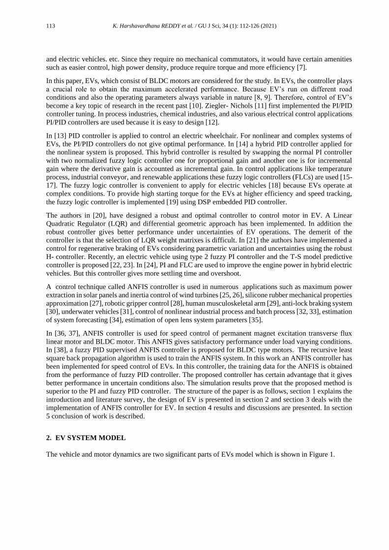
Figure 2. Stator winding of BLDC Motor
wBdt
dwJTT nnLa ++= (5)
where TL represents load torque (Nm), Jn is Momentum of Inertia (J or kg/m2), Bn indicates Friction
coefficient.
The BLDC motor advantages, with respect to other motors are lower electromagnetic interference (EMI),
lower maintenance costs and higher reliability [39, 40]. Then the overall block diagram to simulate the
electric vehicle is depicted in Figure 3. It comprises of a fuel cell battery to supply the power using DC-DC
converter and inverter and the electric motor is connected to EV [41-45].
Bidirection
al DC-DC
Converter
InverterElectric
Motor
AC
Eletricity
Mechanical
Transfer
EV
Tyres
Charger
Fuel cell
Battery
Figure 3. Block diagram representation of Electric Vehicle
The Figure 4 describes the speed control brushless DC motor using the adaptive neuro fuzzy
interface system, Fuzzy PID and PI Controller. The above circuit has a closed loop system to
control the speed of the BLDC motor, the speed of the BLDC motor controlled by the dc bus
voltage through pulse width modulation based voltage inverter. The control signal and the
switching logic is given to the three phase PWM volt age inverter, the feedback error signal
generate through the output of the brushless DC motor and the reference speed of the BLDC motor
is given to controller block.
R
R
R
Ua
Ub
Uc
L-M
L-M
L-M
ia
ib
ic

116 K. Harshavardhana REDDY et al. / GU J Sci, 34 (1): 112-126 (2021)
Figure 4. Simulation Model for Speed Controller of BLDC Motor in EVs
3. SPEED CONTROL TECHNIQUES FOR ELECTRIC VEHICLES
To control the speed of EV, ANFIS controller is proposed and in order to analyze the betterment of the
proposed method it is compared with the conventional PI and Fuzzy PID controller.
3.1. PI Controller Design
There are two variables in PI Controller commonly known as proportional gain Kp and integral gain Ki for
which the transfer function is given in Equation (6)
s
kk)s(X i
p += . (6)
In order to design the PI controller in Electric Vehicle System with control on speed, the two controller
gains are considered as state variables. which are stated in Equation (7)
+= dt)t(xk)t(xk)t(u ip . (7)
The Tuning of proponational gain and Integral gain of PI Controller is governed by the Ziegler- Nichols
method.[11]. So for the speed control in EV system the obtained kp is 0.013 and Integral gain ki is 12.
3.2. Fuzzy PID Controller design
Rate of change of error and error are the two inputs for the fuzzy interface system for which the block
diagram is demonstrated in Figure 5. Outputs and inputs both have seven trigonal membership functions
and the input ranges between [-0.5 to 0.5] for both input and output. The distribution of the members has
seven functions smal lpositive, medium positive and big positive,zero, big negative, medium negative,
negative small. The membership functions distribution is as shown in the Figure 6.
Centroid method gives defuzzification of these fuzzy sets which is also called as the area centric or gravity
cetric. The defuzzification formula is stated in Equation (8)
𝑥 = ∫𝑉𝑐 (𝑥). 𝑧 𝑑𝑧/ ∫𝑉𝑐 (𝑥) 𝑑𝑥. (8)
For the tuning of the fuzzy based PID forty nine rules are used, and some of the examples of these rules are
as given below.
Output is big negative if change in error is big negative and error is zero.
Output is medium negative if change in error is medium negative and error is zero.
Output is small negative if change in error is small negative and error is zero.
Three Phase
Voltage PWM
Inverter
Three Phase
V-I
Measurement
BLDC
Motor
Hall
Signals
Rotor
Speed
Switching
Logic
ANFIS
controller,
Fuzzy PID
controller and
PI controller
d/dt
e
Actual Speed
Reference
Speed
+-

117 K. Harshavardhana REDDY et al. / GU J Sci, 34 (1): 112-126 (2021)
Where the integration represents the Algebraic integration of the membership functions. The gains used
for the BLDC motor to tune fuzzy PID controller is α, β. The values of α and β is 0.00169 and 48
respectively. Integrator gain is approximated as 48 and derivative gain as 0.8.
Figure 5. Mamdani FIS
Figure 6. Membership functions of inputs and outputs for proposed controller
3.3. Adaptive Neuro Fuzzy Controller
It is mixture of ANN with fuzzy interface system. The Takagi - Sugeno model is used in this proposed work
[46]. ANFIS is a very good learning technique to take over an issue on uncertainties in any system. This
controller is based on framing fuzzy IF-Then rules that produces specific input-output with the help of
membership functions. The learning process of ANFIS consists of three stages; first is the rule base, second
is the membership functions and the third is the reasoning mechanism [35, 39].
Consider the set of fuzzy rules;
Let Rj= If x1 is A1(x1) and x2 is A2j(x2) and .......xn is Anj (xn) THEN y is cj
where,
x1 = change in error given as wref- wr.
x2= derivative of change in error given as d(wref- wr)/dt.
y = output given as Pix1+Rix2+Si
A1(x1) and Anj (xn)......... Anj (xn) are input linguistic labels and cjis constant consequent labels.
In TS Fuzzy model, to find the conclusion for input X an inference procedure is implemented, which is
listed in two steps as given below.
The weight of wj in each rule is calculated as shown in Equation (9)
)(
1
0=
=
n
i
iijj xw (9)
where wj is weights of each rule, µij is linguistic label.
Error Data
Change in
Error Data
Fuzzy PID
Control
System
Output Data
Fuzzification
BlockRule Base Block Defuzzification
Block
-0.5 0.5-0.5
1Member Ship Functions

118 K. Harshavardhana REDDY et al. / GU J Sci, 34 (1): 112-126 (2021)
The output inference result y is obtained by means of the weighted average of the consequents in Equation
(10)
=
==
m
j
j
m
j
jj
w
cw
y
1
1 (10)
where, y is output, wj is weights, and cj is constant consequent labels.
Equations (9) and (10) provides the complete representation of the inference model.
The Architecture of ANFIS network consists of different types of inference models as adaptive networks.
The adaptive network consists of following layers as shown in Figure 7. The layer 1 having m groups and
having n nodes of each one.
Every single node generates output by solving each membership function as shown in Equation (11)
.....),;()( 2100)1(
jijiiijij ppxfxk == (11)
where kij is the outputs of the nodes.
The 2nd layer represents the precondition of the fuzzy rule and is denoted by ‘π’ which is multiplied with
the signals to get output as shown in Equation (12)
j
n
i
ijj wkk ===1
)1()2(. (12)
The layer 3 consists of an m – nodes normalization layer. The output of the jth node )4(jk is the ratio of the
jth rules of weight to the sum of all the rules as Equation (13)
yckk j
m
j
jj ===1
)3()4(. (13)
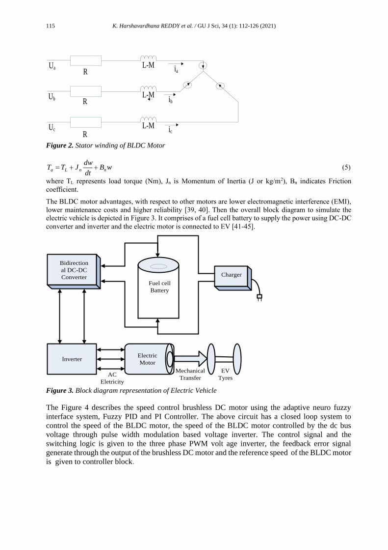
Figure 7. Architecture of an n – input adaptive neuro fuzzy controller [39]
For the proposed controller the data of error and change in error of fuzzy PID plus PD controller data set is
used. The structure of adaptive fuzzy controller, generated by the MATLAB code is a five layer network as
shown in Figure 8.
(Q1,n , Q2,n-----)
(Q1,n , Q2,n-----)
X1n
Xjn
Xnn
K1,1(1)
K2,1(1)
Kn,i(1)
K1,2(1)
K2,2(1)
Kn,j(1)
K1,3(1)
K2,3(1)
Kn,m(1)
π
π
π
N
N
N
ε
K1(2)
Ki(2)
Km(2)
K1(3)
Ki(3)
Km(3)
B1
Bj
Bm
K(4)= y
119 K. Harshavardhana REDDY et al. / GU J Sci, 34 (1): 112-126 (2021)
It has two inputs (error and change in error), one output and three membership functions.
Figure 8. Structure for ANFIS controller [39]
The Figure 9 shows the output of fuzzy rule for a specific value of change in error and error.
Figure 9. ANFIS Controller Rules
4. SIMULATION RESULTS
The proposed controller performance for the EV is studied and its efficiency is evaluated based on the
obtained results that are compared with conventional controller. The Vehicle parameters are taken from
[20] and are listed in Table 1.
4.1. Case 1
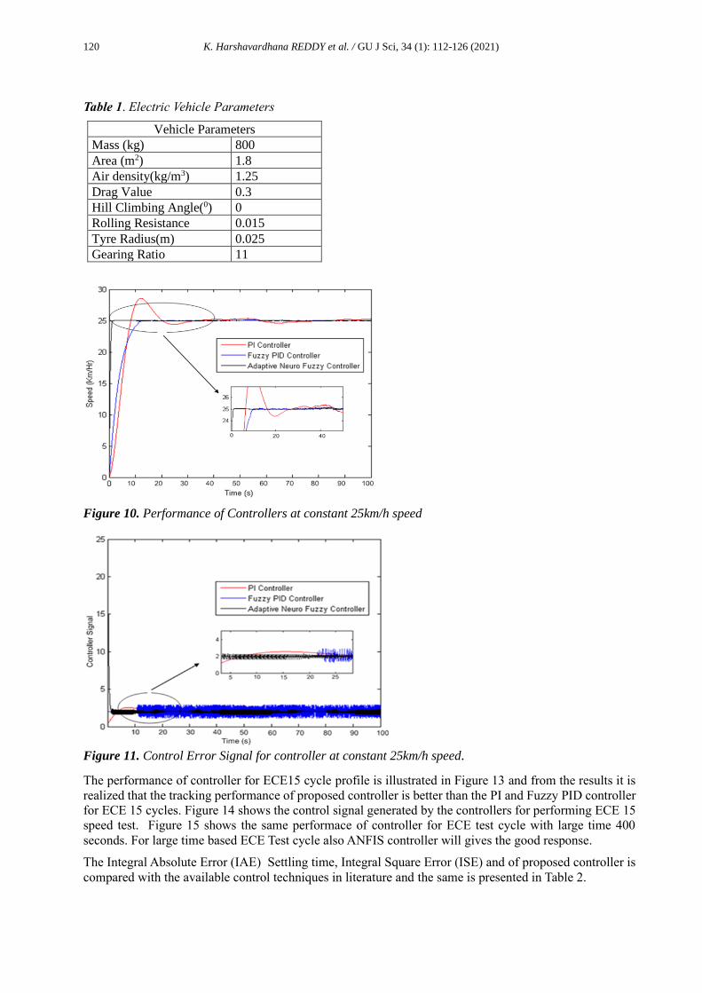
Case 1 deals with the performance of the controllers at constant speed when operating at 25 Km/h. The
proposed controllerand its performance is compared with existing controllers illustrated in Figure 10. It is
realized that the proposed control method achieves enhanced response in shorter time. The control signal
of control method is in Figure 11, from this it can be observed that the proposed control method based
ANFIS has achieved enhanced performance using less control energy.
4.2. Case 2
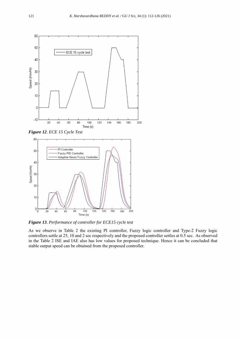
In case 2, an ECE 15 cycle is used to validate the speed control of EVs for the proposed controller. The
ECE 15 cycle profile obtained for a speed of 50 km/h is shown in Figure 12.
120 K. Harshavardhana REDDY et al. / GU J Sci, 34 (1): 112-126 (2021)
Table 1. Electric Vehicle Parameters
Vehicle Parameters
Mass (kg) 800
Area (m2) 1.8
Air density(kg/m3) 1.25
Drag Value 0.3
Hill Climbing Angle(0) 0
Rolling Resistance 0.015
Tyre Radius(m) 0.025
Gearing Ratio 11
Figure 10. Performance of Controllers at constant 25km/h speed
Figure 11. Control Error Signal for controller at constant 25km/h speed.
The performance of controller for ECE15 cycle profile is illustrated in Figure 13 and from the results it is
realized that the tracking performance of proposed controller is better than the PI and Fuzzy PID controller
for ECE 15 cycles. Figure 14 shows the control signal generated by the controllers for performing ECE 15
speed test. Figure 15 shows the same performace of controller for ECE test cycle with large time 400
seconds. For large time based ECE Test cycle also ANFIS controller will gives the good response.
The Integral Absolute Error (IAE) Settling time, Integral Square Error (ISE) and of proposed controller is
compared with the available control techniques in literature and the same is presented in Table 2.
121 K. Harshavardhana REDDY et al. / GU J Sci, 34 (1): 112-126 (2021)
Figure 12. ECE 15 Cycle Test
Figure 13. Performance of controller for ECE15 cycle test
As we observe in Table 2 the existing PI controller, Fuzzy logic controller and Type-2 Fuzzy logic
controllers settle at 25, 10 and 2 sec respectively and the proposed controller settles at 0.5 sec. As observed
in the Table 2 ISE and IAE also has low values for proposed technique. Hence it can be concluded that
stable output speed can be obtained from the proposed controller.

122 K. Harshavardhana REDDY et al. / GU J Sci, 34 (1): 112-126 (2021)
Figure 14. Control error signal of controllers for ECE 15 cycle test
Table 2. Comparison table for performace of diffrent Controllers
Sl.no. Controllers Settling Time (Sec) ISE IAE
1 PI controller [24] 25 3564 9.189
2 Fuzzy Logic Controller[24] 10 3154 9.178
3 PI Controller – Type- 2
Fuzzy logic [22]
2 2978 8.828
4 Proposed Controller 0.5 2842 7.68
Figure 15. Peformane of controllers for ECE 15 cycle test with 400sec
5. CONCLUSION
In this work, an ANFIS is proposed for application of speed control in Electric Vehicles. The proposed
method is evaluated on various EVs under different conditions. The implementation of proposed control
strategy is easy and unsophisticated. To evaluate the robustness of the proposed method comparison has
been made with the conventional PI and fuzzy PID controllers. The proposed control strategy gives good
speed tracking performance than other controllers. The ECE 15 speed profile is used to validate the
controller. The presented controller is also validated under various operating conditions and it is decided
that it gives better task.
40 280 320 360 400
Time(sec)
0 80 120 160 200 240
10
20
30
40
50
50
Spee
d (K
mph
)
123 K. Harshavardhana REDDY et al. / GU J Sci, 34 (1): 112-126 (2021)
CONFLICTS OF INTEREST
No conflict of interest was declared by the authors.
REFERENCES
[1] Chan, C.C., “The state of the art of electric and hybrid vehicles”, Proc. IEEE, 90(2): 247–275, (2002).
[2] Leduc, P., Dubar, B., “Downsizing of gasoline engine: an efficient way to reduce CO2 emissions”. Oil
Gas Science Technology, 58: 115–27, (2003).
[3] Yang, Z., Shang, F., Brown, I. P., & Krishnamurthy, M., “Comparative study of interior permanent
magnet, induction, and switched reluctance motor drives for EV and HEV applications”. IEEE
Transactions on Transportation Electrification, 1(3): 245-254, (2015).
[4] Kim, K. C., “A novel magnetic flux weakening method of permanent magnet synchronous motor for
electric vehicles”, IEEE Transactions on Magnetics, 48(11): 4042-4045.
[5] Chan, C. C., Chau, K. T., Jiang, J. Z., Xia, W. A. X. W., Zhu, M., Zhang, R., “Novel permanent magnet
motor drives for electric vehicles”, IEEE Transactions on Industrial Electronics, 43(2): 331-339,
(1996).
[6] Wang, J., Atallah, K., Zhu, Z. Q., Howe, D., “Modular 3-phase permanent magnet brushless machines
for in-wheel applications”, IEEE Vehicle Power and Propulsion Conference,1-6, (2006).
[7] Konstantinos, L.,I., Kladas A.,G., “Internal permanent magnet motor design for electric vehicle drive”,
IEEE Transactions on Industrial Electronics, 57(1): 138-145,(2010).
[8] Mura, R., Vadim, U., Simona, O., “Energy management design in hybrid electric vehicles: A novel
optimality and stability framework”, IEEE Transactions on Control Systems Technology, 23(4): 1307-
1322, (2015).
[9] Overington, S., Sumedha, R., “High-efficiency control of internal combustion engines in blended
charge depletion/charge sustenance strategies for plug-in hybrid electric vehicles”, IEEE Transactions
on Vehicular Technology, 64(1): 48-64, (2015).
[10] Sharma, I., Shubhi, P., “Nonlinear controllers for a light-weigted all-electric vehicle using Chebyshev
neural network”, International Journal of Veicular Technology, (2014)
[11] Ziegler, I. G., Nicholas, N B., “Optimum settings for automatic controllers”. Trans. ASME, 64(11),
(1942).
[12] Ramanathan, P., Arjun A, Mampilly., K.J, Marimuthu R. Ramasamy S., “Study and comparison of
fuzzy logic and PI controller based on pressure control system”, International Review on Modeling
and Simulations, 5: 1356-1359,(2012).
[13] Brown, K., E., Rafael, Inigo R.,M., Johnson,B.W., “Design, implementation, and testing of an
adaptable optimal controller for an electric wheelchair”, IEEE Transactions on Industry Applications,
26 (6):1144-1157,(1990).
[14] Er, M. J., Sun, Y. L., “Hybrid fuzzy proportional-integral plus conventional derivative control of linear
and nonlinear systems”. IEEE Transactions on Industrial Electronics, 48(6),1109-1117, (2001).
[15] Kasa, S., Ramasamy, S., Ramanathan, P., “Hybrid fuzzy-ZN PID control based grid interfaced
distribution level renewable energy source with power quality”, International Conference on Circuits,
Power and Computing Technologie, 1-7, (2015).

124 K. Harshavardhana REDDY et al. / GU J Sci, 34 (1): 112-126 (2021)
[16] Ramanathan, P., Sukanya, K. C., Mishra, S., Ramasamy., “Study on Fuzzy Logic and PID Controller
for temperature regulation of a system with time delay”, International Conference on Energy Efficient
Technologies for Sustainability, 274-277, (2013).
[17] Srikar, S., B., Sarath K., M., Ramasamy, S., “Design and Implementation of fuzzy logic control based
speed control of Industrial conveyor”, ARPN Journal of Engineering and Applied Sciences, 9.(9):
1547-1553, (2014).
[18] Schouten, N. J., Salman, M. A., Kheir, N. A., “Fuzzy logic control for parallel hybrid vehicles”, IEEE
Transactions on Control Systems Technology, 10(3): 460-468, (2002).
[19] Wu, H. X., Cheng, S. K., Cui, S. M, “A controller of brushless DC motor for electric vehicle”, IEEE
Transactions on Magnetics, 41(1): 509-513, (2005).
[20] Huang, Q., Huang, Z., Zhou, H., “Nonlinear optimal and robust speed control for a light-weighted all-
electric vehicle”,IET Control Theory & Applications, 3(4): 437-444, (2009).
[21] Ye, M., Bai, Z., Cao, B., “Robust control for regenerative braking of battery electric vehicle”. IET
Control Theory & Applications, 2(12): 1105-1114, (2008).
[22] Khooban, M., H., Taher,N., Mokhtar S., “Speed control of electrical vehicles: A Time-Varying
Proportional–Integral Controller-based Type-2 Fuzzy Logic”, IET Science, Measurement &
Technology, 10(3): 185-192,(2016).
[23] Khooban, M., H., Navid,V., Taher,N., “T–S fuzzy model predictive speed control of electrical
vehicles”, ISA Transactions,(2016).
[24] Syed, F., U., Kuang, M.L., Smith,M., Okubo,S., Ying,H., “Fuzzy gain-scheduling proportional–
integral control for improving engine power and speed behavior in a hybrid electric vehicle”, IEEE
Transactions on Vehicular Technology, 58(1): 69-84,(2009).
[25] Petković, D., P., Cojbasic, Z., Nikolic.V.,Shamsirband,S., Kiah, M.L.M., Anur,N.B., Wahab, A.W.A.,
“Adaptive neuro-fuzzy maximal power extraction of wind turbine with continuously variable
Transmission” Energy, 64: 868-874,(2014).
[26] Hafiz, F., Abdennour, A., “An adaptive neuro-fuzzy inertia controller for variable-speed wind
turbines”. Renewable Energy, 92: 136-146, (2016).
[27] Petković, D., Issa, M., Pavlović, N. D., Pavlović, N. T., Zentner, L., “Adaptive neuro-fuzzy estimation
of conductive silicone rubber mechanical properties”. Expert Systems with Applications, 39(10):
9477-9482, (2012).
[28] Petković, D., Issa, M., Pavlović, N. D., Zentner, L., Ćojbašić, Ž., “Adaptive neuro fuzzy controller for
adaptive compliant robotic gripper”. Expert Systems with Applications, 39(18): 3295-13304,(2012).
[29] Vatankhah, R., Broushaki, M., Alasty, A., “Adaptive optimal multi-critic based neuro-fuzzy control
of MIMO human musculoskeletal arm model”. NeuroComputing, 173: 1529-1537, (2016).
[30] Topalov, A., Oniz, Y., Kayacan,E., Kayank, O., “Neuro-Fuzzy control of antilock braking system
using sliding mode inceremental learning alogorithm”,Neurocomputing, 74(11): 1883-1893,(2011).
[31] Liu, Y., Si-Yuan, L., Ning, W., “Fully-tuned fuzzy neural network based robust adaptive tracking
control of unmanned underwater vehicle with thruster dynamics”, Neuro Computing, 19(6): 1-13,
(2016).

125 K. Harshavardhana REDDY et al. / GU J Sci, 34 (1): 112-126 (2021)
[32] Sarhadi, P., Behrooz, R.., Zahra, R., “Adaptive predictive control based on adaptive neuro-fuzzy
inference system for a class of nonlinear industrial processes” Journal of the Taiwan Institute of
Chemical Engineers,132-137, (2015).
[33] Jia, Li., Kai, Yuan., “The probability density function based neuro-fuzzy model and its application in
batch processes”, Neurocomputing, 148: 216-221, (2015).
[34] Wang, W., De, Z. L., Joe, V., “An evolving neuro-fuzzy technique for system state forecasting”,
Neurocomputing, 87:111-119, (2012).
[35] Petković, D., Pavlovic, N.T., Samshirband, S., Kiah, M.L.M., Anuar, N.B., Idris, M.Y.I., “Adaptive
neuro-fuzzy estimation of optimal lens system parameters”, Optical Laser Engineering, 55: 84-93,
(2014).
[36] Hasanien, H., M., Muyeen S.,M., Junji, T., “Speed control of permanent magnet excitation transverse
flux linear motor by using adaptive neuro-fuzzy controller”, Energy Conversion Management, 51(12)
:2762-2768, (2012).
[37] Premkumar, K., B. V. Manikandan., “Adaptive Neuro-Fuzzy Inference System based speed controller
for brushless DC moto” Neuro Computing,138: 260-270, (2014).
[38] Premkumar, K., Manikandan B.V., “Fuzzy PID supervised online ANFIS based speed controller for
brushless dc motor”, Neuro Computing,157: 76-90, (2015).
[39] Reddy, K. H., Sudha, R., Prabhu, R., “Hybrid Adaptive Neuro Fuzzy based speed Controller for
Brushless DC Motor”. Gazi University Journal of Science, 30(1): 93-110, (2017).
[40] Ozturk, S., B., Hamid, A. Toliyat., “Direct torque and indirect flux control of brushless DC motor”
IEEE/ASME Transactions on Mechatronics,16(2): 351-360, (2011).
[41] Pillay, P., Ramu, K., “Modeling, simulation, and analysis of permanent-magnet motor drives. I. The
permanent-magnet synchronous motor drive”, IEEE Transactions on Industry Applications,25(2):
265-273, (1989).
[42] Alphonse, I., Hosimin, T., F. Bright, S., “Design of solar powered BLDC motor driven electric
vehicle”, International Journal of Renewable Energy Research (IJRER), 2(3): 456-462, (2012).
[43] Rekioua, T., Rekioua D., “Direct torque control strategy of permanent magnet synchronous
machines.” 2003 IEEE Bologna Power Tech Conference Proceedings, 2. IEEE, (2003).
[44] Tsotoulidis, S., N., Athanasios, N., S., “Analysis of a drive system in a fuel cell and battery powered
electric vehicle” International Journal of Renewable Energy Research (IJRER), 1(3): 140-151,(2011).
[45] Benmouna, A., Becherif, M., Depernet, D., Depature, C., Boulon, L., “Nonlinear control and
optimization of hybrid electrical vehicle under sources limitation constraints.” International Journal
of Hydrogen Energy 45(19): 11255-11266, (2020).
[46] Moshkbar-Bakhshayesh, K., Mohammad, B., G., “Development of an efficient identifier for nuclear
power plant transients based on latest advances of error back-propagation learning algorithm”, IEEE
Transactions on Nuclear Science, 61(1): 602-610, (2014).

126 K. Harshavardhana REDDY et al. / GU J Sci, 34 (1): 112-126 (2021)
Annexure:
Training Data For ANFIS
Error Change in Error Output Error Change in
Error
Output
1200 0 1003.34 32.85 731.14 115.03
1200 0 1003.34 28.17 -5806.14 112.36
1200 0 1003.31 24.17 -9601.01 110.18
1200 0 1003.30 20.63 478.91 108.20
1200 0 1003.26 17.76 -4189.22 106.69
1177.03 -459262.35 985.89 15.12 -6485.58 105.24
1137.66 -7.87393.83 956.13 13.13 304.43 104.28
1087.03 -1012622.02 917.87 11.21 -2214.92 103.24
1021.84 -1303851.99 868.61 9.93 1445.94 102.15
961.43 -1.208144.40 822.97 8.56 -169.47 101.62
905.20 -1124706.41 780.49 7.11 1397.58 100.92
852.59 -1052121.69 740.74 6.41 1374.57 100.08
791.64 -1219018.81 694.70 5.48 1057.71 99.91
736.87 -1095339.40 653.32 4.37 2551.54 99.48
677.19 -1193622.30 608.24 4.14 605.83 98.86
624.63 -1051222.06 568.54 3.57 3955.59 99.010
569.39 -1104819.03 526.81 2.75 453.97 98.83
521.28 -962119.89 490.47 2.94 5697.73 98.39
471.95 -986583.51 453.21 2.71 659.79 97.77
429.29 -853368.52 420.99 2.13 7796.14 98.12
386.34 -858968.93 388.55 1.30 1215.27 98.12
349.35 -739824.07 360.61 1.77 -4623.27 97.83
312.67 -733472.08 332.91 1.76 6742.87 98.35
281.17 -629954.66 309.12 0.36 -867.57 98.40
250.36 -616374.41 285.84 0.31 -7210.99 98.13
223.94 -528349.47 265.89 0.10 8305.18 98.49
198.40 -510790.82 246.60 0.12 -414.34 98.43
176.54 -437239.30 230.09 0.04 -7436.63 98.09
155.64 -417917.73 214.31 0.05 11886.66 97.57
136.09 -391039.60 199.54 0.03 1838.56 97.60
119.53 -331149.48 187.04 0.026 -6088.24 97.37
104.14 -307780.54 175.42 0.08 -12075.99 96.99
91.085 -261228.45 165.55 0.07 13711.11 97.02
79.05 -240632.68 156.47 0.21 3260.23 96.85
68.81 -6009.5311 148.74 0.20 22181.58 96.60
59.49 10007.6871 141.70 0.43 7617.90 96.81
51.53 -1024.97 135.68 0.82 -3037.30 96.52
44.38 -8451.18 130.29 0.57 12664.70 96.59


![Design features and research on the neuro-like learning ... · systems based on neuro-fuzzy logic: - an adaptive neuro-fuzzy inference system (ANFIS) [15]; - an adaptive neurofuzzy](https://img.pdfslide.us/doc/110x75/605ac52cb6bd5c4a7f031940/design-features-and-research-on-the-neuro-like-learning-systems-based-on-neuro-fuzzy.jpg)