Embed Size (px)
Citation preview
lable at ScienceDirect
Journal of Power Sources 294 (2015) 386e392
Contents lists avai
Journal of Power Sources
journal homepage: www.elsevier .com/locate/ jpowsour
Enhanced electrochemical performance of a crosslinked polyaniline-coated graphene oxide-sulfur composite for rechargeablelithiumesulfur batteries
San Moon, Young Hwa Jung, Do Kyung Kim*
Department of Materials Science and Engineering, KAIST, Daejeon 305-701, Republic of Korea
h i g h l i g h t s
� A uniform crosslinked PANI layer is fabricated on graphene oxide-sulfur composite.� The PANI layer is synthesized by the layer-by layer assembly technique with a heating.� The PANI layer plays a role as preventing the dissolution of polysulfides.� A crosslinking process shows superior electrochemical performance with a high sulfur contents.
a r t i c l e i n f o
Article history:Received 23 February 2015Received in revised form11 May 2015Accepted 2 June 2015Available online xxx
Keywords:SulfurBatteryConductive polymerCrosslinking
* Corresponding author.E-mail address: [email protected] (D.K. Kim).
http://dx.doi.org/10.1016/j.jpowsour.2015.06.0110378-7753/© 2015 Elsevier B.V. All rights reserved.
a b s t r a c t
Due to the extraordinarily high theoretical capacity of sulfur (1675 mAh g�1), the lithiumesulfur (LieS)battery has been considered a promising candidate for future high-energy battery applications. LieSbatteries, however, have suffered from limited cycle lives, mainly due to the formation of soluble poly-sulfides, which prevent the practical application of this attractive technology. The encapsulation of sulfurwith various conductive materials has addressed this issue to some extent. Nevertheless, most ap-proaches still present partial encapsulation of sulfur and moreover require a large quantity of conductivematerial (typically, >30 wt%), making the use of sulfur less desirable from the viewpoint of capacity. Here,we address these chronic issues of LieS cells by developing a graphene oxide-sulfur composite with athin crosslinked polyaniline (PANI) layer. Graphene oxide nanosheets with large surface area, highconductivity and a uniform conductive PANI layer, which are synthesized by a layer-by-layer method,have a synergetic interaction with a large portion of the sulfur in the active material. Furthermore, asimple crosslinking process efficiently prevents polysulfide dissolution, resulting in unprecedentedelectrochemical performance, evenwith a high sulfur content (~75%): a high capacity retention of ~80% isobserved, in addition to 97.53% of the average Coulombic efficiency being retained after 500 cycles. Theperformance we demonstrate represents an advance in the field of lithiumesulfur batteries for appli-cations such as power tools.
© 2015 Elsevier B.V. All rights reserved.
1. Introduction
As mobile devices deeply penetrate into our everyday lives, thedemand for high-energy rechargeable batteries is rapidlyincreasing [1e6]. Moreover, the utilization of rechargeable batte-ries has broadened their use to larger applications, such as electricvehicles and electrical grid systems, which require much higher
energy density. The current lithium-ion batteries (LIBs), however,which are based on traditional insertion oxide cathode materials(e.g., LiCoO2, LiMnO4 and LiFePO4) with limited capacitiesapproximately 100e200 mAh g�1, cannot fulfill the energy de-mands of new devices with high power because of their heavyweight and singleeelectron reaction [7,8]. Therefore, considerableattention has been devoted to alternative rechargeable batterysystems with significantly improved energy densities. Amongvarious candidates, the lithiumesulfur (LieS) battery is a prom-ising energy system with a high theoretical energy density(2500 Wh kg�1), which is approximately seven times larger than
S. Moon et al. / Journal of Power Sources 294 (2015) 386e392 387
those of the current LIBs (~387 Wh kg�1), and it utilizes theunparalleled theoretical capacity of sulfur (1675 mAh g�1) thatresults from the fact that sulfur is a light-weight element with atwo-electron reaction. As a cathode material, sulfur also has otheradvantages, such as nontoxicity, low cost and abundance of rawmaterials [9,10].
Despite the promise of sulfur, several challenges remainedunsolved, such as the insulating nature of sulfur (conductivity~10�30 S cm�1), its large volume expansion by up to 80% upon fulllithiation and its severe capacity fading during cycling [11e13].Sulfur, unlike insertion-based electrodes, undergoes a series ofstructural and morphological changes during cycling, includingthe formation of high-order lithium polysulfides (Li2Sn, 2 < n � 8)and low-order lithium polysulfides (Li2S2 and Li2S), which areinsulators. Additionally, the high-order lithium polysulfides aresoluble in the currently employed liquid electrolyte at the earlystage of discharge. The dissolution of high-order polysulfides re-sults in so-called shuttling effects: the dissolved polysulfidesdiffuse to the Li anode and are reduced, and then they diffuse backto the sulfur cathode. During this repeated round-trip of poly-sulfides, the active material is successively consumed, and the Limetal-electrolyte interface becomes unstable; both of thesephenomena play critical roles in the severe capacity decay[14e17]. Therefore, these problems should be addressed to enablethe utilization of lithiumesulfur batteries in practicalapplications.
One of the most popular approaches to resolve these issues hasbeen the encapsulation of sulfur in an electrically conductingmatrix, which enhances the electrical conductivity of the cathodeand prevents the dissolution of high-order polysulfides [18,19]. Inthis regard, various mesoporous carbon materials have beenstudied because they are expected to be effective at trapping high-order polysulfides due to their small pore diameters. Nevertheless,this type of cathode design does not completely prevent thedissolution of polysulfides because sulfur atoms remain at thesurface of the mesoporous carbon, which results in shuttling ef-fects. Several reports successfully solved this problem, but thesulfur contents in the electrode materials were too low, resultingin a loss of energy density in the battery. A thin, conductivecoating that has a high conductivity and good compatibility withsulfur minimizes the decrease in sulfur loading in the active ma-terial and is a good candidate for encapsulating sulfur. We previ-ously reported an encapsulated sulfur electrode that adopts asulfur nanowire array with a thin carbon coating, formed by usinganodic aluminum oxide (AAO) templates [20]. The completeencapsulation of sulfur, as well as the uncommon crystal structureof monoclinic phase resulting from the unique processing,demonstrated excellent electrochemical performance despite thehigh sulfur content. However, it is still necessary to overcome thecomplex processes and the limited electrode area. To addressthese issues, we report here a graphene oxide-sulfur compositewith a high sulfur content, which is encapsulated by theconductive polymer PANI. Diverse polymer coatings have beenemployed in previous studies [21e24], but standard polymercoatings have not been reported to show a noticeable ability toprevent polysulfide dissolution or maximize the effect of thepolymer.
In the present investigation, we fabricate a graphene oxide-sulfur composite with a crosslinked conductive polymer (polyani-line). The formation of the crosslinked-polymer shell in theGO_S@PANI composites enhanced the cycling stability, whichimproved the trapping of polysulfides and played a role in creatingbuffer layers against the volume changes of sulfur. This approachcould improve the overall electrochemical performance byresolving the aforementioned issues of lithiumesulfur batteries.
2. Experimental
2.1. Chemical and materials
Polyethyleneimine (PEI, Mw 50e100 kDa), poly(allylamine hy-drochloride) (PAH) (Mw 70 kDa), poly(styrenesulfonate sodiumsalt) (PSS) (Mw 70 kDa), glutaraldehyde (GA) aniline monomer andsulfur were purchased from SigmaeAldrich. All chemical reagentswere used without further purification.
2.2. Preparation of graphene oxide and sulfur composite (GO-S)
Graphene oxide (GO) was prepared using a modified Hummersmethod, as previously reported [25]. After washing and exfoliatingthe GO, the centrifuged GO was freeze-dried under vacuum for twodays. The graphene oxide (GO) and sulfur (weight ratio of 1:3) weremixed by ball-milling. The mixture was heated at 155 �C for 12 h ina closed vessel for sulfur infiltration.
2.3. Assembly of crosslinked PANI layer on the surface of composites
Graphene oxide-sulfur composites (GO-S) were separatelydispersed in a PEI solution (1 mg/ml in 0.5 M NaCl) and allowed toadsorb for 30 min. Then, excess polyelectrolyte was removed bycentrifugation and triplicate washing with 0.5 M NaCl. Subse-quently, the above suspensions were alternately dispersed in PAHand PSS solutions (2 mg/ml in 0.5 M NaCl) for another 30 min,followed by triplicatewashing in 0.5MNaCl. After the assembly of adesired number of PAH/PSS layers, the coated particles weredispersed in a 5% glutaraldehyde (GA) aqueous solution for 30 min.Finally, these sample suspensions were incubated at 70 �C for20 min. The prepared aqueous dispersion of polymer-coated sulfurparticles was added into the aniline monomer solution mixed with1 M hydrochloric acid (HCl) under stirring. After 30 min, theequivalent number of moles (with respect to aniline) of a 22.8 wt%aqueous ammonium persulfate (APS) solution was slowly added,followed by oxidative polymerization at 0 �C. The reaction durationwas 24 h. The resultant green solid, GO-S@PANI, was obtained bycentrifugation and washed with water and ethanol thoroughly toremove excess ions and monomers. The final product was driedunder vacuum at ambient temperature for 24 h. To crosslink thePANI layer, GO-S@PANI was heated at 180 �C for 1 h in air.
2.4. Characterization
The weight fractions of carbon and sulfur were determined byan elemental analyzer (Flash 2000, Thermo Scientific). Themorphology of the materials was observed using field-emissionscanning electron microscopy (SEM, Hitachi S-4800) and field-emission transmission electron microscopy (TEM, Tecnai G2 F30S-Twin). Elemental mapping was performed using energy disper-sive spectroscopy (EDS, Tecnai G2 F30 S-Twin) to visualize thelocation of each element. X-ray diffraction (XRD) data were recor-ded on a diffractometer (Model D/MAM2500, Rigaku, Co.), using CuKa radiation (l ¼ 1.5406 Å at 40 kV and 300 mA), and it wascollected over a 2q range of 10�e70�.
2.5. Cell assembly and battery testing
To prepare working electrodes, the synthesized material wasmixed with the conducting carbon Super P (Timcal) and the bindersodium alginate (Sigma Aldrich) in a weight ratio of 75:15:10, withDI water as a dispersant, to make a viscous slurry that was cast ontoaluminum foil and dried at 60 �C under vacuum for 24 h. Electro-chemical measurements were performed by preparing 2032-type
S. Moon et al. / Journal of Power Sources 294 (2015) 386e392388
coin cells (MTI Corporation) that were assembled in an argon-filledglovebox. The prepared sample and lithium foil (Alfa Aesar) wereused as the working and counter/reference electrodes, respectively.The electrolyte was prepared by dissolving 1 M lithium bis(tri-fluoromethanesulfonyl)imide (LiTFSI) in cosolvents of 1,3-dioxolane (anhydrous, contains ~75 ppm BHT as an inhibitor,99.8%, SigmaeAldrich) and 1,2-dimethoxyethane (anhydrous,99.5%, SigmaeAldrich) (volume ratio ¼ 1:1). Before the electrolytepreparation, these solvents were stored over molecular sieves for24 h to remove moisture. Polypropylene membranes (Celgard, Inc.)were used as separators. Galvanostatic measurements were per-formed in the potential range of 1.0e3.0 V vs. Li/Liþ using a batterycycler (WBS3000, Wonatech). Electrochemical impedance spec-troscopy (EIS) at open-circuit voltages was measured using apotentiostat (VMP3, Biologic) from 1 MHz to 10 mHz under ACstimuli with 10 mV of amplitude. The C-rates for all coin cells arecalculated based on the theoretical capacity of sulfur, for which 1Cis 1675 mA g�1. All of the electrochemical measurements wereperformed at 25 �C.
3. Results and discussions
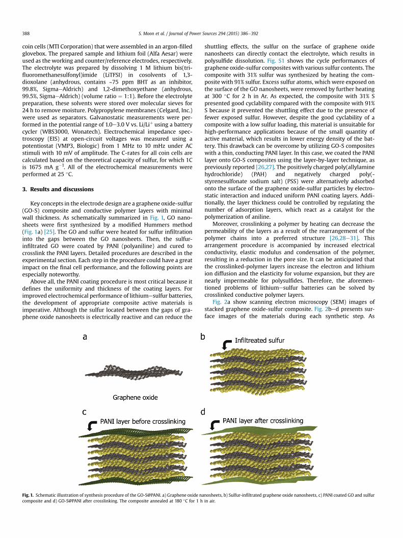
Key concepts in the electrode design are a graphene oxide-sulfur(GO-S) composite and conductive polymer layers with minimalwall thickness. As schematically summarized in Fig. 1, GO nano-sheets were first synthesized by a modified Hummers method(Fig. 1a) [25]. The GO and sulfur were heated for sulfur infiltrationinto the gaps between the GO nanosheets. Then, the sulfur-infiltrated GO were coated by PANI (polyaniline) and cured tocrosslink the PANI layers. Detailed procedures are described in theexperimental section. Each step in the procedure could have a greatimpact on the final cell performance, and the following points areespecially noteworthy.
Above all, the PANI coating procedure is most critical because itdefines the uniformity and thickness of the coating layers. Forimproved electrochemical performance of lithiumesulfur batteries,the development of appropriate composite active materials isimperative. Although the sulfur located between the gaps of gra-phene oxide nanosheets is electrically reactive and can reduce the
Fig. 1. Schematic illustration of synthesis procedure of the GO-S@PANI. a) Graphene oxide nacomposite and d) GO-S@PANI after crosslinking. The composite annealed at 180 �C for 1 h
shuttling effects, the sulfur on the surface of graphene oxidenanosheets can directly contact the electrolyte, which results inpolysulfide dissolution. Fig. S1 shows the cycle performances ofgraphene oxide-sulfur composites with various sulfur contents. Thecomposite with 31% sulfur was synthesized by heating the com-posite with 91% sulfur. Excess sulfur atoms, which were exposed onthe surface of the GO nanosheets, were removed by further heatingat 300 �C for 2 h in Ar. As expected, the composite with 31% Spresented good cyclability compared with the composite with 91%S because it prevented the shuttling effect due to the presence offewer exposed sulfur. However, despite the good cyclability of acomposite with a low sulfur loading, this material is unsuitable forhigh-performance applications because of the small quantity ofactive material, which results in lower energy density of the bat-tery. This drawback can be overcome by utilizing GO-S compositeswith a thin, conducting PANI layer. In this case, we coated the PANIlayer onto GO-S composites using the layer-by-layer technique, aspreviously reported [26,27]. The positively charged poly(allylaminehydrochloride) (PAH) and negatively charged poly(-styrenesulfonate sodium salt) (PSS) were alternatively adsorbedonto the surface of the graphene oxide-sulfur particles by electro-static interaction and induced uniform PANI coating layers. Addi-tionally, the layer thickness could be controlled by regulating thenumber of adsorption layers, which react as a catalyst for thepolymerization of aniline.
Moreover, crosslinking a polymer by heating can decrease thepermeability of the layers as a result of the rearrangement of thepolymer chains into a preferred structure [26,28e31]. Thisarrangement procedure is accompanied by increased electricalconductivity, elastic modulus and condensation of the polymer,resulting in a reduction in the pore size. It can be anticipated thatthe crosslinked-polymer layers increase the electron and lithiumion diffusion and the elasticity for volume expansion, but they arenearly impermeable for polysulfides. Therefore, the aforemen-tioned problems of lithiumesulfur batteries can be solved bycrosslinked conductive polymer layers.
Fig. 2a show scanning electron microscopy (SEM) images ofstacked graphene oxide-sulfur composite. Fig. 2bed presents sur-face images of the materials during each synthetic step. As
nosheets, b) Sulfur-infiltrated graphene oxide nanosheets, c) PANI coated GO and sulfurin air.
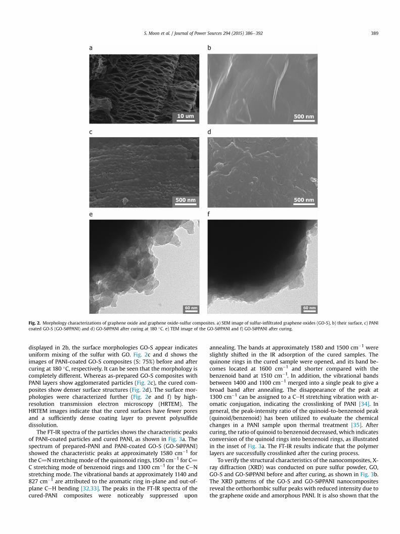
Fig. 2. Morphology characterizations of graphene oxide and graphene oxide-sulfur composites. a) SEM image of sulfur-infiltrated graphene oxides (GO-S), b) their surface, c) PANIcoated GO-S (GO-S@PANI) and d) GO-S@PANI after curing at 180 �C. e) TEM image of the GO-S@PANI and f) GO-S@PANI after curing.
S. Moon et al. / Journal of Power Sources 294 (2015) 386e392 389
displayed in 2b, the surface morphologies GO-S appear indicatesuniform mixing of the sulfur with GO. Fig. 2c and d shows theimages of PANI-coated GO-S composites (S: 75%) before and aftercuring at 180 �C, respectively. It can be seen that the morphology iscompletely different. Whereas as-prepared GO-S composites withPANI layers show agglomerated particles (Fig. 2c), the cured com-posites show denser surface structures (Fig. 2d). The surface mor-phologies were characterized further (Fig. 2e and f) by high-resolution transmission electron microscopy (HRTEM). TheHRTEM images indicate that the cured surfaces have fewer poresand a sufficiently dense coating layer to prevent polysulfidedissolution.
The FT-IR spectra of the particles shows the characteristic peaksof PANI-coated particles and cured PANI, as shown in Fig. 3a. Thespectrum of prepared-PANI and PANI-coated GO-S (GO-S@PANI)showed the characteristic peaks at approximately 1580 cm�1 forthe C]N stretchingmode of the quinonoid rings, 1500 cm�1 for C]C stretching mode of benzenoid rings and 1300 cm�1 for the CeNstretching mode. The vibrational bands at approximately 1140 and827 cm�1 are attributed to the aromatic ring in-plane and out-of-plane CeH bending [32,33]. The peaks in the FT-IR spectra of thecured-PANI composites were noticeably suppressed upon
annealing. The bands at approximately 1580 and 1500 cm�1 wereslightly shifted in the IR adsorption of the cured samples. Thequinone rings in the cured sample were opened, and its band be-comes located at 1600 cm�1 and shorter compared with thebenzenoid band at 1510 cm�1. In addition, the vibrational bandsbetween 1400 and 1100 cm�1 merged into a single peak to give abroad band after annealing. The disappearance of the peak at1300 cm�1 can be assigned to a CeH stretching vibration with ar-omatic conjugation, indicating the crosslinking of PANI [34]. Ingeneral, the peak-intensity ratio of the quinoid-to-benzenoid peak(quinoid/benzenoid) has been utilized to evaluate the chemicalchanges in a PANI sample upon thermal treatment [35]. Aftercuring, the ratio of quinoid to benzenoid decreased, which indicatesconversion of the quinoid rings into benzenoid rings, as illustratedin the inset of Fig. 3a. The FT-IR results indicate that the polymerlayers are successfully crosslinked after the curing process.
To verify the structural characteristics of the nanocomposites, X-ray diffraction (XRD) was conducted on pure sulfur powder, GO,GO-S and GO-S@PANI before and after curing, as shown in Fig. 3b.The XRD patterns of the GO-S and GO-S@PANI nanocompositesreveal the orthorhombic sulfur peaks with reduced intensity due tothe graphene oxide and amorphous PANI. It is also shown that the
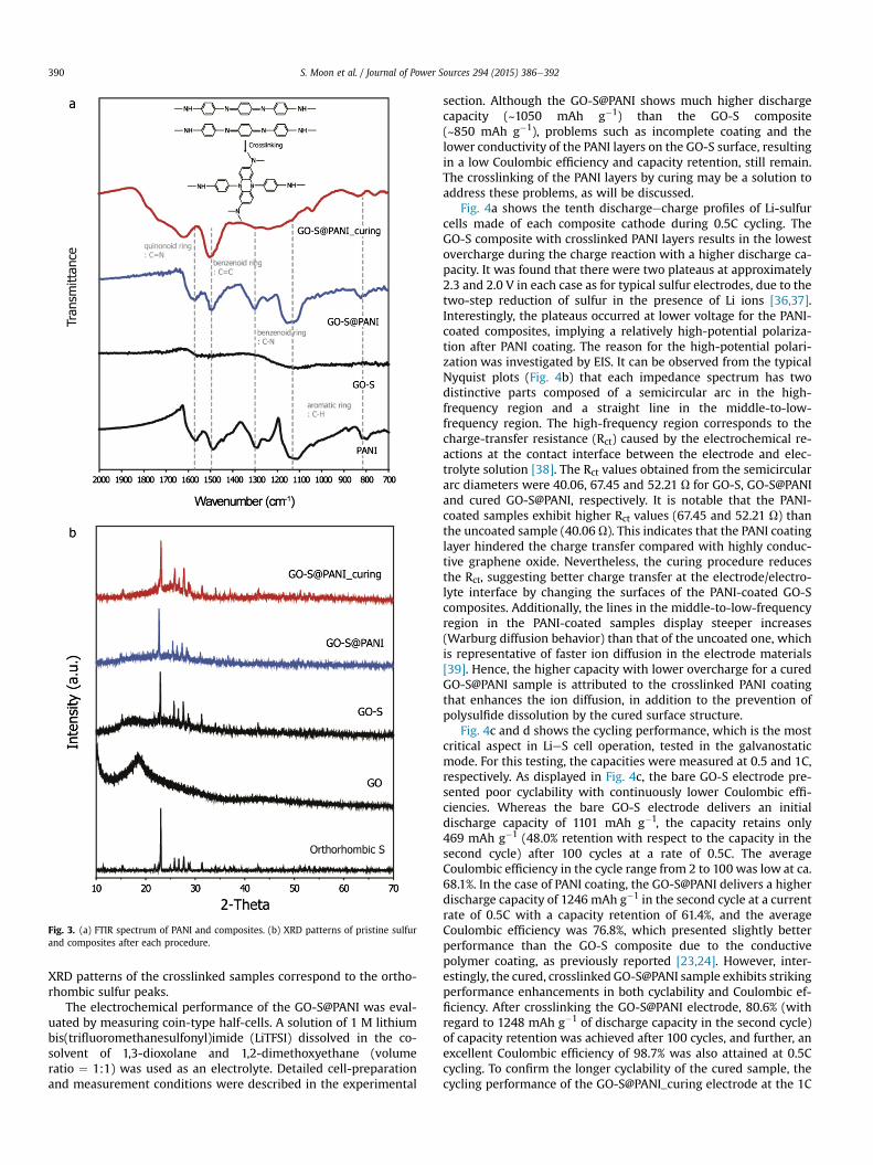
Fig. 3. (a) FTIR spectrum of PANI and composites. (b) XRD patterns of pristine sulfurand composites after each procedure.
S. Moon et al. / Journal of Power Sources 294 (2015) 386e392390
XRD patterns of the crosslinked samples correspond to the ortho-rhombic sulfur peaks.
The electrochemical performance of the GO-S@PANI was eval-uated by measuring coin-type half-cells. A solution of 1 M lithiumbis(trifluoromethanesulfonyl)imide (LiTFSI) dissolved in the co-solvent of 1,3-dioxolane and 1,2-dimethoxyethane (volumeratio ¼ 1:1) was used as an electrolyte. Detailed cell-preparationand measurement conditions were described in the experimental
section. Although the GO-S@PANI shows much higher dischargecapacity (~1050 mAh g�1) than the GO-S composite(~850 mAh g�1), problems such as incomplete coating and thelower conductivity of the PANI layers on the GO-S surface, resultingin a low Coulombic efficiency and capacity retention, still remain.The crosslinking of the PANI layers by curing may be a solution toaddress these problems, as will be discussed.
Fig. 4a shows the tenth dischargeecharge profiles of Li-sulfurcells made of each composite cathode during 0.5C cycling. TheGO-S composite with crosslinked PANI layers results in the lowestovercharge during the charge reaction with a higher discharge ca-pacity. It was found that there were two plateaus at approximately2.3 and 2.0 V in each case as for typical sulfur electrodes, due to thetwo-step reduction of sulfur in the presence of Li ions [36,37].Interestingly, the plateaus occurred at lower voltage for the PANI-coated composites, implying a relatively high-potential polariza-tion after PANI coating. The reason for the high-potential polari-zation was investigated by EIS. It can be observed from the typicalNyquist plots (Fig. 4b) that each impedance spectrum has twodistinctive parts composed of a semicircular arc in the high-frequency region and a straight line in the middle-to-low-frequency region. The high-frequency region corresponds to thecharge-transfer resistance (Rct) caused by the electrochemical re-actions at the contact interface between the electrode and elec-trolyte solution [38]. The Rct values obtained from the semicirculararc diameters were 40.06, 67.45 and 52.21 U for GO-S, GO-S@PANIand cured GO-S@PANI, respectively. It is notable that the PANI-coated samples exhibit higher Rct values (67.45 and 52.21 U) thanthe uncoated sample (40.06 U). This indicates that the PANI coatinglayer hindered the charge transfer compared with highly conduc-tive graphene oxide. Nevertheless, the curing procedure reducesthe Rct, suggesting better charge transfer at the electrode/electro-lyte interface by changing the surfaces of the PANI-coated GO-Scomposites. Additionally, the lines in the middle-to-low-frequencyregion in the PANI-coated samples display steeper increases(Warburg diffusion behavior) than that of the uncoated one, whichis representative of faster ion diffusion in the electrode materials[39]. Hence, the higher capacity with lower overcharge for a curedGO-S@PANI sample is attributed to the crosslinked PANI coatingthat enhances the ion diffusion, in addition to the prevention ofpolysulfide dissolution by the cured surface structure.
Fig. 4c and d shows the cycling performance, which is the mostcritical aspect in LieS cell operation, tested in the galvanostaticmode. For this testing, the capacities were measured at 0.5 and 1C,respectively. As displayed in Fig. 4c, the bare GO-S electrode pre-sented poor cyclability with continuously lower Coulombic effi-ciencies. Whereas the bare GO-S electrode delivers an initialdischarge capacity of 1101 mAh g�1, the capacity retains only469 mAh g�1 (48.0% retention with respect to the capacity in thesecond cycle) after 100 cycles at a rate of 0.5C. The averageCoulombic efficiency in the cycle range from 2 to 100 was low at ca.68.1%. In the case of PANI coating, the GO-S@PANI delivers a higherdischarge capacity of 1246 mAh g�1 in the second cycle at a currentrate of 0.5C with a capacity retention of 61.4%, and the averageCoulombic efficiency was 76.8%, which presented slightly betterperformance than the GO-S composite due to the conductivepolymer coating, as previously reported [23,24]. However, inter-estingly, the cured, crosslinked GO-S@PANI sample exhibits strikingperformance enhancements in both cyclability and Coulombic ef-ficiency. After crosslinking the GO-S@PANI electrode, 80.6% (withregard to 1248 mAh g�1 of discharge capacity in the second cycle)of capacity retention was achieved after 100 cycles, and further, anexcellent Coulombic efficiency of 98.7% was also attained at 0.5Ccycling. To confirm the longer cyclability of the cured sample, thecycling performance of the GO-S@PANI_curing electrode at the 1C
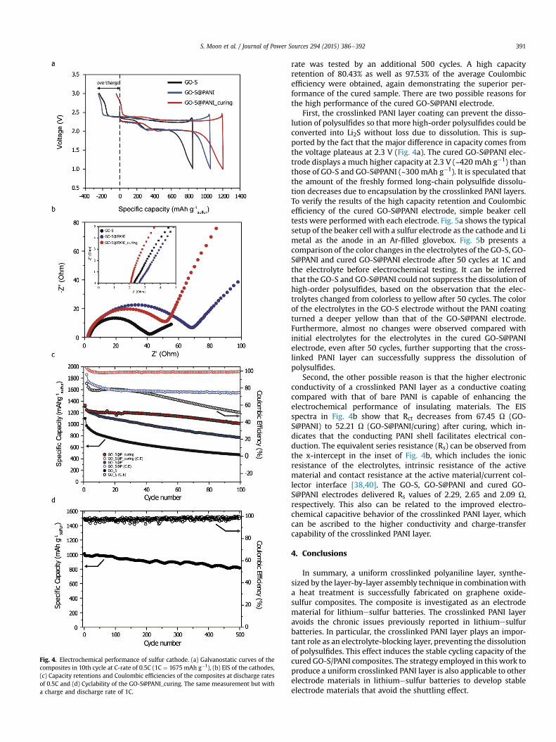
Fig. 4. Electrochemical performance of sulfur cathode. (a) Galvanostatic curves of thecomposites in 10th cycle at C-rate of 0.5C (1C ¼ 1675 mAh g�1), (b) EIS of the cathodes,(c) Capacity retentions and Coulombic efficiencies of the composites at discharge ratesof 0.5C and (d) Cyclability of the GO-S@PANI_curing. The same measurement but witha charge and discharge rate of 1C.
S. Moon et al. / Journal of Power Sources 294 (2015) 386e392 391
rate was tested by an additional 500 cycles. A high capacityretention of 80.43% as well as 97.53% of the average Coulombicefficiency were obtained, again demonstrating the superior per-formance of the cured sample. There are two possible reasons forthe high performance of the cured GO-S@PANI electrode.
First, the crosslinked PANI layer coating can prevent the disso-lution of polysulfides so that more high-order polysulfides could beconverted into Li2S without loss due to dissolution. This is sup-ported by the fact that the major difference in capacity comes fromthe voltage plateaus at 2.3 V (Fig. 4a). The cured GO-S@PANI elec-trode displays a much higher capacity at 2.3 V (~420 mAh g�1) thanthose of GO-S and GO-S@PANI (~300 mAh g�1). It is speculated thatthe amount of the freshly formed long-chain polysulfide dissolu-tion decreases due to encapsulation by the crosslinked PANI layers.To verify the results of the high capacity retention and Coulombicefficiency of the cured GO-S@PANI electrode, simple beaker celltests were performed with each electrode. Fig. 5a shows the typicalsetup of the beaker cell with a sulfur electrode as the cathode and Limetal as the anode in an Ar-filled glovebox. Fig. 5b presents acomparison of the color changes in the electrolytes of the GO-S, GO-S@PANI and cured GO-S@PANI electrode after 50 cycles at 1C andthe electrolyte before electrochemical testing. It can be inferredthat the GO-S and GO-S@PANI could not suppress the dissolution ofhigh-order polysulfides, based on the observation that the elec-trolytes changed from colorless to yellow after 50 cycles. The colorof the electrolytes in the GO-S electrode without the PANI coatingturned a deeper yellow than that of the GO-S@PANI electrode.Furthermore, almost no changes were observed compared withinitial electrolytes for the electrolytes in the cured GO-S@PANIelectrode, even after 50 cycles, further supporting that the cross-linked PANI layer can successfully suppress the dissolution ofpolysulfides.
Second, the other possible reason is that the higher electronicconductivity of a crosslinked PANI layer as a conductive coatingcompared with that of bare PANI is capable of enhancing theelectrochemical performance of insulating materials. The EISspectra in Fig. 4b show that Rct decreases from 67.45 U (GO-S@PANI) to 52.21 U (GO-S@PANI/curing) after curing, which in-dicates that the conducting PANI shell facilitates electrical con-duction. The equivalent series resistance (Rs) can be observed fromthe x-intercept in the inset of Fig. 4b, which includes the ionicresistance of the electrolytes, intrinsic resistance of the activematerial and contact resistance at the active material/current col-lector interface [38,40]. The GO-S, GO-S@PANI and cured GO-S@PANI electrodes delivered Rs values of 2.29, 2.65 and 2.09 U,respectively. This also can be related to the improved electro-chemical capacitive behavior of the crosslinked PANI layer, whichcan be ascribed to the higher conductivity and charge-transfercapability of the crosslinked PANI layer.
4. Conclusions
In summary, a uniform crosslinked polyaniline layer, synthe-sized by the layer-by-layer assembly technique in combinationwitha heat treatment is successfully fabricated on graphene oxide-sulfur composites. The composite is investigated as an electrodematerial for lithiumesulfur batteries. The crosslinked PANI layeravoids the chronic issues previously reported in lithiumesulfurbatteries. In particular, the crosslinked PANI layer plays an impor-tant role as an electrolyte-blocking layer, preventing the dissolutionof polysulfides. This effect induces the stable cycling capacity of thecured GO-S/PANI composites. The strategy employed in this work toproduce a uniform crosslinked PANI layer is also applicable to otherelectrode materials in lithiumesulfur batteries to develop stableelectrode materials that avoid the shuttling effect.
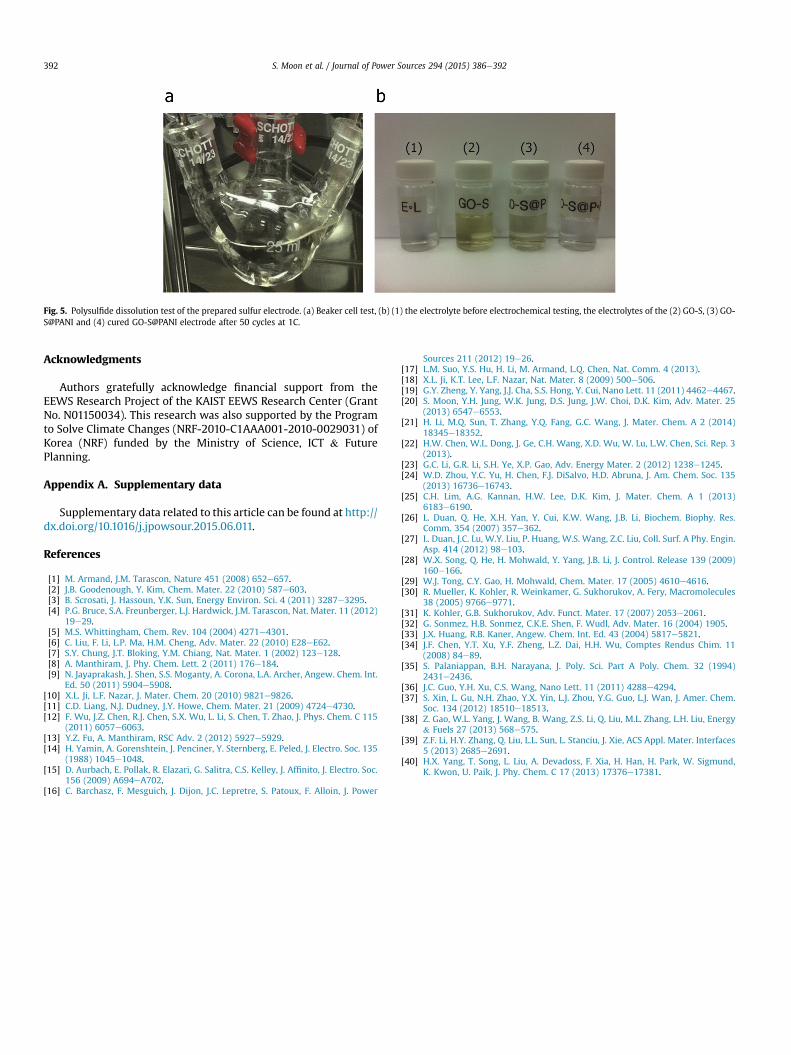
Fig. 5. Polysulfide dissolution test of the prepared sulfur electrode. (a) Beaker cell test, (b) (1) the electrolyte before electrochemical testing, the electrolytes of the (2) GO-S, (3) GO-S@PANI and (4) cured GO-S@PANI electrode after 50 cycles at 1C.
S. Moon et al. / Journal of Power Sources 294 (2015) 386e392392
Acknowledgments
Authors gratefully acknowledge financial support from theEEWS Research Project of the KAIST EEWS Research Center (GrantNo. N01150034). This research was also supported by the Programto Solve Climate Changes (NRF-2010-C1AAA001-2010-0029031) ofKorea (NRF) funded by the Ministry of Science, ICT & FuturePlanning.
Appendix A. Supplementary data
Supplementary data related to this article can be found at http://dx.doi.org/10.1016/j.jpowsour.2015.06.011.
References
[1] M. Armand, J.M. Tarascon, Nature 451 (2008) 652e657.[2] J.B. Goodenough, Y. Kim, Chem. Mater. 22 (2010) 587e603.[3] B. Scrosati, J. Hassoun, Y.K. Sun, Energy Environ. Sci. 4 (2011) 3287e3295.[4] P.G. Bruce, S.A. Freunberger, L.J. Hardwick, J.M. Tarascon, Nat. Mater. 11 (2012)
19e29.[5] M.S. Whittingham, Chem. Rev. 104 (2004) 4271e4301.[6] C. Liu, F. Li, L.P. Ma, H.M. Cheng, Adv. Mater. 22 (2010) E28eE62.[7] S.Y. Chung, J.T. Bloking, Y.M. Chiang, Nat. Mater. 1 (2002) 123e128.[8] A. Manthiram, J. Phy. Chem. Lett. 2 (2011) 176e184.[9] N. Jayaprakash, J. Shen, S.S. Moganty, A. Corona, L.A. Archer, Angew. Chem. Int.
Ed. 50 (2011) 5904e5908.[10] X.L. Ji, L.F. Nazar, J. Mater. Chem. 20 (2010) 9821e9826.[11] C.D. Liang, N.J. Dudney, J.Y. Howe, Chem. Mater. 21 (2009) 4724e4730.[12] F. Wu, J.Z. Chen, R.J. Chen, S.X. Wu, L. Li, S. Chen, T. Zhao, J. Phys. Chem. C 115
(2011) 6057e6063.[13] Y.Z. Fu, A. Manthiram, RSC Adv. 2 (2012) 5927e5929.[14] H. Yamin, A. Gorenshtein, J. Penciner, Y. Sternberg, E. Peled, J. Electro. Soc. 135
(1988) 1045e1048.[15] D. Aurbach, E. Pollak, R. Elazari, G. Salitra, C.S. Kelley, J. Affinito, J. Electro. Soc.
156 (2009) A694eA702.[16] C. Barchasz, F. Mesguich, J. Dijon, J.C. Lepretre, S. Patoux, F. Alloin, J. Power
Sources 211 (2012) 19e26.[17] L.M. Suo, Y.S. Hu, H. Li, M. Armand, L.Q. Chen, Nat. Comm. 4 (2013).[18] X.L. Ji, K.T. Lee, L.F. Nazar, Nat. Mater. 8 (2009) 500e506.[19] G.Y. Zheng, Y. Yang, J.J. Cha, S.S. Hong, Y. Cui, Nano Lett. 11 (2011) 4462e4467.[20] S. Moon, Y.H. Jung, W.K. Jung, D.S. Jung, J.W. Choi, D.K. Kim, Adv. Mater. 25
(2013) 6547e6553.[21] H. Li, M.Q. Sun, T. Zhang, Y.Q. Fang, G.C. Wang, J. Mater. Chem. A 2 (2014)
18345e18352.[22] H.W. Chen, W.L. Dong, J. Ge, C.H. Wang, X.D. Wu, W. Lu, L.W. Chen, Sci. Rep. 3
(2013).[23] G.C. Li, G.R. Li, S.H. Ye, X.P. Gao, Adv. Energy Mater. 2 (2012) 1238e1245.[24] W.D. Zhou, Y.C. Yu, H. Chen, F.J. DiSalvo, H.D. Abruna, J. Am. Chem. Soc. 135
(2013) 16736e16743.[25] C.H. Lim, A.G. Kannan, H.W. Lee, D.K. Kim, J. Mater. Chem. A 1 (2013)
6183e6190.[26] L. Duan, Q. He, X.H. Yan, Y. Cui, K.W. Wang, J.B. Li, Biochem. Biophy. Res.
Comm. 354 (2007) 357e362.[27] L. Duan, J.C. Lu, W.Y. Liu, P. Huang, W.S. Wang, Z.C. Liu, Coll. Surf. A Phy. Engin.
Asp. 414 (2012) 98e103.[28] W.X. Song, Q. He, H. Mohwald, Y. Yang, J.B. Li, J. Control. Release 139 (2009)
160e166.[29] W.J. Tong, C.Y. Gao, H. Mohwald, Chem. Mater. 17 (2005) 4610e4616.[30] R. Mueller, K. Kohler, R. Weinkamer, G. Sukhorukov, A. Fery, Macromolecules
38 (2005) 9766e9771.[31] K. Kohler, G.B. Sukhorukov, Adv. Funct. Mater. 17 (2007) 2053e2061.[32] G. Sonmez, H.B. Sonmez, C.K.E. Shen, F. Wudl, Adv. Mater. 16 (2004) 1905.[33] J.X. Huang, R.B. Kaner, Angew. Chem. Int. Ed. 43 (2004) 5817e5821.[34] J.F. Chen, Y.T. Xu, Y.F. Zheng, L.Z. Dai, H.H. Wu, Comptes Rendus Chim. 11
(2008) 84e89.[35] S. Palaniappan, B.H. Narayana, J. Poly. Sci. Part A Poly. Chem. 32 (1994)
2431e2436.[36] J.C. Guo, Y.H. Xu, C.S. Wang, Nano Lett. 11 (2011) 4288e4294.[37] S. Xin, L. Gu, N.H. Zhao, Y.X. Yin, L.J. Zhou, Y.G. Guo, L.J. Wan, J. Amer. Chem.
Soc. 134 (2012) 18510e18513.[38] Z. Gao, W.L. Yang, J. Wang, B. Wang, Z.S. Li, Q. Liu, M.L. Zhang, L.H. Liu, Energy
& Fuels 27 (2013) 568e575.[39] Z.F. Li, H.Y. Zhang, Q. Liu, L.L. Sun, L. Stanciu, J. Xie, ACS Appl. Mater. Interfaces
5 (2013) 2685e2691.[40] H.X. Yang, T. Song, L. Liu, A. Devadoss, F. Xia, H. Han, H. Park, W. Sigmund,
K. Kwon, U. Paik, J. Phy. Chem. C 17 (2013) 17376e17381.