Embed Size (px)
Citation preview
lable at ScienceDirect
Journal of Power Sources 273 (2015) 823e830
Contents lists avai
Journal of Power Sources
journal homepage: www.elsevier .com/locate/ jpowsour
A high power density miniaturized microbial fuel cell having carbonnanotube anodes
Hao Ren a, *, Soonjae Pyo b, Jae-Ik Lee b, Tae-Jin Park c, Forrest S. Gittleson d,Frederick C.C. Leung c, Jongbaeg Kim b, Andr�e D. Taylor d, Hyung-Sool Lee e,Junseok Chae a
a School of Electrical, Computer, and Energy Engineering, Arizona State University, USAb Department of Mechanical Engineering, Yonsei University, Republic of Koreac School of Biological Sciences, The University of Hong Kong, Chinad Department of Chemical & Environmental Engineering, Yale University, USAe Department of Civil and Environmental Engineering, University of Waterloo, Canada
h i g h l i g h t s
* Corresponding author. 650 E. Tyler Mall, GWC 30E-mail addresses: [email protected], haoren.ustc@g
http://dx.doi.org/10.1016/j.jpowsour.2014.09.1650378-7753/© 2014 Elsevier B.V. All rights reserved.
g r a p h i c a l a b s t r a c t
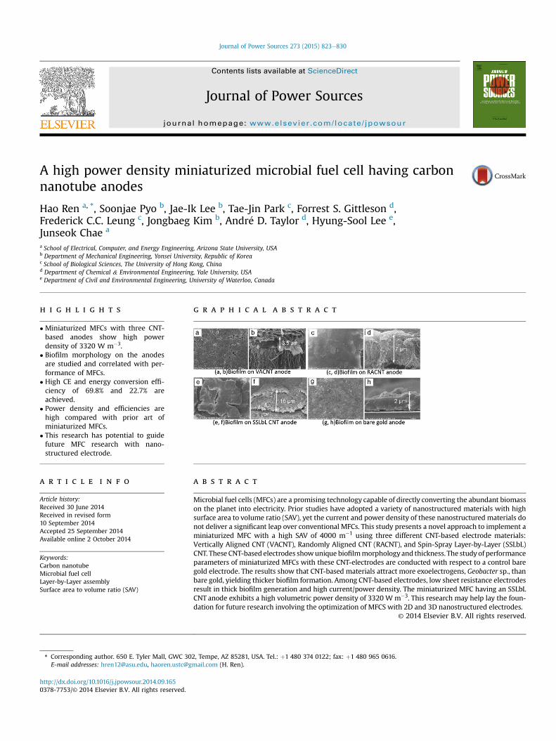
� Miniaturized MFCs with three CNT-based anodes show high powerdensity of 3320 W m�3.
� Biofilm morphology on the anodesare studied and correlated with per-formance of MFCs.
� High CE and energy conversion effi-ciency of 69.8% and 22.7% areachieved.
� Power density and efficiencies arehigh compared with prior art ofminiaturized MFCs.
� This research has potential to guidefuture MFC research with nano-structured electrode.
a r t i c l e i n f o
Article history:Received 30 June 2014Received in revised form10 September 2014Accepted 25 September 2014Available online 2 October 2014
Keywords:Carbon nanotubeMicrobial fuel cellLayer-by-Layer assemblySurface area to volume ratio (SAV)
a b s t r a c t
Microbial fuel cells (MFCs) are a promising technology capable of directly converting the abundant biomasson the planet into electricity. Prior studies have adopted a variety of nanostructured materials with highsurface area to volume ratio (SAV), yet the current and power density of these nanostructured materials donot deliver a significant leap over conventional MFCs. This study presents a novel approach to implement aminiaturized MFC with a high SAV of 4000 m�1 using three different CNT-based electrode materials:Vertically Aligned CNT (VACNT), Randomly Aligned CNT (RACNT), and Spin-Spray Layer-by-Layer (SSLbL)CNT. These CNT-based electrodes showunique biofilmmorphologyand thickness. The studyof performanceparameters of miniaturized MFCs with these CNT-electrodes are conducted with respect to a control baregold electrode. The results show that CNT-based materials attract more exoelectrogens, Geobacter sp., thanbare gold, yielding thicker biofilm formation. Among CNT-based electrodes, low sheet resistance electrodesresult in thick biofilm generation and high current/power density. The miniaturized MFC having an SSLbLCNT anode exhibits a high volumetric power density of 3320 W m�3. This research may help lay the foun-dation for future research involving the optimization of MFCS with 2D and 3D nanostructured electrodes.
© 2014 Elsevier B.V. All rights reserved.
2, Tempe, AZ 85281, USA. Tel.: þ1 480 374 0122; fax: þ1 480 965 0616.mail.com (H. Ren).
H. Ren et al. / Journal of Power Sources 273 (2015) 823e830824
1. Introduction
Amidst global warming and the negative implications of energyfrom fossil fuels, there has been significant interest in the devel-opment of sustainable energy sources [1]. Bioenergy couldpotentially constitute a large part of the renewable energy port-folio, provided that the Earth's abundant biomass can beeconomically converted [2]. Unlike conventional biomass energyconversion techniques, a microbial fuel cell (MFC) is an electro-chemical fuel cell that directly converts chemical energy of organiccompounds to electrical energy through catalytic reactions ofspecific microbes called exoelectrogens or anode-respiring bacte-ria [3e5]. This direct conversion process allows electricity to begenerated without intermediate products or equipment, andbenefits MFCs' high energy conversion efficiency. During the pastfew decades, various types of MFCs have been reported in appli-cations for wastewater treatment and renewable energy produc-tion [6e10], bioremediation of toxic components [11,12], andpower supplies for remote sensors in hazardous or environmen-tally unfriendly conditions [13].
Researchers have adopted different materials-such as carboncloth, carbon mesh, graphite rod, felt, foam, fiber brush, reticulatedvitreous carbon, tungsten carbide powder, etc., which have a highsurface area to volume ratio (SAV) as well as mechanical andelectrochemical stability [14e19]. Recent research has beenfocusing on implementing 2D and 3D nanostructured materialswith high SAV such as carbon nanotubes (CNT) and graphene. CNTand graphene are two nanostructured carbon allotropes, whichare attractive materials due to their high SAV, high conductivity,excellent electrochemical characteristics, superb mechanical andchemical stability, and manufacturing compatibility with batch-mode microfabrication [20e23]. Both CNTs and graphene havebeen used as 2D and 3D carbon based anode materials for MFCs,such as in graphene sponge [24], reduced graphene oxide oncarbon fiber [25], CNT/polyaniline or CNT/chitosan composite[26,27], multi-walled CNT [28e30], polyaniline hybridized gra-phene [31], chitosan/vacuum-stripped graphene scaffold [32], 3Dgraphene on Ni foam [33,34], and reduced graphene oxide/CNTcoated scaffold [35], yielding a SAV as high as 20,000 m�1; how-ever, the reported maximum areal power density ranges from19 mW m�2 to 1.57 W m�2. Based on projected electrode area, thevolumetric power density ranges from 6.3 W m�3 to 392 W m�3
[24,29,36], which still does not deliver a significant leap overconventional MFCs. Moreover, the biocompatibility of CNTs re-mains questionable [37] and some prior studies of CNT-basedMFCs show lower performance than MFCs having anodes of con-ventional carbon-based materials [26,28,38,39]. Besides imple-menting high SAV materials as anode, the cathode impacts theperformance of MFCs significantly as well - especially air-cathodeMFCs [40]. CNTs and graphene based materials have also beenused as cathodes materials in air-cathode MFCs, of which thecathode becomes the bottleneck, as reported by Wang et al. 2011and Khilari et al. 2013 [41,42].
Miniaturized MFCs reduce the characteristic length scales ofMFCs to the micrometer range, which results in chamber volumeswhich are on the mL scale [36,43e47]. In this work, we report theformation and morphology of biofilm on three different CNT-basedelectrode materials, and correlate the biofilm formation andmorphology to the characteristics of the miniaturized MFC,including coulombic efficiency and areal/volumetric power density.The three types of anodes using CNT materials with different sheetresistance and morphology are: (1) Vertically Aligned CarbonNanotubes (VACNT), (2) Randomly Aligned Carbon Nanotubes(RACNT), and (3) Spin-Spray Layer-by-Layer Carbon Nanotubes(SSLbL CNT).
2. Experimental
2.1. Bare gold electrode
The bare gold electrodes were deposited on a glass slide (microslides, 4.6 � 2.6 � 0.1 cm3, VWR) with six through holes pre-drilledmechanically (12 inch Bench Drill, Model 315.219140, Craftsman):one inlet, one outlet, and four for assembly (Fig. S1(a)). Afterward,Cr/Au (20 nm/200 nm) films were deposited on the glass slides viasputtering on the glass slides (Emitech K675XD Turbo SputterCoater) (Fig. S1(b)). We chose a bare gold anode as control,following prior work that reported little difference exists on theattraction of Geobacter on carbon based material and gold [48].
2.2. VACNT and RACNT
The VACNTs were directly synthesized on a quartz slide (quartzmicroscope slide, 5.08 � 2.54 � 0.1 cm3, Alfa Aesar) by catalyticchemical vapor deposition (CVD) (Fig. S1(e)) [49]. After 5 nm-thickiron (Fe) catalysts were deposited on the quartz slide by electron-beam evaporation, the quartz slide was placed into a growthchamber. The temperature and pressure for CNT synthesis was700 �C and 4 Torr, respectively. When the growth conditions werestabilized, the chamber was purged with nitrogen (N2) gas of 10sccm. The CNTs were then grown under acetylene (C2H2) ambienceafter ammonia (NH3) pretreatment for 30 min. The NH3 pretreat-ment is necessary for the vertical alignment of CNTs [50]. Incontrast to the synthesis of VACNTs, RACNTs were synthesizedwithout NH3 pretreatment. VACNT shows highly directional CNTgrowth due to strong van der Waals interaction between denselygrown CNTs. NH3 prevents Fe catalysts from being covered byamorphous carbon during synthesis, resulting in a high density ofnucleation sites for CNTs growth. Without NH3 pretreatment,curved and randomly oriented CNTs are synthesized and amor-phous carbon is found between the CNTs.
2.3. SSLbL CNT
The SSLbL apparatus and experimental procedure for assem-bling polymer-CNT nano-composite films has been described pre-viously [51]. Briefly, the SSLbL apparatus allows the sequentialspraying of polyelectrolyte solutions and the rinsing of water onto ahorizontal rotating substrate using three vertically-orientedsprayers and a spin-coater. For SSLbL anode films, an aqueous so-lution of 1% poly(styrene sulfonate) with 0.5 mgmL�1 multi-walledcarbon nanotubes was prepared with three hours of bath sonicat-ion followed by 45 min of tip sonication and 1.5 h of centrifugationat 3000 rpm to produce a stable dispersion. A solution of 10-mMpoly(vinyl alcohol) at a pH of 2.8 was used as the polycation. Baregold-coated glass slides were mounted onto the SSLbL vacuumchuck and rotated at 3000 rpm while solutions and rinse waterwere sprayed. A single bilayer was assembled using a spray/dryprocedure of polycation, rinse, dry, polyanion, rinse, and dry.Deionized water matching the pH of the polycation solution wasused for the rinse. Between bilayers, the substrate was dried atapproximately 45 �C for 4 s. The multi-walled carbon nanotubesused in SSLbL CNTelectrodes have amedian diameter of 6.6 nm andan aspect ratio ~1000.
2.4. Inoculum
The inoculum for the micro-scale MFC was obtained from anacetate-fed microbial electrolysis cell (MEC), which had a Geo-bacter-enriched bacterial community originally from anaerobic-digestion sludge. The anolyte was composed of a 25-mM sodium
H. Ren et al. / Journal of Power Sources 273 (2015) 823e830 825
acetate medium with 1680 mg KH2PO4, 12,400 mg Na2HPO4,1600 mg NaCl, 380 mg NH4Cl, 5 mg EDTA, 30 mg MgSO4$7H2O,5 mgMnSO4$H2O,10mg NaCl, 1 mg Co(NO3)2, 1 mg CaCl2, 0.001mgZnSO4$7H2O, 0.001 mg ZnSO4$7H2O, 0.1 mg CuSO4$5H2O, 0.1 mgAlK(SO4)2, 0.1 mg H3BO3, 0.1 mg Na2MoO4$2H2O, 0.1 mg Na2SeO3,0.1 mg Na2WO4$2H2O, 0.2 mg NiCl2$6H2O, and 1 mg FeSO4$7H2O(per liter of deionized water) (pH 7.8 ± 0.2). For the start-up pro-cess, inoculum and anolyte were mixed at a volumetric ratio of 1:1.The catholyte was composed of 100-mM potassium ferricyanide ina 100-mM phosphate buffer solution (pH 7.4). The anolyte andcatholyte were supplied into the micro-scale MFC using a syringepump. The MFCs operated at 30 �C.
2.5. Start-up and data acquisition
Anolyte/catholyte solutions were pumped into the corre-sponding chambers at a flow rate of 0.25 mL min�1. It typically takes5e7 days to form a mature biofilm (Fig. S3). Once the start-upprocess completes, the output current begins to reach steady state.
The current generated by the MFCs was recorded every minuteby measuring voltage drop across an external resistor connectedbetween the anode and the cathode using a data acquisition system(DAQ/68, National Instrument). During start-up, the MFCs wereoperated at 0.25 mL min�1 and the external resistor was set to 148-U. Once the start-up process completed, the flow ratewas increasedand polarization measurement was performed. For the polarizationcurve measurement, a series of resistors was employed, rangingfrom 148 U to 932 kU.
2.6. Coulombic efficiency (CE) and energy conversion efficiencymeasurement
Coulombic efficiency and energy conversion efficiency weremeasured by stopping the anolyte supply while keeping the cath-olyte supply; the current over timedomainwasmonitoredwhile thecatholyte kept flowing. Coulombic efficiency is the ratio of totalcoulombs transferred to the anode from the substrate to themaximum possible coulombs transferred if all substrate removalproduced current. That is, CE ¼ CP/CT � 100%, where CP is the totalcoulombs calculated by integrating the current over the time forsubstrate consumption andCT is themaximumpossible coulombs ofthe substrate CT ¼ V � b � A � e � (molsubstrate). V is the volume ofanode chamber (m3), b is the numberofmoles of electrons producedby oxidation of substrate (b¼ 8mol e�/mol acetate), A is Avogadro'snumber (6.023 � 1023 molecules/mol), e is the electron charge(1.6 � 10�19C/electron), and molsubstrate is the moles of acetateoxidized. The CE measurement of VACNT, RACNT and bare goldanode is illustrated in Fig. S4 (CE of SSLbL CNT is shown in Fig. 4).
Energy conversion efficiency is the ratio of total energy har-vested by the MFC to the maximum possible energy that thebiomass can produce (standard molar enthalpy of biomass): h ¼ EP/ET� 100%, where EP is the total energy calculated by integrating thepower output over the time for substrate consumption and ET is themaximum possible energy of the biomass ET¼ V� c� DfH�. V is thevolume of the anode chamber (m3), c is the concentration ofbiomass in the anode chamber (c ¼ 25 mol m�3, sodium acetate),and DfH� is the standard molar enthalpy of formation(708.8 kJ mol�1 for sodium acetate).
3. Results and discussion
3.1. Biofilm morphology and thickness on three CNT-based anodes
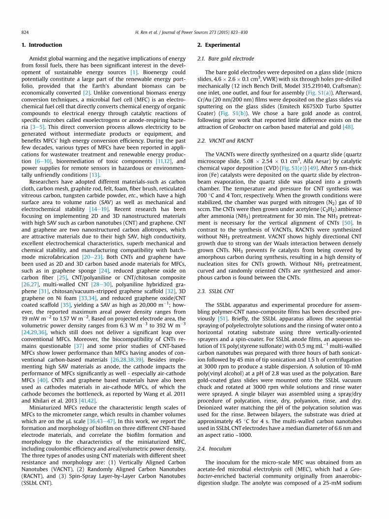
Fig. 1 shows the SEM images of the three CNT-based materials.Sheet resistance of the anodes was measured by a four-point probe
method. The sheet resistance of VACNT, RACNT, SSLbL CNT, and baregold electrodes were measured to be 1.48 ± 0.004 � 103,2.98 ± 0.354 � 103, 3.84 ± 0.17 � 100, and3.68 ± 0.07 � 100 U square�1 respectively. VACNT and RACNTelectrodes have substantially higher sheet resistance than those ofSSLbL CNT and bare gold electrodes.
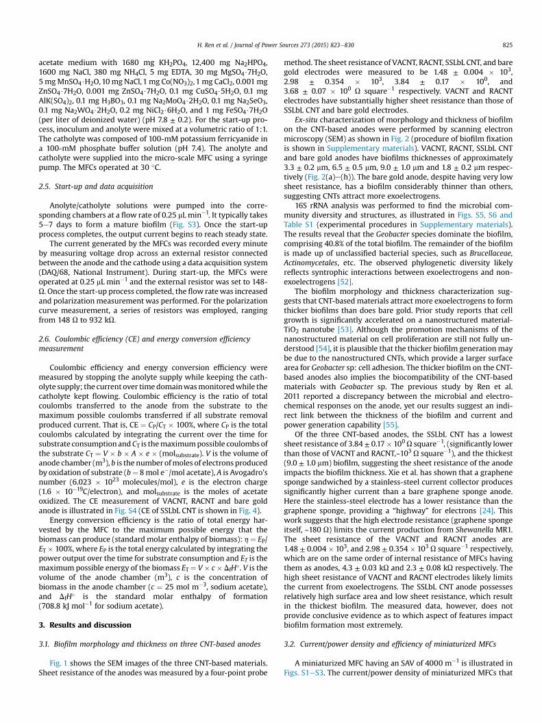
Ex-situ characterization of morphology and thickness of biofilmon the CNT-based anodes were performed by scanning electronmicroscopy (SEM) as shown in Fig. 2 (procedure of biofilm fixationis shown in Supplementary materials). VACNT, RACNT, SSLbL CNTand bare gold anodes have biofilms thicknesses of approximately3.3 ± 0.2 mm, 6.5 ± 0.5 mm, 9.0 ± 1.0 mm and 1.8 ± 0.2 mm respec-tively (Fig. 2(a)e(h)). The bare gold anode, despite having very lowsheet resistance, has a biofilm considerably thinner than others,suggesting CNTs attract more exoelectrogens.
16S rRNA analysis was performed to find the microbial com-munity diversity and structures, as illustrated in Figs. S5, S6 andTable S1 (experimental procedures in Supplementary materials).The results reveal that the Geobacter species dominate the biofilm,comprising 40.8% of the total biofilm. The remainder of the biofilmis made up of unclassified bacterial species, such as Brucellaceae,Actinomycetales, etc. The observed phylogenetic diversity likelyreflects syntrophic interactions between exoelectrogens and non-exoelectrogens [52].
The biofilm morphology and thickness characterization sug-gests that CNT-based materials attract more exoelectrogens to formthicker biofilms than does bare gold. Prior study reports that cellgrowth is significantly accelerated on a nanostructured material-TiO2 nanotube [53]. Although the promotion mechanisms of thenanostructured material on cell proliferation are still not fully un-derstood [54], it is plausible that the thicker biofilm generationmaybe due to the nanostructured CNTs, which provide a larger surfacearea for Geobacter sp: cell adhesion. The thicker biofilm on the CNT-based anodes also implies the biocompatibility of the CNT-basedmaterials with Geobacter sp. The previous study by Ren et al.2011 reported a discrepancy between the microbial and electro-chemical responses on the anode, yet our results suggest an indi-rect link between the thickness of the biofilm and current andpower generation capability [55].
Of the three CNT-based anodes, the SSLbL CNT has a lowestsheet resistance of 3.84 ± 0.17� 100U square�1, (significantly lowerthan those of VACNT and RACNT,~103 U square�1), and the thickest(9.0 ± 1.0 mm) biofilm, suggesting the sheet resistance of the anodeimpacts the biofilm thickness. Xie et al. has shown that a graphenesponge sandwiched by a stainless-steel current collector producessignificantly higher current than a bare graphene sponge anode.Here the stainless-steel electrode has a lower resistance than thegraphene sponge, providing a “highway” for electrons [24]. Thiswork suggests that the high electrode resistance (graphene spongeitself, ~180 U) limits the current production from Shewanella MR1.The sheet resistance of the VACNT and RACNT anodes are1.48 ± 0.004 � 103, and 2.98 ± 0.354 � 103 U square�1 respectively,which are on the same order of internal resistance of MFCs havingthem as anodes, 4.3 ± 0.03 kU and 2.3 ± 0.08 kU respectively. Thehigh sheet resistance of VACNT and RACNT electrodes likely limitsthe current from exoelectrogens. The SSLbL CNT anode possessesrelatively high surface area and low sheet resistance, which resultin the thickest biofilm. The measured data, however, does notprovide conclusive evidence as to which aspect of features impactbiofilm formation most extremely.
3.2. Current/power density and efficiency of miniaturized MFCs
A miniaturized MFC having an SAV of 4000 m�1 is illustrated inFigs. S1eS3. The current/power density of miniaturized MFCs that
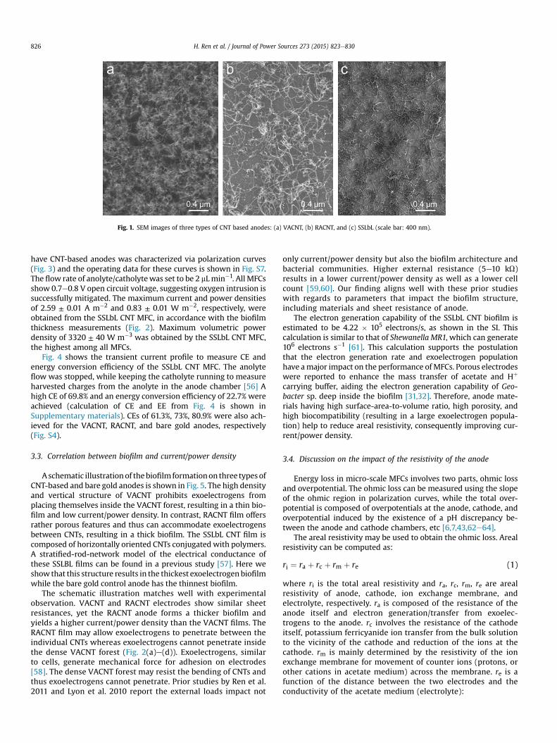
Fig. 1. SEM images of three types of CNT based anodes: (a) VACNT, (b) RACNT, and (c) SSLbL (scale bar: 400 nm).
H. Ren et al. / Journal of Power Sources 273 (2015) 823e830826
have CNT-based anodes was characterized via polarization curves(Fig. 3) and the operating data for these curves is shown in Fig. S7.The flow rate of anolyte/catholytewas set to be 2 mLmin�1. All MFCsshow 0.7e0.8 V open circuit voltage, suggesting oxygen intrusion issuccessfully mitigated. The maximum current and power densitiesof 2.59 ± 0.01 A m�2 and 0.83 ± 0.01 W m�2, respectively, wereobtained from the SSLbL CNT MFC, in accordance with the biofilmthickness measurements (Fig. 2). Maximum volumetric powerdensity of 3320 ± 40 W m�3 was obtained by the SSLbL CNT MFC,the highest among all MFCs.
Fig. 4 shows the transient current profile to measure CE andenergy conversion efficiency of the SSLbL CNT MFC. The anolyteflow was stopped, while keeping the catholyte running to measureharvested charges from the anolyte in the anode chamber [56] Ahigh CE of 69.8% and an energy conversion efficiency of 22.7% wereachieved (calculation of CE and EE from Fig. 4 is shown inSupplementary materials). CEs of 61.3%, 73%, 80.9% were also ach-ieved for the VACNT, RACNT, and bare gold anodes, respectively(Fig. S4).
3.3. Correlation between biofilm and current/power density
Aschematic illustrationof thebiofilm formationon three types ofCNT-based and bare gold anodes is shown in Fig. 5. The high densityand vertical structure of VACNT prohibits exoelectrogens fromplacing themselves inside the VACNT forest, resulting in a thin bio-film and low current/power density. In contrast, RACNT film offersrather porous features and thus can accommodate exoelectrogensbetween CNTs, resulting in a thick biofilm. The SSLbL CNT film iscomposed of horizontally oriented CNTs conjugated with polymers.A stratified-rod-network model of the electrical conductance ofthese SSLBL films can be found in a previous study [57]. Here weshow that this structure results in the thickest exoelectrogenbiofilmwhile the bare gold control anode has the thinnest biofilm.
The schematic illustration matches well with experimentalobservation. VACNT and RACNT electrodes show similar sheetresistances, yet the RACNT anode forms a thicker biofilm andyields a higher current/power density than the VACNT films. TheRACNT film may allow exoelectrogens to penetrate between theindividual CNTs whereas exoelectrogens cannot penetrate insidethe dense VACNT forest (Fig. 2(a)e(d)). Exoelectrogens, similarto cells, generate mechanical force for adhesion on electrodes[58]. The dense VACNT forest may resist the bending of CNTs andthus exoelectrogens cannot penetrate. Prior studies by Ren et al.2011 and Lyon et al. 2010 report the external loads impact not
only current/power density but also the biofilm architecture andbacterial communities. Higher external resistance (5e10 kU)results in a lower current/power density as well as a lower cellcount [59,60]. Our finding aligns well with these prior studieswith regards to parameters that impact the biofilm structure,including materials and sheet resistance of anode.
The electron generation capability of the SSLbL CNT biofilm isestimated to be 4.22 � 105 electrons/s, as shown in the SI. Thiscalculation is similar to that of Shewanella MR1, which can generate106 electrons s�1 [61]. This calculation supports the postulationthat the electron generation rate and exoelectrogen populationhave amajor impact on the performance ofMFCs. Porous electrodeswere reported to enhance the mass transfer of acetate and Hþ
carrying buffer, aiding the electron generation capability of Geo-bacter sp. deep inside the biofilm [31,32]. Therefore, anode mate-rials having high surface-area-to-volume ratio, high porosity, andhigh biocompatibility (resulting in a large exoelectrogen popula-tion) help to reduce areal resistivity, consequently improving cur-rent/power density.
3.4. Discussion on the impact of the resistivity of the anode
Energy loss in micro-scale MFCs involves two parts, ohmic lossand overpotential. The ohmic loss can be measured using the slopeof the ohmic region in polarization curves, while the total over-potential is composed of overpotentials at the anode, cathode, andoverpotential induced by the existence of a pH discrepancy be-tween the anode and cathode chambers, etc [6,7,43,62e64].
The areal resistivity may be used to obtain the ohmic loss. Arealresistivity can be computed as:
ri ¼ ra þ rc þ rm þ re (1)
where ri is the total areal resistivity and ra, rc, rm, re are arealresistivity of anode, cathode, ion exchange membrane, andelectrolyte, respectively. ra is composed of the resistance of theanode itself and electron generation/transfer from exoelec-trogens to the anode. rc involves the resistance of the cathodeitself, potassium ferricyanide ion transfer from the bulk solutionto the vicinity of the cathode and reduction of the ions at thecathode. rm is mainly determined by the resistivity of the ionexchange membrane for movement of counter ions (protons, orother cations in acetate medium) across the membrane. re is afunction of the distance between the two electrodes and theconductivity of the acetate medium (electrolyte):
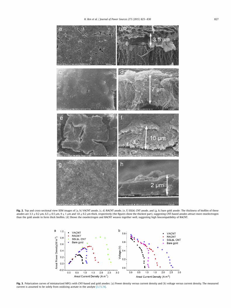
Fig. 2. Top and cross-sectional view SEM images of (a, b) VACNT anode, (c, d) RACNT anode, (e, f) SSLbL CNT anode, and (g, h) bare gold anode: The thickness of biofilm of theseanodes are 3.3 ± 0.2 mm, 6.5 ± 0.5 mm, 9 ± 1 mm and 1.8 ± 0.2 mm thick, respectively (the figures show the thickest part), suggesting CNT-based anodes attract more exoelectrogenthan the gold anode to form thick biofilm. (d) Shows the exoelectrogen and RACNT weaves together well, suggesting high biocompatibility of RACNT.
Fig. 3. Polarization curves of miniaturized MFCs with CNT-based and gold anodes: (a) Power density versus current density and (b) voltage versus current density. The measuredcurrent is assumed to be solely from oxidizing acetate in the anolyte [3,73,74].
H. Ren et al. / Journal of Power Sources 273 (2015) 823e830 827
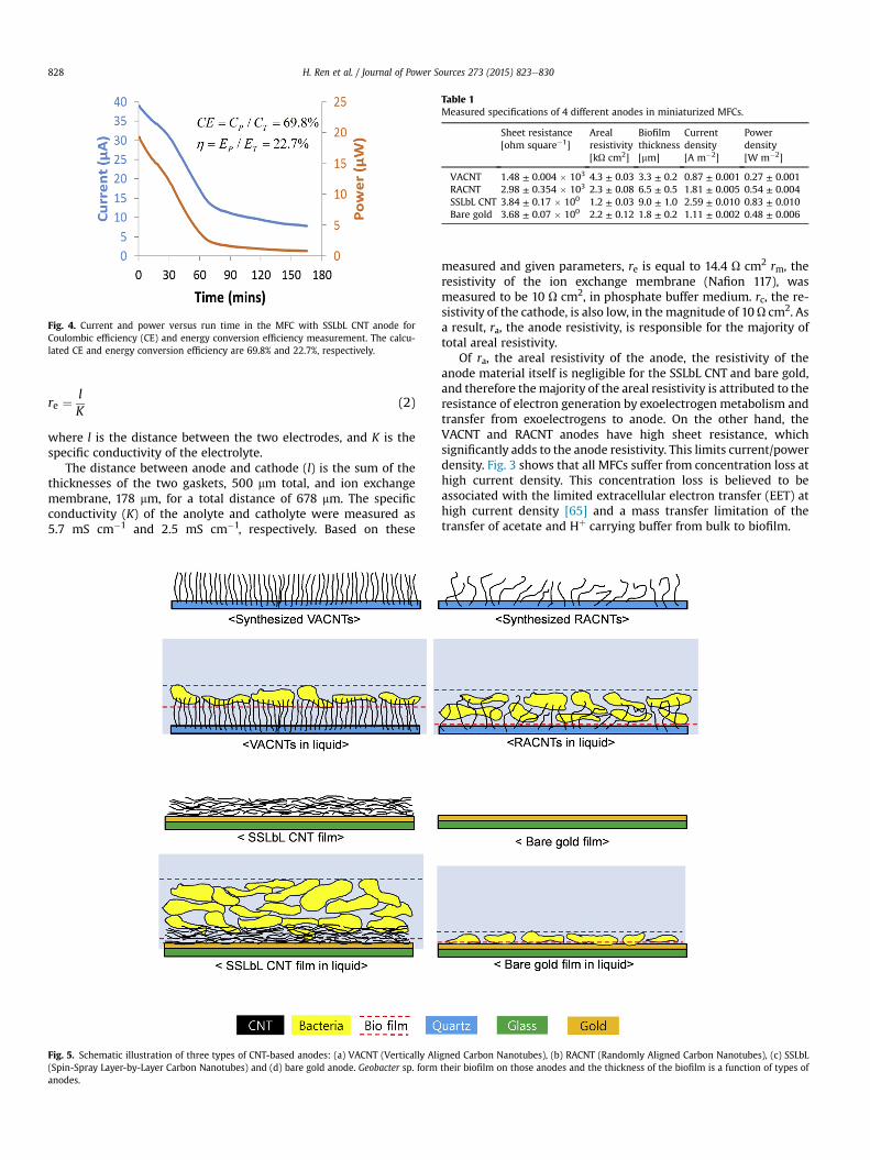
Fig. 4. Current and power versus run time in the MFC with SSLbL CNT anode forCoulombic efficiency (CE) and energy conversion efficiency measurement. The calcu-lated CE and energy conversion efficiency are 69.8% and 22.7%, respectively.
Table 1Measured specifications of 4 different anodes in miniaturized MFCs.
Sheet resistance[ohm square�1]
Arealresistivity[kU cm2]
Biofilmthickness[mm]
Currentdensity[A m�2]
Powerdensity[W m�2]
VACNT 1.48 ± 0.004 � 103 4.3 ± 0.03 3.3 ± 0.2 0.87 ± 0.001 0.27 ± 0.001RACNT 2.98 ± 0.354 � 103 2.3 ± 0.08 6.5 ± 0.5 1.81 ± 0.005 0.54 ± 0.004SSLbL CNT 3.84 ± 0.17 � 100 1.2 ± 0.03 9.0 ± 1.0 2.59 ± 0.010 0.83 ± 0.010Bare gold 3.68 ± 0.07 � 100 2.2 ± 0.12 1.8 ± 0.2 1.11 ± 0.002 0.48 ± 0.006
H. Ren et al. / Journal of Power Sources 273 (2015) 823e830828
re ¼ lK
(2)
where l is the distance between the two electrodes, and K is thespecific conductivity of the electrolyte.
The distance between anode and cathode (l) is the sum of thethicknesses of the two gaskets, 500 mm total, and ion exchangemembrane, 178 mm, for a total distance of 678 mm. The specificconductivity (K) of the anolyte and catholyte were measured as5.7 mS cm�1 and 2.5 mS cm�1, respectively. Based on these
Fig. 5. Schematic illustration of three types of CNT-based anodes: (a) VACNT (Vertically Ali(Spin-Spray Layer-by-Layer Carbon Nanotubes) and (d) bare gold anode. Geobacter sp. formanodes.
measured and given parameters, re is equal to 14.4 U cm2 rm, theresistivity of the ion exchange membrane (Nafion 117), wasmeasured to be 10 U cm2, in phosphate buffer medium. rc, the re-sistivity of the cathode, is also low, in the magnitude of 10 U cm2. Asa result, ra, the anode resistivity, is responsible for the majority oftotal areal resistivity.
Of ra, the areal resistivity of the anode, the resistivity of theanode material itself is negligible for the SSLbL CNT and bare gold,and therefore themajority of the areal resistivity is attributed to theresistance of electron generation by exoelectrogen metabolism andtransfer from exoelectrogens to anode. On the other hand, theVACNT and RACNT anodes have high sheet resistance, whichsignificantly adds to the anode resistivity. This limits current/powerdensity. Fig. 3 shows that all MFCs suffer from concentration loss athigh current density. This concentration loss is believed to beassociated with the limited extracellular electron transfer (EET) athigh current density [65] and a mass transfer limitation of thetransfer of acetate and Hþ carrying buffer from bulk to biofilm.
gned Carbon Nanotubes), (b) RACNT (Randomly Aligned Carbon Nanotubes), (c) SSLbLtheir biofilm on those anodes and the thickness of the biofilm is a function of types of
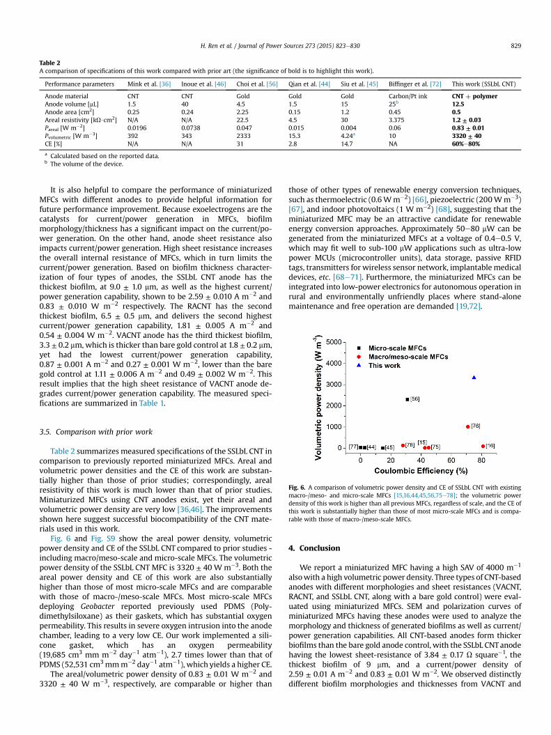
Table 2A comparison of specifications of this work compared with prior art (the significance of bold is to highlight this work).
Performance parameters Mink et al. [36] Inoue et al. [46] Choi et al. [56] Qian et al. [44] Siu et al. [45] Biffinger et al. [72] This work (SSLbL CNT)
Anode material CNT CNT Gold Gold Gold Carbon/Pt ink CNT þ polymerAnode volume [mL] 1.5 40 4.5 1.5 15 25b 12.5Anode area [cm2] 0.25 0.24 2.25 0.15 1.2 0.45 0.5Areal resistivity [kU$cm2] N/A N/A 22.5 4.5 30 3.375 1.2 ± 0.03Pareal [W m�2] 0.0196 0.0738 0.047 0.015 0.004 0.06 0.83 ± 0.01Pvolumetric [W m�3] 392 343 2333 15.3 4.24a 10 3320 ± 40CE [%] N/A N/A 31 2.8 14.7 NA 60%e80%
a Calculated based on the reported data.b The volume of the device.
H. Ren et al. / Journal of Power Sources 273 (2015) 823e830 829
It is also helpful to compare the performance of miniaturizedMFCs with different anodes to provide helpful information forfuture performance improvement. Because exoelectrogens are thecatalysts for current/power generation in MFCs, biofilmmorphology/thickness has a significant impact on the current/po-wer generation. On the other hand, anode sheet resistance alsoimpacts current/power generation. High sheet resistance increasesthe overall internal resistance of MFCs, which in turn limits thecurrent/power generation. Based on biofilm thickness character-ization of four types of anodes, the SSLbL CNT anode has thethickest biofilm, at 9.0 ± 1.0 mm, as well as the highest current/power generation capability, shown to be 2.59 ± 0.010 A m�2 and0.83 ± 0.010 W m�2 respectively. The RACNT has the secondthickest biofilm, 6.5 ± 0.5 mm, and delivers the second highestcurrent/power generation capability, 1.81 ± 0.005 A m�2 and0.54 ± 0.004 W m�2. VACNT anode has the third thickest biofilm,3.3 ± 0.2 mm, which is thicker than bare gold control at 1.8 ± 0.2 mm,yet had the lowest current/power generation capability,0.87 ± 0.001 A m�2 and 0.27 ± 0.001 W m�2, lower than the baregold control at 1.11 ± 0.006 A m�2 and 0.49 ± 0.002 W m�2. Thisresult implies that the high sheet resistance of VACNT anode de-grades current/power generation capability. The measured speci-fications are summarized in Table 1.
Fig. 6. A comparison of volumetric power density and CE of SSLbL CNT with existingmacro-/meso- and micro-scale MFCs [15,16,44,45,56,75e78]; the volumetric powerdensity of this work is higher than all previous MFCs, regardless of scale, and the CE ofthis work is substantially higher than those of most micro-scale MFCs and is compa-rable with those of macro-/meso-scale MFCs.
3.5. Comparison with prior work
Table 2 summarizes measured specifications of the SSLbL CNT incomparison to previously reported miniaturized MFCs. Areal andvolumetric power densities and the CE of this work are substan-tially higher than those of prior studies; correspondingly, arealresistivity of this work is much lower than that of prior studies.Miniaturized MFCs using CNT anodes exist, yet their areal andvolumetric power density are very low [36,46]. The improvementsshown here suggest successful biocompatibility of the CNT mate-rials used in this work.
Fig. 6 and Fig. S9 show the areal power density, volumetricpower density and CE of the SSLbL CNT compared to prior studies -including macro/meso-scale and micro-scale MFCs. The volumetricpower density of the SSLbL CNT MFC is 3320 ± 40 W m�3. Both theareal power density and CE of this work are also substantiallyhigher than those of most micro-scale MFCs and are comparablewith those of macro-/meso-scale MFCs. Most micro-scale MFCsdeploying Geobacter reported previously used PDMS (Poly-dimethylsiloxane) as their gaskets, which has substantial oxygenpermeability. This results in severe oxygen intrusion into the anodechamber, leading to a very low CE. Our work implemented a sili-cone gasket, which has an oxygen permeability(19,685 cm3 mm m�2 day�1 atm�1), 2.7 times lower than that ofPDMS (52,531 cm3mmm�2 day�1 atm�1), which yields a higher CE.
The areal/volumetric power density of 0.83 ± 0.01 W m�2 and3320 ± 40 W m�3, respectively, are comparable or higher than
those of other types of renewable energy conversion techniques,such as thermoelectric (0.6Wm�2) [66], piezoelectric (200Wm�3)[67], and indoor photovoltaics (1 W m�2) [68], suggesting that theminiaturized MFC may be an attractive candidate for renewableenergy conversion approaches. Approximately 50e80 mW can begenerated from the miniaturized MFCs at a voltage of 0.4e0.5 V,which may fit well to sub-100 mW applications such as ultra-lowpower MCUs (microcontroller units), data storage, passive RFIDtags, transmitters for wireless sensor network, implantable medicaldevices, etc. [68e71]. Furthermore, the miniaturized MFCs can beintegrated into low-power electronics for autonomous operation inrural and environmentally unfriendly places where stand-alonemaintenance and free operation are demanded [19,72].
4. Conclusion
We report a miniaturized MFC having a high SAV of 4000 m�1
alsowith a high volumetric power density. Three types of CNT-basedanodes with different morphologies and sheet resistances (VACNT,RACNT, and SSLbL CNT, along with a bare gold control) were eval-uated using miniaturized MFCs. SEM and polarization curves ofminiaturized MFCs having these anodes were used to analyze themorphology and thickness of generated biofilms as well as current/power generation capabilities. All CNT-based anodes form thickerbiofilms than the bare gold anode control, with the SSLbL CNTanodehaving the lowest sheet-resistance of 3.84 ± 0.17 U square�1, thethickest biofilm of 9 mm, and a current/power density of2.59 ± 0.01 A m�2 and 0.83 ± 0.01 W m�2. We observed distinctlydifferent biofilm morphologies and thicknesses from VACNT and
H. Ren et al. / Journal of Power Sources 273 (2015) 823e830830
RACNT anodes, most likely attributable to the morphology of theCNT forest e consequently resulting in two different current/powerdensities with the VACNT anodes delivering substantially lowercurrent/power densities than RACNT anodes. The highest powerdensity of 3320 ± 40 W m�3 was obtained by the SSLbL CNT anode,more than 8.5 times the power densities reported by prior-art MFCsusing 2D and 3D nanostructured electrodes. A high CE of 60%e80%supports the use of MFCs for renewable energy conversion in low-power electronics applications.
Appendix A. Supplementary data
Supplementary data related to this article can be found at http://dx.doi.org/10.1016/j.jpowsour.2014.09.165.
References
[1] M.E. Himmel, S.-Y. Ding, D.K. Johnson, W.S. Adney, M.R. Nimlos, J.W. Brady,T.D. Foust, Science 315 (2007) 804e807.
[2] A.J. Ragauskas, C.K. Williams, B.H. Davison, G. Britovsek, J. Cairney, C.A. Eckert,W.J. Frederick, J.P. Hallett, D.J. Leak, C.L. Liotta, Science 311 (2006) 484e489.
[3] D.R. Bond, D.E. Holmes, L.M. Tender, D.R. Lovley, Science 295 (2002) 483e485.[4] S.K. Chaudhuri, D.R. Lovley, Nat. Biotechnol. 21 (2003) 1229e1232.[5] B.E. Logan, K. Rabaey, Science 337 (2012) 686e690.[6] B.E. Logan, B. Hamelers, R. Rozendal, U. Schr€oder, J. Keller, S. Freguia,
P. Aelterman, W. Verstraete, K. Rabaey, Environ. Sci. Technol. 40 (2006)5181e5192.
[7] K. Rabaey, W. Verstraete, Trends Biotechnol. 23 (2005) 291e298.[8] B.E. Logan, Appl. Microbiol. Biotechnol. 85 (2010) 1665e1671.[9] A. ElMekawy, S. Srikanth, K. Vanbroekhoven, H. De Wever, D. Pant, J. Power
Sources 262 (2014) 183e191.[10] D. Pant, D. Arslan, G. Van Bogaert, Y.A. Gallego, H. De Wever, L. Diels,
K. Vanbroekhoven, Environ. Technol. 34 (2013) 1935e1945.[11] K.B. Gregory, D.R. Lovley, Environ. Sci. Technol. 39 (2005) 8943e8947.[12] L. Lu, T. Huggins, S. Jin, Y. Zuo, Z.J. Ren, Environ. Sci. Technol. 48 (2014)
4021e4029.[13] L.M. Tender, S.A. Gray, E. Groveman, D.A. Lowy, P. Kauffman, J. Melhado,
R.C. Tyce, D. Flynn, R. Petrecca, J. Dobarro, J. Power Sources 179 (2008)571e575.
[14] B. Logan, Microbial Fuel Cells, John Wiley & Sons, Inc., Hoboken, New Jersey,2008.
[15] H. Liu, B.E. Logan, Environ. Sci. Technol. 38 (2004) 4040e4046.[16] K. Rabaey, N. Boon, S.D. Siciliano, M. Verhaege, W. Verstraete, Appl. Environ.
Microbiol. 70 (2004) 5373e5382.[17] Z. He, S.D. Minteer, L.T. Angenent, Environ. Sci. Technol. 39 (2005) 5262e5267.[18] M. Rosenbaum, F. Zhao, U. Schroder, F. Scholz, Angew. Chem. Int. Ed. 45 (2006)
6658e6661.[19] B.R. Ringeisen, E. Henderson, P.K. Wu, J. Pietron, R. Ray, B. Little, J.C. Biffinger,
J.M. Jones-Meehan, Environ. Sci. Technol. 40 (2006) 2629e2634.[20] R.H. Baughman, A.A. Zakhidov, W.A. de Heer, Science 297 (2002) 787e792.[21] S.W. Lee, N. Yabuuchi, B.M. Gallant, S. Chen, B.S. Kim, P.T. Hammond, Y. Shao-
Horn, Nat. Nanotechnol. 5 (2010) 531e537.[22] A.D. Taylor, M. Michel, R.C. Sekol, J.M. Kizuka, N.A. Kotov, L.T. Thompson, Adv.
Funct. Mater. 18 (2008) 3003e3009.[23] A.K. Geim, K.S. Novoselov, Nat. Mater. 6 (2007) 183e191.[24] X. Xie, G.H. Yu, N. Liu, Z.N. Bao, C.S. Criddle, Y. Cui, Energy & Environ. Sci. 5
(2012) 6862e6866.[25] L. Xiao, J. Damien, J. Luo, H.D. Jang, J. Huang, Z. He, J. Power Sources 208 (2012)
187e192.[26] Y. Qiao, C.M. Li, S.J. Bao, Q.L. Bao, J. Power Sources 170 (2007) 79e84.[27] X.-W. Liu, X.-F. Sun, Y.-X. Huang, G.-P. Sheng, S.-G. Wang, H.-Q. Yu, Energy &
Environ. Sci. 4 (2011) 1422e1427.[28] H.Y. Tsai, C.C. Wu, C.Y. Lee, E.P. Shih, J. Power Sources 194 (2009) 199e205.[29] J.E. Mink, M.M. Hussain, ACS Nano 7 (2013) 6921e6927.[30] A. Mehdinia, E. Ziaei, A. Jabbari, Electrochim. Acta 130 (2014) 512e518.[31] Y.-C. Yong, X.-C. Dong, M.B. Chan-Park, H. Song, P. Chen, ACS Nano 6 (2012)
2394e2400.[32] Z. He, J. Liu, Y. Qiao, C.M. Li, T.T.Y. Tan, Nano Lett. 12 (2012) 4738e4741.[33] H. Wang, G. Wang, Y. Ling, F. Qian, Y. Song, X. Lu, S. Chen, Y. Tong, Y. Li,
Nanoscale 5 (2013) 10283e10290.
[34] Y. Qiao, X.-S. Wu, C.-X. Ma, H. He, C.M. Li, RSC Adv. 4 (2014) 21788e21793.[35] H.-T. Chou, H.-J. Lee, C.-Y. Lee, N.-H. Tai, H.-Y. Chang, Bioresour. Technol. 169
(2014) 532e536.[36] J.E. Mink, J.P. Rojas, B.E. Logan, M.M. Hussain, Nano Lett. 12 (2012) 791e795.[37] S.K. Smart, A.I. Cassady, G.Q. Lu, D.J. Martin, Carbon 44 (2006) 1034e1047.[38] T. Sharma, A.L.M. Reddy, T.S. Chandra, S. Ramaprabhu, Int. J. Hydrogen Energy
33 (2008) 6749e6754.[39] L. Peng, S.J. You, J.Y. Wang, Biosens. Bioelectron. 25 (2010) 1248e1251.[40] Y. Fan, E. Sharbrough, H. Liu, Environ. Sci. Technol. 42 (2008) 8101e8107.[41] H. Wang, Z. Wu, A. Plaseied, P. Jenkins, L. Simpson, C. Engtrakul, Z. Ren,
J. Power Sources 196 (2011) 7465e7469.[42] S. Khilari, S. Pandit, M. Ghangrekar, D. Das, D. Pradhan, RSC Adv. 3 (2013)
7902e7911.[43] H. Ren, H.-S. Lee, J. Chae, Microfluid. Nanofluid. 13 (2012) 353e381.[44] F. Qian, M. Baum, Q. Gu, D.E. Morse, Lab Chip 9 (2009) 3076e3081.[45] C.P.B. Siu, M. Chiao, J. Microelectromech. Syst. 17 (2008) 1329e1341.[46] S. Inoue, E. Parra, A. Higa, Y. Jiang, P. Wang, C.R. Buie, J.D. Coates, L. Lin, Sens.
Actuators A Phys. 177 (2012) 30e36.[47] H. Hou, L. Li, Y. Cho, P. de Figueiredo, A. Han, PLoS One 4 (2009) e6570.[48] H. Richter, K. McCarthy, K.P. Nevin, J.P. Johnson, V.M. Rotello, D.R. Lovley,
Langmuir 24 (2008) 4376e4379.[49] Z.F. Ren, Z.P. Huang, J.W. Xu, J.H. Wang, P. Bush, M.P. Siegal, P.N. Provencio,
Science 282 (1998) 1105e1107.[50] K.S. Choi, Y.S. Cho, S.Y. Hong, J.B. Park, D.J. Kim, J. Eur. Ceram. Soc. 21 (2001)
2095e2098.[51] F.S. Gittleson, D.J. Kohn, X. Li, A.D. Taylor, ACS Nano 6 (2012) 3703e3711.[52] P. Parameswaran, C.I. Torres, H.S. Lee, R. Krajmalnik-Brown, B.E. Rittmann,
Biotechnol. Bioeng. 103 (2009) 513e523.[53] S. Oh, C. Daraio, L.H. Chen, T.R. Pisanic, R.R. Finones, S. Jin, J. Biomed. Mater.
Res. Part A 78 (2006) 97e103.[54] D.-H. Kim, P.P. Provenzano, C.L. Smith, A. Levchenko, J. Cell Biol. 197 (2012)
351e360.[55] Z. Ren, R.P. Ramasamy, S.R. Cloud-Owen, H. Yan, M.M. Mench, J.M. Regan,
Bioresour. Technol. 102 (2011) 416e421.[56] S. Choi, H.S. Lee, Y. Yang, P. Parameswaran, C.I. Torres, B.E. Rittmann, J. Chae,
Lab Chip 11 (2011) 1110e1117.[57] M. Zurita-Gotor, F.S. Gittleson, A.D. Taylor, J. Blawzdziewicz, Phys. Rev. B 87
(2013) 195449.[58] J.L. Tan, J. Tien, D.M. Pirone, D.S. Gray, K. Bhadriraju, C.S. Chen, Proc. Natl. Acad.
Sci. 100 (2003) 1484e1489.[59] Z. Ren, H. Yan, W. Wang, M.M. Mench, J.M. Regan, Environ. Sci. Technol. 45
(2011) 2435e2441.[60] D.Y. Lyon, F. Buret, T.M. Vogel, J.-M. Monier, Bioelectrochemistry 78 (2010)
2e7.[61] J.S. McLean, G. Wanger, Y.A. Gorby, M. Wainstein, J. McQuaid, S.i. Ishii,
O. Bretschger, H. Beyenal, K.H. Nealson, Environ. Sci. Technol. 44 (2010)2721e2727.
[62] P. Aelterman, W. Verstraete, Trends Biotechnol. 27 (2009) 168e178.[63] P. Clauwaert, P. Aelterman, L. De Schamphelaire, M. Carballa, K. Rabaey,
W. Verstraete, Appl. Microbiol. Biotechnol. 79 (2008) 901e913.[64] A. ElMekawy, H.M. Hegab, X. Dominguez-Benetton, D. Pant, Bioresour. Tech-
nol. 142 (2013) 672e682.[65] D.R. Bond, S.M. Strycharz-Glaven, L.M. Tender, C.I. Torres, ChemSusChem 5
(2012) 1099e1105.[66] J. Stevens, SAE Technical Paper 1999-01-2564, 1999, http://dx.doi.org/
10.4271/1999-01-2564.[67] S.J. Roundy, Doctoral Dissertation, University of California, 2003.[68] R. Vullers, R. van Schaijk, I. Doms, C. Van Hoof, R. Mertens, Solid-State Elec-
tron. 53 (2009) 684e693.[69] M. Seok, S. Hanson, Y.S. Lin, Z. Foo, D. Kim, Y. Lee, N. Liu, D. Sylvester,
D. Blaauw, in: IEEE, 2008, pp. 188e189.[70] M. Hempstead, N. Tripathi, P. Mauro, G.Y. Wei, D. Brooks, in: IEEE, 2005, pp.
208e219.[71] V. Pillai, H. Heinrich, D. Dieska, P.V. Nikitin, R. Martinez, K.V.S. Rao, IEEE Trans.
Circuits Syst. I Reg. Pap. 54 (2007) 1500e1512.[72] J.C. Biffinger, R. Ray, B. Little, B.R. Ringeisen, Environ. Sci. Technol. 41 (2007)
1444e1449.[73] D.R. Bond, D.R. Lovley, Appl. Environ. Microbiol. 69 (2003) 1548e1555.[74] H.J. Kim, H.S. Park, M.S. Hyun, I.S. Chang, M. Kim, B.H. Kim, Enzyme Microb.
Technol. 30 (2002) 145e152.[75] H. Liu, S. Cheng, L. Huang, B.E. Logan, J. Power Sources 179 (2008) 274e279.[76] Y. Fan, H. Hu, H. Liu, J. Power Sources 171 (2007) 348e354.[77] M. Chiao, K.B. Lam, L. Lin, J. Micromech. Microeng. 16 (2006) 2547.[78] T. Shimoyama, S. Komukai, A. Yamazawa, Y. Ueno, B.E. Logan, K. Watanabe,
Appl. Microbiol. Biotechnol. 80 (2008) 325e330.