Embed Size (px)
Citation preview
Journal of Petroleum Science and Engineering 80 (2012) 53–60
Contents lists available at SciVerse ScienceDirect
Journal of Petroleum Science and Engineering
j ourna l homepage: www.e lsev ie r .com/ locate /pet ro l
Coupled THMC modeling of CO2 injection by finite element methods
Shunde Yin a,⁎, Maurice B. Dusseault b, Leo Rothenburg c
a Department of Chemical & Petroleum Engineering, University of Wyoming, Laramie, WY, 82071, United Statesb Department of Earth & Environmental Sciences, University of Waterloo, Waterloo, ON, Canada N2L 3G1c Department of Civil & Environmental Engineering, University of Waterloo, Waterloo, ON, Canada N2L 3G1
⁎ Corresponding author.E-mail addresses: [email protected] (S. Yin), mauriced
(M.B. Dusseault), [email protected] (L. Rothenburg)
0920-4105/$ – see front matter © 2011 Elsevier B.V. Alldoi:10.1016/j.petrol.2011.10.008
a b s t r a c t
a r t i c l e i n f oArticle history:Received 20 July 2010Accepted 18 October 2011Available online 26 October 2011
Keywords:petroleum geomechanicsporomechanicscarbon dioxide (CO2) injectionreactive solute transportmineral dissolution and precipitationfinite element methods (FEM)
Geological CO2 sequestration has been proposed to mitigate greenhouse gas emissions. Massive CO2 injectioninto subsurface formation involves interactions among pressure and temperature change, chemical reactions,solute transport, and the mechanical response of the rock; this is a coupled thermal–hydraulic–mechanical–chemical (THMC) process. Numerical modeling of CO2 injection around the wellbore area can provide infor-mation such as changes in rock properties as well as stress and pressure changes, and this helps better predictinjectivity evolution and leakage risk. In this paper, a fully coupled THMC model based on finite elementmethods is presented to analyze the transient stress, pressure, temperature and chemical solute concentrationchanges simultaneously around an injection well. To overcome these numerical oscillations in solvingthe transient advection–diffusion equations involved in the heat transfer and solute transport processes, weemploy a stabilized finite element approach, the subgrid scale/gradient subgrid scale method (SGS/GSGS). Ahypothetical numerical experiment on CO2 saturated water injection into a carbonate aquifer is conductedand preliminary results show that the fully coupled model can successfully analyze stress and pressurechanges in the rock around a wellbore subjected to thermal and chemical effects.
© 2011 Elsevier B.V. All rights reserved.
1. Introduction
Massive CO2 sequestration is proposed to mitigate greenhousegas emissions; salt caverns, depleted oil and gas reservoirs, anddeep saline aquifers have been considered as medium- to long-term (100–10,000 yr) geological sequestration media (Bachu andStewart, 2002). It has been suggested that 7 Gt of CO2 might besequestered every year, approximately 30% of annual anthropogenicCO2 emissions (Gessinger, 1997). Injection of such large amountsof CO2 requires suitable strata injectivity to keep costs to a reason-able level and also requires well and cap-rock integrity to reduceleakage risk (Streit and Hillis, 2004). This demands a better under-standing of permeability alterations and a clear description of stressand pressure changes in the storage formation and cap-rock duringinjection.
Massive CO2 injection into salt caverns, aquifers or depleted hy-drocarbon reservoirs induces a range of strongly coupled thermal, hy-draulic, mechanical and chemical processes (THMC) including heattransfer, multiphase fluid flow, geomechanical response (strains andstresses), solute transport, and geochemical reactions between the
@uwaterloo.ca.
rights reserved.
fluids and formation minerals. Researchers are making efforts towardfully coupled THMC modeling of CO2 injection from different degreesand combinations of coupling among thermal, hydraulic, mechanicaland chemical effects (Andre et al., 2007; Bachu and Dusseault, 2005;Bachu and Rothenburg, 2003; Celia and Nordbotten, 2009;Chalaturnyk and Gunter, 2004; Class et al., 2009; Comerlati et al.,2003; Dusseault et al., 2004; Hawkes et al., 2004; Izgec et al., 2008;Johnson et al., 2005; Kumar et al., 2005; Le Gallo et al., 2006;Lichtner and Lu, 2006; Nghiem et al., 2004; Prévost et al., 2005;Pruess et al., 2003; Rutqvist and Tsang, 2005; Rutqvist et al., 2002,Rutqvist et al., 2006; Xu et al., 2003). The very few fully-coupledTHMC models have addressed the large-scale problem, while thewellbore scale has not been paid much attention (Cailly et al., 2005;Gaus et al., 2008). To predict effectively the potential for hydraulicfracturing and shear failure, useful information for injection designand leakage prevention, it is necessary to identify the stressesand pressure change around the injection well. Since both CO2 in-jection in greenhouse gas storage and water/gas injection inpetroleum industry involve petroleum boreholes, within a generalpetroleum geomechanics perspective (Dusseault, 1999, 2003a,b),we use a fully-coupled THMC model to analyze stress and pressurechanges in the rock around a borehole during CO2 injection. Heattransfer, fluid flow, geomechanics behavior and reactive chemicaltransport are solved simultaneously in the mathematical modelpresented. Due to the complexity of the problem, we restrict our
54 S. Yin et al. / Journal of Petroleum Science and Engineering 80 (2012) 53–60
model to single phase flow and elastic porous media in this prelim-inary study.
In Section 2 we introduce the basic ideas behind fully-coupledTHMCmodeling during CO2 injection and corresponding formulationsby finite element methods (FEM). A simple FEM verification exampleis given in Section 3, a hypothetical numerical experiment on CO2
saturated water injection into a carbonate aquifer is conducted inSection 4, and conclusions are given in Section 5.
2. Fully coupled THMC modeling framework for CO2 injectionby FEM
Fully coupled THMC modeling of CO2 injection integrates theoriesof poroelasticity, thermoelasticity, elastoplasticity, and reactive solutetransport (Bear, 1988; Biot, 1941; Charlez, 1997; Coussy, 1995;Detournay and Cheng, 1993; Steefel and Lasaga, 1994; Zimmerman,1991). This combination allows us to address situations of strongcoupling among thermal flux, reactive solute transport, fluid flow,and porous medium deformations.
Based on thermoporoelastic theory for single phase fluid flowthrough deformable porous media, a general equilibrium equation interms of effective stress can be written as (Lewis and Schrefler,1998; Yin et al., 2010):
G∇2uþ Gþ λð Þ∇divu− 1− KKm
� �∇p−Kβs∇T ¼ 0 ð1Þ
G and λ are the Lamé elastic constants, u, p and T denote dis-placement, pore pressure and temperature respectively. βs is thevolumetric thermal expansion coefficient of the skeleton, and Kand Km are bulk moduli for the bulk skeleton and the matrix mineralrespectively.
The general form of the continuity equation for fluid flow, incorpo-rating Darcy's Law, can be expressed as follows (Lewis and Schrefler,1998; Yin et al., 2010):
∇T − kμ∇p
� �þ α−ϕ
Kmþ ϕKw
� � ∂p∂t þ α
∂ε∂t − α−ϕð Þβs þ ϕβw½ � ∂T∂t ¼ 0 : ð2Þ
whereα is Biot's coefficient, equal to 1.0-K/Km, k is the permeability ofthe porous medium, ϕ is the porosity and μ is the viscosity of the fluid.βw is the volumetric thermal expansion coefficient of the fluid. Thepermeability is updated based on the porosity change at each timestep after the temporal discretization introduced later for the wholesystem equation.
Then the general form of the energy balance equation, includingthe thermal convection and thermal conduction terms, can beexpressed as follows (Lewis and Schrefler, 1998; Yin et al., 2010):
∇T −λT∇T½ � þ ρwcwv∇T þ T 1−ϕð Þcsρs
Kmþ ϕcw
ρw
Kw
� � ∂p∂t
þ −ϕcwρwβwT− 1−ϕð ÞρscsβsT þ 1−ϕð Þρscs þ ϕρwcw½ � ∂T∂t þ Qh ¼ 0:
ð3Þ
Here, λT is the porous medium thermal conductivity, cl is the spe-cific heat capacity (the subscript l represents the solid, s, and water,w), ρl is the density, Qh is an external sink or source, and, as before,v is the Darcy velocity. In this work, the change of density and viscos-ity of fluids with temperature is ignored. For a particular problem,the specific boundary condition can be incorporated when solvingEq. (3).
Finally, considering that there are N aqueous species and M min-eral species involved in the chemical reactions between the fluid
and rock during CO2 injection, the general form of the equationfor solute transport of ith aqueous species, including both the solutediffusion and convection terms, is written as follows:
∇T Di∇Cið Þ þ ϕ∂Ci
∂t þ vw∇Ci ¼ Ri ; i ¼ 1;⋯;N ð4Þ
where Ci is aqueous phase concentration of the ith species definedas moles of species per unit volume of solution, Di is the dispersioncoefficient, Ri is the reaction rate, and vw is the Darcy velocity of thefluid. The general form of the continuity equation for the jth speciesin the solid phase is written as follows:
∂Cj
∂t ¼ Rj ; j ¼ 1;⋯;M ð5Þ
where Cj is the solid phase concentration of the jth mineral speciesdefined as moles of species per bulk volume of rock, and Rj is thereaction rate. The rate law for the mineral dissolution and precipita-tion reaction is:
Rj ¼ Ajkj 1−Qj
Keq; j
!ð6Þ
where Aj is the reactive surface area for mineral j, kj is the rate con-stant of mineral j, Keq, j is the chemical equilibrium constant for min-eral reaction j and Q j is the chemical affinity of mineral reaction j. Rj istaken as positive for precipitation and negative for dissolution. Therate of formation/consumption of the different aqueous species inEq. (5) is obtained from Ri=vij Rj, where vij is the stoichiometriccoefficient.
Approaches to solve the reactive transport equations above can bedivided in two groups: one-step methods and two-step methods. Inone-step methods, the solute transport and chemical reactions aresolved simultaneously (Celia et al., 1989; Lichtner and Lu, 2006;Miller and Benson, 1983; Steefel and Lasaga, 1994; Valocchi et al.,1981; White, 1995). In two-step methods, the solute transport andchemical reactions are solved separately (Barry et al., 1996; Bryantet al., 1986; Cederberg et al., 1985; Clement, 1997; Engesgaard andKipp, 1992; Herzer and Kinzelbach, 1989; Kirkner et al., 1984;Miller and Rabideau, 1993; Walsh et al., 1984; Walter et al., 1994;Wheeler and Dawson, 1988; Xu et al., 1999; Yeh and Tripathi, 1991;Zysset et al., 1994). Since the latter approach is recognized to bemore mathematically robust than the first one, a two-step methodis employed here to handle the reactive solute transport equations.With this two-step method, to couple the reactive solute transportto the other stress, pressure, and temperature fields mentioned previ-ously, the pure solute transport equation excluding the reaction rateterms will be solved with other equilibrium equations, mass balanceequations and energy balance equations simultaneously while thechemical reactions are solved immediately based on the solute con-centrations obtained. Then we have the new concentrations andthe induced porosity and permeability changes can be updated. Thechemical reactions can be solved by Newton–Raphson iterationand predictor–corrector methods (Xu et al., 1999; Zysset et al., 1994)whereas the fully coupled multi-field equations can be solved by the fi-nite element methods that are introduced in the following section.
Because of its power andflexibility, thefinite elementmethod (FEM)is widely applied in numerical modeling of petroleum geomechanicsrelated multi-field problems that couple stress and deformation, multi-phase flow, heat transfer, solute transport, etc. (Dusseault et al., 1998;Gambolati et al., 2001; Gutierrez and Lewis, 1998; Jing and Hudson,2002; Settari andMourits, 1998; Yin et al., 2009, 2010). Based on the tra-ditional Galerkin finite element method, the final matrix form of
0.0
0.2
0.4
0.6
0.8
1.0
0 0.05 0.1 0.15 0.2 0.25 0.3 0.35 0.4
x (m)
Rel
ativ
e C
once
ntra
tion
Species 1
Species 2
t = 50 hours
Species 3
Fig. 1. Relative concentration of species at t=50 h.
55S. Yin et al. / Journal of Petroleum Science and Engineering 80 (2012) 53–60
solution for the above equations after discretization can be expressedas follows:
M −Csw −CsT 0 0 00 Hww 0 0 0 00 0 HTT 0 0 00 0 0 HCC1 0 00 0 0 0 ⋱ 00 0 0 0 0 HCCN
26666664
37777775
upTC1⋮CN
8>>>>>><>>>>>>:
9>>>>>>=>>>>>>;
þ
0 0 0 0 0 0Cws Rww CwT 0 0 00 CTw RTT 0 0 00 0 0 RCC 0 00 0 0 0 ⋱ 00 0 0 0 0 RCC
26666664
37777775
utptTtC1t
⋮CNt
8>>>>>><>>>>>>:
9>>>>>>=>>>>>>;
¼
fu
fw
fT
fC1
⋮fCN
8>>>>>><>>>>>>:
9>>>>>>=>>>>>>;
ð7Þ
where [u, p, T, C1, …, CN]T and [ut, pt, Tt, C1t, …, CNt]T are the vectorsof unknown variables and corresponding time derivatives. [fu, fw, fT,fc1, …, fcN]T is the vector for the nodal loads, the flow source, theheat source, and the solute source. The explicit expressions of theabove matrices are listed in Appendix A.
To integrate the above equations with respect to time, linear inter-polation in time using a finite difference method is introduced, so theequations can be written as:
θM −θCsw −θCsT 0 0 0Cws θHww þ Rww CwT 0 0 00 CTw θHTT þ RTT 0 0 00 0 0 θHCC1 þ RCC 0 00 0 0 0 ⋱ 00 0 0 0 0 θHCCN þ RCC
26666664
37777775
ΔuΔpΔTΔC1
⋮ΔCN
8>>>>>><>>>>>>:
9>>>>>>=>>>>>>;
¼
Δfu
Δtfw−ΔtHwwpΔtfT−ΔtHTTT
ΔtfC1−ΔtHCC1C1
⋮ΔtfCN−ΔtHCCNCN
8>>>>>>><>>>>>>>:
9>>>>>>>=>>>>>>>;:
ð8Þ
The change in porosity (e.g., in Eqs. (2), (3) and (4)) and perme-ability of the rock because of mineral dissolution–precipitation isdetermined by (Nghiem et al., 2004):
ϕnþ1 ¼ ϕn−XMj¼1
Cj;nþ1
ρj−
Cj;n
ρj
!ð9Þ
knþ1 ¼ ϕ3nþ1 1:0−ϕnð Þ2
ϕ3n 1:0−ϕnþ1� �2 kn ð10Þ
whereϕn andϕn+1 is the porosity at the nth and (n+1)th time step; knand kn+1 is the permeability at the nth and (n+1)th time step; ρj is thedensity of mineral j; and, Cj,n and Cj,n+1 is the solid phase concentrationof mineral j at nth and (n+1)th time step. Eq. (10) is the empiricalKozeny-Carman equation linking porosity and permeability which hasbeenwidely used for clean porous sands over limited ranges of porositywithout plastic deformation phenomena such as grain crushing.
Although the finite element method (FEM) is a powerful methodof solving the coupled system, there remain certain forms of numeri-cal instability involved in the energy balance equation and solutecontinuity equations when solving transient advection–diffusionequations. One is the oscillatory instability in the computed tempera-ture or solute concentration fields under convection-dominant cir-cumstances, and the other is the instability in early time stepsduring the transient diffusion–convection problems. As pointed outby Idelsohn et al. (1996), there are actually two types of sharp gradi-ents implied in the transient advection–diffusion problem: one iscaused by high Peclet numbers, the other by sharp gradients whichappear during the initial small time steps because of the transient
solution. This sharp gradient, analogous to a shock front in a fluidmechanics problem, disappears after a few time steps if the problemis diffusion-dominated, but persists as the solution approachesthe stationary state if the problem is advection-dominated. The wayto eliminate the spurious oscillations is different when the sharpgradients are induced by the transient behavior than when they areproduced by the advective terms. To meet this challenge, we addressboth sources of numerical instability by using a stabilized finiteelement method, the subgrid scale/gradient subgrid scale (SGS/GSGS)method. For the details, please refer to (Harari and Hauke, 2007;Hauke and Doweidar, 2006; Yin et al., 2009, 2010).
3. Validation of the finite element model: reactive solute transport
Verification of the coupling of thermal effects, poroelasticityand solute transport in a FEM model has been addressed in previousarticles (Yin et al., 2009, 2010), so here the emphasis is placed on val-idation of the reactive transport module and its FEM implementation.The chosen validation problem deals with transport of three specieswith sorption and decay in a one-dimensional flow field, for whichprevious solutions are known (Lunn et al., 1996) and are used to verifythe reactive solute transport code (Clement et al., 1998). The modelequations involved in this specific case are:
R∂C1
∂t ¼ D∂2C1
∂z2−v
∂C1
∂z −k1C1 ð11Þ
∂C2
∂t ¼ D∂2C2
∂z2−v
∂C2
∂z −k2C2 þ k1C1 ð12Þ
∂C3
∂t ¼ D∂2C3
∂z2−v
∂C3
∂z −k3C3 þ k2C2 ð13Þ
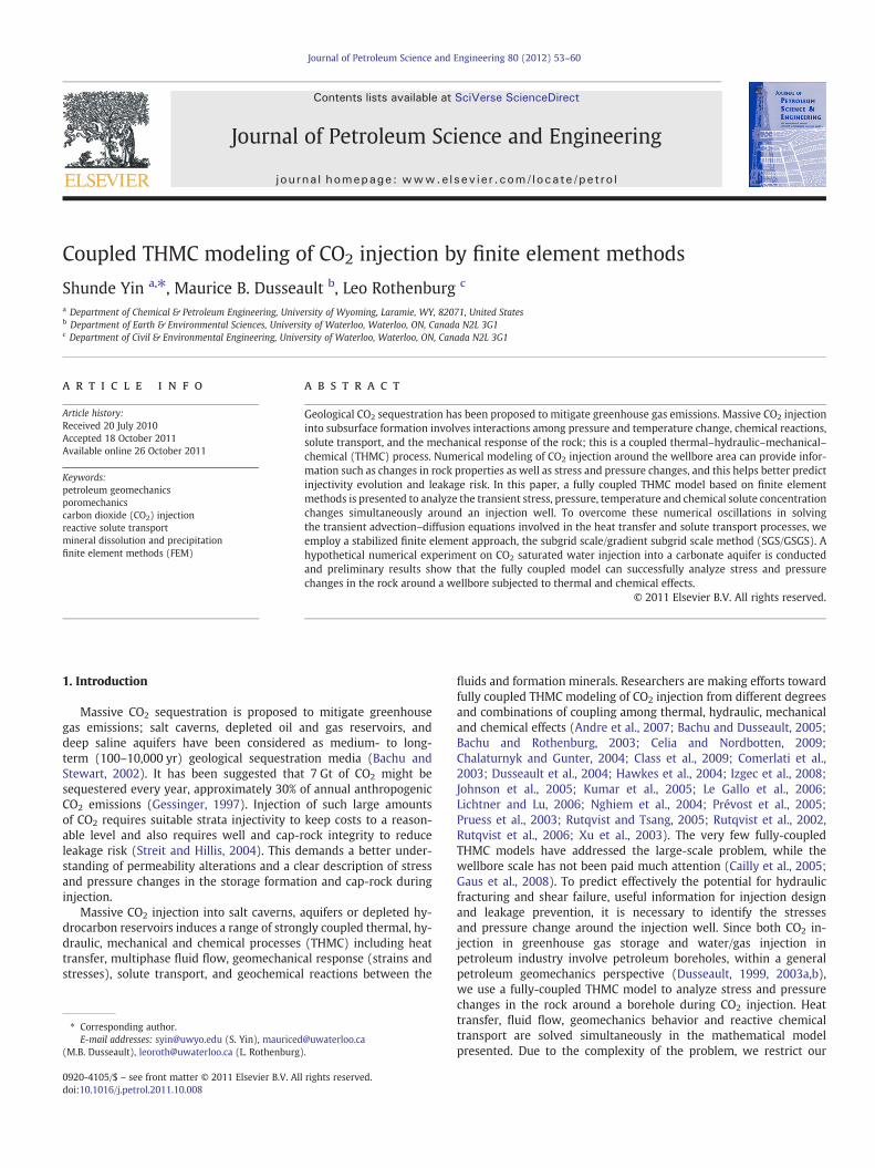
where C1, C2, and C3 are concentrations of species. Also,D is the disper-sion coefficient, v is the fluid velocity, k1, k2, and k3 are the speciesreaction rates, and R is the retardation coefficient. The values of the pa-rameters chosen for the problem are: D=0.018 cm2/h, v=0.1 cm/h,k1=0.05 h−1, k2=0.03 h−1, k3=0.02 h−1, and R=2.0. Further-more, the length of the one-dimensional column is 40 cm. The initialconcentrations of the three species are zero, and the boundary condi-tion at the inlet is set with C10=1.0, C20=0.0, and C30=0.0, whilea no-flux boundary condition is set at the exit boundary. The flow isassumed to be steady-state with constant velocity.
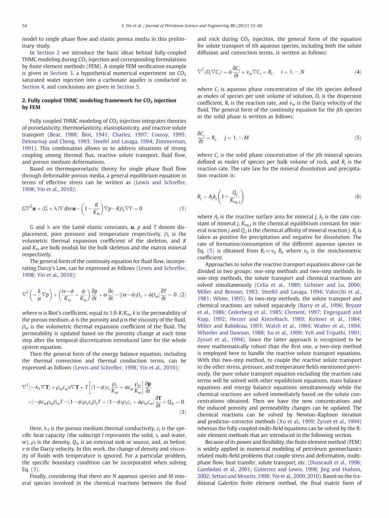
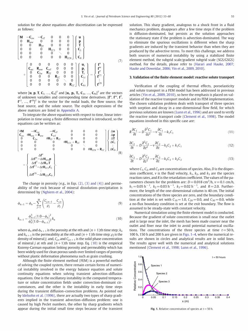
Numerical simulation using the finite element model is conducted.Because the gradient of solute concentration is small near the outletand is large near the inlet, the mesh has been made coarser near theoutlet and finer near the inlet to avoid potential numerical oscilla-tions. The concentrations of the three species at time t=50 h,100 h, 150 h and 200 h are given in Figs. 1–4, where the numerical re-sults are shown in circles and analytical results are in solid lines.The results agree well with the numerical and analytical solutionsmentioned (Clement et al., 1998; Lunn et al., 1996).
0.0
0.2
0.4
0.6
0.8
1.0
0 0.05 0.1 0.15 0.25 0.3 0.35 0.4
x (m)
Rel
ativ
e C
once
ntra
tion
Species 3
Species 1
Species 2
t = 100 hours
0.2
Fig. 2. Relative concentration of species at t=100 h.
0.0
0.2
0.4
0.6
0.8
1.0
x (m)
Rel
ativ
e C
once
ntra
tion
Species 1
Species 2
t = 200 hours
Species 3
0 0.05 0.1 0.15 0.2 0.25 0.3 0.35 0.4
Fig. 4. Relative concentration of species at t=200 h.
r
pi
σhy
σhx X
Y
r
pi
σ
σX
Y
r
pi
σhy
σhx X
Y
rw
pi
σ
σX
Y
56 S. Yin et al. / Journal of Petroleum Science and Engineering 80 (2012) 53–60
4. Numerical experiments: injection of CO2 saturated water into acarbonate aquifer
In this hypothetical numerical experiment, we suppose injectionof CO2 saturated water into a carbonate aquifer. The aquifer formationis composed of pure calcite (CaCO3), and the porosity is 0.25.The aquifer is at a depth of 1500 m and subject to a vertical stressσv=3.2×10⁴ kPa and horizontal far-field stresses of σhx=σhy=2.2×10⁴ kPa as shown in Fig. 5. The initial pore pressure isp0=1.4×10⁴ kPa, maintained constant at the far-field boundary.The radius of the open hole well is rw=0.127 m.
During the injection of the CO2-saturated water, the injection pres-sure is maintained at pi=2.0×10⁴ kPa, at a temperature Ti=10 °C. InCO2-saturated water, CO2 is assumed to be dissolved in the liquidphase; H2CO3 is formed and thus leads to the fast reactions as follows:
CO2 þ H2O⇒H2CO3 ð14Þ
H2CO3⇔Hþ þ HCO−3 : ð15Þ
Since this reaction is almost instantaneous compared to the disso-lution and precipitation of mineral, a boundary condition of H+ con-centration of 63.1 mol/m3maintained at the injection well is assumed(rather than a boundary condition of CO2 concentration). Then themajor reaction considered between the acidic solution and the rockmineral during the injection is:
CaCO3 þ Hþ⇔Ca2þ þ HCO−3 : ð16Þ
Suppose the initial concentrations of H+, Ca2+, and HCO3− are
1.0×10⁻⁴ mol/m3, 4.0 mol/m3, and 4.0 mol/m3, respectively, andthis is a chemical equilibrium state and is maintained at the far-fieldboundary by assuming that the chemical equilibrium constant ofthe reaction is 1.6×10⁵. The initial temperature of the aquifer is70 °C and is also maintained constant at the far-field boundary. Valuesof the other parameters are E=1.5×10⁶ kPa, v=0.30, Km=1.4×10⁶ kPa, Kw=1.0×10⁶ kPa, permeability k=0.987×10⁻¹⁶ m2, vis-cosity of water μ=1 cP, ρs=2.5×10³ kg/m3, ρw=1.0×10³ kg/m3,
0.0
0.2
0.4
0.6
0.8
1.0
x (m)
Rel
ativ
e C
once
ntra
tion
Species 3
Species 1
Species 2
t = 150 hours
0 0.05 0.1 0.15 0.25 0.3 0.40.350.2
Fig. 3. Relative concentration of species at t=150 h.
βs=2.0×10⁻⁵ K−1, βw=2.0×10⁻⁴ K−1, specific heat capacity ofsolid cs=0.4 kJ/kg-K, specific heat capacity of water cw=4.2 kJ/kg-K,heat conductivity λT=2.65 J/m-s-K, dispersion coefficient D=1.5×10⁻⁷ m2/s, rate constant of calcite dissolution or precipitation equalto 2.5×10⁻⁶ mol-m−2-s−1.
4.1. Fully coupled THMC solution
In this section, the fully coupled THMC solution is presented in-cluding stress, pore pressure, and temperature changes, as well asmineral dissolution/precipitation induced porosity and permeabilitychanges.
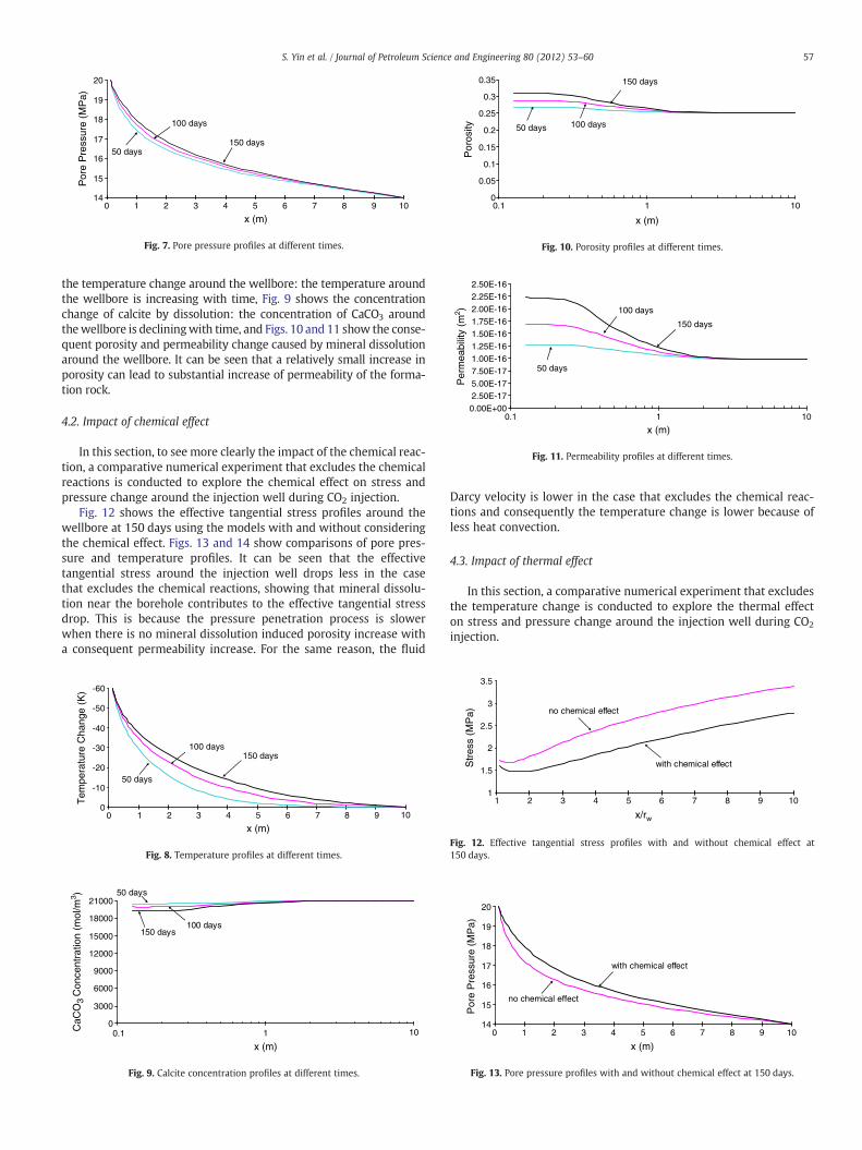
Fig. 6 shows the effective tangential stress profiles around thewellbore (all the profiles in this section and hereafter are along thex axis shown in Fig. 5) at different times computed by the stabilizedSGS/GSGS FEM. It can be seen that the effective tangential stressaround the wellbore is declining over the time under the combinedimpact of cooling and chemical reaction effects, which makes an in-duced hydraulic fracture more likely to take place (i.e. when σθ be-comes bp). Fig. 7 shows the pressure penetration into the formation:the pressure around the wellbore is increasing with time, Fig. 8 shows
Fig. 5. Geometry of the wellbore and far-field stresses.
1
1.5
2
2.5
3
3.5
x/rw
Str
ess
(MP
a)
50 days
100 days150 days
1 2 3 4 5 6 7 8 9 10
Fig. 6. Effective tangential stress profiles at different times.
14
15
16
17
18
19
20
x (m)
Por
e P
ress
ure
(MP
a)
150 days50 days
100 days
0 1 2 3 4 5 6 7 8 9 10
Fig. 7. Pore pressure profiles at different times.
0
0.05
0.1
0.15
0.2
0.25
0.3
0.35
1010.1
x (m)
Por
osity
150 days
100 days50 days
Fig. 10. Porosity profiles at different times.
0.00E+002.50E-175.00E-177.50E-171.00E-161.25E-161.50E-161.75E-162.00E-162.25E-162.50E-16
1010.1
x (m)
Per
mea
bilit
y (m
2 )
150 days
100 days
50 days
Fig. 11. Permeability profiles at different times.
57S. Yin et al. / Journal of Petroleum Science and Engineering 80 (2012) 53–60
the temperature change around the wellbore: the temperature aroundthe wellbore is increasing with time, Fig. 9 shows the concentrationchange of calcite by dissolution: the concentration of CaCO3 aroundthewellbore is decliningwith time, and Figs. 10 and 11 show the conse-quent porosity and permeability change caused by mineral dissolutionaround the wellbore. It can be seen that a relatively small increase inporosity can lead to substantial increase of permeability of the forma-tion rock.
4.2. Impact of chemical effect
In this section, to see more clearly the impact of the chemical reac-tion, a comparative numerical experiment that excludes the chemicalreactions is conducted to explore the chemical effect on stress andpressure change around the injection well during CO2 injection.
Fig. 12 shows the effective tangential stress profiles around thewellbore at 150 days using the models with and without consideringthe chemical effect. Figs. 13 and 14 show comparisons of pore pres-sure and temperature profiles. It can be seen that the effectivetangential stress around the injection well drops less in the casethat excludes the chemical reactions, showing that mineral dissolu-tion near the borehole contributes to the effective tangential stressdrop. This is because the pressure penetration process is slowerwhen there is no mineral dissolution induced porosity increase witha consequent permeability increase. For the same reason, the fluid
-60
-50
-40
-30
-20
-10
0
x (m)
Tem
pera
ture
Cha
nge
(K)
100 days150 days
50 days
0 1 2 3 4 5 6 7 8 9 10
Fig. 8. Temperature profiles at different times.
0
3000
6000
9000
12000
15000
18000
21000
1010.1
x (m)
CaC
O3 C
once
ntra
tion
(mol
/m3 ) 50 days
150 days100 days
Fig. 9. Calcite concentration profiles at different times.
Darcy velocity is lower in the case that excludes the chemical reac-tions and consequently the temperature change is lower because ofless heat convection.
4.3. Impact of thermal effect
In this section, a comparative numerical experiment that excludesthe temperature change is conducted to explore the thermal effecton stress and pressure change around the injection well during CO2
injection.
1
1.5
2
2.5
3
3.5
x/rw
Str
ess
(MP
a) no chemical effect
with chemical effect
1 2 3 4 5 6 7 8 9 10
Fig. 12. Effective tangential stress profiles with and without chemical effect at150 days.
14
15
16
17
18
19
20
x (m)
Por
e P
ress
ure
(MP
a)
with chemical effect
no chemical effect
0 1 2 3 4 5 6 7 8 9 10
Fig. 13. Pore pressure profiles with and without chemical effect at 150 days.
-60
-50
-40
-30
-20
-10
0
x (m)
Tem
pera
ture
Cha
nge
(K)
with chemical effect
no chemical effect
0 1 2 3 5 6 7 8 9 104
Fig. 14. Temperature profiles with and without chemical effect at 150 days.
1
1.5
2
2.5
3
x/rw
Str
ess
(MP
a) no thermal effect
with thermal effect
1 2 3 4 7 8 9 105 6
Fig. 15. Effective tangential stress profiles with and without thermal effect at 150 days.
0
10
20
30
40
50
60
70
x (m)
Con
cent
ratio
n of
H+
(mol
/m3 )
by stabilized finite element method
by Galerkin finite element method
0 1 2 3 4 5 6 7 8 9 10
Fig. 17. H+ concentration profiles generated by Galerkin FEM and stabilized FEM.
58 S. Yin et al. / Journal of Petroleum Science and Engineering 80 (2012) 53–60
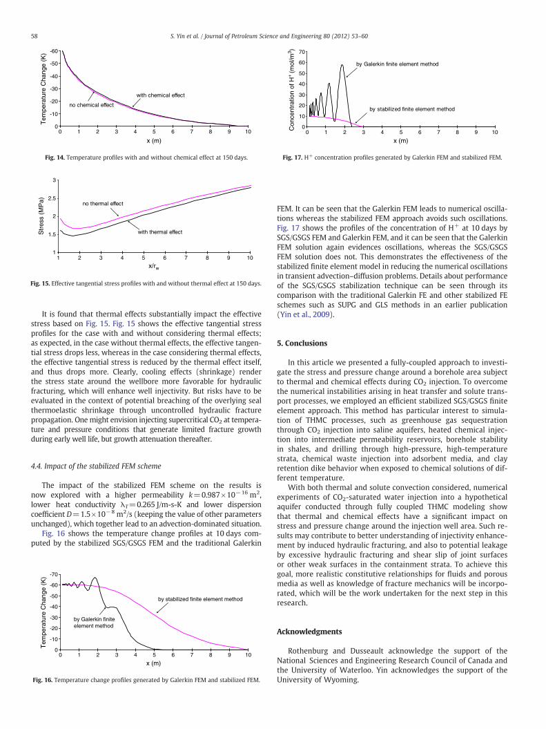
It is found that thermal effects substantially impact the effectivestress based on Fig. 15. Fig. 15 shows the effective tangential stressprofiles for the case with and without considering thermal effects;as expected, in the case without thermal effects, the effective tangen-tial stress drops less, whereas in the case considering thermal effects,the effective tangential stress is reduced by the thermal effect itself,and thus drops more. Clearly, cooling effects (shrinkage) renderthe stress state around the wellbore more favorable for hydraulicfracturing, which will enhance well injectivity. But risks have to beevaluated in the context of potential breaching of the overlying sealthermoelastic shrinkage through uncontrolled hydraulic fracturepropagation. One might envision injecting supercritical CO2 at tempera-ture and pressure conditions that generate limited fracture growthduring early well life, but growth attenuation thereafter.
4.4. Impact of the stabilized FEM scheme
The impact of the stabilized FEM scheme on the results isnow explored with a higher permeability k=0.987×10⁻¹⁶ m2,lower heat conductivity λT=0.265 J/m-s-K and lower dispersioncoefficient D=1.5×10⁻⁸ m2/s (keeping the value of other parametersunchanged), which together lead to an advection-dominated situation.
Fig. 16 shows the temperature change profiles at 10 days com-puted by the stabilized SGS/GSGS FEM and the traditional Galerkin
-70
-60
-50
-40
-30
-20
-10
0
x (m)
Tem
pera
ture
Cha
nge
(K)
by stabilized finite element method
by Galerkin finiteelement method
0 1 2 3 4 5 6 7 8 9 10
Fig. 16. Temperature change profiles generated by Galerkin FEM and stabilized FEM.
FEM. It can be seen that the Galerkin FEM leads to numerical oscilla-tions whereas the stabilized FEM approach avoids such oscillations.Fig. 17 shows the profiles of the concentration of H+ at 10 days bySGS/GSGS FEM and Galerkin FEM, and it can be seen that the GalerkinFEM solution again evidences oscillations, whereas the SGS/GSGSFEM solution does not. This demonstrates the effectiveness of thestabilized finite element model in reducing the numerical oscillationsin transient advection–diffusion problems. Details about performanceof the SGS/GSGS stabilization technique can be seen through itscomparison with the traditional Galerkin FE and other stabilized FEschemes such as SUPG and GLS methods in an earlier publication(Yin et al., 2009).
5. Conclusions
In this article we presented a fully-coupled approach to investi-gate the stress and pressure change around a borehole area subjectto thermal and chemical effects during CO2 injection. To overcomethe numerical instabilities arising in heat transfer and solute trans-port processes, we employed an efficient stabilized SGS/GSGS finiteelement approach. This method has particular interest to simula-tion of THMC processes, such as greenhouse gas sequestrationthrough CO2 injection into saline aquifers, heated chemical injec-tion into intermediate permeability reservoirs, borehole stabilityin shales, and drilling through high-pressure, high-temperaturestrata, chemical waste injection into adsorbent media, and clayretention dike behavior when exposed to chemical solutions of dif-ferent temperature.
With both thermal and solute convection considered, numericalexperiments of CO2-saturated water injection into a hypotheticalaquifer conducted through fully coupled THMC modeling showthat thermal and chemical effects have a significant impact onstress and pressure change around the injection well area. Such re-sults may contribute to better understanding of injectivity enhance-ment by induced hydraulic fracturing, and also to potential leakageby excessive hydraulic fracturing and shear slip of joint surfacesor other weak surfaces in the containment strata. To achieve thisgoal, more realistic constitutive relationships for fluids and porousmedia as well as knowledge of fracture mechanics will be incorpo-rated, which will be the work undertaken for the next step in thisresearch.
Acknowledgments
Rothenburg and Dusseault acknowledge the support of theNational Sciences and Engineering Research Council of Canada andthe University of Waterloo. Yin acknowledges the support of theUniversity of Wyoming.
59S. Yin et al. / Journal of Petroleum Science and Engineering 80 (2012) 53–60
Appendix A
M ¼ ∫VBTDBdV
Csw ¼ ∫V
BTi�BTDi
3Km
� �NdV
CsT ¼ ∫VBTDi
βs
3NdV
Hww ¼ ∫Vð∇NÞT k
μð∇NÞdV
Cws ¼ ∫VNT iT� iTD
3Km
!BdV
Rww ¼ ∫VNT ϕ
Kwþ 1−ϕ
Km− 1
ð3KmÞ2iTDi
� �� �NdV
CwT ¼ ∫VNT ϕβw− 1−ϕ− 1
9KmiTDi
� �βs
� �NdV
CTw ¼ ∫VNT 1−ϕð Þρscs
Kmþ ϕρwcw
Kw
� �TNdV
RTT ¼ ∫VNT½−ϕρwcwβwT− 1−ϕð ÞρscsβsT þ 1−ϕð Þρscs þ ϕρwcw�NdV
HTT ¼ ∫V
ð∇NÞTλT ð∇NÞ þ NTρwcwkμp;i∇N
� �dV
RCC ¼ ∫VNTϕNdV
HCC1 ¼ ∫Vð∇NÞTD1ð∇NÞdVþ ∫
VNT k
μp;i
� �ð∇NÞdV
HCCN ¼ ∫Vð∇NÞTDNð∇NÞdVþ ∫
VNT k
μp;i
� �ð∇NÞdV
References
Andre, L., Audigane, P., Azaroual, M., Menjoz, A., 2007. Numerical modeling of fluid–rock chemical interactions at the supercritical CO2–liquid interface during CO2 in-jection into a carbonate reservoir, the Dogger aquifer (Paris Basin, France). EnergyConvers. Manage. 48, 1782–1797.
Bachu, S., Dusseault, M.B., 2005. Underground injection of carbon dioxide in saltbeds. In: Tsang, C.F., Apps, J.A. (Eds.), Injection Science and Technology. Elsevier,pp. 637–648.
Bachu, S., Rothenburg, L., 2003. Carbon dioxide sequestration in salt caverns: capacityand long term fate. Proceedings of the Second Annual Conference on CarbonDioxide Sequestration. Alexandria, VA.
Bachu, S., Stewart, S., 2002. Geological sequestration of anthropogenic carbon dioxidein the Western Canada Sedimentary Basin Suitability analysis. J. Can. Pet. Technol.41, 32–40.
Barry, D.A., Bajracharya, K., Miller, C.T., 1996. Alternative split-operator approachfor solving chemical reaction/groundwater transport models. Adv. Water Res. 19,261–275.
Bear, J., 1988. Dynamics of Fluids in Porous Media. Dover, New York.Biot, M.A., 1941. General theory of three-dimensional consolidation. J. Appl. Phys. 12,
155–164.Bryant, S.L., Schechter, R.S., Lake, L.W., 1986. Interactions of precipitation/dissolutionwave
and ion exchange in flow through permeable media. AIChE J. 32 (5), 751–764.Cailly, B., Le Thiez, P., Egermann, P., Audibert, A., Vidal-Gilbert, S., Longaygue, X., 2005.
Geological storage of CO2: a state-of-the-art of injection processes and technolo-gies. Oil Gas Sci. Technol. 60, 517–525.
Cederberg, G.A., Street, R.L., Leckie, J.O., 1985. A groundwater mass transport and equi-librium model for multicomponent system. Water Resour. Res. 21 (8), 1095–1104.
Celia, M.A., Kindred, J.S., Herrera, I., 1989. Contaminant transport and biodegradation,1, a numerical model for reactive transport in porous media. Water Resour. Res.25, 1141–1148.
Celia, M.A., Nordbotten, J.M., 2009. Practical modeling approaches for geologicalstorage of carbon dioxide. Ground Water 47, 627–638.
Chalaturnyk, R., Gunter, W.D., 2004. Geological storage of CO2: time frames, monitoringand verification. Proceedings of the 7th International Conference on GreenhouseGas Control Technologies, pp. 623–632.
Charlez, P.A., 1997. Rock Mechanics, Petroleum Applications, 2. Edition. Technip, Paris.Class, H., Ebigbo, A., Helmig, R., Dahle, H., Nordbotten, J.M., Celia, M.A., Audigane, P.,
Darcis, M., Ennis-King, J., Fan, Y., Flemisch, B., Gasda, S., Krug, S., Labregere, D.,Min, J., Sbai, A., Thomas, S., Trenty, L., 2009. A benchmark study on problems relatedto CO2 storage in geologic formations. Comput. Geosci. 13, 469–481.
Clement, T.P., 1997. RT3D—amodular computer code for simulating reactivemulti-speciestransport in 3-dimensional groundwater systems. Battelle Pacific Northwest NationalLaboratory Research Report, PNNL-SA-28967.
Clement, T.P., Sun, Y., Hooker, B.S., Petersen, J.N., 1998. Modeling multispecies reactivetransport in ground water. Ground Water Monit. Rem. 18, 79–92.
Comerlati, A., Ferronato, M., Gambolati, G., Putti, M., Teatini, P., 2003. Fluid dynamicand geomechanical effects of CO2 sequestration below the Venice Lagoon. Environ.Eng. Geosci. XII, 211–226.
Coussy, O., 1995. Mechanics of Porous Continua. Wiley, New York.Detournay, E., Cheng, A.H.-D., 1993. Fundamentals of poroelasticity. In: Hudson, J.A.
(Ed.), Comprehensive Rock Engineering: Principles, Practice and Projects, 2.Pergamon, Oxford, pp. 113–171.
Dusseault, M.B., Wang, Y., Simmons, J.V., 1998. Induced stresses near a fire flood front.AOSTRA J. Res. 4, 153–170.
Dusseault, M.B., 1999. Petroleum geomechanics: excursions into coupled behavior.J. Can. Pet. Technol. 38, 10–14.
Dusseault, M.B., Rothenburg, L., Bachu, S., 2004. Sequestration of CO2 in salt caverns.J. Can. Pet. Technol. 43, 49–55.
Dusseault, M.B., 2003a. Coupled processes and petroleum geomechanics. Proceedingsof Geoproc 2003, International Conference on Coupled THMC Processes in PorousMedia, Stockholm, Sweden, pp. 44–57.
Dusseault, M.B., 2003b. Coupled thermo-mechano-chemical processes in shales: thepetroleum borehole. Proceedings of Geoproc 2003. International Conference onCoupled THMC Processes in Porous Media. Stockholm, Sweden, pp. 571–578.
Engesgaard, P., Kipp, K.L., 1992. A geochemical transport model for redox-controlledmovement ofmineral fronts in groundwater flow systems: a case of nitrate removalby oxidation of pyrite. Water Resour. Res. 28, 2829–2843.
Gambolati, G., Ferronato, M., Teatini, P., Deidda, R., Lecca, G., 2001. Finite element analysisof land subsidence above depleted reservoirs with pore pressure gradient and totalstress formulations. Int. J. Numer. Anal. Methods Geomech. 25, 307–327.
Gaus, I., Audigane, P., André, L., Lions, J., Jacquemet, N., Durst, P., Czernichowski-Lauriol,I., Azaroual, M., 2008. Geochemical and solute transport modelling for CO2 storage,what to expect from it? Int. J. Greenhouse Gas Control 2, 605–625.
Gessinger, G., 1997. Lower CO2 emission through better technology. Energy Convers.Manage. 38, S25–S30 Suppl.
Gutierrez, M., Lewis, R.W., 1998. The Role of Geomechanics in Reservoir Simulation. SPE47392, the 1998 SPE/ISRM Rock Mechanics in Petroleum Engineering Conference,Trondheim.
Hauke, G., Doweidar, M.H., 2006. Fourier analysis of semi-discrete and space-timestabilized methods for the advective–diffusive–reactive equation: III. SGS/GSGS.Comput. Meth. Appl. Mech. Eng. 195, 6158–6176.
Harari, I., Hauke, G., 2007. Semidiscrete formulations for transient transport at smalltime steps. Int. J. Numer. Methods Fluids 54, 731–743.
Hawkes, C.D., McLellan, P.J., Zimmer, U., Bachu, S., 2004. Geomechanical factorsaffecting geological storage of CO2 in depleted oil and gas reservoirs: risksand mechanisms. Proceedings of Gulf Rocks 2004, the 6th North AmericaRock Mechanics Symposium (NARMS): Rock Mechanics across Borders andDisciplines, Houston, Texas, June 5–9.
Herzer, J., Kinzelbach, W., 1989. Coupling of transport and chemical processes innumerical transport models. Geoderma 44, 115–127.
Idelsohn, S.R., Heinrich, J.C., Onate, E., 1996. Petrov–Galerkinmethods for the transient advec-tive–diffusive equationwith sharp gradients. Int. J. Numer.Methods Eng. 39, 1455–1473.
Izgec, O., Demiral, B., Bertin, H., Akin, S., 2008. CO2 injection into saline carbonateaquifer formations II: comparison of numerical simulations to experiments.Transp. Porous Media 73, 57–74.
Jing, L., Hudson, J.A., 2002. Numerical methods in rock mechanics. Int. J. Rock Mech.Min. Sci. 39, 409–427.
Johnson, J.W., Nitao, J.J., Morris, J.P., 2005. Reactive transport modeling of cap rockintegrity during natural and engineered CO2 storage. In: Thomas, D.C., Benson,S.M. (Eds.), Carbon Dioxide Capture for Storage in Deep Geologic Formations, 2,pp. 787–813.
Kirkner, D.J., Theis, T.L., Jennings, A.A., 1984. Multicomponent solute transport withsorption and soluble complexation. Adv. Water Res. 7, 120–125.
Kumar, A., Ozah, R., Noh, M., Pope, G.A., Bryant, S., Sepehrnoori, K., Lake, L.W., 2005.Reservoir simulation of CO2 storage in deep saline aquifers. SPE J. 10, 336–348.
Le Gallo, Y., Trenty, L., Michel, A., Vidal-Gilbert, S., Parra, T., Jeannin, L., 2006. Long-termflow simulations of CO2 storage in saline aquifer. Proceedings of the GHGT8Conference, Trondheim, Norway.
Lewis, R.W., Schrefler, B.A., 1998. The Finite Element Method in the Static and DynamicDeformation and Consolidation of Porous Media. Wiley, New York.
Lichtner, P.C., Lu, C., 2006. Numerical investigation of CO2 sequestration in geologicmedia using the massively parallel computer code PFLOTRAN. ComputationalMethods in Water Resources — XVI Meeting, Copenhagen.
Lunn, M., Lunn, R.J., Mackay, R., 1996. Determining analytic solution of multiple speciescontaminant transport with sorption and decay. J. Hydrol. 180, 195–210.
Miller, C.T., Rabideau, A.J., 1993. Development of split-operator, Petrov–Galerkinmethods to simulate transport and diffusion problems. Water Resour. Res. 29,2227–2240.
60 S. Yin et al. / Journal of Petroleum Science and Engineering 80 (2012) 53–60
Miller, C.W., Benson, L.V., 1983. Simulation of solute transport in a chemically reactiveheterogeneous system: model development and application. Water Resour. Res.19, 381–391.
Nghiem, L., Sammon, P., Grabenstetter, J., Ohkuma, H., 2004. Modelling CO2 storage inaquifers with a fully-coupled geochemical EOS compositional simulator. SPE89474, SPE/DOE 14th Symposium on Improved Oil Recovery, Tulsa, Oklahoma,17–21 April, 2004.
Prévost, J.H., Fuller, R.C., Altevogt, A.S., Bruant, R., Scherer, G.W., 2005. Numericalmodeling of carbon dioxide injection and transport in deep saline aquifers. Pro-ceedings of 7th International Conference on Greenhouse Gas Control Technologies,pp. 2189–2193.
Pruess, K., Xu, T.F., Apps, J., Garcia, J., 2003. Numerical modeling of aquifer disposal ofCO2. SPE J. 8, 49–60.
Rutqvist, J., Tsang, C.-F., 2005. Coupled hydromechanical effects of CO2 injection. In: Tsang,C.F., Apps, J.A. (Eds.), Injection Science and Technology. Elsevier, pp. 649–679.
Rutqvist, J., Wu, Y.S., Tsang, C.-F., Bodvarsson, G., 2002. A modeling approach for anal-ysis of coupled multiphase fluid flow, heat transfer, and deformation in fracturedporous rock. Int. J. Rock Mech. Min. Sci. 39, 429–442.
Rutqvist, J., Birkholzer, J., Tsang, C.-F., 2006. Modelling hydrological and geochemicalprocesses related to CO2 injection in a faulted multilayer system. Proceedings ofthe GHGT8 conference, Trondheim, Norway.
Settari, A., Mourits, F.M., 1998. A coupled reservoir and geomechanical simulationsystem. SPE 50939, SPE Reservoir Simulation Symposium, San Antonio, TX.
Steefel, C.I., Lasaga, A.C., 1994. A coupled model for transport of multiple chemical spe-cies and kinetic precipitation/dissolution reactions with applications to reactiveflow in single phase hydrothermal system. Am. J. Sci. 294, 529–592.
Streit, J.E., Hillis, R.R., 2004. Estimating fault stability and sustainable fluid pressuresfor underground storage of CO2 in porous rock. Energy 29, 1445–1456.
Valocchi, A.J., Street, R.L., Roberts, P.V., 1981. Transport of ion exchanging solutesin groundwater: chromatographic theory and field simulation. Water ResourceResearch 17, 1517–1527.
Walsh, M.P., Bryant, S.L., Lake, L.W., 1984. Precipitation and dissolution of solidsattending flow through porous media. AIChE J. v. 30 (2), 317–328.
Walter, A.L., Frind, E.O., Blowes, D.W., Ptacek, C.J., Molson, J.W., 1994. Modeling ofmulticomponent reactive transport in groundwater, 1. Model development andevaluation. Water Resour. Res. 30, 3137–3148.
Wheeler, M.F., Dawson, C.N., 1988. An operator-splitting method for advection–diffusion–reaction problems. The Mathematics of Finite Elements and ApplicationsVI. Academic, San Diego, pp. 463–482.
White, S.P., 1995. Multiphase non-isothermal transport of systems of reacting chemi-cals. Water Resour. Res. 31, 1761–1772.
Xu, T., Samper, J., Ayora, C., Manzano, M., Custidio, E., 1999. Modeling of non-isothermal multi-component reactive transport in field scale porous media flowsystems. J. Hydrol. 214, 144–164.
Xu, T., Apps, J.A., Pruess, K., 2003. Reactive geochemical transport simulation to studymineral trapping for CO2 disposal in deep arenaceous formations. J. Geophys.Res. 108, 2071–2084.
Yeh, G.T., Tripathi, V.S., 1991. A model for simulating transport of reactive multispeciescomponents: model development and demonstration. Water Resour. Res. 27,3075–3094.
Yin, S., Dusseault, M.B., Rothenburg, L., 2009. Thermal reservoir modelling in petroleumgeomechanics. Int. J. Numer. Anal. Methods Geomech. 33, 449–485.
Yin, S., Towler, B.F., Dusseault, M.B., Rothenburg, L., 2010. Fully coupled THMCmodelingof wellbore stability with thermal and solute convection considered. Transp. PorousMedia 84, 773–798.
Zimmerman, R.W., 1991. Compressibility of Sandstones. Elsevier, Amsterdam.Zysset, A., Stauffer, F., Dracos, T., 1994. Modeling of chemically reactive groundwater
transport. Water Resour. Res. 30, 2217–2228.

本文献由“学霸图书馆-文献云下载”收集自网络,仅供学习交流使用。
学霸图书馆(www.xuebalib.com)是一个“整合众多图书馆数据库资源,
提供一站式文献检索和下载服务”的24 小时在线不限IP
图书馆。
图书馆致力于便利、促进学习与科研,提供最强文献下载服务。
图书馆导航:
图书馆首页 文献云下载 图书馆入口 外文数据库大全 疑难文献辅助工具


![Computers and Electrical Engineeringdownload.xuebalib.com/xuebalib.com.43406.pdf · coding along with pooling and spatial pyramid matching (Sc + SPM) [5], have emerged and achieved](https://img.pdfslide.us/doc/110x75/607492d368b80e4c6730be62/computers-and-electrical-coding-along-with-pooling-and-spatial-pyramid-matching.jpg)