Embed Size (px)
Citation preview
lable at ScienceDirect
Journal of Nuclear Materials 481 (2016) 13e23
Contents lists avai
Journal of Nuclear Materials
journal homepage: www.elsevier .com/locate/ jnucmat
In situ observation of mechanical damage within a SiC-SiC ceramicmatrix composite
L. Saucedo-Mora a, b, T. Lowe c, S. Zhao b, P.D. Lee d, P.M. Mummery e, T.J. Marrow b, *
a Institute Eduardo Torroja for Construction Sciences-CSIC, Madrid, Spainb Department of Materials, University of Oxford, UKc Manchester X-ray Imaging Facility, The University of Manchester, UKd Research Complex at Harwell, Rutherford Appleton Laboratory, UKe School of Mechanical, Aerospace and Civil Engineering, The University of Manchester, UK
h i g h l i g h t s
* Corresponding author.E-mail address: [email protected]
http://dx.doi.org/10.1016/j.jnucmat.2016.09.0070022-3115/© 2016 The Authors. Published by Elsevier
g r a p h i c a l a b s t r a c t
� X-ray tomography with digital vol-ume correlation measures 3D defor-mation in situ.
� Cracking and damage in the micro-structure can be detected using thestrain field.
� Fracture can initiate from the mono-lithic coating of a SiC-SiC ceramiccomposite.
a r t i c l e i n f o
Article history:Received 18 July 2016Received in revised form24 August 2016Accepted 8 September 2016Available online 12 September 2016
a b s t r a c t
SiC-SiC ceramic matrix composites are candidate materials for fuel cladding in Generation IV nuclearfission reactors and as accident tolerant fuel clad in current generation plant. Experimental methods areneeded that can detect and quantify the development of mechanical damage, to support modelling andqualification tests for these critical components. In situ observations of damage development have beenobtained of tensile and C-ring mechanical test specimens of a braided nuclear grade SiC-SiC ceramiccomposite tube, using a combination of ex situ and in situ computed X-ray tomography observation anddigital volume correlation analysis. The gradual development of damage by matrix cracking and also theinfluence of non-uniform loading are examined.© 2016 The Authors. Published by Elsevier B.V. This is an open access article under the CC BY license
(http://creativecommons.org/licenses/by/4.0/).
1. Introduction
Due to their high temperature capability and damage tolerance,SiC-SiCfibre ceramic matrix composites are candidate materials forfuel cladding in Generation IV nuclear fission reactor concepts suchas the gas cooled fast reactor (GFR) [1]. They have also been
(T.J. Marrow).
B.V. This is an open access article
proposed for accident-tolerant fuel cladding for current (Gen II/III)light water reactors (LWR) [2] and as structural materials in somedesigns of the tritium-breeding ‘blanket’ for nuclear fusion powergeneration [3]. All of these components must operate safely attemperatures far exceeding current heat-resistant metallic alloycapabilities. To fabricate these composites, the material choice isrestricted exclusively to nuclear grade constituents that have theessential pre-requisite of neutronic compatibility [4e6] (e.g. 3rdgeneration stoichiometric and highly crystalline SiC fibres, a
under the CC BY license (http://creativecommons.org/licenses/by/4.0/).

L. Saucedo-Mora et al. / Journal of Nuclear Materials 481 (2016) 13e2314
pyrolytic carbon interphase and a b-SiC matrix formed by chemicalvapour infiltration); these materials are thermally stable and retaintheir strength and toughness to temperatures above 1600 �C.
Nuclear grade SiC-SiCfibre composite development has largelytaken place within the international fusion materials' programmes,fabricated and investigated as flat panels or plates to optimize themicrostructure for thermo-mechanical properties; unidirectionalfibres or 2-dimensional satin-weaves have typically been studied.More recently, within the European nuclear fission programme, atubular pin-type GFR fuel clad geometry with filament wound orbraided architectures has been designed [1], whilst for accidenttolerant LWR fuel clad, layered monolithic SiC and SiC-SiCfibrecomposite structures have been proposed [7]. Component testing iscritical for composites, since the act of assembling specific cladshapes into components affects the microstructure. It is necessaryto optimize their fabrication; for instance, to determine whetherfilament winding or lower-cost braiding is optimal for the differentlayers in tubular components. Ultimately, testing in realistic con-ditions of fast neutron flux and temperature will be essential toevaluate fully these structures. Macroscopic mechanical tests (e.g.Ref. [8]) provide an assessment of the average properties of thecomposite, and are crucial data for design. Such tests may be usedalso to evaluate the effects of irradiation and oxidation, batch-batchvariations in properties and also the sensitivity to compositefabrication; different composite weaves will develop differentpatterns of stress in the matrix [9], and heterogeneities in theweave will be responsible for variations in the onset of matrixdamage and interface failures [10,11]. Component tests will becritical also to evaluate the complex structures of joints [12].
Given the importance of microstructure damage to the me-chanical and thermal characteristics of these composites, reliablemethods to assess its development are essential. The aim of thiswork was therefore to investigate whether the combined use of X-ray computed tomography and image correlation could detect andquantify damage during the in situ testing of ceramic matrixcomposites. The work was performed as part of Work Package 3 ofthe MatISSe Collaborative Project “Materials' Innovations for Safeand Sustainable Nuclear” (European Commission Seventh Frame-work Programme), which supports the European Energy ResearchAlliance Joint Programme on Nuclear Materials [13]. A key objectivewas to be able to investigate how damage develops in a structuralcomponent of representative size, under a known state of loading.Such data may ultimately be used to validate numerical models(e.g. Ref. [14]) to support the prediction of mechanical performanceunder different states of loading.
2. Experimental
2.1. Material
The SiC-SiC material, provided by the MatISSe consortium [13],was fabricated from nuclear grade constituents by CEA (FrenchAlternative Energies and Atomic Energy Commission) [15]. Theceramic composite tubes were produced by CVI onto the fibrepreform in the same manner as described in Ref. [16]; theycomprised an inner SiC fibre filament wound layer (±45�) withtwo-layers of 2-dimensional braided structure (±45�). The innerand outer surfaces had been mechanically ground. The inner andouter diameters are 7.80 and 9.75 mm respectively. Cutting of thetest specimens from these tubes was done at the University ofOxford, using a 1 mm width diamond circular saw with a water-based coolant applied during the cut.
To characterise the microstructure, a length of the compositetubewas examined by synchrotron X-ray computed tomography onthe I12 Joint Engineering, Environment and Processing (JEEP) beam
line at the UK Diamond Light Source. A series of adjacent obser-vations were obtained at a voxel size of 3.25 mmwith 56 keV X-rayenergy, each with a volumetric field of view of 8.3 � 8.3 � 7 mm.Each tomograph was produced from 1800 radiographs collectedover 180� rotation. Due to the sample diameter and its position inthe smaller field of view, half of the tube's cross-sectionwas imagedover a length of 24 mm; the total material volume characterisedwas ~340 mm3. The duration of each scan was approximately10 min. A length of tube was also scanned by high-resolutioncomputed X-ray tomography using an Xradia Versa 500 X-ray mi-croscope at 80 keV X-ray energy at the Manchester X-ray ImagingFacility. Three overlapping tomographs of the tube wall were ob-tained at different heights along the tube axis, each with a volu-metric field of view of 3.5� 3.5� 3.5 mm and a voxel size of 1.7 mm.Each tomograph was produced from 1991 radiographs collectedover 360� rotation. The overlap between the scans was 0.5 mm; thetotal material volume characterised was 21.4 mm3. The duration ofeach scan was approximately 6.5 h.
2.2. Mechanical testing
2.2.1. Axial tensile testA length of the composite tube was tested in tension, using a
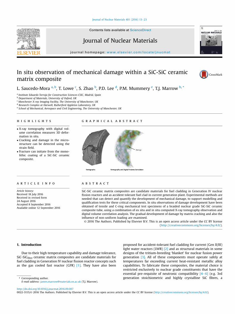
loading stage mounted on a laboratory tomography microscope.The loading stage (Debenwith 20 kN load cell) is described in moredetail in Ref. [17]. The tomographs were obtained using a NikonCustom Bay X-ray Microscope at the Manchester X-ray ImagingFacility; the specimen was mounted with a flexible coupling toallow axial tensile loading (Fig. 1a). Each end of the specimen wasbonded by a cold-setting epoxy resin within a cylindrical hole(depth 10mm, diameter 13 mm), with a free length of 35mm (totalspecimen length 55 mm). This setup permitted medium resolutioncomputed tomography scans with a voxel size of 17 mm at a volu-metric field of view of 34 � 34 � 34 mm. The volume of materialcharacterised was ~960 mm3 and the beam energy was 80 keV.Each tomograph was produced from 3144 radiographs collectedover 180� rotation with a duration of approximately 3 h.
After a reference scan in the unloaded state, the tube samplewas mechanically loaded in tension in displacement control to400 N and scanned again. It was then unloaded to 20 N; scanned;reloaded to 800 N; scanned; unloaded to 20 N; scanned; thenreloaded to 1200 N. An equipment failure (burnt-out filament inthe X ray source) prevented the scan from being completed at1200 N. The peak loads correspond to axial tensile stresses of17.3 MPa, 34.6 MPa and 52.0 MPa. The specimen was then trans-ferred to an Xradia Versa 500 X-ray microscope at the same facility.Tomographs of the tubewall were obtained, at 80 keV X-ray energy,at different heights along the tube axis, each with a volumetric fieldof view of 3.5 � 3.5 � 3.5 mm and a voxel size of 1.7 mm. Thespecimen was not loaded during these observations.
2.2.2. C-ring diametral testA ‘C-ring’ specimen (Fig. 1b) was loaded within the same Uni-
versity of Manchester Deben rig (2 kN load cell) while observedusing synchrotron X-ray computed tomography on the Joint Engi-neering, Environment and Processing (JEEP) beamline I12 at theDiamond Light Source. The specimen width was 4 mm. Compres-sion along the specimen's vertical diameter produced a tensilestrain on the outer surface that was sufficient to cause fracture asthe load was increased under displacement control in steps to~120 N. These synchrotron X-ray tomography observations wereobtained at a voxel size of 3.25 mm and a volumetric field of view of8.3 � 8.3 � 7 mm, with 56 keV X-ray energy. Observations wereobtained under load at each step, and also when unloaded toapproximately 5 N between steps. Each tomograph was produced
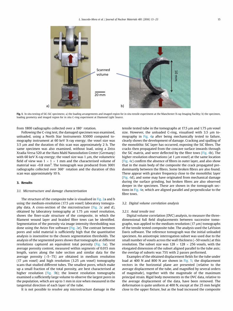
Fig. 1. In situ testing of SiC-SiC specimens; a) the loading arrangements and imaged region for in situ tensile experiment at the Manchester X-ray Imaging Facility; b) the specimen,loading geometry and imaged region for in situ C-ring experiment at Diamond Light Source.
L. Saucedo-Mora et al. / Journal of Nuclear Materials 481 (2016) 13e23 15
from 1800 radiographs collected over a 180� rotation.Following the C-ring test, the damaged specimenwas examined,
unloaded, using a North Star Instruments X5000 computed to-mography instrument at 60 keV X-ray energy; the voxel size was3.5 mm and the duration of this scan was approximately 2 h. Thesame specimen was also examined, without load, using a ZeissXradia Versa 520 at the Hans Mahl Nanosolution Center (Germany)with 60 keV X-ray energy; the voxel size was 1 mm, the volumetricfield of view was 1 � 1 � 1 mm and the characterised volume ofmaterial was ~0.8 mm3. The tomograph was produced from 3001radiographs collected over 360� rotation and the duration of thisscan was approximately 10 h.
3. Results
3.1. Microstructure and damage characterisation
The structure of the composite tube is visualised in Fig. 2a and busing the medium-resolution (17.5 mm voxel) laboratory tomogra-phy data. A cross-section of the microstructure (Fig. 2c and d),obtained by laboratory tomography at 1.75 mm voxel resolution,shows the finer-scale structure of the composite, in which thefilament wound layer and braided fibre tows can be identified.Segmentation of the porosity via image intensity thresholding wasdone using the Avizo Fire software (Fig. 2e). The contrast betweenpores and solid material is sufficiently high that the quantitativeanalysis is insensitive to the chosen segmentation thresholds. Theanalysis of the segmented pores shows that tomographs at differentresolutions captured an equivalent total porosity (Fig. 3a). Theaverage porosity content, measured within segments of 0.015 mmlength, varies along the tube section and similar data for theaverage porosity (~5e7%) are obtained in medium resolution(17 mm voxel) and high resolution (3.25 mm voxel) tomographyscans that studied different tubes. The smallest pores, which makeup a small fraction of the total porosity, are best characterised athigher resolution (Fig. 3b); the lowest resolution tomographsexamined a sufficiently large volume to observe the largest pores inthe population, which are up to 1mm in size whenmeasured in thetangential direction of each layer of the tube.
It is not possible to resolve any microstructure damage in the
tensile tested tube in the tomographs at 17.5 mm and 1.75 mm voxelsize. However, the unloaded C-ring, visualised with 3.5 mm to-mography in Fig. 4a after being mechanically tested to failure,clearly shows the development of damage. Cracking and spalling ofthe monolithic SiC layer has occurred, exposing the SiC fibres. Thecracks then propagated from the concave surface inwards throughthe SiC matrix, and were deflected by the fibre tows (Fig. 4b). Thehigher resolution observations (at 1 mm voxel) at the same location(Fig. 4c) confirm the absence of fibres in outer layer, and also showthat in the main body of the composite the crack propagated pre-dominantly between the fibres. Some broken fibres are also found.These appear with greater frequency close to the monolithic layer(Fig. 4d), and some may have originated from mechanical damageduring the surface grinding, but broken fibres are also observeddeeper in the specimen. These are shown in the tomograph sec-tions in Fig. 4e, which are aligned parallel and perpendicular to thefibre tows.
3.2. Digital volume correlation analysis
3.2.1. Axial tensile testDigital volume correlation (DVC) analysis, to measure the three-
dimensional full field displacements between successive tomo-graphs, was applied to the medium resolution (17 mm) tomographsof the tensile tested composite tube. The analysis used the LaVisionDavis software. The reference tomograph was the initial unloadedspecimen. An anisotropic interrogation subset was used due to thesmall number of voxels across thewall thickness (~50 voxels) at thisresolution. The subset size was 128 � 128 � 256 voxels, with theelongated dimension of the subset aligned parallel to the tube axis;the overlap of subsets was 75% with 2 passes performed.
Examples of the obtained displacement fields for the tube underload at 400 N and 800 N are shown in Fig. 5; the displacementvectors in the horizontal plane are presented (relative to theaverage displacement of the tube, and magnified by several ordersof magnitude), together with the magnitude of the maximumprincipal strain. Rigid body movements in the DVC data, relative tothe average displacement of the data, have been removed. Thedeformation is quite uniform at 400 N, except at the 25 mm heightclose to the upper fixture, but as the load increased the composite

Fig. 2. Visualisation of the SiC-SiC composite tube microstructure; medium-resolution laboratory tomographs (17 mm voxel) as a) surface rendering and b) axial cross-section;compared with c) axial and d) longitudinal cross-sections of a high resolution tomograph (1.7 mm voxel). The porosity, segmented by image intensity thresholding from themedium-resolution tomograph, is shown in e).
Fig. 3. Quantitative analysis of detected porosity in two different specimens examined at different resolutions (i.e. voxel size): a) variation of total porosity with axial position (i.e.height); b) pore populations measured at different voxel resolutions. The 1.7 and 17 mm voxel data are from the same specimen. The representative volume dimensions aredescribed in the text.
L. Saucedo-Mora et al. / Journal of Nuclear Materials 481 (2016) 13e2316
tube begins to deform non-uniformly and this deformation is notrecovered when the load is removed.
Three-dimensional visualisations of the maximum principalstrain, both under load and after unloading, are shown in Fig. 6.These show the progressive development of localised strains thatare distributed non-uniformly throughout the sample. The mag-nitudes of the strains decrease on unloading, but the pattern of
strains remains. There is a greater degree of deformation towardsthe upper end of the tube.
It was not possible to apply extensometers or strain gauges inthe tomography experiments due to the requirements of samplerotation during scans and also the dimensional constraints of theloading rig. However, the displacement fields measured by DVCprovide information that can be used to investigate the tensile
Fig. 4. Post test X-ray tomography observations of C-ring: a) 3D surface rendering, cropped close to the center of the sample to show damage and internal porosity e a crack in themonolithic layer is labelled; b) virtual slice of the X-ray attenuation data at the same position, in the plane of the tube circumference; c) higher resolution slice close to the sameplane; d) tangential slice (1 mm voxel) e the trace of the plane is marked in c); e) radial slices parallel and perpendicular to fibre tows e the traces of the slices are marked in c) andd). Broken fibres are circled in d) and e). The voxel size is 3.5 mm in a) and b) and 1 mm in c) to e).
L. Saucedo-Mora et al. / Journal of Nuclear Materials 481 (2016) 13e23 17
elongation of the tube sample. The relative axial displacementsaround the tensile loaded tube circumference were measured be-tween positions that were separated by a vertical distance of8.2 mm; the location of this gauge length between the approximateheights of z ¼ 7 mm and z ¼ 15 mm is shown in Fig. 6. The esti-mated error in individual displacement magnitude measurementsby DVC is approximately 0.5 voxel (i.e. 8.5 mm). This is based onprevious studies that applied DVC to similar quality tomographs
[18], as it was not possible to obtain a measurement of this due tothe limited number of scans that could be performed in the tensileexperiment. The estimated uncertainty in the average tensile strain,calculated from displacement measurements separated by the8.2 mm gauge length, is 0.15%.
Example data at 800 N are shown in Fig. 7a for the movementsof the top and bottom of the gauge length. The deformation is quitenon-uniform, and is concentrated to one side of the tube. In terms
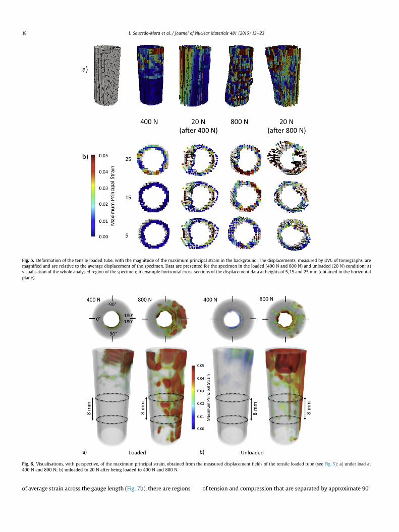
Fig. 5. Deformation of the tensile loaded tube, with the magnitude of the maximum principal strain in the background. The displacements, measured by DVC of tomographs, aremagnified and are relative to the average displacement of the specimen. Data are presented for the specimen in the loaded (400 N and 800 N) and unloaded (20 N) condition: a)visualisation of the whole analysed region of the specimen; b) example horizontal cross-sections of the displacement data at heights of 5, 15 and 25 mm (obtained in the horizontalplane).
Fig. 6. Visualisations, with perspective, of the maximum principal strain, obtained from the measured displacement fields of the tensile loaded tube (see Fig. 5): a) under load at400 N and 800 N; b) unloaded to 20 N after being loaded to 400 N and 800 N.
L. Saucedo-Mora et al. / Journal of Nuclear Materials 481 (2016) 13e2318
of average strain across the gauge length (Fig. 7b), there are regions
of tension and compression that are separated by approximate 90�
Fig. 7. Measurement of the axial displacements and strains from the longitudinal displacement change around the circumference of the tensile loaded tube (see Fig. 6); a) examplevertical displacements at the top and bottom of the 8.2 mm gauge length at 800 N; b) axial strain in the loaded and unloaded states over the same gauge length. The error bars arecalculated from an estimated displacement measurement uncertainty of 0.5 voxel (one voxel is 17 mm).
L. Saucedo-Mora et al. / Journal of Nuclear Materials 481 (2016) 13e23 19
intervals around the circumference. This strain is not fully recov-ered on unloading. This is shown more clearly in Fig. 8, in maps ofthe local axial strains within the selected 8.2 mm gauge lengtharound the circumference of the tube. The magnitude of the localstrains increases with applied load, and the same pattern is main-tained after unloading, indicating localised deformation that is notrecovered.
3.2.2. C-ring diametral testDVC analysis was also applied tomeasure the three-dimensional
full field displacements between the successive high-resolutionsynchrotron X-ray tomographs (at 3.25 mm voxel) of the diametri-cally loaded C-ring specimen. The reference tomograph was theinitial unloaded specimen. The DVC analysis of loaded and unloa-ded tomographs was done with a subset size of 128 � 128 � 128
Fig. 8. 2D visualisations of the axial strain in ~8 mm gauge length region of tensile loaded tuto 400 N and 800 N.
voxels at 50% overlap. An analysis of tomographs between whichthe unloaded specimen was physically translated by 50 mm has astandard deviation of the displacement vector magnitude of 1.2 mm.This was regarded as the measurement uncertainty (i.e. approxi-mately 0.4 voxel), and is typical for DVC of tomographs [18].
In the tested C-ring specimen, a heterogeneous distribution oflocalised strains is observed, which develops progressively inmagnitude and extent with increasing applied load (Fig. 9a).Localised strains remain, with reduced magnitude, after the load isremoved (Fig. 9b). The strains are not uniformly distributed, appearinitially in the upper part of the sample and span the sample width.The strains are superposed on tomography slices of the damagedsample in Fig. 10, which shows that regions of high tensile straincorrespond to observable cracks. These cracks are just visible in thetomographs whilst the specimen is under load (Fig.10a), but cannot
be (see Fig. 6: a) under load at 400 N and 800 N; b) unloaded to 20 N after being loaded
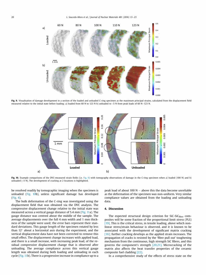
Fig. 9. Visualisation of damage development in a section of the loaded and unloaded C-ring specimen as the maximum principal strains, calculated from the displacement fieldmeasured relative to the initial state before loading; a) loaded from 60 N to 123 N b) unloaded to ~5 N from peak loads of 60 Ne123 N.
Fig. 10. Example comparisons of the DVC-measured strain fields (i.e. Fig. 9) with tomography observations of damage in the C-ring specimen when a) loaded (100 N) and b)unloaded (~5 N). The development of cracking at 2 locations is highlighted.
L. Saucedo-Mora et al. / Journal of Nuclear Materials 481 (2016) 13e2320
be resolved readily by tomographic imaging when the specimen isunloaded (Fig. 10b), unless significant damage has developed(Fig. 4).
The bulk deformation of the C-ring was investigated using thedisplacement field that was obtained via the DVC analysis. Thecompressive displacement change relative to the initial state wasmeasured across a vertical gauge distance of 5.4 mm (Fig. 11a). Thegauge distance was centred about the middle of the sample. Theaverage displacements over the full 4 mm width and 1 mm thick-ness of the sample were used; the error bars represent their stan-dard deviations. This gauge length of the specimen rotated by lessthan 12� about a horizontal axis during the experiment, and thevertical displacement data have not been corrected to remove thissmall effect. The displacement change increases with applied load,and there is a small increase, with increasing peak load, of the re-sidual compressive displacement change that is observed afterunloading. The average compliance across this vertical gaugelength was obtained during both loading and unloading in eachcycle (Fig.11b). There is a progressive increase in compliance up to a
peak load of about 100 N e above this the data become unreliableas the deformation of the specimen was non-uniform. Very similarcompliance values are obtained from the loading and unloadingdata.
4. Discussion
The expected structural design criterion for SiC-SiCfibre com-posites will be some fraction of the proportional limit stress (PLS)[19]. This is the critical stress, in tensile loading, above which non-linear stress/strain behaviour is observed, and it is known to beassociated with the development of significant matrix cracking[16]; further cracking develops as the applied strain increases. Thepropagation of cracks is resisted by the ‘fibre pull out’ tougheningmechanism from the continuous, high strength SiC fibres, and thisgoverns the component's strength [20,21]. Microcracking of thematrix also affects the heat transfer properties of the ceramiccomposite fuel cladding [22].
In a comprehensive study of the effects of stress state on the

Fig. 11. Load-displacement behaviour of the C-ring specimen: a) compressive displacement change measured over a central gauge of 5.4 mm as the applied load was progressivelyincreased in cycles with intermediate unloads; b) the change in compliance with peak load, measured from the displacement change on loading and unloading.
L. Saucedo-Mora et al. / Journal of Nuclear Materials 481 (2016) 13e23 21
strength and stiffness of SiC-SiC ceramic matrix composite tubes[16], acoustic emission and surface observations augmented bydigital image correlation analysis were used to characterise thedevelopment of matrix cracking. The composite was fabricatedfrom layers of filament wound and braided tows of Hi-Nicalon typeS fibres, with a pyrocarbon interphase applied to the fibre preformbefore the SiC matrix was introduced via Chemical Vapour Infil-tration (CVI). Matrix cracking, which saturated rapidly at approxi-mately at a density of 2 mm�1, was associated with acousticemission and the onset of non-linear mechanical behaviour. Intensile loading, this occurred at applied strains above approxi-mately 0.04%.
In situ observations by computed X-ray tomography duringtensile tests of a single tow of a SiC-SiC composite [23] have shownthat the surface observations do not fully characterise damagedevelopment. The material studied was a single tow of 500 Hi-Nicalon type S fibers, coated a pyrocarbon interphase with a CVI-deposited SiC matrix. The tomography observations, obtainedonly when the applied strain above 0.15%, showed that the densityof matrix cracks increased with applied strain and saturated at ahigher density of about 4 mm�1. These major cracks led to fibrefailure, although minor cracking was also observed. Similarbehaviour was observed in computed X-ray tomography observa-tions at 1750 �C [24] of a tensile test of a single tow of 500 Nicolon-Sfibres with a CVI-deposited SiC matrix. Matrix cracking extendeduntil the load was taken fully by the intact fibres. Ex-situ studies oflarger samples fabricated from the same materials that were testedat room temperature developed a saturated matrix crack density of2 mm�1, similar to that observed in other studies, e.g. Ref. [16]. It isthus important to recognise the role the composite meso-scalestructure may have on damage development, as this will affectthe local strains in matrix and fibres in response to the macroscopicapplied strains.
The analysis of the observed porosity (Fig. 3) demonstrates thatcomputed X-ray tomography can provide an effective quantitativeassessment of pores that are sufficiently large; pores need to be atleast an order of magnitude larger than the voxel size to bemeasured reliably. The large pores at the meso-scale provide thebulk of the total porosity, which was between 5 and 7% of the
sample volume. This is lower than detected by Bernachy [16] forsimilarly fabricated composites; the average porosity measured inthree samples using X-ray tomography was reported to be between10.4% and 11.1%, although the voxel resolution in that work is notstated, and characterisation of voids in tomographs can be sensitiveto segmentation methods [25]. The reproducibility at differentresolution of the measurements (Fig. 3) of the larger voids givesconfidence in these data. At a pore size of about 200 mm, there is achange in gradient of the power-law relationship that is observedbetween pore size and number density. This may describe differentpore populations within and between the fibre tows in the braidedstructure. The large pores between the fibre tows are significant todamage development, as observed in Fig. 10, and their size anddistribution may be affected by differences in manufacturing.
Digital volume correlation of tomographs can measure thethree-dimensional deformation behaviour in response to appliedloads, and can also be used to detect cracking as shown by thecomparison of the strain maps and tomographs (Fig. 10). Theobserved strains are due to permanent damage; the opening dis-placements of cracks are visualised as strain, and these relax whenthe load is removed. The measured local strains (e.g. Figs. 6 and 9)are not real strains of the material, but arise from the effect of crackopenings on local gradients between discrete measurements in thedisplacement field. The residual strains indicate that some per-manent deformation has occurred, such that the unloaded cracksdo not fully close. This may be due to the “textile effect” that hasbeen attributed to the reorientation of fibre tows under load indamaged microstructures [16]. It is interesting to note that regionsof tensile strain exist on the inner surface of the C-ring specimenafter unloading (Fig. 10b); this part of the specimen would havebeen under compression during loading and develops an array ofcracks once unloaded, with an average separation of approximately0.5 mm (i.e. ~2 mm�1). The density of cracking is of a similarmagnitude to that reported previously [16,23]. It is also interestingto note the difference in cracking behaviour between the mono-lithic SiC layer and the braided microstructure (Fig. 4). Surfaceobservations of cracking [11,16] might not be fully representative ofsub-surface damage in the composite structure, although it is clearfrom the C-ring test that surface cracks may act as initiation sites

L. Saucedo-Mora et al. / Journal of Nuclear Materials 481 (2016) 13e2322
(Fig. 4).The tensile stress strain behaviour of similar composite tubes
tested by Bernachy [16] exhibited significant non-linearity forapplied tensile stresses above 125 MPa. The onset of non-linearitycorresponded to the onset of significant microcracking damage,which was detected by acoustic emission. The change in compli-ance of the C-ring specimen in this work is also consistent withprogressive accumulation of cracking damage in the specimen(Fig. 4), with negligible inelastic deformation. The elastic modulusis reduced by the presence of multiple cracks. The increase in theresidual displacement in the unloaded state (Fig. 11) may be simplybe due to the high elastic compliance after significant damage hasbeen introduced, as a nominal load of 5 N was applied during theseobservations.
In the tensile loading of the composite tube in this work, theequivalent applied tensile stresses at 400 N and 800 N areapproximately 17.5 MPa and 35 MPa respectively. These are sub-stantially lower than the tensile stress at which significant micro-cracking would be expected, but the localised strains indicate thatcracking damage is developing. The deformation develops non-uniformly at the macro-scale (Fig. 5) and also at the meso-scale(Fig. 7). The measured deformation initially appears quite uni-form at 400 N (Figs. 5a and 8a) except close to the upper fixture. Thefixtures of the jig allowed movement of the specimen to facilitatealignment of the load with its axis (Fig. 1a), but constraint near thefixtures of the specimen may affect the deformation. The magni-tudes of the measured average strains across the selected 8.2 mmgauge length (Fig. 7b) are of the order of those that caused micro-cracking damage in similar composites [16,23]. The precision ofdisplacement measurement by DVC of tomographs at this resolu-tion is not very high, however, and some experimental misalign-ment cannot be ruled out, such that the assumed tensile stressesmay be inaccurate. Hence, the non-uniform pattern of damageobserved in the tensile test is likely to be due to an initialmisalignment of the loading applied to the specimen. The non-uniformity of the measured deformation of the tensile test in-creases as the load increases. This suggests that the development ofdamage affects the compliance and the resulting distribution ofstrain. Spatial variations of the stiffness change the distribution ofstress and the consequent deformation and development of furtherdamage. For instance, at 800 N tensile load, the tensile deformationhas become concentrated on one side of the tube (Fig. 7a). Thebraidedmicrostructuremay also introduce further heterogeneity ofmechanical properties at the meso-scale, which appears in thepatterns of deformation caused by damage (Fig. 7b).
In summary, combined application of digital volume correlationwith in situ X-ray tomography of loaded test specimens provides atool to measure the applied deformation and to detect the locationsof damage, which are shown by high resolution ex-situ observationsto be due to cracking of the SiC matrix. Such observations mightlater be coupled with thermal property measurements e.g. Ref. [22],to better understand the effects of mechanical damage on thethermal performance of ceramics for nuclear fuel clad. In principal,these methods could also be applied under conditions of hightemperature and multi-axial or internal pressure loading that moreclosely simulate the operating or screening test environments.
5. Conclusion
The feasibility has been demonstrated of in situ observation ofdamage development during mechanical testing of the ceramiccomposite component, using a combination of computed X-raytomography and digital volume correlation analysis. The largepores between the fibre tows are significant to damage develop-ment, and computed X-ray tomography can provide an effective
quantitative assessment of these; smaller pores that are not suffi-ciently large relative to the voxel size are not measured reliably.Digital volume correlation of the tomographs can measure thethree-dimensional deformation behaviour in response to appliedloads, detecting cracking and observing residual that may be due toa “textile effect” attributed to the reorientation of fibre tows underload in damaged microstructures.
Acknowledgements
This study was carried out within the UK Engineering andPhysical Sciences Research Council (EPSRC) project ‘‘QUBE: Quasi-Brittle fracture: a 3D Experimentally-validated approach’’ (EP/J019992/1), which supported LS-M and TJM. The support of TJM bythe Oxford Martin School at the University of Oxford is alsogratefully acknowledged. Additional support was also obtained forLS-M from the EPSRC Characterisation of Nanomaterials for EnergyPlatform Grant at Oxford University (EP/K032518/1). Access to theUK Diamond Light Source was provided via Experiment EE10106,and the assistance provided by Dr Christina Reinhard is appreci-ated. We acknowledge funding from the UK EPSRC (EP/J019992/1,EP/K032518, EP/F007906/1, EP/F001452/1, EP/I02249X/1) for theManchester X-ray imaging facility, which was funded in part byEPSRC grants EP/F007906/1, EP/F001452/1 and EP/I02249X/1. Weare grateful to Dr Rosy Manser of Carl Zeiss Ltd and Dr Holger Blankof Carl Zeiss Microscopy GmbH for providing access to the XradiaVersa 520 at the Hans Mahl Nanosolution Center, and to Mr GuyTolley and Mr Julien Noel for access to the X5000 at North StarImaging, Paris. This work contributes to Work Package 3 of theMatISSe Collaborative Project “Materials' Innovations for Safe andSustainable Nuclear” (European Commission Seventh FrameworkProgramme Grant 604862, FP7-Fission-2013), which supplied thematerials and also supported access to the Manchester X-rayImaging Facility. In compliance with RCUK (Research Councils UK)policy, the raw data presented in this paper may be obtained bycontacting the corresponding author.
Appendix A. Supplementary data
Supplementary data related to this article can be found at http://dx.doi.org/10.1016/j.jnucmat.2016.09.007.
References
[1] F. Carre, P. Yvon, P. Anzieu, N. Chauvin, J.-Y. Malo, Update of the French R&Dstrategy on gas-cooled reactors, Nucl. Eng. Des. 240 (2010) 2401e2408, http://dx.doi.org/10.1016/j.nucengdes.2010.02.042.
[2] C. Sauder, A. Michaux, G. Loupias, P. Billaud, J. Braun, Assessment of SiC/SiCcladding for LWRs, in: LWR Fuel Perform. Meet. Top Fuel 2013, AmericanNuclear Society, 2013, pp. 951e956.
[3] Y. Katoh, L.L. Snead, C.H. Henager, A. Hasegawa, A. Kohyama, B. Riccardi, et al.,Current status and critical issues for development of SiC composites for fusionapplications, J. Nucl. Mater. 367e370 (2007) 659e671, http://dx.doi.org/10.1016/j.jnucmat.2007.03.032.
[4] G. Newsome, L.L. Snead, T. Hinoki, Y. Katoh, D. Peters, Evaluation of neutronirradiated silicon carbide and silicon carbide composites, J. Nucl. Mater. 371(2007) 76e89, http://dx.doi.org/10.1016/j.jnucmat.2007.05.007.
[5] T. Nozawa, Y. Katoh, L.L. Snead, The effect of neutron irradiation on the fiber/matrix interphase of silicon carbide composites, Nucl. Mater. 384 (2009)195e211, http://dx.doi.org/10.1016/j.jnucmat.2008.11.015.
[6] Y. Katoh, L.L. Snead, T. Nozawa, S. Kondo, J.T. Busby, Thermophysical andmechanical properties of near-stoichiometric fiber CVI SiC/SiC compositesafter neutron irradiation at elevated temperatures, J. Nucl. Mater. 403 (2010)48e61, http://dx.doi.org/10.1016/j.jnucmat.2010.06.002.
[7] C.P. Deck, G.M. Jacobsen, J. Sheeder, O. Gutierrez, J. Zhang, J. Stone, et al., Char-acterization of SiCeSiC composites for accident tolerant fuel cladding, J. Nucl.Mater. 466 (2015) 667e681, http://dx.doi.org/10.1016/j.jnucmat.2015.08.020.
[8] G.M. Jacobsen, J.D. Stone, H.E. Khalifa, C.P. Deck, C.A. Back, Investigation of theC-ring test for measuring hoop tensile strength of nuclear grade ceramiccomposites, J. Nucl. Mater. 452 (2014) 125e132, http://dx.doi.org/10.1016/j.jnucmat.2014.05.002.

L. Saucedo-Mora et al. / Journal of Nuclear Materials 481 (2016) 13e23 23
[9] D. Zhang, D.R. Hayhurst, Stressestrain and fracture behaviour of 0�/90� andplain weave ceramic matrix composites from tow multi-axial properties, Int. J.Solids Struct. 47 (2010) 2958e2969, http://dx.doi.org/10.1016/j.ijsolstr.2010.06.023.
[10] T. Nozawa, E. Lara-Curzio, Y. Katoh, R.J. Shinavski, Tensile properties ofadvanced SiC/SiC composites for nuclear control rod applications, Ceram. Eng.Sci. Proc. (2008) 223e234.
[11] E. Rohmer, E. Martin, C. Lorrette, Mechanical properties of SiC/SiC braidedtubes for fuel cladding, J. Nucl. Mater 453 (2014) 16e21, http://dx.doi.org/10.1016/j.jnucmat.2014.06.035.
[12] M. Ferraris, M. Salvo, V. Casalegno, Ceramic Integration and Joining Technol-ogies, John Wiley & Sons, Inc., Hoboken, NJ, USA, 2011, http://dx.doi.org/10.1002/9781118056776.
[13] C. Cabet, A. Michaux, C. Fazio, L. Malerba, M.F. Maday, M. Serrano, et al., Thenew EC FP7 MatISSE project: materials' innovations for a safe and sustainablenuclear in Europe, in: SMINS-3, Struct. Mater. Innov. Nucl. Syst. - Work.Proceedings, Idaho Natl. Lab, Idaho Falls, United States, Oct. 2013, 2013, pp.7e10.
[14] L. Saucedo-Mora, T.J. Marrow, Multi-scale damage modelling in a ceramicmatrix composite using a finite-element microstructure meshfree method-ology, Philos. Trans. R. Soc. Lond. A Math. Phys. Eng. Sci. 374 (2016), http://dx.doi.org/10.1098/rsta.2015.0276.
[15] C. Sauder, in: Ceramic Matrix Composites: Nuclear Applications, WileyBlackwell, 2014, pp. 609e646, http://dx.doi.org/10.1002/9781118832998.ch22.
[16] F. Bernachy-Barbe, L. G�el�ebart, M. Bornert, J. Cr�epin, C. Sauder, Anisotropicdamage behavior of SiC/SiC composite tubes: multiaxial testing and damagecharacterization, Compos. Part A Appl. Sci. Manuf. 76 (2015) 281e288, http://dx.doi.org/10.1016/j.compositesa.2015.04.022.
[17] M. Mostafavi, S.A. McDonald, H. Çetinel, P.M. Mummery, T.J. Marrow, Flexuralstrength and defect behaviour of polygranular graphite under different statesof stress, Carbon N. Y. 59 (2013) 325e336, http://dx.doi.org/10.1016/j.carbon.2013.03.025.
[18] Y. Vertyagina, M. Mostafavi, C. Reinhard, R. Atwood, T.J. Marrow, In situquantitative three-dimensional characterisation of sub-indentation crackingin polycrystalline alumina, J. Eur. Ceram. Soc. 34 (2014) 3127e3232, http://dx.doi.org/10.1016/j.jeurceramsoc.2014.04.002.
[19] T. Nozawa, S. Kim, K. Ozawa, H. Tanigawa, Stress envelope of silicon carbidecomposites at elevated temperatures, Fusion Eng. Des. (2014), http://dx.doi.org/10.1016/j.fusengdes.2013.12.032.
[20] N. Lissart, J. Lamon, Damage and failure in ceramic matrix minicomposites:experimental study and model, Acta Mater. 45 (1997) 1025e1044.
[21] J. Lamon, Ceramic Matrix Composites, John Wiley & Sons, Inc., Hoboken, NJ,USA, 2014, http://dx.doi.org/10.1002/9781118832998.
[22] J. El Yagoubi, J. Lamon, J.-C. Batsale, J. Dhote, M. Le Flem, Multiscale thermalcharacterization of mechanically loaded ceramic matrix composite, Exp.Mech. 55 (2015) 783e794, http://dx.doi.org/10.1007/s11340-014-9976-x.
[23] C. Chateau, L. G�el�ebart, M. Bornert, J. Cr�epin, E. Boller, C. Sauder, et al., In situX-ray microtomography characterization of damage in SiCf/SiC mini-composites, Compos. Sci. Technol. 71 (2011) 916e924, http://dx.doi.org/10.1016/j.compscitech.2011.02.008.
[24] H.A. Bale, A. Haboub, A.A. MacDowell, J.R. Nasiatka, D.Y. Parkinson, B.N. Cox, etal., Real-time quantitative imaging of failure events in materials under load attemperatures above 1,600 �C, Nat. Mater 12 (2013) 40e46, http://dx.doi.org/10.1038/nmat3497.
[25] Y. Nikishkov, L. Airoldi, A. Makeev, Measurement of voids in composites by x-ray computed tomography, Compos. Sci. Technol. 89 (2013) 89e97, http://dx.doi.org/10.1016/j.compscitech.2013.09.019.


![Bright Laser-Driven Neutron Source Based on the ... · sensitive material [1], nuclear waste transmutation, and material testing in fission and fusion reactor research [2]. Moreover,](https://img.pdfslide.us/doc/110x75/5f543e49fe743f753c17e188/bright-laser-driven-neutron-source-based-on-the-sensitive-material-1-nuclear.jpg)