Embed Size (px)
Citation preview
July 11, 2009 10:58 WSPC/145-JNOPM 00458
Journal of Nonlinear Optical Physics & MaterialsVol. 18, No. 2 (2009) 167–194c© World Scientific Publishing Company
OPTICAL ANGULAR MANIPULATION OF LIQUIDCRYSTAL DROPLETS IN LASER TWEEZERS
E. BRASSELET∗
Centre de Physique Moleculaire Optique et Hertzienne,Universite Bordeaux 1, CNRS, 351 Cours de la Liberation,
33405 Talence Cedex, France∗[email protected]
S. JUODKAZIS
Research Institute for Electronic Science,Hokkaido University, N21W10 CRIS Bldg.,
Sapporo 001-0021, Japan
Received 8 May 2009
The high sensitivity of liquid crystals to external fields, especially electromagnetic fields,confer to them fascinating properties. In the case of light fields, their large optical non-
linearities over a broad spectrum have great application potential for all-optical devices.The linear optical properties of liquid crystals, such as their high refractive index, bire-fringence and transparency, are also of great practical interest in optofluidics, whichcombines the use of optical tools in microfluidic environments. A representative exampleis the laser micromanipulation of liquid crystalline systems using optical tweezing tech-niques. Liquid crystal droplets represent a class of systems that can be easily preparedand manipulated by light, with or without a nonlinear light-matter coupling. Here wereview different aspects of quasi-statics and dynamical optical angular manipulation ofliquid crystal droplets trapped in laser tweezers. In particular, we discuss to the influ-ence of the phase (nematic, cholesteric or smectic), the bulk ordering symmetry, thedroplet size, the polarization state and power of the trapping light, together with theprominent role of light–matter angular momentum exchanges and optical orientationalnonlinearities.
Keywords: Liquid crystal droplets; laser tweezers; optical orientational nonlinearities;light–matter angular momentum transfer.
1. Introduction
Since the pioneering work of Ashkin almost four decades ago,1 laser tweezers havefound many applications in noncontact easy handling and characterization of matterat the micron scale, as summarized in many reviews on optical tweezing.2–6 Besides
∗Corresponding author.
167
July 11, 2009 10:58 WSPC/145-JNOPM 00458
168 E. Brasselet & S. Juodkazis
the possible optical manipulation in the three dimensions, angular manipulationat a fixed location is another extensively exploited characteristic of laser tweez-ers, that basically involves a coupling between the trapping light field and thetrapped object. This has been originally demonstrated by Friese et al.7 by usingtransparent birefringent calcite microcrystals. In their experiment, the trappedmicrocrystals were realigned and rotated by light owing to spin angular momen-tum (i.e., the angular momentum associated with the polarization state) transfer.This opened the way toward the realization of optically driven micromachines con-trolled by spatiotemporal light beam shaping using holographic optical tweezers,fast electro-optic polarization switching or methods relying on interference pat-terns. Solid state architectures may also be fabricated, but the use of in situ recon-figurable micro-optical elements is desirable, for which liquid crystals (LCs) aregood candidates. The main reasons are the various existing ordered phases (themost common being the nematic, cholesteric and smectic phases8), the high sen-sitivity of their orientational order to external fields (e.g. thermal, mechanical,chemical, electric, magnetic or electromagnetic), and their high birefringence overa very broad range of electromagnetic frequencies. Among the different uses of LCsin laser trapping experiments, one can distinguish the following practical situa-tions, where LCs (i) represent the surrounding medium of a trapped microparticle,(ii) play simultaneously the role of the host fluid and of the trapped object, and(iii) constitute the trapped object itself, which is immersed in an isotropic hostmedium.
The first case corresponds to colloidal particles immersed in LCs — as pro-posed by Poulain et al.9 — where the orientational distortions induced by theparticles are associated with a structural force field. One can mention the experi-ment of Musevic et al.,10 where particles having a refractive index lower than thesurrounding LCs can be trapped and manipulated owing to surface-induced andlaser-induced distortions around the particle. Later, such nonintuitive behaviorshave been demonstrated to be a general feature of laser trapping in anisotropicfluids where polarization of light plays a crucial role.11 The optical tweezing ofsingle microparticles hosted in an anisotropic fluid can also be used for materialstructuration (such as the controlled generation and manipulation of defects12) andcharacterization (such as the measurement of the anisotropic hydrodynamics prop-erties of LCs13 or of the anisotropic force field of a LC colloid itself14).
In the second case, these are the LC defects or structures that are directlymanipulated by light. Demonstrations have been done in nematic,15 smectic16 andcholesteric17,18 mesophases, with application to the determination of in situ materialproperties without the need for a perturbing guest particle as a probe such as theline tension of disclination lines.17 Conversely, light-induced structural deformationscan also be used to manipulate LC localized structures.18
The last case mainly refers LC droplets dispersed in an immiscible host fluid(e.g. water). Then, interfacial tension brings a droplet into almost perfectly spheri-cal shape whose size can be precisely controlled.19,20 LC droplets are easily trapped
July 11, 2009 10:58 WSPC/145-JNOPM 00458
Optical Tweezing of Liquid Crystal Droplets 169
and manipulated by light, due to their high refractive index and birefringence.Actually, reliable light-controlled displacement and/or angular optical manipula-tion have been demonstrated in various mesophases, such as nematic,21–23 smectic24
or cholesteric LCs.13,25 Although the most intuitive way to achieve light-inducedrotation of LC droplets is to operate a spin angular momentum transfer simi-larly to the seminal experiment of Friese et al.,7 light scattering and/or photonabsorption processes may also be considered.23 Importantly, the large optical ori-entational nonlinearities of LCs26,27 can also come into play and enrich much theoptical angular manipulation strategies, as demonstrated experimentally in pureLC droplets25,29,30 and theoretically predicted in the presence of particular pho-toinduced effects.31
The aim of this report is to give an overview of optical angular manipulationof spherical LC droplets. This includes (i) the laser-trapping characteristics (i.e.,the position of the droplet in the trap), (ii) the quasi-statics angular realignment,and (iii) the uniform and nonuniform rotational dynamics, for nematic, smecticand cholesteric phases. Linear elliptical and circularly polarized laser tweezers areconsidered, but we restrict our presentation to nonabsorbing LC droplets (whichcorresponds to almost all studies reported so far). Namely, all the optical effectsunder consideration result from a nonresonant dielectric interaction between lightand LCs. This choice follows the recent work of Manzo et al.,31 who investigatedin detail the influence of dye-dopants (known to resonantly enhance the opticaltorque32,33) on the rotational dynamics of LC droplets. Indeed, Manzo et al. showedthat the observed rigid body rotational motion (i.e., the orientational molecularorder and the rotational fluid flow are locked) is not influenced in practice by thephotoinduced orientational effects associated with the presence of dye moleculeswhereas the role of light absorption by itself is merely to change the trapping beamellipticity threshold value above which rotation is observed.
The plan of this paper is as follows. In Sec. 2, the different kinds of LC dropletsencountered in trapping experiments are presented together with the optical trap-ping standard setup and optical analysis tools. Before we focus on the active opticalangular manipulation of droplets, their position in the optical trap as a functionof their intrinsic structural order is discussed in Sec. 3, which reveals some impor-tant features associated with the elastic nature of LCs, namely light-induced elasticdistortions. Then, the droplet realignment under linearly polarized tweezers is pre-sented in Sec. 4. The transition from statics to rotational dynamics is tackled inSec. 5. Rotational dynamics is detailed in Sec. 6, where various kinds of uniform andnonuniform rotation regimes are discussed. As a matter of fact, the orientationalnonlinearities, whose manifestations are related to droplet symmetry and trappingpolarization, mark out all these aspects of optical angular manipulation. Nonlinearrotational dynamics as a function of the polarization state of the trapping beam isalso discussed. Finally, conclusions are drawn in Sec. 7.
July 11, 2009 10:58 WSPC/145-JNOPM 00458
170 E. Brasselet & S. Juodkazis
2. Laser Trapping of Liquid Crystal Droplets
2.1. The different kinds of usual droplets
LC ordering is described by the local averaged molecular orientation given by aunit vector n called the director. Here, three different LC phases are considered:nematic, cholesteric and smectic, whose description is well documented.8 In short,a nematic phase differs from an isotropic fluid by its structural anisotropy, whichis reflected in all its macroscopic tensorial properties. In the presence of chirality, anematic phase acquires a spontaneous torsion leading to a twisted nematic order,also called cholesteric. Finally, a smectic phase corresponds to a lamellar organiza-tion that depends on the nature of the LC building blocks, which results in manysubcategories of smectic phases.8 Only smectic phase A, where the director is per-pendicular to the lamellar planes, will be considered here due to the very smallnumber of tweezed smectic droplets experiments reported so far.
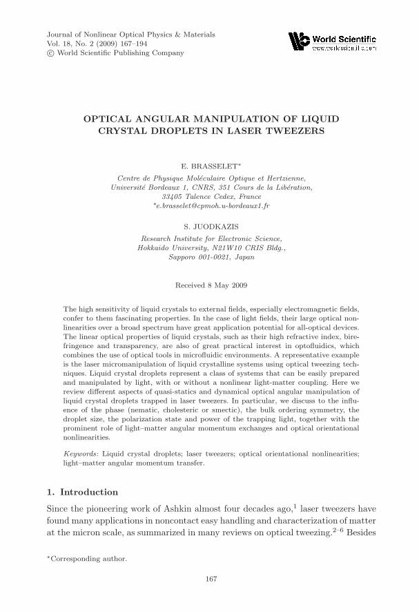
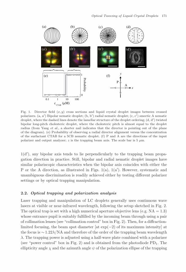
The droplets are prepared by dispersing LCs in water, leading to self-organization into spherical microdroplets whose gross sizes are easily adjusted bymechanical stirring. Various kinds of droplets can be obtained, depending on theLC phase and the boundary conditions at the surface of the droplet. Those dis-cussed here are shown in Fig. 1, where cases (a) and (d) refer to planar boundaryconditions (i.e., the director is parallel to the surface) and cases (b) and (c) referto homeotropic ones (i.e., the director is perpendicular to the surface). For nematicdroplets [see Figs. 1(a) and 1(b)], bipolar or radial bulk ordering is obtained byaddition of an appropriate surfactant. Any anionic (e.g. SDS), cationic (e.g. CTAB)or neutral (e.g. TWEEN20) surfactant can be used to change surface anchoring.This is illustrated in Fig. 1(e), where the probability for a 5CB nematic droplet tohave a radial director alignment versus the concentration of the surfactant CTABis shown.34 In contrast, smectic droplets are found to have a radial structure [seeFig. 1(c)] even without the addition of a surfactant in the surrounding water.24
Finally, the structure of a cholesteric droplet strongly depends on the ratio betweenthe cholesteric pitch (the distance over which the director rotates by a full turn)and the droplet radius, even if the boundary conditions are unchanged.35 Up tonow, the studies on optically trapped cholesteric droplets have considered only lowchirality regimes and planar boundary conditions.13,25 In that case the pitch is ofthe order of, or less than, the droplet radius and a twisted bipolar configuration isadopted, as depicted in Fig. 1(d).
In practice, the symmetry of the director field is revealed by imaging the dropletsbetween two crossed polarizers under white light illumination (see Fig. 2). Typicalimages are shown in the panels (a′)–(d′) of Fig. 1. As expected, the radial nematic(b′) and smectic (c′) droplets possess identical symmetry and give a similar pat-tern whereas bipolar nematic (a′) and twisted bipolar cholesteric (d′) droplets canbe independently identified. Note the remaining degeneracy between the radialnematic/smectic and the bipolar nematic droplets if the bipolar axis is parallel tothe direction of illumination; however, as illustrated in Figs. 1(a), 1(a′) and 1(d),
July 11, 2009 10:58 WSPC/145-JNOPM 00458
Optical Tweezing of Liquid Crystal Droplets 171
AP
(a') (b') (c') (d')
0.1 1 10 100
0
1
Probabilityc
CTAB(µM)
x
y
(a) (b) (c) (d)
(e) (f)
Fig. 1. Director field (x, y) cross sections and liquid crystal droplet images between crossedpolarizers. (a, a′) Bipolar nematic droplet; (b, b′) radial nematic droplet; (c, c′) smectic A nematicdroplet, where the dashed lines denote the lamellar structure of the droplet ordering; (d, d′) twistedbipolar long-pitch cholesteric droplet, where the cholesteric pitch is almost equal to the dropletradius (from Yang et al., a shorter nail indicates that the director is pointing out of the planeof the diagram). (e) Probability of observing a radial director alignment versus the concentrationof the surfactant CTAB for a 5CB nematic droplet. (f) P and A are the directions of the inputpolarizer and output analyzer; z is the trapping beam axis. The scale bar is 5 µm.
1(d′), any bipolar axis tends to lie perpendicularly to the trapping beam propa-gation direction in practice. Still, bipolar and radial nematic droplet images havesimilar polariscopic characteristics when the bipolar axis coincides with either theP or the A direction, as illustrated in Figs. 1(a), 1(a′). However, systematic andunambiguous discrimination is readily achieved either by testing different polarizersettings or by optical trapping manipulation.
2.2. Optical trapping and polarization analysis
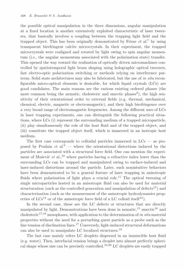
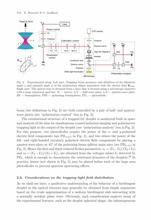
Laser trapping and manipulation of LC droplets generally uses continuous wavelasers at visible or near-infrared wavelength, following the setup sketched in Fig. 2.The optical trap is set with a high numerical aperture objective lens (e.g. NA = 1.3)whose entrance pupil is suitably fulfilled by the incoming beam through using a pairof collimation lenses (see “collimation control” box in Fig. 2). Then, for a diffraction-limited focusing, the beam spot diameter [at exp(−2) of its maximum intensity] atthe focus is ∼ 1.22λ/NA and therefore of the order of the trapping beam wavelengthλ. The trapping power is adjusted using a half-wave plate combined with a polarizer(see “power control” box in Fig. 2) and is obtained from the photodiode PD1. Theellipticity angle χ and the azimuth angle ψ of the polarization ellipse of the trapping
July 11, 2009 10:58 WSPC/145-JNOPM 00458
172 E. Brasselet & S. Juodkazis
lens 1 lens 2
Polarizer
/2
Microscope
Dichroic mirror
High NA Objective
Sample
Analyzer
Condenser lens
Polarizer
White light illumination
CCD camera
Dichroic mirror
/4
Laser
Power control
Polarizationcontrol
Collimation control
Polarization analysis
M
PD1
PD5
PD3
PD2 PD4BS
BS
PBS
PBS
/4
/2
x
Etrap
λ
λ
χ
ψ
λ
λ
Fig. 2. Experimental setup. Left part: Trapping beam geometry and definition of the ellipticityangle χ and azimuth angle ψ of the polarization ellipse associated with the electric field Etrap.Right part: The optical trap is obtained from a laser that is focused using a microscope objectivewith a large numerical aperture. M — mirror; λ/2 — half-wave plate; λ/4 — quarter-wave plate;BS — beamsplitter; PBS — polarizing beamsplitter; PDi — photodiode.
beam (see definitions in Fig. 2) are both controlled by a pair of half- and quarter-wave plates (see “polarization control” box in Fig. 2).
The orientational structure of a trapped LC droplet is monitored both in spaceand analysis of the time by simultaneous crossed polarizes imaging and polarimetrictrapping light at the output of the droplet (see “polarization analysis” box in Fig. 2).For this purpose, two photodiodes acquire the power of the x- and y-polarizedelectric field components (see PDi=2,3 in Fig. 2), and two others the power of theleft- and right-handed circularly polarized electric field components by placing aquarter-wave plate at 45◦ of the polarizing beam splitter main axes (see PDi=4,5 inFig. 2). Hence the first and third reduced Stokes parameters, s1 = (V2−V3)/(V2+V3)and s3 = (V4 −V5)/(V4 +V5), are obtained from the voltages values Vi detected byPDi, which is enough to characterize the rotational dynamics of the droplets.36 Inpractice, lenses (not shown in Fig. 2) may be placed before each of the large areaphotodiodes to prevent spurious aperturing effects.
2.3. Considerations on the trapping light field distribution
As we shall see later, a qualitative understanding of the behavior of a birefringentdroplet in the optical tweezers may generally be obtained from simple argumentsbased on the crude approximation of a uniform birefringent slab interacting witha normally incident plane wave. Obviously, such consideration neglects many ofthe experimental features, such as the droplet spherical shape, the inhomogeneous
July 11, 2009 10:58 WSPC/145-JNOPM 00458
Optical Tweezing of Liquid Crystal Droplets 173
optical axis distribution inside the LC droplet and the tight focusing of light. There-fore, the exact nature of the light field inside the droplet is a priori a complicatedbut necessary step toward quantitative predictions of forces and torques acting onthe LC. Efficient calculation methods have been developed to tackle such prob-lems and expertise has been accumulated from the first developments made byAshkin.37–40 In particular, the T-matrix method has been revealed as an efficienttool43 for studying nontrivial geometries such as possibly absorbing and/or bire-fringent dielectric spheroids. In addition, the case of light beams that possess spinand/or orbital angular momentum, or not, have been explored in much detail.40–42
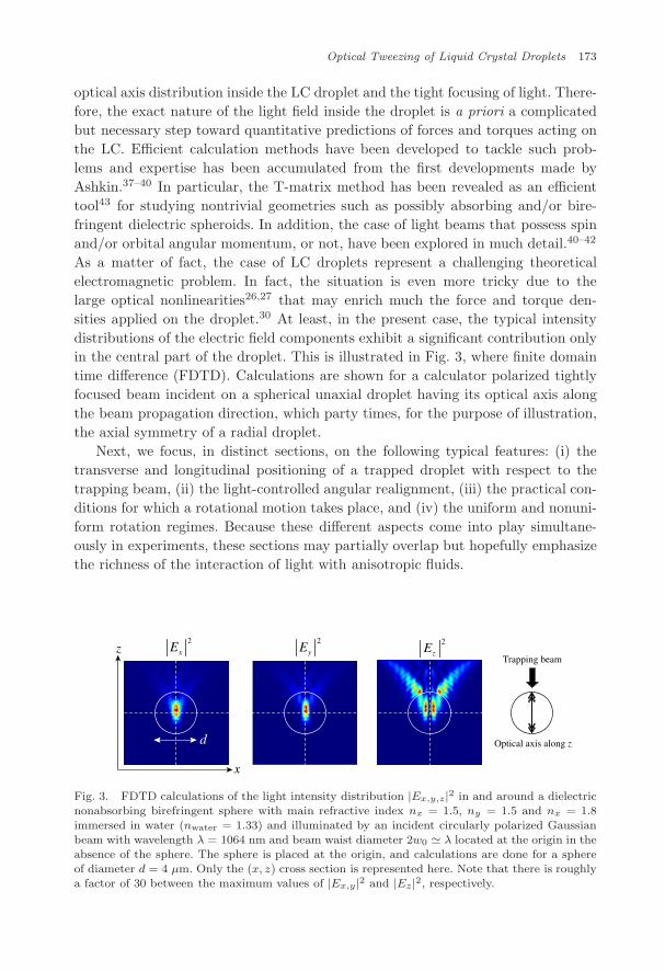
As a matter of fact, the case of LC droplets represent a challenging theoreticalelectromagnetic problem. In fact, the situation is even more tricky due to thelarge optical nonlinearities26,27 that may enrich much the force and torque den-sities applied on the droplet.30 At least, in the present case, the typical intensitydistributions of the electric field components exhibit a significant contribution onlyin the central part of the droplet. This is illustrated in Fig. 3, where finite domaintime difference (FDTD). Calculations are shown for a calculator polarized tightlyfocused beam incident on a spherical unaxial droplet having its optical axis alongthe beam propagation direction, which party times, for the purpose of illustration,the axial symmetry of a radial droplet.
Next, we focus, in distinct sections, on the following typical features: (i) thetransverse and longitudinal positioning of a trapped droplet with respect to thetrapping beam, (ii) the light-controlled angular realignment, (iii) the practical con-ditions for which a rotational motion takes place, and (iv) the uniform and nonuni-form rotation regimes. Because these different aspects come into play simultane-ously in experiments, these sections may partially overlap but hopefully emphasizethe richness of the interaction of light with anisotropic fluids.
z
x
2
xE2
yE2
zE
d Optical axis along z
Trapping beam
Fig. 3. FDTD calculations of the light intensity distribution |Ex,y,z|2 in and around a dielectricnonabsorbing birefringent sphere with main refractive index nx = 1.5, ny = 1.5 and nx = 1.8immersed in water (nwater = 1.33) and illuminated by an incident circularly polarized Gaussianbeam with wavelength λ = 1064 nm and beam waist diameter 2w0 � λ located at the origin in theabsence of the sphere. The sphere is placed at the origin, and calculations are done for a sphereof diameter d = 4 µm. Only the (x, z) cross section is represented here. Note that there is roughlya factor of 30 between the maximum values of |Ex,y|2 and |Ez|2, respectively.
July 11, 2009 10:58 WSPC/145-JNOPM 00458
174 E. Brasselet & S. Juodkazis
3. Off-Axis and Axial Positioning of a Droplet in Tweezers
It is well known that the trapping location of a spherical dielectric particle is notcentered on the maximum intensity of the unperturbed incident Gaussian trappingbeam, but axially displaced. This originates from refraction effects that change thehot spots’ location.40 In the case of LC droplets, a repositioning is also expectedbut transverse and longitudinal effects occur either separately or simultaneously,depending on the LC droplet phase and symmetry.
3.1. Nematic droplets
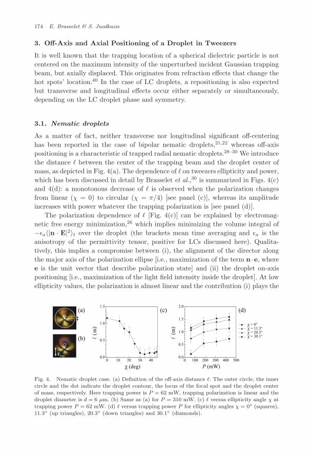
As a matter of fact, neither transverse nor longitudinal significant off-centeringhas been reported in the case of bipolar nematic droplets,21,22 whereas off-axispositioning is a characteristic of trapped radial nematic droplets.28–30 We introducethe distance � between the center of the trapping beam and the droplet center ofmass, as depicted in Fig. 4(a). The dependence of � on tweezers ellipticity and power,which has been discussed in detail by Brasselet et al.,30 is summarized in Figs. 4(c)and 4(d): a monotonous decrease of � is observed when the polarization changesfrom linear (χ = 0) to circular (χ = π/4) [see panel (c)], whereas its amplitudeincreases with power whatever the trapping polarization is [see panel (d)].
The polarization dependence of � [Fig. 4(c)] can be explained by electromag-netic free energy minimization,26 which implies minimizing the volume integral of−εa〈|n · E|2〉t over the droplet (the brackets mean time averaging and εa is theanisotropy of the permittivity tensor, positive for LCs discussed here). Qualita-tively, this implies a compromise between (i), the alignment of the director alongthe major axis of the polarization ellipse [i.e., maximization of the term n ·e, wheree is the unit vector that describe polarization state] and (ii) the droplet on-axispositioning [i.e., maximization of the light field intensity inside the droplet]. At lowellipticity values, the polarization is almost linear and the contribution (i) plays the
0 100 200 300 400 500
χ = 0°χ = 11.3°χ = 20.3°χ = 30.1°
0.0
0.5
1.0
1.5
2.0
(m
)
P (mW)0 10 20 30 40
0.0
0.5
1.0
1.5
(m
)
(deg)χ
(c) (d)
Etrap
(a)
(b)
Fig. 4. Nematic droplet case. (a) Definition of the off-axis distance �. The outer circle, the innercircle and the dot indicate the droplet contour, the locus of the focal spot and the droplet centerof mass, respectively. Here trapping power is P = 62 mW, trapping polarization is linear and thedroplet diameter is d = 6 µm. (b) Same as (a) for P = 310 mW. (c) � versus ellipticity angle χ at
trapping power P = 62 mW. (d) � versus trapping power P for ellipticity angles χ = 0◦ (squares),11.3◦ (up triangles), 20.3◦ (down triangles) and 30.1◦ (diamonds).
July 11, 2009 10:58 WSPC/145-JNOPM 00458
Optical Tweezing of Liquid Crystal Droplets 175
dominant role, thus leading to a nonzero value of �, whereas at large ellipticity val-ues the polarization is almost circular and the contribution (ii) becomes prominent,which implies that � → 0. Moreover, the power dependence [Fig. 4(d)] evidences anonlinear effect associated with optical reordering, as shown in Fig. 4(b) for linearpolarization and high trapping power. In that case, the free elastic energy associatedwith elastic deformations26 has also to be taken into account.
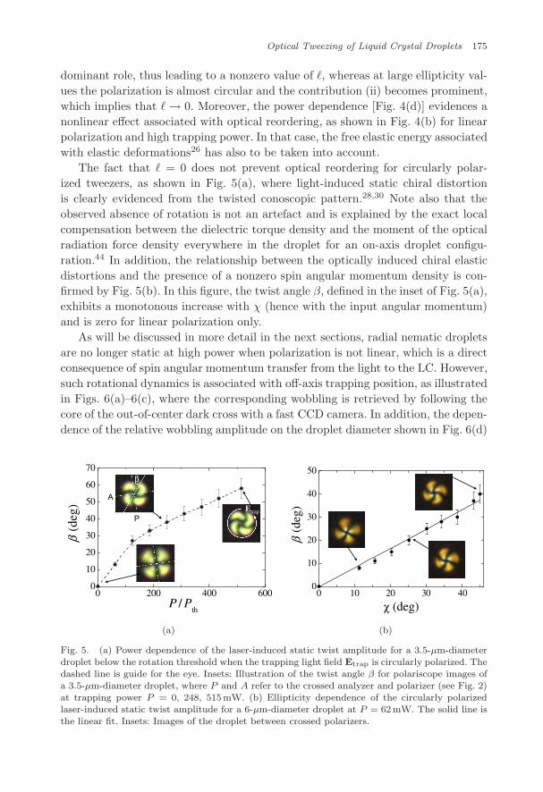
The fact that � = 0 does not prevent optical reordering for circularly polar-ized tweezers, as shown in Fig. 5(a), where light-induced static chiral distortionis clearly evidenced from the twisted conoscopic pattern.28,30 Note also that theobserved absence of rotation is not an artefact and is explained by the exact localcompensation between the dielectric torque density and the moment of the opticalradiation force density everywhere in the droplet for an on-axis droplet configu-ration.44 In addition, the relationship between the optically induced chiral elasticdistortions and the presence of a nonzero spin angular momentum density is con-firmed by Fig. 5(b). In this figure, the twist angle β, defined in the inset of Fig. 5(a),exhibits a monotonous increase with χ (hence with the input angular momentum)and is zero for linear polarization only.
As will be discussed in more detail in the next sections, radial nematic dropletsare no longer static at high power when polarization is not linear, which is a directconsequence of spin angular momentum transfer from the light to the LC. However,such rotational dynamics is associated with off-axis trapping position, as illustratedin Figs. 6(a)–6(c), where the corresponding wobbling is retrieved by following thecore of the out-of-center dark cross with a fast CCD camera. In addition, the depen-dence of the relative wobbling amplitude on the droplet diameter shown in Fig. 6(d)
Etrap
0 200 400 6000
10
20
30
40
50
60
70
β(d
eg)
P / Pth
A
P
β
β(d
eg)
0 10 20 3 4000
10
20
30
40
50
χ (deg)
(a) (b)
Fig. 5. (a) Power dependence of the laser-induced static twist amplitude for a 3.5-µm-diameterdroplet below the rotation threshold when the trapping light field Etrap is circularly polarized. Thedashed line is guide for the eye. Insets: Illustration of the twist angle β for polariscope images ofa 3.5-µm-diameter droplet, where P and A refer to the crossed analyzer and polarizer (see Fig. 2)at trapping power P = 0, 248, 515mW. (b) Ellipticity dependence of the circularly polarizedlaser-induced static twist amplitude for a 6-µm-diameter droplet at P = 62mW. The solid line isthe linear fit. Insets: Images of the droplet between crossed polarizers.
July 11, 2009 10:58 WSPC/145-JNOPM 00458
176 E. Brasselet & S. Juodkazis
5 6 7 8 9 100.20
0.25
0.30
0.35
0.40
0.45
2 /
d
d (µm)
t
(a) (b) (c) (d)2
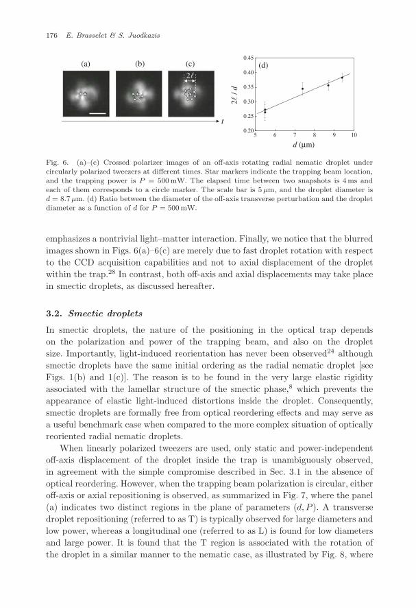
Fig. 6. (a)–(c) Crossed polarizer images of an off-axis rotating radial nematic droplet undercircularly polarized tweezers at different times. Star markers indicate the trapping beam location,and the trapping power is P = 500 mW. The elapsed time between two snapshots is 4ms andeach of them corresponds to a circle marker. The scale bar is 5µm, and the droplet diameter isd = 8.7µm. (d) Ratio between the diameter of the off-axis transverse perturbation and the dropletdiameter as a function of d for P = 500 mW.
emphasizes a nontrivial light–matter interaction. Finally, we notice that the blurredimages shown in Figs. 6(a)–6(c) are merely due to fast droplet rotation with respectto the CCD acquisition capabilities and not to axial displacement of the dropletwithin the trap.28 In contrast, both off-axis and axial displacements may take placein smectic droplets, as discussed hereafter.
3.2. Smectic droplets
In smectic droplets, the nature of the positioning in the optical trap dependson the polarization and power of the trapping beam, and also on the dropletsize. Importantly, light-induced reorientation has never been observed24 althoughsmectic droplets have the same initial ordering as the radial nematic droplet [seeFigs. 1(b) and 1(c)]. The reason is to be found in the very large elastic rigidityassociated with the lamellar structure of the smectic phase,8 which prevents theappearance of elastic light-induced distortions inside the droplet. Consequently,smectic droplets are formally free from optical reordering effects and may serve asa useful benchmark case when compared to the more complex situation of opticallyreoriented radial nematic droplets.
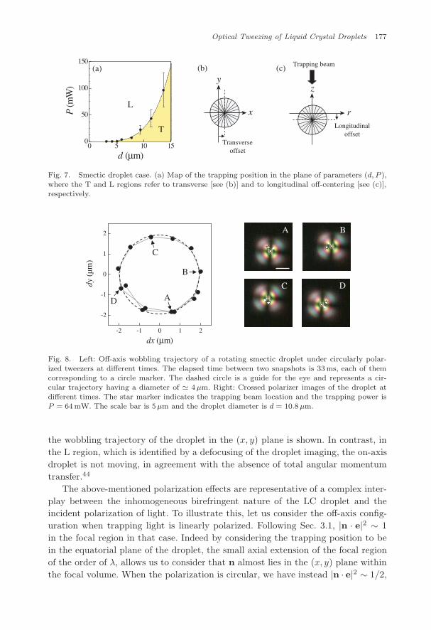
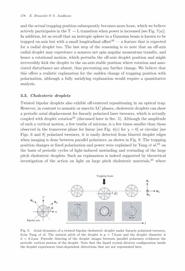
When linearly polarized tweezers are used, only static and power-independentoff-axis displacement of the droplet inside the trap is unambiguously observed,in agreement with the simple compromise described in Sec. 3.1 in the absence ofoptical reordering. However, when the trapping beam polarization is circular, eitheroff-axis or axial repositioning is observed, as summarized in Fig. 7, where the panel(a) indicates two distinct regions in the plane of parameters (d, P ). A transversedroplet repositioning (referred to as T) is typically observed for large diameters andlow power, whereas a longitudinal one (referred to as L) is found for low diametersand large power. It is found that the T region is associated with the rotation ofthe droplet in a similar manner to the nematic case, as illustrated by Fig. 8, where
July 11, 2009 10:58 WSPC/145-JNOPM 00458
Optical Tweezing of Liquid Crystal Droplets 177
0 5 10 150
50
100
150P
(mW
)
d (µm)
x
y
Transverseoffset
r
z
Longitudinaloffset
(a) (b) (c)
L
T
Trapping beam
Fig. 7. Smectic droplet case. (a) Map of the trapping position in the plane of parameters (d, P ),where the T and L regions refer to transverse [see (b)] and to longitudinal off-centering [see (c)],respectively.
-2 -1 0 1 2
-2
-1
0
1
2
dy (
µm)
dx (µm)
A
B
B
C D
A
C
D
Fig. 8. Left: Off-axis wobbling trajectory of a rotating smectic droplet under circularly polar-ized tweezers at different times. The elapsed time between two snapshots is 33 ms, each of themcorresponding to a circle marker. The dashed circle is a guide for the eye and represents a cir-cular trajectory having a diameter of � 4µm. Right: Crossed polarizer images of the droplet atdifferent times. The star marker indicates the trapping beam location and the trapping power isP = 64 mW. The scale bar is 5µm and the droplet diameter is d = 10.8µm.
the wobbling trajectory of the droplet in the (x, y) plane is shown. In contrast, inthe L region, which is identified by a defocusing of the droplet imaging, the on-axisdroplet is not moving, in agreement with the absence of total angular momentumtransfer.44
The above-mentioned polarization effects are representative of a complex inter-play between the inhomogeneous birefringent nature of the LC droplet and theincident polarization of light. To illustrate this, let us consider the off-axis config-uration when trapping light is linearly polarized. Following Sec. 3.1, |n · e|2 ∼ 1in the focal region in that case. Indeed by considering the trapping position to bein the equatorial plane of the droplet, the small axial extension of the focal regionof the order of λ, allows us to consider that n almost lies in the (x, y) plane withinthe focal volume. When the polarization is circular, we have instead |n · e|2 ∼ 1/2,
July 11, 2009 10:58 WSPC/145-JNOPM 00458
178 E. Brasselet & S. Juodkazis
and the actual trapping position subsequently becomes more loose, which we believeactively participates in the T → L transition when power is increased [see Fig. 7(a)].In addition, let us recall that an isotropic sphere in a Gaussian beam is known to betrapped on-axis but with a small longitudinal offset40 — a feature that is expectedfor a radial droplet too. The last step of the reasoning is to note that an off-axisradial droplet may experience a nonzero net spin angular momentum transfer, andhence a rotational motion, which perturbs the off-axis droplet position and mightirreversibly kick the droplet to the on-axis stable position where rotation and asso-ciated disturbance are absent, thus preventing any further change. We believe thatthis offers a realistic explanation for the sudden change of trapping position withpolarization, although a fully satisfying explanation would require a quantitativeanalysis.
3.3. Cholesteric droplets
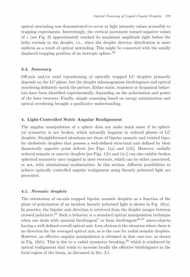
Twisted bipolar droplets also exhibit off-centered repositioning in an optical trap.However, in contrast to nematic or smectic LC phases, cholesteric droplets can showa periodic axial displacement for linearly polarized laser tweezers, which is actuallycoupled with droplet rotation25 (discussed later in Sec. 5). Although the amplitudeof such a vertical motion, a few tenths of microns, is a few times smaller than thoseobserved in the transverse plane for linear [see Fig. 4(c) for χ = 0] or circular [seeFigs. 6 and 8] polarized tweezers, it is easily detected from blurred droplet edgeswhen imaging is done between parallel polarizers, as shown in Fig. 9. The trappingposition changes at fixed polarization and power were explained by Yang et al.25 onthe basis of periodic cycles of light-induced unwinding and rewinding of the largepitch cholesteric droplets. Such an explanation is indeed supported by theoreticalinvestigation of the action on light on large pitch cholesteric materials,45 where
xθ
Bipolar axis
y
t
θφ uu
uθ
φu
zu
dz
Trapping beam
Fig. 9. Axial dynamics of a twisted bipolar cholesteric droplet under linearly polarized tweezers,from Yang et al. The natural pitch of the droplet is p = 7.8µm and the droplet diameter isd = 8.2µm. Periodic blurring of the droplet images between parallel polarizers evidences theperiodic vertical motion of the droplet. Note that the liquid crystal director configuration insidethe droplet experiences time-dependent distortions that are not represented here.
July 11, 2009 10:58 WSPC/145-JNOPM 00458
Optical Tweezing of Liquid Crystal Droplets 179
optical unwinding was demonstrated to occur at light intensity values accessible totrapping experiments. Interestingly, the vertical movement toward negative valuesof z (see Fig. 9) approximately reached its maximum amplitude right before thehelix rewinds in the droplet, i.e., when the droplet director distribution is moreuniform as a result of optical unwinding. This might be connected with the axiallydisplaced trapping position of an isotropic sphere.40
3.4. Summary
Off-axis and/or axial repositioning of optically trapped LC droplets primarilydepends on the LC phase, but the droplet inhomogeneous birefringence and opticalreordering definitely enrich the picture. Either static, transient or dynamical behav-iors have been identified experimentally, depending on the polarization and powerof the laser tweezers. Finally, simple reasoning based on energy minimization andoptical reordering brought a qualitative understanding.
4. Light-Controlled Static Angular Realignment
The angular manipulation of a sphere does not make much sense if its spheri-cal symmetry is not broken, which naturally happens in ordered phases of LCdroplets. Straightforward situations are those of bipolar nematic and twisted bipo-lar cholesteric droplets that possess a well-defined structural axis defined by theirdiametrally opposite point defects [see Figs. 1(a) and 1(d)]. However, radiallyordered nematic or smectic droplets [see Figs. 1(b) and 1(c)] can also exhibit brokenspherical symmetry once trapped in laser tweezers, which can be either associated,or not, with orientational nonlinearities. In this section, different possibilities toachieve optically controlled angular realignment using linearly polarized light arepresented.
4.1. Nematic droplets
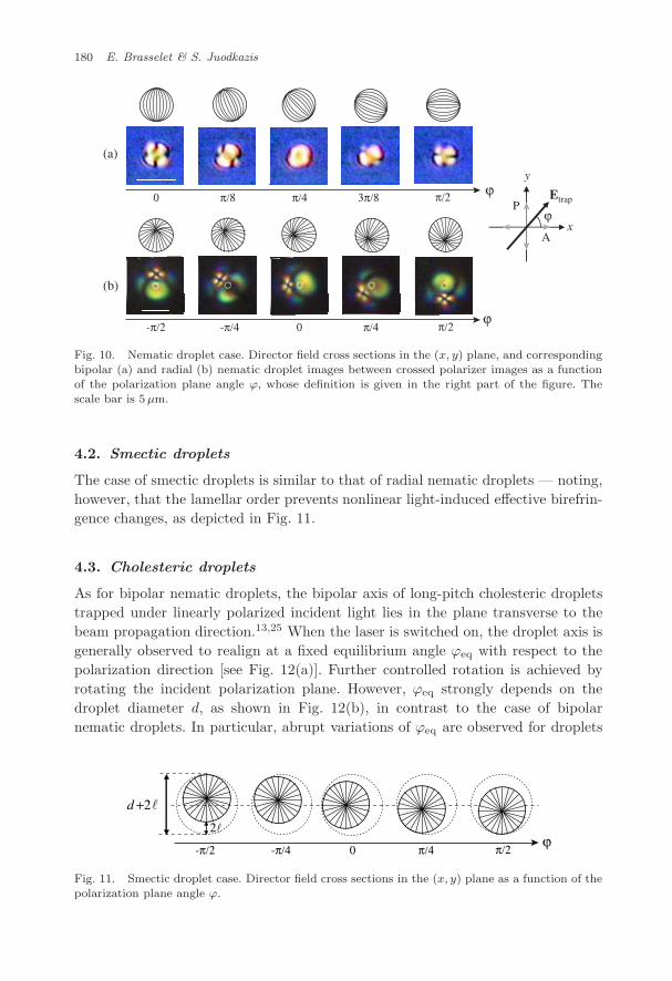
The orientation of on-axis trapped bipolar nematic droplets as a function of theplane of polarization of an incident linearly polarized light is shown in Fig. 10(a).In practice, the bipolar axis direction is retrieved from the droplet images betweencrossed polarizers.21 Such a behavior is a standard optical manipulation techniquewhen one deals with uniaxial birefringent7 or form birefringent46,47 micro-objectshaving a well-defined overall optical axis. Less obvious is the situation where there isno direction for the averaged optical axis, as is the case for radial nematic droplets.However, an effective angular manipulation is obtained in that case too, as shownin Fig. 10(b). This is due to a radial symmetry breaking,30 which is reinforced byoptical realignment that tends to increase locally the effective birefringence in thefocal region of the beam, as discussed in Sec. 3.1.
July 11, 2009 10:58 WSPC/145-JNOPM 00458
180 E. Brasselet & S. Juodkazis
A
P
x
y
Etrap
ϕ0 π/8 π/4 3π/8 π/2
-π/2 -π/4 0 π/4 π/2
(a)
(b)
ϕ
ϕ
Fig. 10. Nematic droplet case. Director field cross sections in the (x, y) plane, and correspondingbipolar (a) and radial (b) nematic droplet images between crossed polarizer images as a functionof the polarization plane angle ϕ, whose definition is given in the right part of the figure. Thescale bar is 5µm.
4.2. Smectic droplets
The case of smectic droplets is similar to that of radial nematic droplets — noting,however, that the lamellar order prevents nonlinear light-induced effective birefrin-gence changes, as depicted in Fig. 11.
4.3. Cholesteric droplets
As for bipolar nematic droplets, the bipolar axis of long-pitch cholesteric dropletstrapped under linearly polarized incident light lies in the plane transverse to thebeam propagation direction.13,25 When the laser is switched on, the droplet axis isgenerally observed to realign at a fixed equilibrium angle ϕeq with respect to thepolarization direction [see Fig. 12(a)]. Further controlled rotation is achieved byrotating the incident polarization plane. However, ϕeq strongly depends on thedroplet diameter d, as shown in Fig. 12(b), in contrast to the case of bipolarnematic droplets. In particular, abrupt variations of ϕeq are observed for droplets
-π/2 -π/4 0 π/4 π/2
2�
� +2d
ϕ
Fig. 11. Smectic droplet case. Director field cross sections in the (x, y) plane as a function of thepolarization plane angle ϕ.
July 11, 2009 10:58 WSPC/145-JNOPM 00458
Optical Tweezing of Liquid Crystal Droplets 181
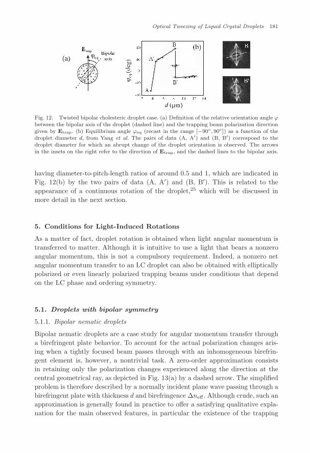
Fig. 12. Twisted bipolar cholesteric droplet case. (a) Definition of the relative orientation angle ϕbetween the bipolar axis of the droplet (dashed line) and the trapping beam polarization directiongiven by Etrap. (b) Equilibrium angle ϕeq (recast in the range [−90◦, 90◦]) as a function of thedroplet diameter d, from Yang et al. The pairs of data (A, A′) and (B, B′) correspond to thedroplet diameter for which an abrupt change of the droplet orientation is observed. The arrowsin the insets on the right refer to the direction of Etrap, and the dashed lines to the bipolar axis.
having diameter-to-pitch-length ratios of around 0.5 and 1, which are indicated inFig. 12(b) by the two pairs of data (A, A′) and (B, B′). This is related to theappearance of a continuous rotation of the droplet,25 which will be discussed inmore detail in the next section.
5. Conditions for Light-Induced Rotations
As a matter of fact, droplet rotation is obtained when light angular momentum istransferred to matter. Although it is intuitive to use a light that bears a nonzeroangular momentum, this is not a compulsory requirement. Indeed, a nonzero netangular momentum transfer to an LC droplet can also be obtained with ellipticallypolarized or even linearly polarized trapping beams under conditions that dependon the LC phase and ordering symmetry.
5.1. Droplets with bipolar symmetry
5.1.1. Bipolar nematic droplets
Bipolar nematic droplets are a case study for angular momentum transfer througha birefringent plate behavior. To account for the actual polarization changes aris-ing when a tightly focused beam passes through with an inhomogeneous birefrin-gent element is, however, a nontrivial task. A zero-order approximation consistsin retaining only the polarization changes experienced along the direction at thecentral geometrical ray, as depicted in Fig. 13(a) by a dashed arrow. The simplifiedproblem is therefore described by a normally incident plane wave passing through abirefringent plate with thickness d and birefringence ∆neff . Although crude, such anapproximation is generally found in practice to offer a satisfying qualitative expla-nation for the main observed features, in particular the existence of the trapping
July 11, 2009 10:58 WSPC/145-JNOPM 00458
182 E. Brasselet & S. Juodkazis
x
z
Trapping beamEtrap
Etrap
ϕeq
χ =χrot0 π /4
Etrap
χ
(a) (b)
x
y Opticalaxis
d
0/ =dtdϕ 0/ ≠dtdϕ
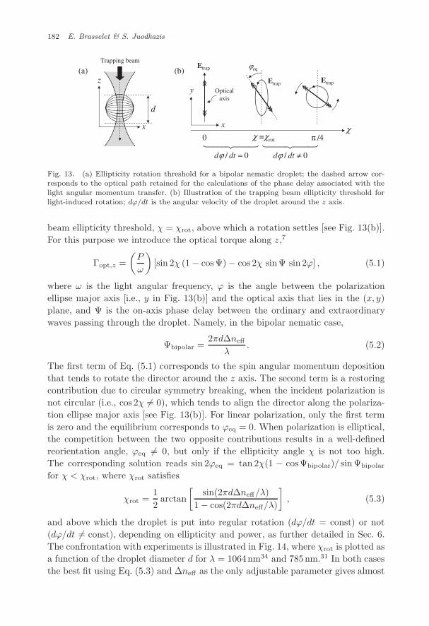
Fig. 13. (a) Ellipticity rotation threshold for a bipolar nematic droplet; the dashed arrow cor-responds to the optical path retained for the calculations of the phase delay associated with thelight angular momentum transfer. (b) Illustration of the trapping beam ellipticity threshold forlight-induced rotation; dϕ/dt is the angular velocity of the droplet around the z axis.
beam ellipticity threshold, χ = χrot, above which a rotation settles [see Fig. 13(b)].For this purpose we introduce the optical torque along z,7
Γopt,z =(P
ω
)[sin 2χ (1 − cosΨ) − cos 2χ sinΨ sin 2ϕ] , (5.1)
where ω is the light angular frequency, ϕ is the angle between the polarizationellipse major axis [i.e., y in Fig. 13(b)] and the optical axis that lies in the (x, y)plane, and Ψ is the on-axis phase delay between the ordinary and extraordinarywaves passing through the droplet. Namely, in the bipolar nematic case,
Ψbipolar =2πd∆neff
λ. (5.2)
The first term of Eq. (5.1) corresponds to the spin angular momentum depositionthat tends to rotate the director around the z axis. The second term is a restoringcontribution due to circular symmetry breaking, when the incident polarization isnot circular (i.e., cos 2χ �= 0), which tends to align the director along the polariza-tion ellipse major axis [see Fig. 13(b)]. For linear polarization, only the first termis zero and the equilibrium corresponds to ϕeq = 0. When polarization is elliptical,the competition between the two opposite contributions results in a well-definedreorientation angle, ϕeq �= 0, but only if the ellipticity angle χ is not too high.The corresponding solution reads sin 2ϕeq = tan 2χ(1 − cosΨbipolar)/ sin Ψbipolar
for χ < χrot, where χrot satisfies
χrot =12
arctan[
sin(2πd∆neff/λ)1 − cos(2πd∆neff/λ)
], (5.3)
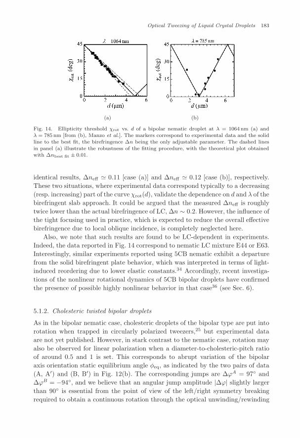
and above which the droplet is put into regular rotation (dϕ/dt = const) or not(dϕ/dt �= const), depending on ellipticity and power, as further detailed in Sec. 6.The confrontation with experiments is illustrated in Fig. 14, where χrot is plotted asa function of the droplet diameter d for λ = 1064nm34 and 785nm.31 In both casesthe best fit using Eq. (5.3) and ∆neff as the only adjustable parameter gives almost
July 11, 2009 10:58 WSPC/145-JNOPM 00458
Optical Tweezing of Liquid Crystal Droplets 183
(a) (b)
Fig. 14. Ellipticity threshold χrot vs. d of a bipolar nematic droplet at λ = 1064 nm (a) andλ = 785 nm [from (b), Manzo et al.]. The markers correspond to experimental data and the solidline to the best fit, the birefringence ∆n being the only adjustable parameter. The dashed linesin panel (a) illustrate the robustness of the fitting procedure, with the theoretical plot obtainedwith ∆nbest fit ± 0.01.
identical results, ∆neff � 0.11 [case (a)] and ∆neff � 0.12 [case (b)], respectively.These two situations, where experimental data correspond typically to a decreasing(resp. increasing) part of the curve χrot(d), validate the dependence on d and λ of thebirefringent slab approach. It could be argued that the measured ∆neff is roughlytwice lower than the actual birefringence of LC, ∆n ∼ 0.2. However, the influence ofthe tight focusing used in practice, which is expected to reduce the overall effectivebirefringence due to local oblique incidence, is completely neglected here.
Also, we note that such results are found to be LC-dependent in experiments.Indeed, the data reported in Fig. 14 correspond to nematic LC mixture E44 or E63.Interestingly, similar experiments reported using 5CB nematic exhibit a departurefrom the solid birefringent plate behavior, which was interpreted in terms of light-induced reordering due to lower elastic constants.34 Accordingly, recent investiga-tions of the nonlinear rotational dynamics of 5CB bipolar droplets have confirmedthe presence of possible highly nonlinear behavior in that case36 (see Sec. 6).
5.1.2. Cholesteric twisted bipolar droplets
As in the bipolar nematic case, cholesteric droplets of the bipolar type are put intorotation when trapped in circularly polarized tweezers,25 but experimental dataare not yet published. However, in stark contrast to the nematic case, rotation mayalso be observed for linear polarization when a diameter-to-cholesteric-pitch ratioof around 0.5 and 1 is set. This corresponds to abrupt variation of the bipolaraxis orientation static equilibrium angle φeq, as indicated by the two pairs of data(A, A′) and (B, B′) in Fig. 12(b). The corresponding jumps are ∆ϕA = 97◦ and∆ϕB = −94◦, and we believe that an angular jump amplitude |∆ϕ| slightly largerthan 90◦ is essential from the point of view of the left/right symmetry breakingrequired to obtain a continuous rotation through the optical unwinding/rewinding
July 11, 2009 10:58 WSPC/145-JNOPM 00458
184 E. Brasselet & S. Juodkazis
process proposed by Yang et al.25 Note that the handedness of the rotation remainsan open question. As a matter of fact, since the rotation is due to the presence ofchirality, its handedness is likely controlled by the handedness of the chiral dopant,which is to be confirmed experimentally. In addition, it would be interesting todemonstrate whether the sign of ∆ϕ does control the sense of rotation, which islikely too.
5.2. Droplets with radial symmetry
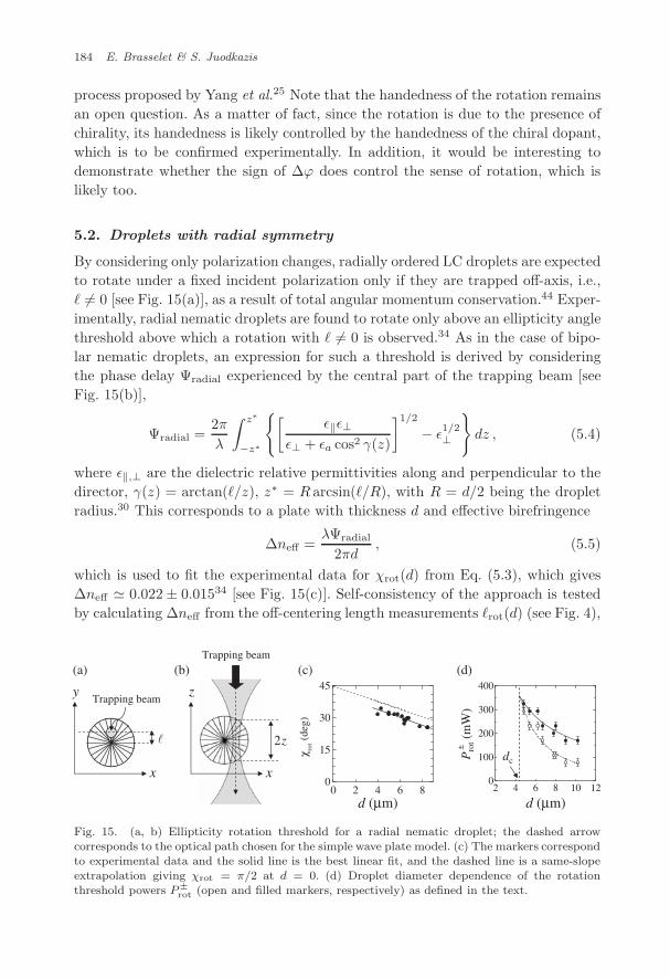
By considering only polarization changes, radially ordered LC droplets are expectedto rotate under a fixed incident polarization only if they are trapped off-axis, i.e.,� �= 0 [see Fig. 15(a)], as a result of total angular momentum conservation.44 Exper-imentally, radial nematic droplets are found to rotate only above an ellipticity anglethreshold above which a rotation with � �= 0 is observed.34 As in the case of bipo-lar nematic droplets, an expression for such a threshold is derived by consideringthe phase delay Ψradial experienced by the central part of the trapping beam [seeFig. 15(b)],
Ψradial =2πλ
∫ z∗
−z∗
{[ε‖ε⊥
ε⊥ + εa cos2 γ(z)
]1/2
− ε1/2⊥
}dz , (5.4)
where ε‖,⊥ are the dielectric relative permittivities along and perpendicular to thedirector, γ(z) = arctan(�/z), z∗ = R arcsin(�/R), with R = d/2 being the dropletradius.30 This corresponds to a plate with thickness d and effective birefringence
∆neff =λΨradial
2πd, (5.5)
which is used to fit the experimental data for χrot(d) from Eq. (5.3), which gives∆neff � 0.022 ± 0.01534 [see Fig. 15(c)]. Self-consistency of the approach is testedby calculating ∆neff from the off-centering length measurements �rot(d) (see Fig. 4),
x
yTrapping beam
x
z
Trapping beam
0 2 4 6 80
15
30
45
rot(d
eg)
χ
z2
2 4 6 8 10 120
100
200
300
400
d (µm)d (µm)
Pro
t(m
W)
±
dc
(a) (b) (c) (d)
Fig. 15. (a, b) Ellipticity rotation threshold for a radial nematic droplet; the dashed arrowcorresponds to the optical path chosen for the simple wave plate model. (c) The markers correspondto experimental data and the solid line is the best linear fit, and the dashed line is a same-slopeextrapolation giving χrot = π/2 at d = 0. (d) Droplet diameter dependence of the rotationthreshold powers P±
rot (open and filled markers, respectively) as defined in the text.
July 11, 2009 10:58 WSPC/145-JNOPM 00458
Optical Tweezing of Liquid Crystal Droplets 185
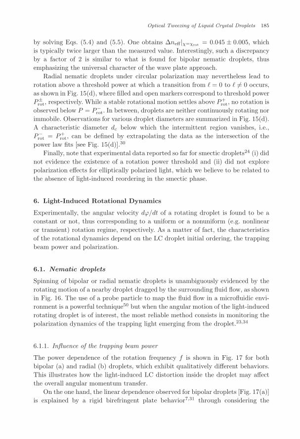
by solving Eqs. (5.4) and (5.5). One obtains ∆neff |χ=χrot = 0.045 ± 0.005, whichis typically twice larger than the measured value. Interestingly, such a discrepancyby a factor of 2 is similar to what is found for bipolar nematic droplets, thusemphasizing the universal character of the wave plate approach.
Radial nematic droplets under circular polarization may nevertheless lead torotation above a threshold power at which a transition from � = 0 to � �= 0 occurs,as shown in Fig. 15(d), where filled and open markers correspond to threshold powerP±
rot, respectively. While a stable rotational motion settles above P+rot, no rotation is
observed below P = P−rot. In between, droplets are neither continuously rotating nor
immobile. Observations for various droplet diameters are summarized in Fig. 15(d).A characteristic diameter dc below which the intermittent region vanishes, i.e.,P−
rot = P+rot, can be defined by extrapolating the data as the intersection of the
power law fits [see Fig. 15(d)].30
Finally, note that experimental data reported so far for smectic droplets24 (i) didnot evidence the existence of a rotation power threshold and (ii) did not explorepolarization effects for elliptically polarized light, which we believe to be related tothe absence of light-induced reordering in the smectic phase.
6. Light-Induced Rotational Dynamics
Experimentally, the angular velocity dϕ/dt of a rotating droplet is found to be aconstant or not, thus corresponding to a uniform or a nonuniform (e.g. nonlinearor transient) rotation regime, respectively. As a matter of fact, the characteristicsof the rotational dynamics depend on the LC droplet initial ordering, the trappingbeam power and polarization.
6.1. Nematic droplets
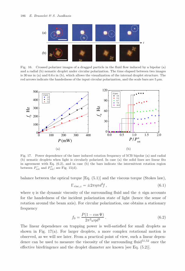
Spinning of bipolar or radial nematic droplets is unambiguously evidenced by therotating motion of a nearby droplet dragged by the surrounding fluid flow, as shownin Fig. 16. The use of a probe particle to map the fluid flow in a microfluidic envi-ronment is a powerful technique50 but when the angular motion of the light-inducedrotating droplet is of interest, the most reliable method consists in monitoring thepolarization dynamics of the trapping light emerging from the droplet.23,34
6.1.1. Influence of the trapping beam power
The power dependence of the rotation frequency f is shown in Fig. 17 for bothbipolar (a) and radial (b) droplets, which exhibit qualitatively different behaviors.This illustrates how the light-induced LC distortion inside the droplet may affectthe overall angular momentum transfer.
On the one hand, the linear dependence observed for bipolar droplets [Fig. 17(a)]is explained by a rigid birefringent plate behavior7,31 through considering the
July 11, 2009 10:58 WSPC/145-JNOPM 00458
186 E. Brasselet & S. Juodkazis
(a)
(b)
t
Fig. 16. Crossed polarizer images of a dragged particle in the fluid flow induced by a bipolar (a)and a radial (b) nematic droplet under circular polarization. The time elapsed between two imagesis 30ms in (a) and 0.6 s in (b), which allows the visualization of the internal droplet structure. Thered arrows indicate the handedness of the input circular polarization, and the scale bars are 5µm.
0 100 200 300 4000
100
200
300
400
500
fH
z
P (mW)
d (µm) 1.9 2.5 3.2
0
0.0 0.5 1.0 1.5 2.00
30
60
90
120
fH
z
P / Prot
d (µm) 4.8 5.4 6.7 7.8 10.2
+
0
(a) (b)
Fig. 17. Power dependence of the laser induced rotation frequency of 5CB bipolar (a) and radial(b) nematic droplets when light is circularly polarized. In case (a) the solid lines are linear fitsin agreement with Eq. (6.2), and in case (b) the bars indicate the intermittent rotation regionbetween P−
rot and P+rot; see Fig. 15(d).
balance between the optical torque [Eq. (5.1)] and the viscous torque (Stokes law),
Γvisc,z = ±2πηπd3f , (6.1)
where η is the dynamic viscosity of the surrounding fluid and the ± sign accountsfor the handedness of the incident polarization state of light (hence the sense ofrotation around the beam axis). For circular polarization, one obtains a stationaryfrequency
f0 =P (1 − cosΨ)
2π2ωηd3. (6.2)
The linear dependence on trapping power is well-satisfied for small droplets asshown in Fig. 17(a). For larger droplets, a more complex rotational motion isobserved, as we will see later. From a practical point of view, such a linear depen-dence can be used to measure the viscosity of the surrounding fluid51,52 once theeffective birefringence and the droplet diameter are known [see Eq. (5.2)].
July 11, 2009 10:58 WSPC/145-JNOPM 00458
Optical Tweezing of Liquid Crystal Droplets 187
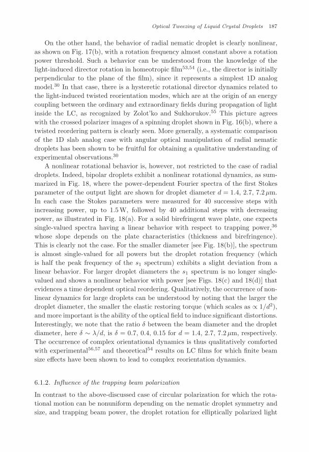
On the other hand, the behavior of radial nematic droplet is clearly nonlinear,as shown on Fig. 17(b), with a rotation frequency almost constant above a rotationpower threshold. Such a behavior can be understood from the knowledge of thelight-induced director rotation in homeotropic film53,54 (i.e., the director is initiallyperpendicular to the plane of the film), since it represents a simplest 1D analogmodel.30 In that case, there is a hysteretic rotational director dynamics related tothe light-induced twisted reorientation modes, which are at the origin of an energycoupling between the ordinary and extraordinary fields during propagation of lightinside the LC, as recognized by Zolot’ko and Sukhorukov.55 This picture agreeswith the crossed polarizer images of a spinning droplet shown in Fig. 16(b), where atwisted reordering pattern is clearly seen. More generally, a systematic comparisonof the 1D slab analog case with angular optical manipulation of radial nematicdroplets has been shown to be fruitful for obtaining a qualitative understanding ofexperimental observations.30
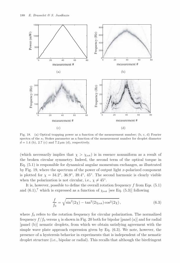
A nonlinear rotational behavior is, however, not restricted to the case of radialdroplets. Indeed, bipolar droplets exhibit a nonlinear rotational dynamics, as sum-marized in Fig. 18, where the power-dependent Fourier spectra of the first Stokesparameter of the output light are shown for droplet diameter d = 1.4, 2.7, 7.2µm.In each case the Stokes parameters were measured for 40 successive steps withincreasing power, up to 1.5W, followed by 40 additional steps with decreasingpower, as illustrated in Fig. 18(a). For a solid birefringent wave plate, one expectssingle-valued spectra having a linear behavior with respect to trapping power,36
whose slope depends on the plate characteristics (thickness and birefringence).This is clearly not the case. For the smaller diameter [see Fig. 18(b)], the spectrumis almost single-valued for all powers but the droplet rotation frequency (whichis half the peak frequency of the s1 spectrum) exhibits a slight deviation from alinear behavior. For larger droplet diameters the s1 spectrum is no longer single-valued and shows a nonlinear behavior with power [see Figs. 18(c) and 18(d)] thatevidences a time dependent optical reordering. Qualitatively, the occurrence of non-linear dynamics for large droplets can be understood by noting that the larger thedroplet diameter, the smaller the elastic restoring torque (which scales as ∝ 1/d2),and more important is the ability of the optical field to induce significant distortions.Interestingly, we note that the ratio δ between the beam diameter and the dropletdiameter, here δ ∼ λ/d, is δ = 0.7, 0.4, 0.15 for d = 1.4, 2.7, 7.2µm, respectively.The occurrence of complex orientational dynamics is thus qualitatively comfortedwith experimental56,57 and theoretical54 results on LC films for which finite beamsize effects have been shown to lead to complex reorientation dynamics.
6.1.2. Influence of the trapping beam polarization
In contrast to the above-discussed case of circular polarization for which the rota-tional motion can be nonuniform depending on the nematic droplet symmetry andsize, and trapping beam power, the droplet rotation for elliptically polarized light
July 11, 2009 10:58 WSPC/145-JNOPM 00458
188 E. Brasselet & S. Juodkazis
0 20 40 60 800
500
1000
1500
measurement #
Pow
er (
mW
)
0 20 40 60 800
200
400
600
800
measurement #
Freq
uenc
y (H
z)
(a) (b)
0 20 40 60 800
100
200
300
measurement #
Freq
uenc
y (H
z)
0 20 40 60 800
10
20
30
measurement #
Freq
uenc
y (H
z)
(c) (d)
Fig. 18. (a) Optical trapping power as a function of the measurement number; (b, c, d) Fourierspectra of the s1 Stokes parameter as a function of the measurement number for droplet diameterd = 1.4 (b), 2.7 (c) and 7.2µm (d), respectively.
(which necessarily implies that χ > χrot) is in essence nonuniform as a result ofthe broken circular symmetry. Indeed, the second term of the optical torque inEq. (5.1) is responsible for dynamical angular momentum exchanges, as illustratedby Fig. 19, where the spectrum of the power of output light x-polarized componentis plotted for χ = 34.2◦, 36.9◦, 39.4◦, 45◦. The second harmonic is clearly visiblewhen the polarization is not circular, i.e., χ �= 45◦.
It is, however, possible to define the overall rotation frequency f from Eqs. (5.1)and (6.1),7 which is expressed as a function of χrot [see Eq. (5.3)] following
f
f0=
√sin2(2χ) − tan2(2χrot) cos2(2χ) , (6.3)
where f0 refers to the rotation frequency for circular polarization. The normalizedfrequency f/f0 versus χ is shown in Fig. 20 both for bipolar [panel (a)] and for radial[panel (b)] nematic droplets, from which we obtain satisfying agreement with thesimple wave plate approach expression given by Eq. (6.3). We note, however, thepresence of a hysteresis behavior in experiments that is independent of the nematicdroplet structure (i.e., bipolar or radial). This recalls that although the birefringent
July 11, 2009 10:58 WSPC/145-JNOPM 00458
Optical Tweezing of Liquid Crystal Droplets 189
1.0 1.5 2.00
1
0/ ff
Px
spec
trum
1.0 1.5 2.00
1
0/ ffP
xsp
ectr
um
1.0 1.5 2.00
1
0/ ff
Px
spec
trum
1.0 1.5 2.00
1
0/ ff
Px
spec
trum
(a) (b) (c) (d)
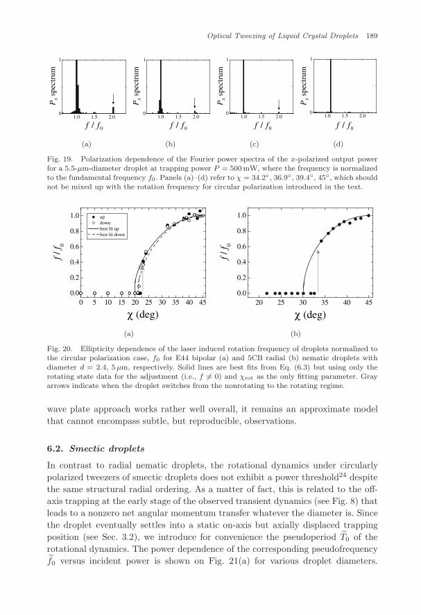
Fig. 19. Polarization dependence of the Fourier power spectra of the x-polarized output powerfor a 5.5-µm-diameter droplet at trapping power P = 500 mW, where the frequency is normalized
to the fundamental frequency f0. Panels (a)–(d) refer to χ = 34.2◦, 36.9◦, 39.4◦, 45◦, which shouldnot be mixed up with the rotation frequency for circular polarization introduced in the text.
0 5 10 15 20 25 30 35 40 450.0
0.2
0.4
0.6
0.8
1.0
(deg)χ
f / f 0
up down best fit up best fit down
χ20 25 30 35 40 45
0.0
0.2
0.4
0.6
0.8
1.0
(deg)
f / f 0
(a) (b)
Fig. 20. Ellipticity dependence of the laser induced rotation frequency of droplets normalized tothe circular polarization case, f0 for E44 bipolar (a) and 5CB radial (b) nematic droplets with
diameter d = 2.4, 5µm, respectively. Solid lines are best fits from Eq. (6.3) but using only therotating state data for the adjustment (i.e., f �= 0) and χrot as the only fitting parameter. Grayarrows indicate when the droplet switches from the nonrotating to the rotating regime.
wave plate approach works rather well overall, it remains an approximate modelthat cannot encompass subtle, but reproducible, observations.
6.2. Smectic droplets
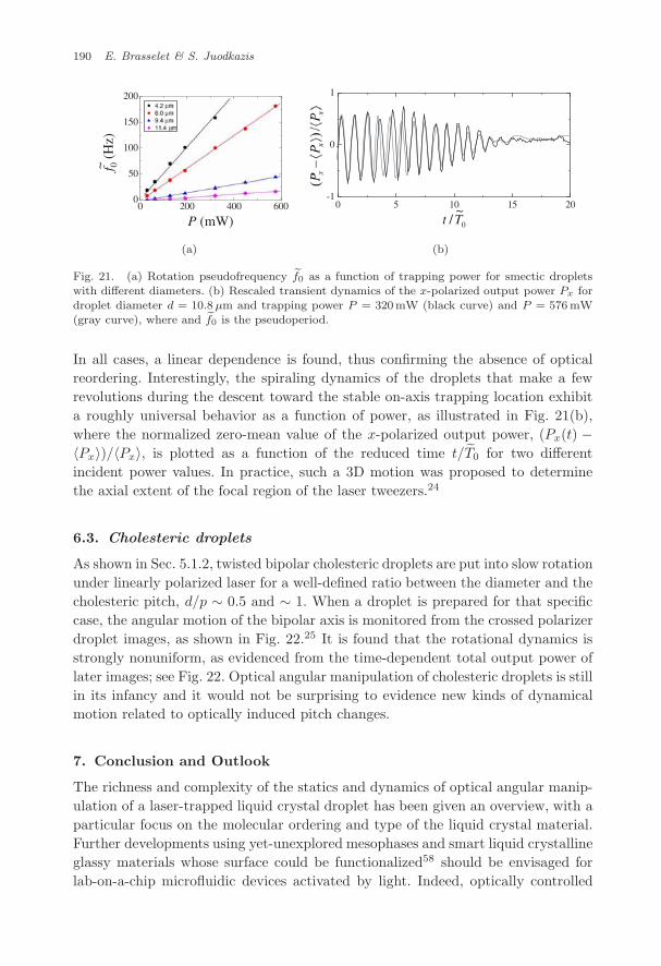
In contrast to radial nematic droplets, the rotational dynamics under circularlypolarized tweezers of smectic droplets does not exhibit a power threshold24 despitethe same structural radial ordering. As a matter of fact, this is related to the off-axis trapping at the early stage of the observed transient dynamics (see Fig. 8) thatleads to a nonzero net angular momentum transfer whatever the diameter is. Sincethe droplet eventually settles into a static on-axis but axially displaced trappingposition (see Sec. 3.2), we introduce for convenience the pseudoperiod T0 of therotational dynamics. The power dependence of the corresponding pseudofrequencyf0 versus incident power is shown on Fig. 21(a) for various droplet diameters.
July 11, 2009 10:58 WSPC/145-JNOPM 00458
190 E. Brasselet & S. Juodkazis
0 200 400 6000
50
100
150
200
P (mW)
f 0(H
z)~
0 5 10 15 20-1
0
1
0/Tt~
(a) (b)
Fig. 21. (a) Rotation pseudofrequency ef0 as a function of trapping power for smectic dropletswith different diameters. (b) Rescaled transient dynamics of the x-polarized output power Px fordroplet diameter d = 10.8µm and trapping power P = 320mW (black curve) and P = 576 mW(gray curve), where and ef0 is the pseudoperiod.
In all cases, a linear dependence is found, thus confirming the absence of opticalreordering. Interestingly, the spiraling dynamics of the droplets that make a fewrevolutions during the descent toward the stable on-axis trapping location exhibita roughly universal behavior as a function of power, as illustrated in Fig. 21(b),where the normalized zero-mean value of the x-polarized output power, (Px(t) −〈Px〉)/〈Px〉, is plotted as a function of the reduced time t/T0 for two differentincident power values. In practice, such a 3D motion was proposed to determinethe axial extent of the focal region of the laser tweezers.24
6.3. Cholesteric droplets
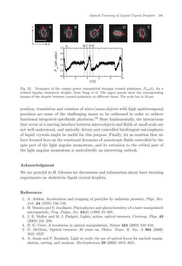
As shown in Sec. 5.1.2, twisted bipolar cholesteric droplets are put into slow rotationunder linearly polarized laser for a well-defined ratio between the diameter and thecholesteric pitch, d/p ∼ 0.5 and ∼ 1. When a droplet is prepared for that specificcase, the angular motion of the bipolar axis is monitored from the crossed polarizerdroplet images, as shown in Fig. 22.25 It is found that the rotational dynamics isstrongly nonuniform, as evidenced from the time-dependent total output power oflater images; see Fig. 22. Optical angular manipulation of cholesteric droplets is stillin its infancy and it would not be surprising to evidence new kinds of dynamicalmotion related to optically induced pitch changes.
7. Conclusion and Outlook
The richness and complexity of the statics and dynamics of optical angular manip-ulation of a laser-trapped liquid crystal droplet has been given an overview, with aparticular focus on the molecular ordering and type of the liquid crystal material.Further developments using yet-unexplored mesophases and smart liquid crystallineglassy materials whose surface could be functionalized58 should be envisaged forlab-on-a-chip microfluidic devices activated by light. Indeed, optically controlled
July 11, 2009 10:58 WSPC/145-JNOPM 00458
Optical Tweezing of Liquid Crystal Droplets 191
0 2 4 6 8 100.0
0.2
0.4
0.6
0.8
1.0
t (s)
P out(a
rb.u
nits
)
A B C D Ex
y A B C D E
Fig. 22. Dynamics of the output power transmitted through crossed polarizers, Pout(t), for atwisted bipolar cholesteric droplet, from Yang et al. The upper panels show the correspondingimages of the droplet between crossed polarizers at different times. The scale bar is 10 µm.
position, translation and rotation of micro/nano-objects with high spatiotemporalprecision are some of the challenging issues to be addressed in order to achievefunctional integrated optofluidic platforms.59 More fundamentally, the interactionsthat occur at a moving interface between micro-objects and fluids at small scale arenot well-understood, and optically driven and controlled birefringent microspheresof liquid crystals might be useful for this purpose. Finally, let us mention that wehave focused here on the rotational dynamics of anisotropic fluids controlled by thespin part of the light angular momentum, and its extension to the orbital part ofthe light angular momentum is undoubtedly an interesting outlook.
Acknowledgment
We are grateful to H. Gleeson for discussions and information about laser tweezingexperiments on cholesteric liquid crystal droplets.
References
1. A. Ashkin, Acceleration and trapping of particles by radiation pressure, Phys. Rev.Lett. 24 (1970) 156–159.
2. H. Misawa and S. Juodkazis, Photophysics and photochemistry of a laser manipulatedmicroparticle, Prog. Polym. Sci. 24(6) (1999) 65–697.
3. J. E. Molloy and M. J. Padgett, Lights, action: optical tweezers, Contemp. Phys. 43(2002) 241–258.
4. D. G. Grier, A revolution in optical manipulation, Nature 424 (2003) 810–816.5. D. McGloin, Optical tweezers: 20 years on, Philos. Trans. R. Soc. A 364 (2006)
3521–3537.6. A. Jonas and P. Zemanek, Light at work: the use of optical forces for particle manip-
ulation, sorting, and analysis, Electrophoresis 29 (2008) 4813–4851.
July 11, 2009 10:58 WSPC/145-JNOPM 00458
192 E. Brasselet & S. Juodkazis
7. M. E. J. Friese, T. A. Nieminen, N. R. Heckenberg and H. Rubinsztein-Dunlop, Opticalalignment and spinning of laser-trapped microscopic particles, Nature 394 (1998) 348–350.
8. P. G. de Gennes, The Physics of Liquid Crystals, 2nd edn. (Clarendon Press, Oxford,1993).
9. P. Poulin, H. Stark, T. C. Lubensky and D. A. Weitz, Novel colloidal interactions inanisotropic fluids, Science 275 (1997) 1770–1773.
10. I. Musevic, M. Skarabot, D. Babic, N. Osterman, I. Poberaj, V. Nazarenko and A.Nych, Laser trapping of small colloidal particles in a nematic liquid crystal: cloudsand ghosts, Phys. Rev. Lett. 93 (2004) 187801.
11. I. I. Smalyukh, A. V. Kachynski, A. N. Kuzmin and P. N. Prasad, Laser trappingin anisotropic fluids and polarization-controlled particle dynamics, Proc. Natl. Acad.Sci. U.S.A. 103 (2006) 18048–18053.
12. Y. Iwashita and H. Tanaka, Optical manipulation of defects in a lyotropic lamellarphase, Phys. Rev. Lett. 90 (2003) 045501.
13. H. F. Gleeson, T. A. Wood and M. Dickinson, Laser manipulation in liquid crystals:an approach to microfluidics and micromachines, Philos. Trans. R. Soc. A 364 (2006)2789–2805.
14. M. Yada, J. Yamamoto and H. Yokoyama, Direct observation of anisotropic inter-particle forces in nematic colloids with optical tweezers, Phys. Rev. Lett. 92 (2004)185501.
15. J.-I. Hotta, K. Sasaki and H. Masuharaa, Manipulation of liquid crystal textures witha focused near infrared laser beam, Appl. Phys. Lett. 15 (1997) 2085–2087.
16. A. Pattanaporkratana, C. S. Park, J. E. Maclennan and N. A. Clark, Manipulation ofdisk-shaped islands on freely suspended smectic films and CDs using optical tweezers,Ferroelectrics 310 (2004) 131–135.
17. I. I. Smalyukh, B. I. Senyuk, S. V. Shiyanovskii, O. D. Lavrentovich, A. N. Kuzmin,A. V. Kachynski and P. N. Prasad, Optical trapping, manipulation, and 3D imagingof disclinations in liquid crystals and measurement of their line tension, Mol. Cryst.Liq. Cryst. 450 (2006) 79–95.
18. I. I. Smalyukh, D. S. Kaputa, A. V. Kachynski, A. N. Kuzmin and P. N. Prasad, Opti-cal trapping of director structures and defects in liquid crystals using laser tweezers,Opt. Express 15 (2007) 4359–4371.
19. T. G. Mason and J. Bibette, Emulsification in viscoelastic media, Phys. Rev. Lett. 77(1996) 3481–3484.
20. A. Fernandez-Nieves, G. Cristobal, V. Garces-Chavez, G. C. Spalding, K. Dholakiaand D. A. Weitz, Optically anisotropic colloids of controllable shape, Adv. Mater.17(6) (2005) 680–684.
21. S. Juodkazis, M. Shikata, T. Takahashi, S. Matuso and H. Misawa, Fast optical switch-ing by a laser-manipulated microdroplet of liquid crystal, Appl. Phys. Lett. 74 (1999)3627–3629.
22. S. Juodkazis, S. Matuso, N. Murazawa, I. Hasegawa and H. Misawa, High-efficiencyoptical transfer of torque to a nematic liquid crystal droplet, Appl. Phys. Lett. 82(2003) 4657–4659.
23. T. A. Wood, H. F. Gleeson, M. R. Dickinson and A. J. Wright, Mechanisms of opticalangular momentum transfer to nematic liquid crystalline droplets, Appl. Phys. Lett.84 (2004) 4292–4294.
24. N. Murazawa, S. Juodkazis and H. Misawa, Laser-manipulation of a smectic liquidcrystal droplet, Eur. Phys. J. E 20 (2006) 435–439.
July 11, 2009 10:58 WSPC/145-JNOPM 00458
Optical Tweezing of Liquid Crystal Droplets 193
25. Y. Yang, P. D. Brimicombe, N. W. Roberts, M. R. Dickinson, M. Osipov and H. F.Gleeson, Continuously rotating chiral liquid crystal droplets in a linearly polarizedlaser trap, Opt. Express 16 (2008) 6877–6882.
26. N. V. Tabiryan, A. V. Sukhov and B. Ya. Zel’dovich, The orientational optical non-linearity of liquid crystals, Mol. Cryst. Liq. Cryst. 136 (1986) 1–139.
27. I. C. Khoo, Nonlinear optics of liquid crystalline materials Phys. Rep. 471(5–6) (2009)221–267.
28. N. Murazawa, S. Juodkazis, S. Matuso and H. Misawa, Control of the molecularalignment inside liquid crystal droplets by use of laser tweezers, Small 1 (2005) 656–661.
29. N. Murazawa, S. Juodkazis and H Misawa, Laser manipulation based on a light-induced molecular reordering, Opt. Express 14 (2006) 2481–2486.
30. E. Brasselet, N. Murazawa, S. Juodkazis and H. Misawa, Phys. Rev. E 77 (2008)041704.
31. C. Manzo, D. Paparo, L. Marrucci and I. Janossy, Light-induced rotation of dye-dopedliquid crystal droplets, Phys. Rev. E 73 (2006) 051707.
32. I. Janossy, A. D. Lloyd and B. S. Wherrett, Anomalous optical Freedericksz transitionin an absorbing liquid crystal, Mol. Cryst. Liq. Cryst. 179 (1990) 1–12.
33. I. Janossy and T. Kosa, Influence of anthraquinone dyes on optical reorientation ofnematic liquid crystals, Opt. Lett. 17 (1992) 1183–1185.
34. N. Murazawa, S. Juodkazis and H. Misawa, Characterization of bipolar and radialnematic liquid crystal droplets using laser-tweezers, J. Phys. D 38 (2005) 2923–2927.
35. F. Xu and P. P. Crooker, Chiral nematic droplets with parallel surface anchoring,Phys. Rev. E 56 (1997) 6853–6860.
36. E. Brasselet, T. Balciunas, N. Murazawa, S. Juodkazis and H. Misawa, Light-inducednonlinear rotations of nematic liquid crystal droplets trapped in laser tweezers, Mol.Cryst. Liq. Cryst., in press.
37. J. P. Barton, D. R. Alexander and S. A. Schaub, Theoretical determination of netradiation force and torque for a spherical particle illuminated by a focused laser beam,J. Appl. Phys. 66 (1989) 4594–4602.
38. K. Ren, G. Grehan and G. Gouesbet, Radiation pressure forces exerted on a particlearbitrarily located in a Gaussian beam by using the generalized Lorenz–Mie theory,and associated resonance effects, Opt. Commun. 108 (1994) 343–354.
39. T. A. Nieminen, H. Rubinsztein-Dunlop, N. R. Heckenberg and A. I. Bishop, Numer-ical modelling of optical trapping, Comput. Phys. Commun. 142 (2001) 468–471.
40. S. H. Simpson and S. Hanna, Optical trapping of spheroidal particles in Gaussianbeams, J. Opt. Soc. Am. A 24 (2007) 430–443.
41. S. H. Simpson and S. Hanna, Rotation of absorbing spheres in Laguerre Gaussianbeams, J. Opt. Soc. Am. A 26 (2009) 173–183.
42. S. H. Simpson and S. Hanna, Optical angular momentum transfer by Laguerre Gaus-sian beams, J. Opt. Soc. Am. A 26 (2009) 625–638.
43. M. I. Mishchenko, L. D. Travis and A. A. Lacis, Scattering, Absorption and Emissionof Light by Small Particles (Cambridge University Press, 2002).
44. I. Janossy, Electromagnetic torque and force in axially symmetric liquid crystaldroplets, Opt. Lett. 33 (2008) 2371–2373.
45. E. Brasselet, D. O. Krimer and L. Kramer, Light-induced instabilities driven by com-peting helical patterns in long-pitch cholesterics, Eur. Phys. J. E 17 (2005) 403–411.
46. E. Santamato, A. Sasso, B. Piccirillo and A. Vella, Optical angular momentum trans-fer to transparent isotropic particles using laser beam carrying zero average angularmomentum, Opt. Express 10 (2002) 871–878.
July 11, 2009 10:58 WSPC/145-JNOPM 00458
194 E. Brasselet & S. Juodkazis
47. A. I. Bishop, T. A. Nieminen, N. R. Heckenberg and H. Rubinsztein-Dunlop, Opticalapplication and measurement of torque on microparticles of isotropic nonabsorbingmaterial, Phys. Rev. A 68 (2003) 033802.
48. R. Dasgupta and P. K. Gupta, Rotation of transparent, non-birefringent objects bytransfer of the spin angular momentum of light, Opt. Lett. 30 (2005) 394–396.
49. A. Yu. Savchenko, N. V. Tabiryan and B. Ya. Zel’dovich, Transfer of momentum andtorque from a light beam to a liquid, Phys. Rev. E 56 (1997) 4773–4779.
50. R. Di Leonardo, J. Leach, H. Mushfique, J. M. Cooper, G. Ruocco and M. J. Padgett,Multipoint holographic optical velocimetry in microfluidic systems, Phys. Rev. Lett.96 (2006) 134502.
51. N. Murazawa, S. Juodkazis, V. Jarutis, Y. Tanamura and H. Misawa, Viscosity mea-surement using a rotating laser-trapped microsphere of liquid crystal, Europhys. Lett.73 (2006) 800–805.
52. N. Murazawa, S. Juodkazis, Y. Tanamura and H. Misawa, Rheology measurementat liquid-crystal water interface using laser tweezers, Jpn. J. Appl. Phys. 45 (2006)977–982.
53. E. Brasselet, T. V. Galstian, L. J. Dube, D. O. Krimer and L. Kramer, Bifurcationanalysis of optically induced dynamics in nematic liquid crystals: circular polarizationat normal incidence, J. Opt. Soc. Am. B 22 (2005) 1671–1680.
54. E. Brasselet, B. Piccirillo and E. Santamato, Three-dimensional model for light-induced chaotic rotations in liquid crystals under spin and orbital angular momentumtransfer processes, Phys. Rev. E 78 (2008) 031703.
55. A. S. Zolotko and A. P. Sukhorukov, Freedericksz transition induced in nematic liquidcrystal by circularly polarized light wave, Pis’ma Zh. Eksp. Teor. Fiz 52 (1990) 707–710 [JETP Lett. 52 (1990) 62–65].
56. A. Vella, A. Setaro, B. Piccirillo and E. Santamato, On–off intermittency in chaoticrotation induced in liquid crystals by competition between spin and orbital angularmomentum of light, Phys. Rev. E 67 (2003) 051704.
57. E. Brasselet and L. J. Dube, Light-induced chaotic rotations in nematic liquid crystals,Phys. Rev. E 73 (2006) 021704.
58. V. A. Mallia and N. Tamaoki, Design of chiral dimesogens containing cholesterylgroups; formation of new molecular organizations and their application to molecularphotonics, Chem Soc. Rev. 33(2) (2004) 76–84.
59. C. Monat, P. Domachuk and B. J. Eggleton, Integrated optofluidics: a new river oflight, Nat. Photon. 1 (2007) 106–114.