Embed Size (px)
DESCRIPTION
journl on mfg
Citation preview

Robotics and Computer-Integrated Manufacturing 29 (2013) 23–38
Contents lists available at SciVerse ScienceDirect
Robotics and Computer-Integrated Manufacturing
0736-58
http://d
n Corr
E-m
journal homepage: www.elsevier.com/locate/rcim
An adaptive process planning approach of rapid prototypingand manufacturing
G.Q. Jin a, W.D. Li a,n, L. Gao b
a Faculty of Engineering and Computing, Coventry University, Coventry CV1 5FB, UKb State Key Laboratory of Digital Manufacturing Equipment and Technology, Huazhong University of Science and Technology, Wuhan 430074, PR China
a r t i c l e i n f o
Article history:
Received 23 February 2012
Received in revised form
8 June 2012
Accepted 2 July 2012Available online 13 August 2012
Keywords:
Rapid prototyping
Rapid manufacturing
Process planning
Tool-path generation
Biomedical model
45/$ - see front matter & 2012 Elsevier Ltd. A
x.doi.org/10.1016/j.rcim.2012.07.001
esponding author. Tel.: þ44 2476 88 8940.
ail address: [email protected] (W.D.
a b s t r a c t
This paper presents an adaptive approach to improve the process planning of Rapid Prototyping/
Manufacturing (RP/M) for complex product models such as biomedical models. Non-Uniform Rational
B-Spline (NURBS)-based curves were introduced to represent the boundary contours of the sliced layers
in RP/M to maintain the geometrical accuracy of the original models. A mixed tool-path generation
algorithm was then developed to generate contour tool-paths along the boundary and offset curves of
each sliced layer to preserve geometrical accuracy, and zigzag tool-paths for the internal area of the
layer to simplify computing processes and speed up fabrication. In addition, based on the developed
build time and geometrical accuracy analysis models, adaptive algorithms were designed to generate
an adaptive speed of the RP/M nozzle/print head for the contour tool-paths to address the geometrical
characteristics of each layer, and to identify the best slope degree of the zigzag tool-paths towards
achieving the minimum build time. Five case studies of complex biomedical models were used to verify
and demonstrate the improved performance of the approach in terms of processing effectiveness and
geometrical accuracy.
& 2012 Elsevier Ltd. All rights reserved.
1. Introduction
Before undergoing complex operations, surgeons usuallyexperience difficulties in figuring out the exact location/profileof a defect or developing a precise implant for a patient. As aninnovative manufacturing technology [1], Rapid Prototyping/Manufacturing (RP/M) can enable a surgeon to practice on atangible prototyping model in order to understand details beforeactual operations and is efficiently used to fabricate a customizedimplant suitable for a patient. Different from conventional form-ing and machining processes, RP/M is an additive manufacturingprocess by adding materials layer-by-layer to build up complexmodels such as biomedical models digitally represented inComputer-Aided Design (CAD) systems. The distinguished advan-tage of RP/M is that it is a mold-less process, suitable for free-form and complex geometrical model realization [2]. Biomedicalmodels are usually characterized with highly customized andcomplex geometry, and the research to exploit the RP/M technol-ogy to support biomedical applications is becoming increasinglyactive in recent years [3]. Otherwise, for complex biomedicalmodels, the current process planning strategies in RP/M softwarepackages need to be improved significantly in the aspects of build
ll rights reserved.
Li).
time and geometrical quality. Meanwhile, geometrical errorsinherent from the layer-by-layer and additive forming mechan-ism of RP/M have brought challenges on achieving high geome-trical quality of biomedical products. Owing to quickly developedhealthcare markets with stronger requirements for more complexapplications, it is becoming a strong desire to develop betteralgorithms and strategies in RP/M to reduce build time andimprove geometrical accuracy so as to meet the high-qualitydesign and functional requirements of complex biomedicalmodels [4].
Process planning is a critical task in RP/M. A good process plancan lead to a high-quality product model. Orientation determina-tion, support structure determination, slicing and tool-pathgeneration are four essential steps in process planning (shownin Fig. 1). For some RP/M techniques such as Wire and ArcAdditive Manufacturing (WAAM) [5], support structure is not anissue, while for other RP/M techniques such as powder deposition,orientation determination, which is used to define the slicingdirection of a RP/M model, will affect the support structure designof the model, the profile complexity and the total number ofsliced layers, and further the build time and geometrical quality ofthe model. Support structures are used to uphold overhangingbuild materials during RP/M forming to avoid structural collapseor deformation of the model. An optimal structure can ensureshort build time, high geometrical quality and good mechanicalproperties of the model [6]. Slicing is to transfer a product model

CADModels
Orientationdetermination
Supportstructure
determinationSlicing
Tool-pathgeneration 3D Printer
Fused DepositionModeling (FDM)
Selective LaserSintering/Melting
(SLS/SLM)
etc.
Process planning Rapid Prototyping/Manufacturing systems
Fig. 1. Process planning for RP/M systems.
Table 1A summary of RP/M model representation.
Research Original models RP/M models Major characteristics
Chen and Shi [19,20] PowerSHAPE
models
Lines, arcs and Bezier
curves for sliced
contours
A macro-AutoSection software package was developed to collect sliced
contour data and produce PIC files; Another software package PDSlice
was devised to support the RP/M process.
Cao and Miyamoto [21] AutoCAD models Lines, arcs, circles for
sliced contours
An ASCII DXF file was used to store sliced layer data. Material information
can also be stored in this file.
Ma et al. [22] 3D CAD models NURBS representation
for sliced contours
A NURBS surface model was used to obtain more accurate and smoother
surface for RP/M, and a selective hatching strategy was developed to
further reduce build time and improve geometrical quality.
Starly et al. [23] 3D CAD models STEP based NURBS-
represented contours
A slicing algorithm was designed to determine the optimal direction, and an
adaptive subdivision strategy was also applied for geometrical refinement.
Yin [24] Point cloud data NURBS or Bezier-
based sliced contours
An approach was developed to build a bridge between scattered points
and a slicing algorithm was designed to integrate RE-based data and RP/
M to reduce modeling time.
Liu et al. [25] Contour data from
digital camera
STL files A NC milling machine and a digital camera were used to capture the
cross-sectional images of a model used to generate the contour data for
directly adaptive slicing to reduce modeling time.
G.Q. Jin et al. / Robotics and Computer-Integrated Manufacturing 29 (2013) 23–3824
into a series of 2D sliced layers perpendicular to the orientationdirection with a pre-defined or adaptively adjusted layer thick-ness. If each layer is too thick, the build time is reduced but thegeometrical accuracy of the product could be relatively poor.Otherwise, the geometrical accuracy is improved but the buildtime is also extended [7,8]. A tool-path is the trajectory of thenozzle (e.g., in a Fused Deposition Modeling (FDM) system)/printhead (e.g., in a 3D Printer) in a RP/M process to fill the boundaryand interior areas of each sliced layer. A tool-path strategyincludes the determination of the topological, geometrical andprocess parameters. Various types of tool-path strategies andalgorithms such as zigzag, contour, spiral and partition patternswere developed with different considerations on the build time,cost, geometrical quality, warpage, shrinkage, strength and stiff-ness of a RP/M model [9–15].
The research presented in this paper focuses on addressing themajor issue of RP/M process planning, and a systematic approachwas developed to improve the RP/M model representation, tool-pathgeneration and nozzle/print head speed to adapt to the variousgeometrical properties of complex product models such as biomedi-cal models. The approach includes the following algorithms:
(1)
A Non-Uniform Rational B-Spline (NURBS)-based slicingalgorithm—used to convert a product model to a series of2D parametric contours of sliced layers. The algorithmenhances the representation accuracy of the model duringRP/M and replaces Stereolithography (STL)-based representa-tion strategy, which is a de facto but less accurate standard tosupport RP/M in industries.(2)
A mixed tool-path generation algorithm—used to generate aseries of contour and offset tool-paths along the NURBS-basedrepresented boundary of the model to improve the geome-trical quality during RP/M, and zigzag tool-paths for theinternal area of the model to simplify computing and fabrica-tion processes.(3)
An adaptive speed algorithm for RP/M—used to control thespeed of the RP/M nozzle/print head adaptively for thevarious geometries of the model so as to improve theefficiency of contour tool-paths, and to determine the slopedegree of zigzag tool-paths leading to the shortest build time.In the end, five case studies of complex biomedical models wereused to verify and demonstrate the performance of this research interms of processing efficiency and geometrical accuracy.
2. Related works
2.1. RP/M model representation
STL, which has been a widely adopted data standard in the RP/M industry, is an approximation representation scheme of productmodels based on triangles or quadrilaterals. However, there aresome intrinsic problems in STL files such as gaps, holes, missing/degenerated/overlapping facets, etc. during the conversion processfrom native CAD files. Therefore, repairing algorithms of errors inSTL files and simplification algorithms of STL files were developed[16–18]. On the other hand, STL is less inaccurate in geometricalrepresentation and needs much more storage spaces for a complexmodel than parametric mathematical representation themes suchas NURBS, Bezier, B-Spline, etc. Recently, there are active researchand development to introduce parametric mathematical repre-sentation to better support RP/M. A short summary of the previouswork is given in Table 1, and the detailed discussions areexpanded below. The tables in Section 2 are not comprehensiveand for indication.
In Chen and Shi’s approaches, arcs, lines and Bezier curves wereused to describe the cross-sectional contour geometries of slicedlayers [19,20]. A macro-AutoSection software package was developedto collect the sliced contour data, and a software package, i.e.,

G.Q. Jin et al. / Robotics and Computer-Integrated Manufacturing 29 (2013) 23–38 25
PDSlice, was devised to support the RP/M process for a commercialSelective Laser Sintering (SLS) machine called HRPD-III. Some proto-types were fabricated to demonstrate that the proposed mathema-tical representation improved the accuracy and quality of complexproducts compared to the STL format. Cao and Miyamoto [21]developed an approach to use lines, arcs and circles to representthe sliced contours of an AutoCAD solid model in an ASCII DXF file.Material information such as material type can also be saved in thisapproach to support RP/M. Ma et al. [22] used NURBS to represent aRP/M model so as to obtain more accurate and smoother surface, andapplied a selective hatching strategy to further reduce build time andimprove geometrical quality by fabricating the kernel region of themodel using thicker sliced layers and the skin region of the modelusing thinner sliced layers. Starly et al. [23] developed a slicingalgorithm to represent a RP/M model as a STEP- and NURBS-represented model. The algorithm is comprised of five steps: (1) todetermine the orientation of a model to minimize build height, (2) todefine the NURBS surface of the model, (3) to generate a boundaryvolume data structure, (4) to use a bi-sectional iteration routinemethod to solve the inter-sectional points, and (5) to categorizeinter-sectional points to support an optimized RP/M process. Fourmodels in different representation formats were used to validate thedeveloped algorithm.
Some researchers also developed methods to integrate theReverse Engineering (RE) technology and RP/M representation bymodeling point cloud data generated by a Coordinate Measure-ment Machine (CMM) to support RP/M. The research reduces themodeling time and shortens the overall time-to-market forRE-based products. Yin [24] developed a novel algorithm to builda bridge between scattered points and a slicing algorithm tointegrate RE-based data and RP/M. The steps to carry out the workare: (1) work piece digitization, (2) segmentation, (3) NURBS orB-Spline-based surface construction based on the segmentedcloud data, and (4) slicing processing. Liu et al. [25] presentedan approach to generate a RP/M slicing file directly from imagedata. A digital camera was used to capture the cross-sectionalimages of a RE-based product. The contour data of the productwas computed and an algorithm was developed to generate a STLfile and a RP/M slicing file from the contour data.
Some of the above research successfully adopted parametricrepresentation such as Bezier, B-Spline and NURBS to improve thegeometrical quality of RP/M models. However, a research gapexists between the parametric representation and the followingprocess planning, and a smart solution is imperative to addressthe different geometrical characteristics of complex biomedicalmodels in order to improve the build efficiency and geometricalaccuracy of RP/M.
2.2. RP/M tool-path generation
A tool-path is the trajectory of the nozzles/print head in a RP/Mprocess to fill the boundary and interior of each sliced layer.
Table 2A summary of RP/M tool-path generation.
Works Tool-path patterns Major characteristics
Misra and Chang [9,10] Zigzag The approach fills a laye
but poor on geometrica
Yang and Genesan [11,12] Contour The approach builds a l
ensures good geometric
generation.
Bertoldi et al. [13] Recursive Hilbert’s curve More suitable for some
than that of other conv
Lou et al. [14] Spiral More suitable for some
Chiu et al. [15] Fractal curve It is only suitable for so
It is an important factor that affects the geometrical quality,strength and stiffness of a building model, and efficiency of theRP/M process. There are various types of tool-path patternsdeveloped for RP/M, such as zigzag, contour, spiral and somespace filling curves. A summary is shown in Table 2, and moreexplanations are given below.
The zigzag tool-path generation is the most typical method usedin RP/M systems. It fills models line-by-line along the X or Y direction[9,10] This method is easy to implement, but it has the followingdrawbacks: (1) if a model for RP/M is complex or has some hollowstructures inside, the tools such as the laser of SLS/Selective LaserMelting (SLM) and the nozzle of FDM have to be turned frequently,leading to a poor building quality; (2) the model will have a warpageproblem as the tool-path will be along the same direction to buildthe whole model. The contour tool-path generation, which is anothertypical method, can address the above geometrical quality issueeffectively by following the geometrical trend of the boundarycontours [11,12]. Meanwhile, the method overcomes the warpageproblem as the tool-path direction is changed constantly along thecontour curves of sliced layers. However, when a boundary contouris irregular or has a hollow, island or ring structure such asbiomedical models, the computation of the algorithms will becomplicated. In a number of biomedical cases, the algorithms areunable to generate proper contour tool-paths.
Some space filling curves with pre-defined shapes were also beenused for the tool-path generation in RP/M for some special purposessuch as strength, stiffness and model bonding. Bertoldi et al. [13]developed a fractal approach to generate Hilbert curve-based tool-paths for a FDM RP/M system. The method can reduce shrinkageduring RP/M fabrication process but build time will be longer thanthat of traditional tool-path generation methods. The spiral tool-pathgeneration as used by Lou et al. [14] was widely applied in NCmachining, especially for 2D pocket milling and uniform pocketcutting. It can also be applied to solve the problems of zigzag tool-paths in the FDM process, but be more suitable for some specialgeometrical models due to complex computation [8]. Chiu et al. [15]proposed a novel method to generate the tool-path of RP/M from themathematical model of a fractal model. It first generates a slab gridin each layer that consists of a number of pixels, and then checks theinterior property of each pixel in the slab grid to create the slabmodel of the fractal object. The boundary of slab model is refined andthe tool-path of RP/M can be generated from these boundaries.However, these research works are only suitable for fractal models.
Based on the potentials of the above research in differentconditions, it is expected to develop a smart and hybrid strategyto leverage the advantages of various tool-path generation stra-tegies to be suitable for complex models in the RP/M processes.
2.3. RP/M build time and geometrical accuracy analysis strategies
The build time is an important factor to be considered in RP/M.Some build time analysis and prediction models were developed
r along the X, Y or a specific direction, and it is easy for approach implementation
l quality.
ayer along its contour and offset curves following the boundary of the model. It
al quality but takes longer during model build compared to the zigzag tool-path
regular boundaries and special geometric models. The build time will be longer
entional tool-path generation methods.
special geometrical models due to improved computation.
me special fractal models.

Table 3A summary of RP/M build time and geometrical accuracy analysis models (J means the chosen analysis model).
Works Buildtime
Geometricalaccuracy
Major characteristics
Chen and Sullivan
[26]
J To predict the build time of a SLS process with different laser powers, beam diameters and input cure
depths.
Han et al. [27] J To calculate the build time for a FDM process by separating it as a deposition time and an idle time.
A nozzle repositioning time and a cleaning time were also taken into account.
Wah et al. [28] J Two enhanced GA algorithms were used to reduce build time for non-fabrication motion of a RP/M system.
Castelino et al. [29] J An algorithm was developed for minimizing non-fabrication time by optimally connecting different
tool-path segments.
Liu et al. [30,31] J To predict the geometrical errors of a RP/M process with profiling error, layer inclination and layer t
hickness variations.
Bacchewar et al. [32] J Surface roughness was studied based on a set of process parameters such as build orientation,
laser power, layer thickness, beam speed, and hatch spacing for obtaining the best
surface finish in a SLS process.
Armillotta [33] J The approach verifies surface quality with different texture dimensional parameters
on textured surfaces of a model.
G.Q. Jin et al. / Robotics and Computer-Integrated Manufacturing 29 (2013) 23–3826
(a summary is in Table 3). Chen and Sullivan [26] did a detailed studyof the laser scan mechanism in a SLS process. Based on themeasurement results of different scan patterns and curing depths,formulas were developed to predict the total build time and theresultant curing depth for different laser powers, beam diameters andinput curing depths of the SLS process. However, only the total laserscan time and total recoating time were considered, and more factorscontributing to the total build time need to be incorporated to furtherimprove the predictor. Han et al. [27] presented a build time analysismodel for a FDM process. In the method, apart from the depositiontime and idle time, nozzle repositioning time and cleaning time werealso taken into account in the analysis model. Some parameterswhich can be used to speed up the build time of FDM, including layerthickness, road width, table speed and repositioning distance wereidentified. However, the research is specific for some deposition-based RP/M processes.
Some heuristics algorithms were designed to minimize thetime spent on the non-fabrication motion of tool-path generationduring the RP/M process. Wah et al. [28] combined the Asym-metric Traveling Salesman Problem and Integer Programming(TSP-IP) for the time model. Based on the model, two enhancedGenetic Algorithms (GA) were introduced to achieve the mini-mum time of the non-fabrication motion of RP/M. Castelino et al.[29] developed an algorithm for minimizing non-fabrication timeby optimally connecting different tool-path segments. The non-fabrication time problem was first formulated as a standard TSPproblem with precedence constraints, and then some heuristicmethods were applied to solve this problem. However, themethod is difficult to be applied to complex biomedical modelswhich include hollows and complex contours.
The geometrical quality is another important factor in RP/M [2].Liu et al. [30,31] studied the geometrical errors interaction andtransferring mechanisms in the RP/M process. A physical model wasused to define the error interactions and transferring mechanisms.Based on the geometrical approximation techniques, a geometricalmodel was developed to describe the relationships of geometricalerrors. A mathematical model was then developed to analyze theeffect of transformation of local errors to multiple layer globalerrors. However, the described geometrical errors only involveprofiling error, layer inclination and layer thickness variations. Otherelements that affect the geometrical accuracy of RP/M processshould be added to further improve the mathematical analysismodel. Bacchewar et al. [32] studied the effect of process parameterson the surface roughness of SLS with the help of central rotatablecomposite design (CCD) of experiments. Analysis of variance(ANOVA) was used to study various surface roughness based ondifferent build orientation, laser power, layer thickness, beam speed,
and hatch spacing. A trust-region-based optimization method wasemployed to obtain a set of process parameters for obtaining thebest surface finish. Armillotta [33] proposed an approach to assesssurface quality on textured surface in a FDM system. A benchmarkpolygon model with different feature sizes and aspect ratios wasfabricated in a FDM system with different build orientations. Itanalyzed the verification of surface quality with different texturedimensional parameters on textured surfaces of the model. How-ever, the testing results are limited to a specific process.
Based on the above observations, innovative and adaptivestrategies are imperative to develop more suitable and sensiblebuild time mathematical model and geometrical accuracy math-ematical model to calculate and further reduce the total buildtime and enhance geometrical accuracy during RP/M processes.
3. Methodology and characteristics
The overview of the developed algorithms is presented as follows:
(1)
A slicing algorithm was developed to represent the boundarycontour of each sliced layer as a closed NURBS curve tomaintain the representation accuracy of an original biomedi-cal model.(2)
A mixed tool-path algorithm was developed to generatecontour and zigzag tool-paths to meet both the geometricalaccuracy and build efficiency requirements. The contour tool-paths are used to fabricate the area along the boundary ofeach sliced layer to improve the geometrical quality of aproduct model. The zigzag tool-paths are used to fabricate theinterior area of the model to improve the efficiency.(3)
Build time and geometrical accuracy analysis models forcontour and zigzag tool-paths were formulated. Based onthe models, two adaptive algorithms were designed toaddress the different geometrical characteristics of a productmodel and to achieve minimum build time. They include analgorithm to optimize the speed of the RP/M nozzle/printhead along the contour tool-paths, and an algorithm to obtainthe best slope degree of the RP/M nozzle/print head along thezigzag tool-paths.The developed algorithms in the RP/M process planning areshown in Fig. 2. The flowchart of the algorithms, which is detailedin Fig. 3, consists of three phases:
Phase 1: The slicing process and NURBS-based contour curverepresentation.

CAD models
Slicing NURBS-based contour and offsetcurves representation
Tool-path generation
RP/M fabrication
NURBS-based contour tool-paths with theadaptive speed of the RP/M nozzles/print head
Zigzag tool-paths with adaptive speed andslope degree optimization strategy
RP/M Process Developed algorithms Characteristics
Slicing algorithm
Mixed tool-path generation algorithm
Adaptive algorithms forthe speed of the RP/Mnozzle/print head
Fig. 2. Adaptive algorithms for RP/M process planning.
START
Contour curvetype?
Type I
Read a CAD model
Determine the direction ofslicing (the shortest direction
of the enveloping box)
Slice along the direction withuniform thickness
Make a container toenvelop the model Generate intersection lines
Choose intersected points
Apply a fittingal gorithm toestablish a NURBS-based
contour curve
Phase1:slicing and NURBS-based contour curverepresentation
Apply formulas (3) to generatethe contour curve and tool-
path
Type II
Handle type IIcontour curve
Applyf ormulas (5-8) tocalculate the build time of the
contour curve
N
Y
Phase2:Contour curve generationand adaptive speed strategy
Apply a segmentationalgorithm to segment the
contour curve
Apply an adaptive algorithm togenerate the adaptive speedof the RP/M nozzle/print head
Generate parallel scanninglines with degree s
Generate intersected pointsbetween scanning lines and
offset curves
Generate zigzag tool-path byconnecting intersected points
Apply formulas (9-20) tocalculate the build time T of
the zigzag tool-path
N
Y
S = S+10
Y
N
END
Phase3:zigzag-based tool-path generationand adaptive speed strategy
Fig. 3. Flowchart of the developed approach.
G.Q. Jin et al. / Robotics and Computer-Integrated Manufacturing 29 (2013) 23–38 27
Phase 2: The contour tool-path generation and adaptive speedalgorithm of the RP/M nozzle/print head along the contourtool-paths.
Phase 3: The zigzag tool-path generation and adaptive speedalgorithm of the RP/M nozzle/print head along the zigzag tool-paths.

Intersected points
Calculate knot vector
Calculate chord length parameterization
Generate NURBS control points randomly
Apply an optimization algorithm (e.g., PSO) to identify the optimized control points
Apply formulas (1) and (2) to generate the NURBS-based
contour curve
Fig. 5. The flow of generating a NURBS-based contour curve of a sliced layer.
G.Q. Jin et al. / Robotics and Computer-Integrated Manufacturing 29 (2013) 23–3828
3.1. Phase 1—slicing and NURBS-based contour curve
representation
The cloud data from a biomedical model is reconstructed as anIGES/IGS model using the Quick Surface Reconstruction (QSR) andDigitized Shape Editor (DSE) modules in CATIA V5TM. The recon-structed model is then read into the developed software platform,which was developed based on the Cþþprogramming language inan open-source CAD kernel system—the Open CASCADE [34]. Inthe process, a container is created to envelop the model, and theshortest edge of the enveloping box is determined as the orienta-tion direction (Z-axis) to minimize the build time. A series ofsliced layers perpendicular to the orientation direction are set.The NURBS-based curve representation is introduced to modelthe geometrical contour between a sliced layer and the model. InFig. 4, a biomedical tibia model of human left feet is used toillustrate the above process.
In order to establish the NURBS-based contour curve on theboundary between a sliced layer and the model (the boundarywill be represented as Ci,1 in the following), a fitting algorithmbased on the intersected points between the sliced layer and themodel is used here [35]. A flow of the algorithm is shown in Fig. 5.
A general form of a NURBS-based contour curve is representedbelow:
Ci,jðuÞ ¼
Xn
i ¼ 0
wiNi,pðuÞC_Pi,jð1Þ
where Ci,j represents the jth contour curve on the ith RP/M layer;u is the parametric variable (u¼ ½0,1�); wi is the weight associatedwith control points; C_Pi,j is the control point; p is degree; and
Ni,0ðuÞ ¼1 uiruruiþ1
0 otherwiseand Ni,pðuÞ
�
¼u�ui
uiþp�uiNi,p�1ðuÞþ
uiþpþ1�u
uiþpþ1�uiþ1Niþ1,p�1ðuÞ ð2Þ
The generated contour curves can be further classified into twotypes defined as follows:
Definition 1. A control point C_Pkþ1,1 and its two neighborcontrol points C_Pk,1 and C_Pkþ2,1 form a triangle. Choose arandom point P on the boundary or inside of the triangle, anddraw a line to pass it. If the line only has two intersected pointswith the box formed by all the control points (the gray area inFig. 6), and P is between the two intersected points, the controlpoint C_Pkþ1,1 is defined as convex; otherwise, the control pointC_Pkþ1,1 is concave.
Fig. 4. An example to illustrate the developed approach. (a) a tibia model for RP tool-pa
section segments; and (d) a NURBS-based contour curve generated by the slicing algo
Definition 2. If all the control points of a NURBS-based contourcurve are convex, the curve is defined as a Type I contour curve.Otherwise, the curve is a Type II contour curve.
Two examples for a Type I contour curve and a Type II contourcurve respectively are illustrated in Fig. 6.
3.2. Phase 2—offset curve generation and an adaptive speed
algorithm along the contour tool-paths
3.2.1. Offset curve generation for a Type I or Type II contour curve
Type I contour curve: Based on the central point of the controlpoints of the above generated contour curve, each control pointfor a new NURBS-based curve that offsets the contour curve (i.e.,offset contour curve) is computed as follows:
C_Pk,j¼DþaðC_Pk,1
�DÞ ð3Þ
where C_Pi,j represents an offset contour curve in the ith layer; D
represents the geometric central point of the control points of thecontour curve; a is the ratio to generate the new control points ofthe offset contour curve (e.g., a is set 0.9 in the following example).It is determined by the diameter of the RP/M nozzles/print headand the overlapping rate between two neighbor tool-path lines.
For example, in Fig. 7, a new control point C_Pk,j of an offsetcontour curve is computed as follows:
x C_Pk,j� �
¼ x Dð Þþ0:9ðxðC_Pk,1Þ�xðDÞÞ and
y C_Pk,j� �
¼ y Dð Þþ0:9ðyðC_Pk,1Þ�yðDÞÞ
th generation; (b) an enveloping box for the model and a sliced layer; (c) the cross-
rithm.

Fig. 6. Examples of two types of contour curves.
D
Contour curve -
Offset contour curve - X
Fig. 7. An example for computing the new control points of an offset contour curve.
(Concave)
.
.
A Type II contour curve
New box 1 ofcontrol points
New box 2 ofcontrol points
Fig. 8. An example for handling a Type II contour curve.
Fig. 9. Contour and offset tool-paths generated for the tibia model.
G.Q. Jin et al. / Robotics and Computer-Integrated Manufacturing 29 (2013) 23–38 29
Type II contour curve: Self-intersection could happen if an offsetcurve for a Type II contour curve is generated by the above procedure.In order to address the issue, the following procedure is adopted.
Each concave point in the box of the control points of a Type II
contour curve will be connected with another control point in thebox to separate the box as two or more control point boxes, in whicheach control point is convex. An example is shown in Fig. 8. In each
box, new control points for offset contour curves are generated usingthe above Formula (3), and all the control points in a control pointbox are then used to generate an offset contour curve.
With a series of a for each segmented curve, the control pointsof offset contour curves and relevant offset contour curves can begenerated using Formula (3). Fig. 9 shows the generated contourand offset tool-paths for the tibia model. Along the contour curveand its series of offset contour curves, NURBS-based contour tool-paths can be interpolated.
3.2.2. Adaptive speed algorithm of the RP/M nozzle/print head along
the contour tool-paths
In order to further optimize the build time, a contour or offsetcurve on a sliced layer is segmented according to its geometricalcharacteristics. For example, the segmented points in Fig. 10(a)are used to divide the curve as bumpy and smooth segments.According to the smoothness of a segment, an adaptive algorithmis applied to slow down the speed of the RP/M nozzle/print headin the bumpy segments while keeping a higher speed in thesmooth segments. With the mechanism, the forming quality canbe ensured and the build time can be further minimized. The flowof the segmentation and adaptive algorithm of the RP/M nozzle/print head is shown in Fig. 11. Explanations are expanded below.
A series of discrete points with the same length along acontour or offset curve are set. The curvatures of the points arenormalized according to the following formula:
NormalizationðPtÞ ¼
Ptcurvature�Mincurvature
Maxcurvature�Mincurvatureð4Þ
where Ptcurvature represents the curvature of Point t on the curve;
Mincurvature and Maxcurvature stand for the minimum and maximumcurvatures of all the points.
A threshold is set to filter out the discrete points with lowcurvatures, and the discrete points passing the threshold are keptas potential segmented points (see the example in Fig. 10(b)).Another threshold is set to remove those potential segmentedpoints which distance from their neighbor potential segmentedpoints are within this threshold (see the example in Fig. 10(c)).Based on the segmentation process, the build time of the tool-paths on each contour or offset curve can be defined below:
TimeðCi,jÞ ¼
Xm
l ¼ 1
ðTimeðSi,j,lÞÞ ð5Þ
where Time represents build time; Ci,j represents the jth contouror offset curve on the ith layer (a set of tool-paths will begenerated along each curve); Si,j,l represents the lth segment inCi,j; m is the total number of the segments in Ci,j.

Segmented point
Segmented point
Segmented point
Segmented point
Segmented point
Bumpy segment
Smoothsegments
Potential segmented
points
The points are removed since they are too close to their neighbor points
j contour or offset curve -
jiC ,
l segment - S
Fig. 10. Examples to illustrate the segmentation process for the adaptive speed algorithm. (a) An example of segmentation. (b) Potential segmented points and (c) Some
removed points.
Apply a normalized method to the curvatures
Select potential segment points if the normalized point curvatures are
greater than a pre-set threshold value
Optimize the segments by removing some potential segments
Create discrete points with the same length on the curve
Apply adaptive forming speeds to the different segments
A contour or offset curve
Calculate curvatures of the points
Fig. 11. The flow of the segmentation and adaptive speed algorithm.
G.Q. Jin et al. / Robotics and Computer-Integrated Manufacturing 29 (2013) 23–3830
TimeðSi,j,lÞ is further computed in the following. An adaptive
speed algorithm for the RP/M nozzle/print head along the tool-paths was developed. An example shown in Fig. 12 is used toillustrate the concepts in the algorithm and the computation ofTimeðSi,j,l
Þ.The speed of the RP/M nozzle/print head along a contour-
based tool-path can be defined below:
Vi,j,l¼
DistanceðSi,j,lÞ
LengthðSi,j,lÞ
V ð6Þ
where Vi,j,l represents the speed of the RP/M nozzle/print head onthe segment Si,j,l; LengthðSi,j,l
Þ represents the curve length of thesegment; DistanceðSi,j,l
Þ represents the straight line length fromthe start point to the end point of the segment; and V is astandard reference speed.
The build time spent on the segment Si,j,l is then computed asfollows:
Time Si,j,l� �
¼LengthðSi,j,l
Þ
Vi,j,l¼ðLengthðSi,j,l
ÞÞ2
DistanceðSi,j,lÞ
1
Vð7Þ
In the end, the RP/M build time for contour tool-paths basedon the boundary of the ith RP/M layer is calculated below:
TimeðLiÞ ¼
Xn
j ¼ 1
TimeðCi,jÞ ð8Þ
where Time represents build time; Li represents the ith slicedlayer; Ci,j represents the jth contour or offset curve on the ithlayer (a set of tool-paths will be generated along each curve); n isthe total number of the contour and offset curves on the ith layer.
3.3. Phase 3—zigzag-based tool-path generation and adaptive
algorithm along the zigzag tool-paths
Once the contour or offset curves and related tool-paths havebeen generated, zigzag lines and tool-paths will be then gener-ated to fabricate the internal area of the model. The slope of thezigzag lines are first chosen randomly and the overlapping ratebetween two neighbor zigzag lines can be decided by users (e.g.,50% step-over). In zigzag, there are two types of lines.
Definition 3. A Type I zigzag line forms the main tool-paths, and aType II zigzag is the connection line between two neighboringType I lines.
An example of the two type lines are shown in Fig. 13.An adaptive algorithm developed for the zigzag tool-path
generation is the optimization process of the slope degree of thetool-paths (i.e., the direction of the Type I zigzag line). Theoptimization objective can be modeled as
MinXn
i ¼ 1
Time LiI
� �þXmj ¼ 1
TimeðLjIIÞ
0@
1A ð9Þ
where LiI is the ith of the Type I line (n is the total number of the
Type I lines); LjII is the jth of the Type II line (m is the total number
of the Type II lines); Time is the build time function of both typesof lines.
The variable for the optimization objective is the slope of thezigzag direction (i.e., the direction of the Type I zigzag line), whichcan be rotated in a scope of [01, 1801]. In the example of Fig. 14,the slope degree can be incrementally changed, and the minimumbuild time can be obtained through the comparison of thecomputation results for all the degrees.
Each Type I or Type II line consists of a number of segments.The build time of these segments can be calculated in thefollowing process:
Time LiI
� �¼Xn
k ¼ 1
TimeðSi,kI Þ ð10Þ
Time LjII
� �¼Xm
k ¼ 1
TimeðSj,kII Þ ð11Þ
where Time is the build time function; LiI represents the ith Type I
line, and Si,kI represents the kth segment in the line (n is the total
number of the segment in the line); LjII represents the jth Type II
line, and Sj,kII represents the kth segment in the line (m is the total
number of the segment in the line).

Type II line Turning point of two type lines
Type I line
Fig. 13. Two type lines in zigzag tool-paths.
Fig. 14. Incremental degrees of slopes for the minimum build time computing.
(a) 0 degree, (b) 20 degree, (c) 40 degree, (d) 60 degree, (e) 80 degree, (f) 100
degree, (g) 120 degree, (h) 140 degree, and (i) 160 degree.
j contour offset
curve - C
i RP layer -
RP/M model
l segment - S
Fig. 12. Illustration of the concepts in the contour based curve adaptive speed strategy.
G.Q. Jin et al. / Robotics and Computer-Integrated Manufacturing 29 (2013) 23–38 31
In the following, TimeðSi,kI Þ and TimeðSj,k
II Þ are computed further:
Time Si,kI
� �¼
LengthðSi,kI Þ
VelocityðSi,kI Þ
ð12Þ
Time Sj,kII
� �¼
LengthðSj,kII Þ
VelocityðSj,kII Þ
ð13Þ
where Length is the length function; Velocity is the speed function ofthe RP/M nozzles/print heads along the tool-paths.
An adaptive speed algorithm to optimize the movement of theRP/M nozzles/print head along zigzag tool-paths was developed.That is, for a Type I or Type II line, the RP/M nozzle/print headstarts from a minimum speed, accelerates afterwards towards amaximum speed, and then decelerates to the minimum speed atthe end of the entire line. The design is aimed to improve theefficiency of the RP/M process by accelerating or decelerating thenozzle/print head in the different stages of zigzag. And thus,the following assumptions are made:
(1)
The speed of the RP/M nozzle/print head from all the turningpoints of the two type lines is the minimum speed (repre-sented as Vmin).(2)
The maximum speed that the RP/M nozzle/print head canachieve is Vmax. The values of Vmax and Vmin will be setaccording to the specification of a RP/M machine. Here anassumption is made to make Vmax twice of Vmin. Please notethe research in this paper is still based on simulation and thesetting of parameters is based on theoretical analysis andpreliminary research [36], and the relevant research isongoing by the same research group. Optimized parametersare expected to be further justified through experiments andreported in the future work.(3)
The speed of the nozzle/print head in the zigzag tool-paths iseither uniformly accelerated or deceleration with an accel-eration as b.Based on that, the adaptive strategy can be further representedas follows:
Vmax ¼ 2Vmin ð14Þ
Vmax ¼ Vminþbt ð15Þ
where t is the time used to speed up the RP/M nozzle/print headfrom the minimum speed to the maximum speed.
From Formulas (14) and (15), t can be deduced as
t¼ Vmin=b ð16Þ
On the other hand,
Length¼ 12bt2þVmint ð17Þ

G.Q. Jin et al. / Robotics and Computer-Integrated Manufacturing 29 (2013) 23–3832
The following will be obtained if Formulas (15) and (16) arecombined:
Length¼3V2
min
2bð18Þ
Based on the above analysis, there are three cases for the RP/Mnozzle/print head to move on a segment:
(1)
Fig.and
If the length of the segment is less than 3V2min=b, the nozzle/
print head’s speed could not reach the maximum speed Vmax
(shown in Fig. 15(a)).
(2) If the length of the segment is equals to 3V2min=b, the nozzle/print head’s speed just reach the maximum speed Vmax in themiddle of the segment (shown in Fig. 15(b)).
(3)
If the length of the segment is less than 3V2min=b, the nozzle/print head’s speed reach the maximum speed Vmax before themiddle of the segment (shown in Fig. 15(c)).
Fig. 16. Different tolerance distribution methods of RP/M [22]: (a) negative
tolerance, (b) positive tolerance, and (c) mixed tolerance.
To summarize the above Formulas (10)–(18), the time of aType I or Type II line of zigzag will be computed as follows:
TimeðLi,kI Þ ¼
2Vmin
b if LengthðLi,kI Þ ¼
3V2min
b
�2Vmin
b þ
ffiffiffiffiffiffiffiffiffiffiffiffiffiffiffiffiffiffiffiffiffiffiffiffiffiffiffiffiffiffiffiffiffiffiffiffiffiffiffiffiffiffi2Vmin
b
� �2þ
4LengthðLj,kIIÞ
b
rif 0oLengthðLi,k
I Þo3V2
min
b
2Vmin
b þbnLengthðLj,k
II�3V2
min
2bnVminif
3V2min
b oLengthðLi,kI Þ
8>>>>>><>>>>>>:
ð19Þ
TimeðLj,kII Þ ¼
2Vmin
b if LengthðLj,kII Þ ¼
3V2min
b
�2Vmin
b þ
ffiffiffiffiffiffiffiffiffiffiffiffiffiffiffiffiffiffiffiffiffiffiffiffiffiffiffiffiffiffiffiffiffiffiffiffiffiffiffiffiffiffi2Vmin
b
� �2þ
4LengthðLj,kIIÞ
b
rif 0oLengthðLi,k
II Þo3V2
min
b
2Vmin
b þbnLengthðLj,k
II�3V2
min
2bnVminif
3V2min
b oLengthðLj,kII Þ
8>>>>>><>>>>>>:
ð20Þ
0
0
Length of Segments
Length of Segments
Noz
zle
Spee
d
Noz
zle
Spee
d
15. Three cases of a segment and the speed of the RP/M nozzle/print head: (a) the le
(c) the length of a segment is more than 3V2min=b
3.4. The geometrical accuracy analysis model
The tolerance distribution of RP/M can be defined as threescenarios: (1) negative, (2) positive, (3) a combination of both(showed in Fig. 16). In this research, the negative tolerancedistribution is used for geometrical accuracy analysis of RP/Mmodels.
The geometrical accuracy of a RP/M model can be calculatedbelow:
Accuracy Rð Þ ¼ ðGmodel�GerrorÞ=Gmodel � 100% ð21Þ
where Accuracy(R) represents the geometrical accuracy; Gmodel isthe whole volume of the model; Gerror is the whole volume errorof the RP/M model.
Gerror can be computed below:
Gerror ¼Xn
i ¼ 1
Gierror ð22Þ
where iA 1,n½ � is the index of a sliced layer; n is the totalnumber of the layers; Gi
error is the geometrical error on the ithlayer of the model.
Gierror is comprised of a Type I error Gi
error_type 1 and a Type II
error Gierror_type2(showed in Fig. 17). The two errors are defined as
follows:
0Length of Segments
Noz
zle
Spee
d
ngth of a segment is less than 3V2min=b; (b) the length of a segment equals 3V2
min=b;

G.Q. Jin et al. / Robotics and Computer-Integrated Manufacturing 29 (2013) 23–38 33
Definition 4. A Type I error Gierror_type1 is accumulated between
consecutive layers, and it is the principle error of RP/M. It isaffected by the thickness of the layer: the thicker of the layer, thegreater of the Type I error.
Definition 5. A Type II error Gierror_type2 is accumulated along the
boundary of every layer. It is in the boundary area which is notfilled during the RP/M process.
Gierror is computed below:
Gierror ¼ f Gi
error_type1,Gierror_type2
� �¼ Vi
model�SiRP=M Hi
thickness ð23Þ
The ith layer of
the model
To
Fig. 17. Geometrical
Fig. 18. Model 1—a tibia model: (a) the tibia model, (b) the slicing layer,
Table 4The RP/M nozzle/print head speed of the contour tool-paths for the tibia model.
Segment no. 1 2
Distance (mm) 172.677 255.355
Length (mm) 175.994 265.461
Average speed (mm/s) 19.624 19.238
Build time (s) 8.969 13.799
Total build time for contour tool-path¼33.401 (s)
Table 5Comparisons of the different slope degrees of zigzag tool-paths for the tibia model.
Degree 0 10 20 30
Length (mm) 1465.97 1463.74 1425.84 1419.55
Time (s) 82.086 82.987 78.638 79.749
Degree 90 100 110 120
Length (mm) 1485.41 1522.77 1516.44 1502.71
Time (s) 85.035 87.498 84.945 86.604
where Vimodel is the volume of the ith layer; Si
RP=M is the areacovered by the tool-paths of RP/M on the ith layer; and Hi
thicknessisthe thickness of the ith layer.
4. Case studies and algorithm validation
Five complex biomedical models, which were first created by CTscanning to obtain the cloud data and then reconstructed as IGES/IGSformat models in CATIA V5TM with QSR and DSE modules, weretested to validate the effectiveness and robustness of the developedalgorithms and strategies. The minimum and maximum speeds of the
he tool-path n the ith layer
errors of RP/M.
(c) the sliced model, and (d) the generated tool-paths for one layer.
3 4 5 6
79.108 23.214 32.942 49.230
89.365 24.523 33.692 50.262
17.704 18.932 19.554 19.590
5.048 1.296 1.723 2.566
40 50 60 70 80
1424.22 1439.13 1461.97 1466.97 1465.95
80.880 82.647 83.866 82.885 86.601
130 140 150 160 170
1497.11 1478.73 1511.41 1475.74 1481.44
85.719 85.588 83.631 82.890 86.523

G.Q. Jin et al. / Robotics and Computer-Integrated Manufacturing 29 (2013) 23–3834
RP/M nozzle/print head were defined as 10 mm/s and 20 mm/srespectively, and the acceleration of the nozzle/print head was20 mm=s2 (Vmin ¼ 10 mm=s;Vmax ¼ 20 mm=s; a¼ 20 mm=s2). Allresults were obtained in a Pentium Dual-Core CPU 2.10 GHz, 2 GBRAM system.
4.1. Case study 1—a tibia model
A tibia model was used to validate the research. The length, width,height and volume of the tibia model are 405.29 mm, 106.96 mm,98.25 mm and 471,600 mm3 respectively. The process for the NURBS-based contour curve generation, and the generation of contour-basedtool-paths and zigzag tool-paths are shown in Fig. 18. The result ofthe build time in the contour-based tool-paths is shown in Table 4.For the zigzag tool-paths, different slope degrees were used for eachlayer (shown in Fig. 14). Table 5 shows the results of each buildtime with an incremental 101 for the slope from 01 until 1701. It canbe observed that in 201 the build time is the shortest. The totalbuild time for the shown layer of the tibia model¼33.401þ78.638¼112.039 s (contour tool-pathsþzigzag tool-paths).
Fig. 19. Model 3—a talus model: (a) the talus model, (b) the slicing layer, (c) the
sliced model, and (d) the generated tool-paths for one layer.
Table 6The RP/M nozzle/print head speed of the contour tool-paths for the talus model.
Segment no. 1 2 3
Distance (mm) 17.692 17.003 7.748
Length (mm) 18.289 17.552 7.874
Average speed (mm/s) 19.346 19.374 19.680
Build time (s) 0.946 0.906 0.400
Total build time for contour tool-path¼5.581 (s)
Table 7Comparisons of the different slope degrees of zigzag tool-paths for the talus model.
Degree 0 10 20 30
Length (mm) 642.860 661.545 650.509 648.605
Time (s) 45.652 47.340 46.606 47.544
Degree 90 100 110 120
Length (mm) 636.308 657.369 655.107 663.357
Time (s) 45.760 45.795 46.186 45.748
4.2. Case study 2—a talus model
The third biomedical model is a talus model. The length, width,height and volume of the talus model are 58.087 mm, 42.849 mm,35.433 mm and 34,170 mm3 respectively. Fig. 19 shows theprocess and geometrical results with the developed approach.The results of the each build time of the contour and zigzag tool-paths are shown in Tables 6 and 7.
The shortest build time is at 1501 of the zigzag tool-paths. Thetotal build time for the shown layer of the talus model¼5.581þ43.432¼49.013 s.
4 5 6 7 8
6.872 14.230 15.841 12.156 11.079
6.986 15.488 16.288 13.327 11.176
19.674 18.374 19.452 18.242 19.826
0.355 0.844 0.837 0.731 0.563
40 50 60 70 80
659.806 652.450 650.109 646.745 642.687
49.362 48.182 47.816 47.110 46.442
130 140 150 160 170
654.266 627.047 632.799 656.323 650.140
45.126 43.850 43.432 44.910 45.698
Table 8The RP/M nozzle/print head speed of the contour tool-paths for the ear model.
Segment no. 1 2 3 4 5 6
Distance (mm) 16.278 20.092 8.662 20.290 6.918 2.393
Length (mm) 16.762 21.645 9.921 21.804 12.099 3.096
Average speed (mm/s) 19.422 18.564 17.462 18.610 11.436 15.460
Build time (s) 0.863 1.166 0.568 1.172 1.058 0.201
Total build time for contour tool-path¼5.027 (s)
Fig. 20. Model 4—an ear model: (a) the ear model, (b) the slicing layer, (c) the
sliced model, and (d) the generated tool-paths for one layer.

Table 9Comparisons of the different slope degrees of zigzag tool-paths for the ear model.
Degree 0 10 20 30 40 50 60 70 80
Length (mm) 150.916 158.119 156.179 152.094 153.061 156.923 155.442 154.884 148.398
Time (s) 11.700 12.640 12.630 12.416 12.404 12.858 12.646 12.536 11.942
Degree 90 100 110 120 130 140 150 160 170
Length (mm) 147.599 144.954 146.976 167.510 161.265 159.627 166.244 163.230 160.695
Time (s) 11.790 11.390 10.872 12.14 12.270 12.822 14.278 13.082 12.784
Fig. 21. Model 5—a calcaueus model: (a) the calcaueus model, (b) the slicing
layer, (c) the sliced model, and (d) the generated tool-paths for one layer.
Table 10The RP/M nozzle/print head speed of the contour tool-paths for the
calcaueus model.
Segment no. 1 2 3 4 5
Distance (mm) 19.904 29.876 3.073 39.503 10.303
Length (mm) 20.117 34.738 3.091 48.531 10.415
Average speed (mm/s) 19.788 17.200 19.882 16.280 19.784
Build time (s) 1.017 2.020 0.156 2.981 0.527
Total build time for contour tool-path¼6.701 (s)
G.Q. Jin et al. / Robotics and Computer-Integrated Manufacturing 29 (2013) 23–38 35
4.3. Case study 3—an ear model
The fourth model is an ear model. The length, width, heightand volume of the human ear model are 61.056 mm, 37.932 mm,18.302 mm and 4730 mm3 respectively. The main slicing processand the generation of mixed tool-paths are shown in Fig. 20.Tables 8 and 9 show the results of each build time for contour andzigzag tool-path for this model.
From the results of the above table, it can be observed that in1101 the build time is the shortest. The total build time for theshown layer of the ear model¼5.027þ10.872¼15.899 s.
4.4. Case study 4—a calcaueus model
The fifth model is a calcaueus model. The length, width, heightand volume are 71.94 mm, 53.463 mm, 52.444 mm and 62,761mm3 respectively. Fig. 21 shows the main slicing process andtool-path generation process for this model. Tables 10 and 11show the results of each build time for contour and zigzag tool-path for this calcaueus model.
In 1301 the build time of the zigzag tool-paths is the shortest.The total build time for the shown layer of the calcaueusmodel¼6.701þ55.022¼61.723 s.
5. Comparisons
5.1. Build efficiency comparisons
The five biomedical models (shown in Figs. 18–21) were alsoused for build efficiency comparisons. Fig. 22 shows the compar-ison results between this developed approach (i.e., our developedapproach) and typical zigzag tool-path generation approaches in alayer with an incremental 101 of tool-path slope from 01 until1801. The zigzag tool-path generation approaches include anapproach in uniform speed and an approach in adaptive speedof the RP/M nozzle/print head. All results were obtained in aPentium Dual-Core CPU 2.10 GHz, 2 GB RAM system.
From the above data, it can be observed that the build time ofthis developed approach can be reduced about 35% compared tothat of the zigzag tool-path generation approach in uniformspeed. Meanwhile, the developed zigzag tool-path optimizationstrategy to obtain the best slope degree of the RP/M nozzle/printhead can further reduce approximated 10% of RP/M build time.The build time of this developed approach is about 10% more thanthat of the zigzag tool-path generation approach in adaptivespeed. However, the geometrical accuracy of this developedmixed tool-paths algorithm will be much better than that of thezigzag tool-path generation approaches. The geometrical accuracycomparisons are explained below.
5.2. Geometrical accuracy comparisons
Fig. 23 shows the comparisons of geometrical accuracybetween this developed approach and typical zigzag tool-pathgeneration approaches. The series of comparisons are based on anincremental 0.1 mm of the diameter of RP/M nozzle/print headeach time from 0 mm until 1.9 mm. All results were obtained in aPentium Dual-Core CPU 2.10 GHz, 2 GB RAM system.
It can be observed that this developed approach achievedmuch better in terms of geometrical accuracy and geometricalquality compared to that of the typical zigzag tool-path genera-tion approaches of RP/M. Therefore, this approach can achieve anoverall improvement and a better balance of build efficiency andgeometrical accuracy.
6. Conclusions
One of the main impediments in RP/M for complex productmodels such as biomedical models is extensive build time andpoor geometrical accuracy. Adaptive planning process algorithmsand strategies can effectively address the issue so as to bettermeet design and functional requirements of complex modelproducts. In this research, a series of systemic algorithms and
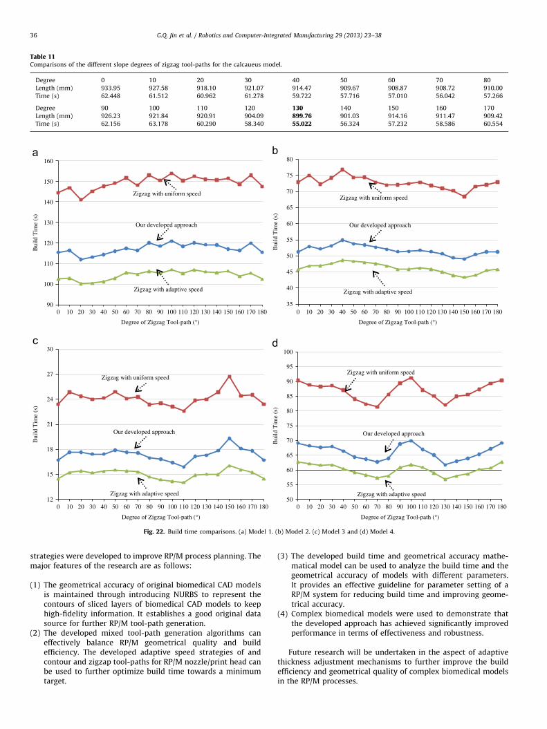
Table 11Comparisons of the different slope degrees of zigzag tool-paths for the calcaueus model.
Degree 0 10 20 30 40 50 60 70 80
Length (mm) 933.95 927.58 918.10 921.07 914.47 909.67 908.87 908.72 910.00
Time (s) 62.448 61.512 60.962 61.278 59.722 57.716 57.010 56.042 57.266
Degree 90 100 110 120 130 140 150 160 170
Length (mm) 926.23 921.84 920.91 904.09 899.76 901.03 914.16 911.47 909.42
Time (s) 62.156 63.178 60.290 58.340 55.022 56.324 57.232 58.586 60.554
90
100
110
120
130
140
150
160
0 10 20 30 40 50 60 70 80 90 100 110 120 130 140 150 160 170 18035
40
45
50
55
60
65
70
75
80
0 10 20 30 40 50 60 70 80 90 100 110 120 130 140 150 160 170 180
12
15
18
21
24
27
30
0 10 20 30 40 50 60 70 80 90 100 110 120 130 140 150 160 170 18050
55
60
65
70
75
80
85
90
95
100
0 10 20 30 40 50 60 70 80 90 100 110 120 130 140 150 160 170 180
Bui
ld T
ime
(s)
Degree of Zigzag Tool-path (°)
Bui
ld T
ime
(s)
Degree of Zigzag Tool-path (°)
Zigzag with uniform speed
Our developed approach
Zigzag with adaptive speed
Zigzag with uniform speed
Our developed approach
Zigzag with adaptive speed
Bui
ld T
ime
(s)
Degree of Zigzag Tool-path (°)
Zigzag with uniform speed
Our developed approach
Zigzag with adaptive speed
Bui
ld T
ime
(s)
Degree of Zigzag Tool-path (°)
Zigzag with uniform speed
Our developed approach
Zigzag with adaptive speed
Fig. 22. Build time comparisons. (a) Model 1. (b) Model 2. (c) Model 3 and (d) Model 4.
G.Q. Jin et al. / Robotics and Computer-Integrated Manufacturing 29 (2013) 23–3836
strategies were developed to improve RP/M process planning. Themajor features of the research are as follows:
(1)
The geometrical accuracy of original biomedical CAD modelsis maintained through introducing NURBS to represent thecontours of sliced layers of biomedical CAD models to keephigh-fidelity information. It establishes a good original datasource for further RP/M tool-path generation.(2)
The developed mixed tool-path generation algorithms caneffectively balance RP/M geometrical quality and buildefficiency. The developed adaptive speed strategies of andcontour and zigzap tool-paths for RP/M nozzle/print head canbe used to further optimize build time towards a minimumtarget.(3)
The developed build time and geometrical accuracy mathe-matical model can be used to analyze the build time and thegeometrical accuracy of models with different parameters.It provides an effective guideline for parameter setting of aRP/M system for reducing build time and improving geome-trical accuracy.(4)
Complex biomedical models were used to demonstrate thatthe developed approach has achieved significantly improvedperformance in terms of effectiveness and robustness.Future research will be undertaken in the aspect of adaptivethickness adjustment mechanisms to further improve the buildefficiency and geometrical quality of complex biomedical modelsin the RP/M processes.

88
90
92
94
96
98
100
0 0.1 0.3 0.5 0.7 0.9 1.1 1.3 1.5 1.7 1.988
90
92
94
96
98
100
0 0.1 0.3 0.5 0.7 0.9 1.1 1.3 1.5 1.7 1.9
86
88
90
92
94
96
98
100
0 0.1 0.3 0.5 0.7 0.9 1.1 1.3 1.5 1.7 1.988
90
92
94
96
98
100
0 0.1 0.3 0.5 0.7 0.9 1.1 1.3 1.5 1.7 1.9
Zigzag tool-paths
Geo
met
rica
l Acc
urac
y (%
)
Diameter of Nozzles/Print heads (mm)Diameter of Nozzles/Print heads (mm)
Geo
met
rica
l Acc
urac
y (%
) Our developed approach
Zigzag tool-paths
Our developed approach
Zigzag tool-pathsZigzag tool-paths
Our developed approach
Diameter of Nozzles/Print heads (mm)
Our developed approach
Geo
met
rica
l Acc
urac
y (%
)
Diameter of Nozzles/Print heads (mm)
Geo
met
rica
l Acc
urac
y (%
)
Fig. 23. Geometrical accuracy comparisons. (a) Model 1. (b) Model 2. (c) Model 3 and (d) Model 4.
G.Q. Jin et al. / Robotics and Computer-Integrated Manufacturing 29 (2013) 23–38 37
Acknowledgments
This research is partially supported by a collaborative grant ofthe State Key Laboratory of Digital Manufacturing Equipment andTechnology, Huazhong University of Science and Technology,China.
References
[1] Kruth JP, Levy G, Klocke F, Childs THC. Consolidation phenomena in laser andpowder-bed based layered manufacturing. Annals of CIRP 2007;56:730–759.
[2] Bourell DL, Leu MC, Rosen DW. Roadmap for additive manufacturing:identifying the future of freeform processing. The University of Texas atAustion, Austin, TX, USA; 2009.
[3] Sun W, Lal P. Recent development on computer aided tissue engineering—areview. Computer Methods and Programs in Biomedicine 2002;67:85–103.
[4] Marsan A, Dutta D. A survey of process planning techniques for layeredmanufacturing. In: Proceedings of the 1997 ASME design automation con-ference. Sacramento, CA, USA; 1997.
[5] Ding J, Colegrove P, Mehnen J, Ganguly S, Sequeira Almeida PM, Wang F, et al.Thermo-mechanical analysis of wire and arc additive layer manufacturingprocess on large multi-layer parts. Computational Materials Science2011;50(12):3315–3322.
[6] Allen S, Dutta D. Determination and evaluation of support structures inlayered manufacturing. Journal of Design and Manufacturing 1995;5:153–162.
[7] Sun SH, Chiang HW, Lee MI. Adaptive direct slicing of a commercial CADmodel for use in rapid prototyping. The International Journal of Advancedmanufacturing Technology 2007;34:689–701.
[8] Kulkarni P, Marsan A, Dutta A. A review of process planning techniques inlayered manufacturing. Rapid Prototyping Journal 2000;6(1):18–35.
[9] Misra D, Sundararajan V, Wright PK. Zig-zag tool path generation forsculptured surface finishing. Dimacs Series in Discrete Mathematics andTheoretical Computer Science 2005;67:265–280.
[10] Chang WR. CAD/CAM for the selective laser sintering process. MS thesis.University of Texas, Austin, USA, 1997.
[11] Yang Y, Loh HT, Fuh FYH, Wang YG. Equidistant path generation forimproving scanning efficiency in layered manufacturing. Rapid PrototypingJournal 2002;8(1):30–37.
[12] Genesan M, Fadel G. Hollowing rapid prototyping parts using offsettingtechniques. In: Proceedings of the 5th International conference on rapidprototyping; 1994. p. 241–51.
[13] Bertoldi M, Yardimci MA, Pistor CM, Guceri SI. Domain decomposition andspace filling curves in toolpath planning and generation. In: Proceedings ofthe 1998 solid freeform fabrication symposium; 1998. p. 267–74.
[14] Luo M, Zhang DH, Wu BH, Zhang Y. Optimisation of spiral tool path for five-axis milling of freeform surface blade. International Journal of Machining andMachinability of Materials 2010;8(3–4):266–282.
[15] Chiu WK, Yeung YC, Yu KM. Toolpath generation for layer manufacturing offractal objects. Rapid Prototyping Journal 2006;12(4):214–221.
[16] Nagy MS, Matyasi G. Analysis of STL files. Mathematical and ComputerModeling 2003;38:945–960.
[17] Wang CS, Chang TR. Re-triangulation in STL meshes for rapid prototyping andmanufacture. International Journal of Advanced Manufacturing Technology2008;37:770–781.
[18] Liu F, Zhou Li HD. Repair of STL errors. International Journal of ProductionResearch 2009;47(1):105–118.
[19] Chen X, Wang C, Ye X, Xiao Y, Huang S. Direct slicing from PowerSHAPEmodels for rapid prototyping. International Journal of Advanced Manufactur-ing Technology 2001;17:543–547.
[20] Shi Y, Chen X, Cai D, Huang S. Application software system based on directslicing for rapid prototyping. International Journal of Product Research2004;42:2227–2242.
[21] Cao W, Miyamoto Y. Direct slicing from AutoCAD solid models for rapidprototyping. International Journal of Advanced Manufacturing Technology2003;21:739–742.
[22] Ma W, But WC, He P. NURBS-based adaptive slicing for efficient rapidprototyping. Computer-Aided Design 2004;36:1309–1325.
[23] Starly B, Lau A, Sun W, Lau W, Bradbury T. Direct slicing of STEP based NURBSmodels for layered manufacturing. Computer-Aided Design 2005;37:387–397.
[24] Yin ZW. Direct integration of reverse engineering and rapid prototypingbased on the properties of NURBS or B-spline. Precision Engineering2004;28(3):293–301.
[25] Liu Z, Wang L, Lu B. Integrating cross-sectional imaging based reverse engineer-ing with rapid prototyping. Computers In Industry 2006;57:131–140.
[26] Chen CC, Sullivan PA. Predicting total build-time and the resultant cure depthof the 3D stereolithography process. Rapid Prototyping Journal 1996;2(4):27–40.

G.Q. Jin et al. / Robotics and Computer-Integrated Manufacturing 29 (2013) 23–3838
[27] Han W, Jafari MA, Seyed K. Process speeding up via deposition planning infused deposition-based layered manufacturing processes. Rapid PrototypingJournal 2003;9(4):212–218.
[28] Wah PK, Murty KG, Joneja A, Chiu LC. Toolpath optimization in layeredmanufacturing. IIE Transactions 2002;34(4):335–347.
[29] Castelino K, D’Souza R, Wright PK. Toolpath optimization for minimizingairtime during machining. Journal of Manufacturing Systems 1999;22(3):173–180.
[30] Liu W, Li L, Kochhar AK. A method for assessing geometrical errors in layeredmanufacturing. Part 1: Error interaction and transfer mechanisms. TheInternational Journal of Advanced Manufacturing Technology 1998;14(9):637–643.
[31] Liu W, Li L, Kochhar AK. A method for assessing geometrical errors in layeredmanufacturing. Part 2: mechanisms modeling and numerical evaluation. The
International Journal of Advanced Manufacturing Technology 1998;14(9):644–650.
[32] Bacchewar PB, Singhai SK, Pandey PM. Statistical modelling and optimizationof surface roughness in the selective laser sintering process. Proceedings ofthe Institution of Mechanical Engineers, Part B: Journal of EngineeringManufacture 2007;221(1):35–52.
[33] Armillotta A. Assessment of surface quality on textured FDM prototypes.Rapid Prototyping Journal 2006;12(1):35–41.
[34] Open CASCADE. /http://www.opencascade.org/S [accessed online 02.2012].[35] Ma YL, Hewitt WT. Point inversion and projection for NURBS curve and
surface: control polygon approach. Computer Aided Geometrical Design2003;20(2):79–99.
[36] Syed I. Feasibility study of key components and algorithm design for multi-material RP/M machine. Master dissertation, Coventry University, UK; 2011.