Embed Size (px)
Citation preview
Journal of Mechanical Engineering Vol. 16(1), 79-98, 2019
___________________
ISSN 1823- 5514, eISSN 2550-164X Received for review: 2017-04-07
© 2016 Faculty of Mechanical Engineering, Accepted for publication: 2018-12-26
Universiti Teknologi MARA (UiTM), Malaysia. Published: 2019-04-01
Parametric Study on Taper-ended Tubular Solid
Propellant Grains
Mahmoud Y. M. Ahmed
Aerospace Department, Military Technical College, Cairo, Egypt
ABSTRACT
The design of the solid propellant grain is a decisive aspect of the solid
propellant rocket motor performance. Tubular grain design is a favorable
design since it produces a high neutral (time-invariable) thrust-time profile.
However, neutrality of tubular grains deteriorates as the aspect ratio of the
grain deviates from an optimum value that is dependent on the web thickness.
In some cases, the undesirable phenomenon of erosive grain burning may take
place. One simple solution to restore neutrality is to add taper to the ends of
the grain. Loss of motor filling comes as penalty for adding these tapered ends.
The grain should thus be tailored to simultaneously satisfy both desired design
objectives namely, neutrality and filling. The present paper aims to address
the dependence of these two design objectives on the design of a taper-ended
tubular grain. The designs that are likely to yield erosive burning are also
addressed. A parametric study is conducted involving the aspect ratio of the
grain, its web thickness, and the taper angles on both ends. These parameters
were varied, respectively, in the ranges 0.5: 5, 0.1:0.9, and 10o:90o. It was
concluded that neutrality and filling of these grains are two competing
objectives. The maximum neutrality is achieved using a grain with aspect
ratios, web thickness, front and rear taper of 2:2.5, 0.1, 50o, and 30o,
respectively. In contrast, the maximum filling can be achieved using a grain
with aspect ratios and web thickness of 1:3.5 and 0.8, respectively, with no
taper at both ends. A compromised grain can have aspect ratio and web
thickness of 2 and 0.8, respectively, with no taper at both ends.
Keywords: Solid propellant rocket propulsion, grain design, neutrality, filling
coefficient, erosive burning.
Nomenclature
Ab Burning area, [m2]
Ab∗ Burning area-to-grain outer cross section area, [m2]
Din Inner diameter of propellant grain, [m]
Ahmed
80
Dout Outer diameter of propellant grain, [m]
KF Volumetric filling coefficient, [ ]
L Length of grain, [m]
Lout Outer length of the grain, [m]
Lin Length of inner cylindrical port of the grain, [m]
L∗ Length- to- diameter ratio , [ ]
y Instantaneous burnt distance, [m]
h Head-end taper angle, [deg.]
n Nozzle-end taper angle, [deg.]
τ Web thickness, [m]
𝜏∗ Web thickness-to-grain outer radius ratio, [ ]
Introduction
A rocket motor is an air-independent jet propulsion engine that carries both
fuel and oxidizer, the propellant, within itself. Depending on the physical state
of the used propellant, rocket motors are classified into rocket motors with
solid propellant (SPRM), liquid propellant (LPRM), hybrid propellant (HRM),
gel propellant, and cryogenic propellant. Of the two commonly used types,
SPRM have many advantages compared with LPRM. Solid propellant rocket
motors are simpler in design, easier in maintenance, safer in manipulation,
have higher reliability, and longer storage life.
In SPRM, the propellant to be burned is contained within the combustion
chamber. The solid propellant charge, the grain, contains all the chemical
elements necessary for complete burning. Once ignited, it usually burns
smoothly at a predetermined rate on all exposed surfaces of the grain. The
internal motor cavity grows as propellant is burned and consumed. the
resulting hot gas flows through the supersonic nozzle to impart thrust. Once
ignited, the motor combustion proceeds in an orderly manner until essentially
all the propellant has been consumed.
Thrust magnitude control is one of potential requirements addressed in some
rocket applications. While in LPRM the flow can be modified during flight, it
is unmanageable to modify the thrust of SPRM once ignited. To solve this
problem in SPRM, tailoring some parameters during the design phase would
permit a reasonable predictable thrust history. The desired thrust history
(profile) can be achieved via tuning the grain geometry, inhibiting some
surfaces, and using different propellant compositions. Generally, the thrust
profile of an SPRM can be classified according to its temporal behavior into
progressive, regressive, neutral, and dual thrust profiles [1-2]. In neutral
profile, the chamber pressure, and hence, the thrust remain approximately
constant with time, typically within about +15%. In progressive profile, thrust
increases monotonically with time whereas in regressive profile, the thrust
decreases monotonically with time. In dual profile, the SPRM yields two
Parametric Study on Taper-ended Tubular Solid Propellant Grains
81
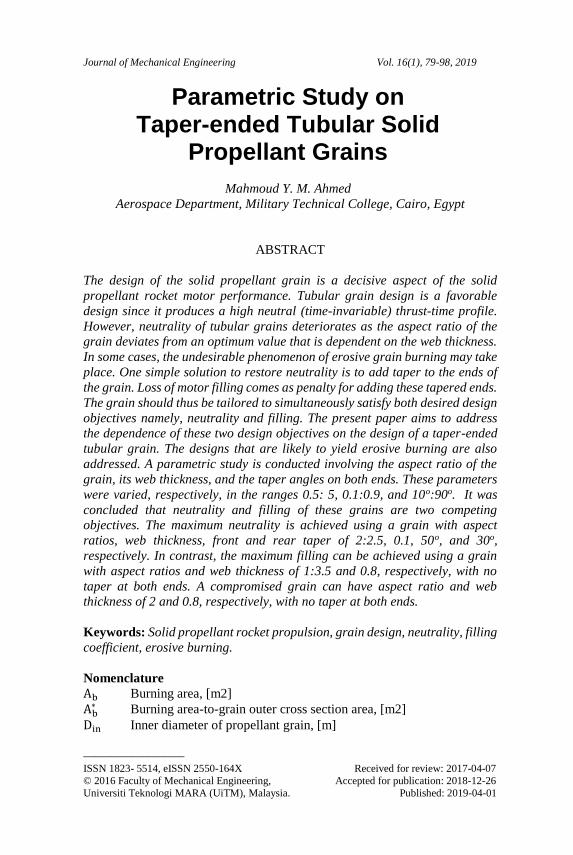
distinct levels of thrust; a high (boost) level followed sharply by a low (sustain)
level. Figure 1 compares the possible thrst profiles of solid propellant rocket
motors.
Figure 1: Possible thrst profiles of solid propellant rocket motors
In almost all applications, neutral, single or dual, thrust profiles are desired
since they yield the cruise (constant speed) flight preferred for proper flight
control especially for guided rockets. A neutral burning is attained using
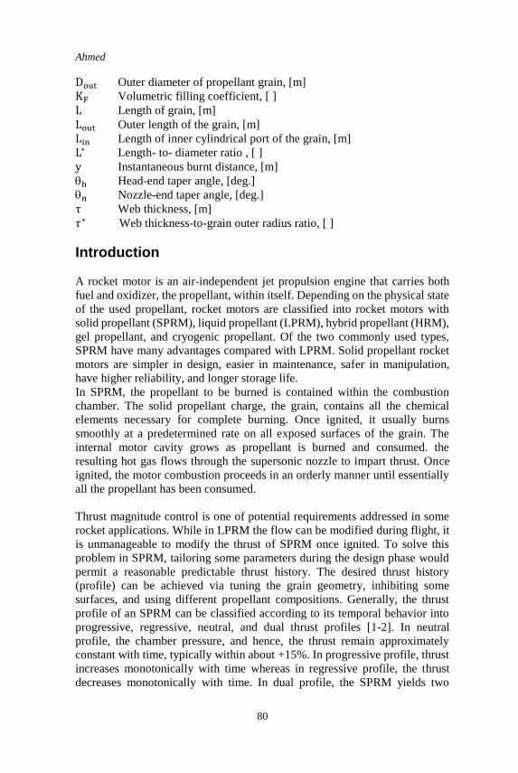
various grain geometries and inhibition styles. The simplest neutral burning
grain configuration is the end-burning (cigarette) grain, Fig. 2.a. This
configuration also achieves the maximum filling (packing) of the motor cavity.
However, the thrust level of the end-burning grains is low due to the small
burning area. In contrast, a neutral burning with a high thrust level can be
achieved using side (tubular) burning grains, Fig. 2.b. This comes with the
penalties of having a short operation time and a low motor filling. The filling
of such design can be increased by reducing the inner and outer port areas.
However, if the port areas are too small, the gas flow speed along the grain
may reach values high enough to cause erosive burning; a phenomenon that
produces an undesired progressive burning and yields a large amount of sliver
(propellant waste residuals). A compromise between the neutrality and filling
can to a great extent be attained using internal burning (perforated) grains, Fig.
2.c. If the perforation along the grain is properly designed, a nearly neutral
burning can be achieved. Typical perforation designs are illustrated in Fig. 2.d
[1,2]. Clearly, the level of motor packing (filling) varies from one perforation
design to another however, the main drawback of such grain design is the
complexity of design and production in addition to the possibility of erosive
burning in some designs.
Ahmed
82
(a) (b)
(c) (d)
(e) (f)
Figure 2: Typical solid propellant grain designs
One simple design that can achieve a neutral burning as well as high motor
filling is the end-tubular burning grain. This grain is inhibited from the outer
peripheral surface only and is allowed to burn from all other surfaces, Fig. 2.e.
If the dimensions of the grain are properly set, a neutral burning can be
achieved. Neutrality may deteriorate for longer grains of this type. Adding
tapering to grain ends (Fig. 2.f) was found to restore neutrality however, loss
in filling emerged as a penalty [3].
Understanding the regression behaviour of solid propellant grains has drawn
the efforts of researchers over the years to the extent that recent studies discuss
the design optimization of these grains. For instance, design of star perforated
grains was discussed by Karman et al. [4], Brooks [5], Krishnan [6] and
Albarado et al. [7]. The designs of finocyl grains, tubular grains with radial
slots, and wagon-wheel grains were examined by Nisar et al. [8], Kamran and
Guozhu [9], and Raza and Liang [10-12], respectively.
Desipte its design simplicity compated with perforated grains, taper-ended
tubular grains have drawn the least attention of researchers. Since their
introduction as a patent in 1961 by Kirchner [13], almost no work was reported
on these grains in the open literature. Shekhar [14] examined the neutrality of
Wagon wheel-perforated
Star-perforated
Parametric Study on Taper-ended Tubular Solid Propellant Grains
83
tubular grains with one tapered end. He developed mathematical expressions
for the area of the burning surface and investigated the effects of varying the
grain length, web thickness, and taper angle. Noaman et al. [3] examined
neutrality and filling of the tubular grain tapered at both ends for web thickness
of 0.4 and three values of taper angles (equal in both sides).
Neutrality and filling of these taper-ended tubular grains are believed to be
dependent on the their configuration. The present work is intended to conduct
a parametric study on the dependence of neutrality and filling of such grains
on their design. Mathematical expressions for these two merits are derived in
terms of the grain design parameters and are applied for a large number of
distinct designs that are generated using a space-filling sampling approach.
The present work can be viewed as an extension for the work of Noaman et al.
[3] with web thickness varied, unequal taper angles on both ends, and the entire
design space is expanded. In addition, along with neutrality and filling, erosive
burning that may take place for some designs is taken into consideration. This
likelihood is addressed for specific ballistic environment. The maximum
combustion gas flow velocity along the grain is taken as a measure of erosive
burning occurrence. The remainder of the paper is organized as follows. The
sampling methodology is presented next along with the full derivations for
neutrality, filling, and erosive burning measure. The following section presents
and discusses the main findings of the study. The paper finalizes with main
conclusions of the study.
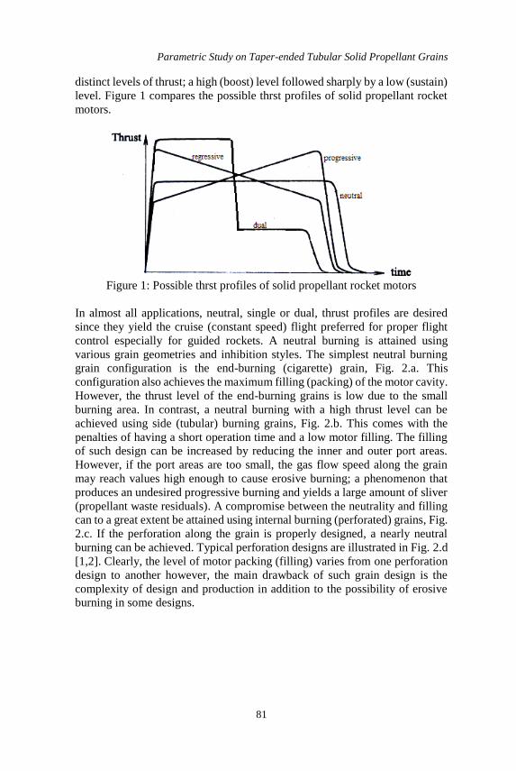
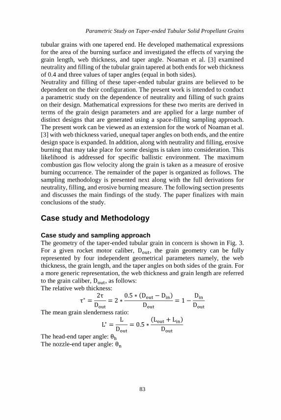
Case study and Methodology Case study and sampling approach The geometry of the taper-ended tubular grain in concern is shown in Fig. 3.
For a given rocket motor caliber, Dout, the grain geometry can be fully
represented by four independent geometrical parameters namely, the web
thickness, the grain length, and the taper angles on both sides of the grain. For
a more generic representation, the web thickness and grain length are referred
to the grain caliber, Dout, as follows:
The relative web thickness:
τ∗ =2τ
Dout
= 2 ∗0.5 ∗ (Dout − Din)
Dout
= 1 −Din
Dout
The mean grain slenderness ratio:
L∗ =L
Dout
= 0.5 ∗(Lout + Lin)
Dout
The head-end taper angle: θh
The nozzle-end taper angle: θn
Ahmed
84
Figure 3: Configuration and design parameters of taper-ended tubular grains
By independently varying these four parameters within some upper and lower
respective bounds, various distinct designs can be generated. In this work, the
lower and upper bounds of variation for these four parameters are listed in
Table 1.
Table 1: Lower and upper bounds of grain design parameters Design parameter Lower bound Upper bound
Relative web thickness, τ∗ 0.1 0.9
Mean grain slenderness ratio, L∗ 0.5 5
Head-end taper angle, θh 10o 90o
Nozzle-end taper angle, θn 10o 90o
Samples are selected from the developed four-dimensional design space using
the full-factorial sampling technique. With 9, 10, 9 and 9 divisions for τ∗, L∗,
θh, and θn, respectively, a total of 7290 samples (each representing a distinct
grain design) is generated. For each design, the neutrality, filling, and erosive
burning criterion is calculated using the formula derived below.
Neutrality Coefficient Neutrality of burning is express how the produced thrust maintains a constant
value over the motor operation time. For solid propellant grains, neutrality is
achieved if the area of burning surface maintains a nearly constant value over
the entire operation time. There are many measures of neutrality; here, the ratio
between the maximum and average burning surface areas of the grain is taken
as a measure of neutrality. Following this definition, neutrality coefficient is
generally greater than 1 and the best neutrality value is 1 which indicates that
the maximum burning surface area is equal to the average burning surface area.
In what follows, this expression for neutrality is derived under the following
two assumptions:
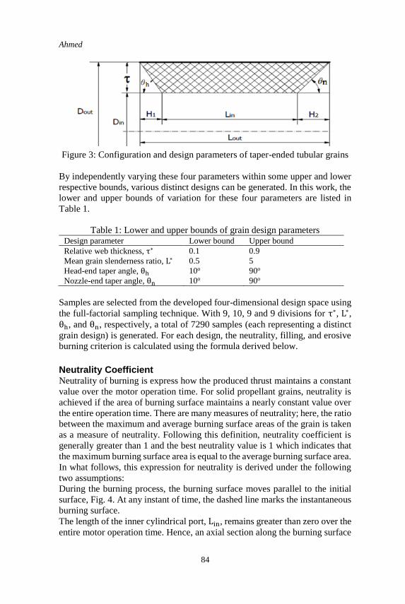
During the burning process, the burning surface moves parallel to the initial
surface, Fig. 4. At any instant of time, the dashed line marks the instantaneous
burning surface.
The length of the inner cylindrical port, Lin, remains greater than zero over the
entire motor operation time. Hence, an axial section along the burning surface
Parametric Study on Taper-ended Tubular Solid Propellant Grains
85
will retain a trapezoidal rather than a triangular shape over the entire burning
time. This implies that the grain dimensions are such that it is consumed axially
from both sides before the inner cylindrical surface reaches the outer one. Out
of the 7290 samples generated in the design space presented above, 551
samples violate this condition and are eliminated from the samples.
Figure 4: Regression style of the grain
Following the above assumptions, for a given burnt distance, y, the burning
area can be expressed as:
Ab = π(Din + 2y) [Lin − y (tan (θh
2) + tan (
θn
2))]
+π
2(Dout + Din + 2y) [(
− y
sin (θh)) + (
− y
sin (θn))]
(1)
Substituting in the above equation for the following geometric relations:
Lin = L −H1
2−
H2
2,
(H1 and H2 are the front and rear taper lengths; shown in Fig. 3)
tan (θ
2) =
1
sin (θ)−
1
tan (θ)
H1 =
tan (θh) H2 =
tan (θn)
Din = Dout − 2
Equation (1) will have the form:
Ahmed
86
Ab = π [L(D − 2) −2yD
sin(θh)−
2yD
sin(θn)+
3y
sin(θh)+
3y
sin(θn)
+yD
tan(θh)+
yD
tan(θn)−
3y
tan(θh)−
3y
tan(θn)+ 2yL
−3y2
sin(θh)−
3y2
sin(θn)+
2y2
tan(θh)+
2y2
tan(θn)
−τD
2 tan(θh)−
τD
2 tan(θn)+
τ2
tan(θh)+
τ2
tan( θn)
+τD
sin(θh)−
τ2
sin(θh)−
τ2
sin(θn)+
τy
sin(θh)
+τy
sin(θn)]
(2)
Now, introducing the following dimensionless terms:
Ab∗ =
Abπ
4Dout
2 ∗ =
2τ
Dout
y∗ =y
τ L∗ =
L
Dout
Eventually, Eqn. (2) will have the form:
Ab∗ = a + by∗ + cy∗2
where:
a = 4L∗ − 4∗L∗ −τ∗
tan(θh)−
τ∗
tan(θn)+
τ∗2
tan(θh)+
τ∗2
tan(θn)+
2τ∗
sin(θh)
+2τ∗
sin(θn)−
τ∗2
sin(θh)−
τ∗2
sin(θn)
b = −4τ∗
sin(θh)−
4τ∗
sin(θn)+
4τ∗2
sin(θh)+
4τ∗2
sin(θn)+
2τ∗
tan(θh)+
2τ∗
tan(θn)
−3τ∗2
tan(θh)−
3τ∗2
tan(θn)+ 4τ∗L∗
c = −3τ∗2
sin(θh)−
3τ∗2
sin(θn)+
2τ∗2
tan(θh)+
2τ∗2
tan(θn)
Finally, neutrality is defined as the ratio of the maximum to the average
burning surfaces encountered during the burning duration, i.e.,:
N = (Ab∗ )max (Ab
∗ )average⁄ (4)
where:
(Ab∗ )max = a −
b2
4c (Ab
∗ )average = a + b
2 +
c
3
Filling Coefficient
Parametric Study on Taper-ended Tubular Solid Propellant Grains
87
The filling reflects the level of packing of propellant inside the rocket motor.
Here, the coefficient of volumetric filling is implemented to describe the level
of filling. It is defined as the ratio of the grain volume to the available empty
motor volume. These two volumes are expressed, respectively, as:
VP =π
4(Dout
2 − Din2 )L =
π
4[Dout
2 − (Dout − 2τ)2]L =π
4L(4Doutτ − 4τ2)
Vm =π
4LoutDout
2 =π
4(L +
H1
2+
H2
2) Dout
2
=π
4[L +
τ
2 tan(θh)+
τ
2tan (θn)] Dout
2
Hence, the volumetric filling coefficient is expressed as:
KF = VP
Vm
= [1
1 + (τ
2L) (
1
tan(θh)+
1
tan(θn))
] [4τDout − 4τ2
Dout2 ]
= (2τ∗ − τ∗2) [1
1 + (τ∗
4L∗) (1
tan(θh)+
1
tan(θn))
]
(5)
The volumetric filling coefficient has a theoretical maximum value of 1; a
value of this coefficient closer to 1 is better.
Erosive burning Erosive burning is defined as the augmentation of grain burning rate due to
excessive gas flow speed along the grain port [1, 2]. Clearly, erosive burning
is undesirable since it yields unpredictable thrust profiles as well as
considerable amount of sliver. As a rule of thumb, if the velocity of combustion
gases through the port reaches 200 m/s, erosive burning occurs. For the grain
configuration considered in this study, erosive burning can take place in some
designs and it is desired to determine these designs. To do so, the maximum
combustion gas velocity is estimated. It is the gas velocity at the nozzle-end of
inner cylindrical port of the grain immediately at the onset of combustion
calculated as:
AP =π
4Din
2 =π
4(Dout − 2τ)2
The gases flowing through this area are generated as a result of combustion of
all upstream burning surfaces calculated as:
Ahmed
88
Ag = πDinLin +π
2(Din + Dout) [
τ
sin (θh)]
= π(Dout − 2τ) (L −
tan (θh)−
tan (θn))
+π
2(2Dout − 2τ) [
τ
sin (θh)]
Dividing Ag by AP,
Ag
AP
=
4 (L −1
2(
τ
tan(θh)+
τ
tan(θn)))
Dout − 2τ+ (1 +
Dout
Dout − 2τ) (
τ
(Dout − 2)sin (θh))
Dividing both nominator and denominator by π
4Dout
2,
Ag
AP
=4
(1 − τ∗)[L∗ −
1
2(
τ∗
tan(θh)+
τ∗
tan(θn))]
+ (1 +1
1 − τ∗) [
τ∗
(1 − τ∗)sin (θh)]
(6)
Based on continuity principle, the mass flow rate of combustion gases through
any given port is equal to their rate of generation from all upstream surfaces
[3]. Hence:
VgAPρg = Agρspr or: Vg =Ag
AP
ρsp
ρg
r
where Ag AP⁄ is defined in Eqn. (6) and ρsp and ρg are the densities of the solid
propellant and combustion gas products, respectively. r is the rate of burning
of the propellant that is dependent on the combustion pressure through the
burning law relation [1, 2]. For any design, if Vg exceeds the value of 200 m/s,
erosive burning takes place causing the undesirable excessive regression
pattern. Clearly, estimating the erosive burning requires specifying the ballistic
properties of the used propellant. Here, the properties of a typical double-base
propellant listed in the table below are used.
Table 2: Ballistic properties of the used propellant for erosive burning
calculations
Ballistic property Value
Combustion pressure, Pc [bar] 70
Burning law r = 0.713 × 10⁻⁵P0.569
Burning rate at Pc, [m/s] 0.008
Propellant density, ρsp, [Kg/m3] 1563
Combustion gas density, ρg, [Kg/m3] 6.05
Results and Discussions
Parametric Study on Taper-ended Tubular Solid Propellant Grains
89
Samples distribution in the objective space Figure 5a below shows the distribution of all samples in the two-dimensional
objective space with neutrality and filling as the space coordinates. Here, only
the 6738 samples that obey the constraints for inner cylinder length are plotted.
The solid markers refer to the samples that encounter erosive burning based on
the ballistic conditions proposed in the previous section. The hollow markers
refer to the samples that are expected to experience no erosive burning. A
zoom-in at the Pareto front (the set of competing designs) of all samples is
illustrated in Fig. 5b whereas Fig. 5c shows the Pareto front of all samples with
no erosive burning.
It is clear that the two objectives namely, maximum filling and minimum
neutrality are competing. A single sample that possesses both maximum filling
and minimum (best) neutrality does not exist. As the filling coefficient values
of the samples approach the maximum value of 1, the corresponding neutrality
coefficient values shift further higher than the minimum value of 1. In addition,
samples that have the upper values of filling; samples with filling higher than
0.96 always encounter erosive burning.
(a)
0.1
0.2
0.3
0.4
0.5
0.6
0.7
0.8
0.9
1
0.75 1.25 1.75 2.25 2.75 3.25 3.75 4.25 4.75 5.25 5.75 6.25
Filli
ng
coe
ffic
ien
t, K
f
Neutrality coefficient, N
erosive burning
no erosive burning
Ahmed
90
(b)
(c)
Figure 5: Distribution of samples in the objective space
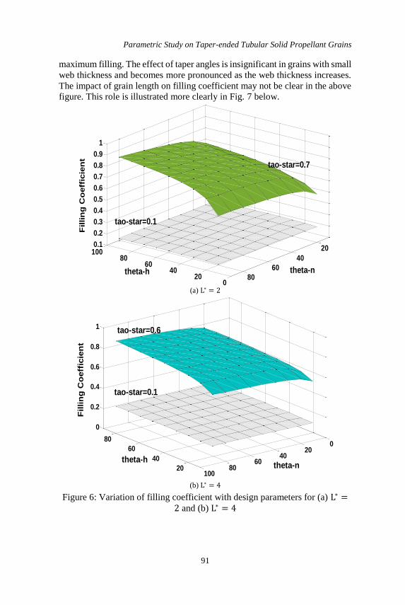
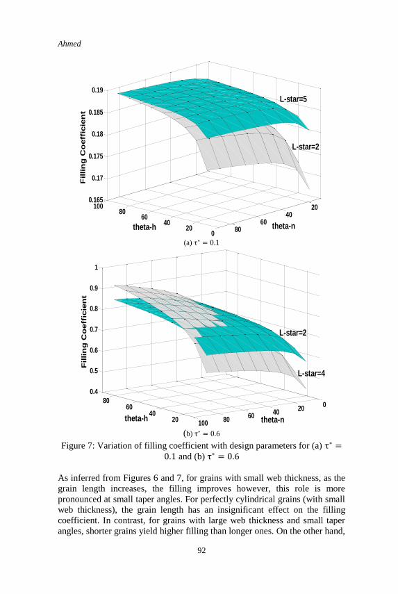
Variation of filling coefficient with the design parameters Figure 6 illustrates samples of the variation of filling coefficient with the grain
design parameters. Examining the above figures reveals the following. Grain
filling coefficient increases with the increase in web thickness for all grain
lengths. For a given web thickness, as the taper angles on both ends increases,
the filling increases; perfectly cylindrical grains (with no taper ends) yield the
0.7
0.75
0.8
0.85
0.9
0.95
1
1 1.05 1.1 1.15 1.2 1.25 1.3
Filli
ng
coe
ffic
ien
t, K
f
Neutrality coefficient, N
erosive burning
no erosive burning
0.7
0.75
0.8
0.85
0.9
0.95
1
1 1.05 1.1 1.15 1.2 1.25 1.3
Filli
ng
coe
ffic
ien
t, K
f
Neutrality coefficient, N
Pareto
front
Pareto
front
Parametric Study on Taper-ended Tubular Solid Propellant Grains
91
maximum filling. The effect of taper angles is insignificant in grains with small
web thickness and becomes more pronounced as the web thickness increases.
The impact of grain length on filling coefficient may not be clear in the above
figure. This role is illustrated more clearly in Fig. 7 below.
(a) L∗ = 2
(b) L∗ = 4
Figure 6: Variation of filling coefficient with design parameters for (a) L∗ =2 and (b) L∗ = 4
020
4060
80100
20
40
60
80
0.1
0.2
0.3
0.4
0.5
0.6
0.7
0.8
0.9
1
Fillin
g C
oeff
icie
nt
tao-star=0.1
theta-h
tao-star=0.7
theta-n
20
40
60
800
2040
6080
100
0
0.2
0.4
0.6
0.8
1
Fillin
g C
oeff
icie
nt
tao-star=0.1
theta-ntheta-h
tao-star=0.6
Ahmed
92
(a) τ∗ = 0.1
(b) τ∗ = 0.6
Figure 7: Variation of filling coefficient with design parameters for (a) τ∗ =0.1 and (b) τ∗ = 0.6
As inferred from Figures 6 and 7, for grains with small web thickness, as the
grain length increases, the filling improves however, this role is more
pronounced at small taper angles. For perfectly cylindrical grains (with small
web thickness), the grain length has an insignificant effect on the filling
coefficient. In contrast, for grains with large web thickness and small taper
angles, shorter grains yield higher filling than longer ones. On the other hand,
020
4060
80100 20
4060
80
0.165
0.17
0.175
0.18
0.185
0.19F
illin
g C
oeff
icie
nt
theta-h theta-n
L-star=5
L-star=2
2040
6080
020
4060
80100
0.4
0.5
0.6
0.7
0.8
0.9
1
Fillin
g C
oeff
icie
nt
theta-ntheta-h
L-star=4
L-star=2
Parametric Study on Taper-ended Tubular Solid Propellant Grains
93
a higher filling can be achieved with large web thickness and high taper angles
if longer grains are used.
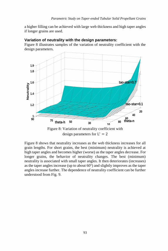
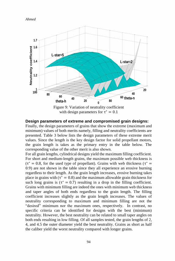
Variation of neutrality with the design parameters: Figure 8 illustrates samples of the variation of neutrality coefficient with the
design parameters.
Figure 8: Variation of neutrality coefficient with
design parameters for L∗ = 2
Figure 8 shows that neutrality increases as the web thickness increases for all
grain lengths. For short grains, the best (minimum) neutrality is achieved at
high taper angles and becomes higher (worse) as the taper angles decrease. For
longer grains, the behavior of neutrality changes. The best (minimum)
neutrality is associated with small taper angles. It then deteriorates (increases)
as the taper angles increase (up to about 60o) and slightly improves as the taper
angles increase further. The dependence of neutrality coefficient can be further
understood from Fig. 9.
1030507090
2040
6080
1
1.2
1.4
1.6
1.8
1.9
Neu
trality
theta-h
tao-star=0.1
tao-star=0.7
theta-n
Ahmed
94
Figure 9: Variation of neutrality coefficient
with design parameters for τ∗ = 0.1
Design parameters of extreme and compromised grain designs: Finally, the design parameters of grains that show the extreme (maximum and
minimum) values of both merits namely, filling and neutrality coefficients are
presented. Table 3 below lists the design parameters of these extreme merit
values. Since the length is the key design factor for solid propellant motors,
the grain length is takes as the primary entry in the table below. The
corresponding value of the other merit is also shown.
For all grain lengths, cylindrical designs yield the maximum filling coefficient.
For short and medium-length grains, the maximum possible web thickness is
(τ∗ = 0.8, for the used type of propellant). Grains with web thickness (τ∗ =0.9) are not shown in the table since they all experience an erosive burning
regardless to their length. As the grain length increases, erosive burning takes
place in grains with (τ∗ = 0.8) and the maximum allowable grain thickness for
such long grains is (τ∗ = 0.7) resulting in a drop in the filling coefficient.
Grains with minimum filling are indeed the ones with minimum web thickness
and taper angles of both ends regardless to the grain length. The filling
coefficient increases slightly as the grain length increases. The values of
neutrality corresponding to maximum and minimum filling are not the
“desired” minimum nor the maximum ones, respectively. In contrast, no
specific criteria can be identified for designs with the best (minimum)
neutrality. However, the best neutrality can be related to small taper angles on
both ends resulting in low filling. Of all samples tested, the grain lengths of 2,
4, and 4.5 the outer diameter yield the best neutrality. Grains as short as half
the caliber yield the worst neutrality compared with longer grains.
020
4060
80100
2040
6080
1
1.2
1.4
1.6
1.7
Neu
trality
co
eff
icie
nt
L-star=5
theta-ntheta-h
L-star=2
Parametric Study on Taper-ended Tubular Solid Propellant Grains
95
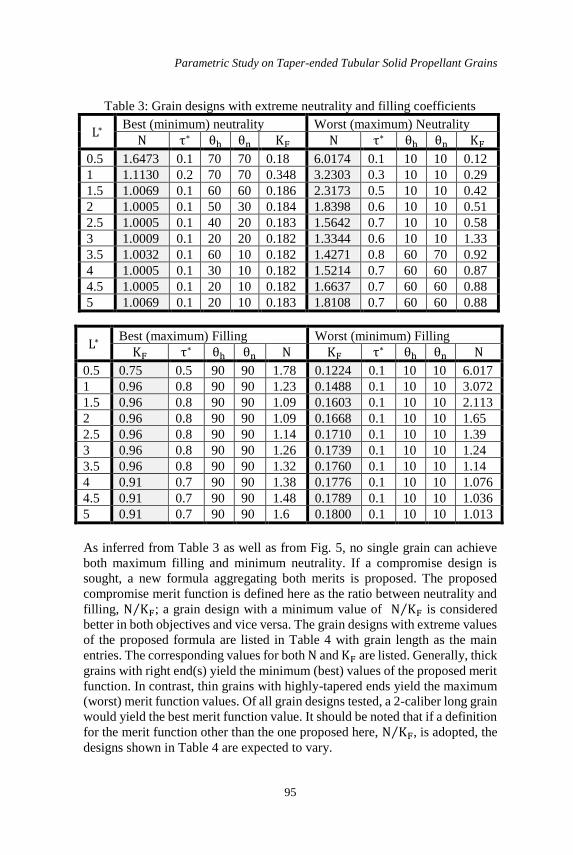
Table 3: Grain designs with extreme neutrality and filling coefficients
Worst (maximum) Neutrality Best (minimum) neutrality L∗
KF θn θh τ∗ N KF θn θh τ∗ N
0.12 10 10 0.1 6.0174 0.18 70 70 0.1 1.6473 0.5
0.29 10 10 0.3 3.2303 0.348 70 70 0.2 1.1130 1
0.42 10 10 0.5 2.3173 0.186 60 60 0.1 1.0069 1.5
0.51 10 10 0.6 1.8398 0.184 30 50 0.1 1.0005 2
0.58 10 10 0.7 1.5642 0.183 20 40 0.1 1.0005 2.5
1.33 10 10 0.6 1.3344 0.182 20 20 0.1 1.0009 3
0.92 70 60 0.8 1.4271 0.182 10 60 0.1 1.0032 3.5
0.87 60 60 0.7 1.5214 0.182 10 30 0.1 1.0005 4
0.88 60 60 0.7 1.6637 0.182 10 20 0.1 1.0005 4.5
0.88 60 60 0.7 1.8108 0.183 10 20 0.1 1.0069 5
Worst (minimum) Filling Best (maximum) Filling L∗
N θn θh τ∗ KF N θn θh τ∗ KF
6.017 10 10 0.1 0.1224 1.78 90 90 0.5 0.75 0.5
3.072 10 10 0.1 0.1488 1.23 90 90 0.8 0.96 1
2.113 10 10 0.1 0.1603 1.09 90 90 0.8 0.96 1.5
1.65 10 10 0.1 0.1668 1.09 90 90 0.8 0.96 2
1.39 10 10 0.1 0.1710 1.14 90 90 0.8 0.96 2.5
1.24 10 10 0.1 0.1739 1.26 90 90 0.8 0.96 3
1.14 10 10 0.1 0.1760 1.32 90 90 0.8 0.96 3.5
1.076 10 10 0.1 0.1776 1.38 90 90 0.7 0.91 4
1.036 10 10 0.1 0.1789 1.48 90 90 0.7 0.91 4.5
1.013 10 10 0.1 0.1800 1.6 90 90 0.7 0.91 5
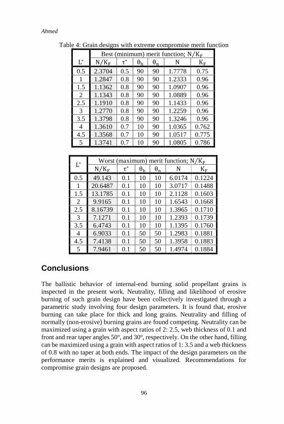
As inferred from Table 3 as well as from Fig. 5, no single grain can achieve
both maximum filling and minimum neutrality. If a compromise design is
sought, a new formula aggregating both merits is proposed. The proposed
compromise merit function is defined here as the ratio between neutrality and
filling, N KF⁄ ; a grain design with a minimum value of N KF⁄ is considered
better in both objectives and vice versa. The grain designs with extreme values
of the proposed formula are listed in Table 4 with grain length as the main
entries. The corresponding values for both N and KF are listed. Generally, thick
grains with right end(s) yield the minimum (best) values of the proposed merit
function. In contrast, thin grains with highly-tapered ends yield the maximum
(worst) merit function values. Of all grain designs tested, a 2-caliber long grain
would yield the best merit function value. It should be noted that if a definition
for the merit function other than the one proposed here, N KF⁄ , is adopted, the
designs shown in Table 4 are expected to vary.
Ahmed
96
Table 4: Grain designs with extreme compromise merit function
Best (minimum) merit function; N KF⁄
L∗ KF N θn θh τ∗ N KF⁄
0.75 1.7778 90 90 0.5 2.3704 0.5
0.96 1.2333 90 90 0.8 1.2847 1
0.96 1.0907 90 90 0.8 1.1362 1.5
0.96 1.0889 90 90 0.8 1.1343 2
0.96 1.1433 90 90 0.8 1.1910 2.5
0.96 1.2259 90 90 0.8 1.2770 3
0.96 1.3246 90 90 0.8 1.3798 3.5
0.762 1.0365 90 10 0.7 1.3610 4
0.775 1.0517 90 10 0.7 1.3568 4.5
0.786 1.0805 90 10 0.7 1.3741 5
Worst (maximum) merit function; N KF⁄ L∗
KF N θn θh τ∗ N KF⁄
0.1224 6.0174 10 10 0.1 49.143 0.5
0.1488 3.0717 10 10 0.1 20.6487 1
0.1603 2.1128 10 10 0.1 13.1785 1.5
0.1668 1.6543 10 10 0.1 9.9165 2
0.1710 1.3965 10 10 0.1 8.16739 2.5
0.1739 1.2393 10 10 0.1 7.1271 3
0.1760 1.1395 10 10 0.1 6.4743 3.5
0.1881 1.2983 50 50 0.1 6.9033 4
0.1883 1.3958 50 50 0.1 7.4138 4.5
0.1884 1.4974 50 50 0.1 7.9461 5
Conclusions
The ballistic behavior of internal-end burning solid propellant grains is
inspected in the present work. Neutrality, filling and likelihood of erosive
burning of such grain design have been collectively investigated through a
parametric study involving four design parameters. It is found that, erosive
burning can take place for thick and long grains. Neutrality and filling of
normally (non-erosive) burning grains are found competing. Neutrality can be
maximized using a grain with aspect ratios of 2: 2.5, web thickness of 0.1 and
front and rear taper angles 50o, and 30o, respectively. On the other hand, filling
can be maximized using a grain with aspect ratios of 1: 3.5 and a web thickness
of 0.8 with no taper at both ends. The impact of the design parameters on the
performance merits is explained and visualized. Recommendations for
compromise grain designs are proposed.
Parametric Study on Taper-ended Tubular Solid Propellant Grains
97
A compromised grain can have aspect ratio and web thickness of 2 and 0.8,
respectively, with no taper at both ends.
References
[1] Sutton, G. P., "Rocket Propulsion element," Seventh edition, John
Wiley,1992.
[2] Barrere, M., Jaumotte, A., De veubeke, B. F. and Vandenkerckhove, J.,"
Rocket Propulsion," Elsevier publishing company, 1960.
[3] Noaman, H. R., Ahmed, M. Y., Abdalla, H. M. and Al-Sanabawy, M.
A., “Neutrality of Taper-Ended Tubular Grains,” 15th International
Conference on Aerospace Sciences and Aviation Technology, ASAT –
15, May 28 - 30, 2013.
[4] A. Kamran, L. Guozhu, A. F. Rafique, S. Naz, and Q. Zeeshan, "Star
Grain Optimization using Genetic Algorithm," in 51st
AIAA/ASME/ASCE/AHS/ASC Structures, Structural Dynamics, and
Materials Conference 18th AIAA/ASME/AHS Adaptive Structures
Conference 12th, 2010, p. 3084.
[5] W. T. Brooks, "Ballistic optimization of the star grain configuration,"
Journal of spacecraft and rockets, vol. 19, pp. 54-59, 1980.
[6] S. Krishnan, “Design of Neutral Burning Star Grains,” Journal of
Spacecraft and Rockets, 1975, Vol. 12, No. 1, pp. 60-72.
[7] K. Albarado, R. Hartfield, W. Hurston, and R. Jenkins, “Solid Rocket
Motor Design Using Hybrid Optimization” International Journal of
Aerospace Engineering, Volume 2012, Article ID 987402.
[8] K. Nisar, L. Guozhu, and Q. Zeeshan, "A hybrid Optimization Approach
for SRM Finocyl Grain Design," Chinese Journal of Aeronautics, Vol.
21, pp. 481-487, 2008.
[9] A. Kamran and L. Guozhu, "Design and Optimization of 3D Radial Slot
Grain Configuration," Chinese Journal of Aeronautics, Vol. 23, pp. 409-
414, 2010.
[10] M. A. Raza and W. Liang, "Design and Optimization of 3D Wagon
Wheel Grain for Dual Thrust Solid Rocket Motors," Propellants,
Explosives, Pyrotechnics, vol. 38, pp. 67-74, 2013.
[11] M. A. Raza and W. Liang, "Robust performance optimization of dual
thrust rocket motor," Aircraft Engineering and Aerospace Technology,
vol. 84, pp. 244-251, 2012.
[12] M. A. Raza and W. Liang, "Robust Design Optimization of 3D Tandem
Grain Configuration for Dual Thrust Solid Rocket Motor," Proceedings
of the 2010 NDIA Conference.
[13] W. R. Kirchner, Tapered Tubular Propellant Grain, U.S. Patent No.
3000317, Sept. 19, 1961
[14] Himanshu Shekhar, Design of Funnel Port Tubular Propellant Grain for
Neutral Burning Profile in Rockets, Defence Science Journal, Vol. 59,
No. 5, September 2009, pp. 494-498


![[XLS] · Web view79 0 79 79000 79 79332 79 79085 79 79005 79 10051 79 79328 79 79148 79 10061 79 79476 79 79971 79 79045 79 79772 79 79301 79 79333 79 79154 79 10018 79 79101 79 79335](https://img.pdfslide.us/doc/110x75/5adf13517f8b9a6e5c8bad58/xls-view79-0-79-79000-79-79332-79-79085-79-79005-79-10051-79-79328-79-79148-79.jpg)


![Accu Chek Reference Guide Blood Glucose Monitor 98 79 EC 3969[1]](https://img.pdfslide.us/doc/110x75/577d26351a28ab4e1ea08b0c/accu-chek-reference-guide-blood-glucose-monitor-98-79-ec-39691.jpg)