Embed Size (px)
Citation preview

Journal ofMaterials Chemistry A
PAPER
Publ
ishe
d on
11
Sept
embe
r 20
14. D
ownl
oade
d by
Uni
vers
ity o
f T
enne
ssee
at K
noxv
ille
on 1
0/06
/201
6 21
:32:
32.
View Article OnlineView Journal | View Issue
Synthesis of LiAl2
aCollege of Environmental Science and Eng
Qinghua East Road, Haidian District, Beij
[email protected]; [email protected] Composites Laboratory, Dan F Sm
Lamar University, Beaumont, TX 77710, UScKey Laboratory of Photochemical Conversio
Institute of Physics and Chemistry, Chinese A
ChinadChemistry Research Laboratory, Departm
Manseld Road, Oxford, OX1 3TA, UK
Cite this: J. Mater. Chem. A, 2014, 2,18454
Received 7th August 2014Accepted 11th September 2014
DOI: 10.1039/c4ta04065a
www.rsc.org/MaterialsA
18454 | J. Mater. Chem. A, 2014, 2, 18
-layered double hydroxides forCO2 capture over a wide temperature range
Liang Huang,a Junya Wang,a Yanshan Gao,a Yaqian Qiao,a Qianwen Zheng,a
Zhanhu Guo,b Yufei Zhao,c Dermot O'Hared and Qiang Wang*a
Although there are many reports on layered double hydroxide (LDH) derived CO2 adsorbents, none of them
have studied the special case of LiAl2 LDHs. Here we report the first detailed investigation of the
performance of LiAl2 LDHs as novel CO2 adsorbents. LiAl2 LDHs were synthesized using both traditional
coprecipitation and gibbsite intercalation methods. All the materials were thoroughly characterized using
XRD, SEM, TEM, FTIR, BET, and TGA. The CO2 capture performance of these LDHs were investigated as a
function of charge compensating anions, Li/Al ratio in preparation solution, calcination temperature,
adsorption temperature, and doping with K2CO3. The data indicated that LiAl2 LDHs derived compounds
can be used as CO2 adsorbents over a wide temperature range (60–400 �C), with a CO2 capture
capacity of 0.94 and 0.51 mmol g�1 at 60 and 200 �C, respectively. By doping LiAl2–CO3 LDH with 20
wt% K2CO3, the CO2 adsorption capacity was increased up to 1.27 and 0.83 mmol g�1 at 60 and 200 �C,respectively. CO2 adsorption–desorption cycling studies showed that both pure LiAl2 LDH and the
K2CO3-promoted LiAl2 LDH had stable CO2 capture performance even after 22 cycles. Considering its
high CO2 capture capacity and good cycling stability, LiAl2 LDH based novel CO2 adsorbents have
significant potential for CO2 capture applications.
1. Introduction
It is evident that the CO2 emission resulting from the burning offossil fuels is one of the major reasons for the climate change.Consequently, the reduction of CO2 emissions is essential toreduce the risk of future devastating effects.1,2 Although manyefforts are ongoing to search for suitable alternative renewableenergy resources, the world today is still dominated by fossilpower (coal, petroleum, gas) and so there will be no signicantchange in our energy consuming spectrum in the next fewdecades.3,4 Hence, one feasible step towards reducing CO2
emissions is to capture the CO2 generated during combustionand store it in a suitable place.5 Sorption-enhanced processes,such as sorption enhanced water gas shi (SEWGS),6 which is acombination of WGS reaction and CO2 adsorption, as shown inreaction (1), are recognized as very promising processes.
ineering, Beijing Forestry University, 35
ing 100083, P. R. China. E-mail: qiang.
cn; Tel: +86 13699130626
ith Department of Chemical Engineering,
A
n and Optoelectronic Materials, Technical
cademy of Sciences, Beijing, 100190, P. R.
ent of Chemistry, University of Oxford,
454–18462
CO(g) + H2O(g) + adsorbents(s) 4 adsorbent � CO2(s) + H2(g)
(1)
By removing CO2 from the reaction products, the balance isdriven to the right-hand side, then fully converting the fuels andmaximizing the production of H2.7 Since the ue gas was at arelatively high temperature (200 to 400 �C), separating CO2
without cooling the ue gases to room temperature seems morefeasible andmore economic. So the key factor for this process isthe choice of a suitable CO2 capturing material.8–10 Unlike thosemost commonly used inorganic materials, such as zeolites andactive carbon, which show a dramatic decrease in the CO2
adsorption capacity with an increase in the adsorptiontemperature due to their physical adsorption feature,11 andcalcium oxide/hydroxide which requires very high regenerationtemperature and shows poor stability over several adsorption–desorption cycles due to its structural changes,12,13 layereddouble hydroxides (LDHs) derived metal oxides have beenregarded as the best candidate for the SEWGS process amongvarious solid adsorbents.
LDHs, which are also known as hydrotalcite-like compounds(HTlcs) or synthetic anionic clays, are a family of layeredmaterials which comprise mono- or di- and trivalent cationsrepresented by the formula [M1�x
z+Mx3+(OH)2]
m+Xn�m/n$yH2O.
In the overwhelming majority of cases z ¼ 2, Mz+ ¼ Mg2+, Zn2+,Ni2+, etc., and M3+ ¼ Al3+, Mn3+, Fe3+, etc. There is only onespecial case that z ¼ 1, M+ is limited to Li+, and M3+ can only be
This journal is © The Royal Society of Chemistry 2014

Paper Journal of Materials Chemistry A
Publ
ishe
d on
11
Sept
embe
r 20
14. D
ownl
oade
d by
Uni
vers
ity o
f T
enne
ssee
at K
noxv
ille
on 1
0/06
/201
6 21
:32:
32.
View Article Online
Al3+.14–19 The structure of LDHs is well understood by beingrelated to brucite, Mg(OH)2, which consists of positivelycharged brucite-like layers, with interlayer spaces containingcharge compensating anions and water molecules.20,21 Becausethe chemical composition of both the charged layers and theinterlayer anions can be exactly controlled,22–24 LDHs possesshigh potential in a wide range of applications such as reretardation,25 catalysis,19,26,27 high-temperature CO2 capture,28,29
etc.To date, several studies have been reported on the investi-
gation of LDHs-derived CO2 adsorbents. For instance, theeffects of divalent cations,30,31 trivalent cations,12 chargecompensating anions,3,6,32 Mg/Al ratio,7,33 calcination tempera-ture and time,7,34 and alkali metal doping.29,35 But most studieswere only focused on the conventional Mg–Al LDHs. As a uniquemonovalent cation containing LDH, the CO2 capture perfor-mance of LiAl2 LDH has not been reported to date. In 2011,Wang et al.35 evaluated ve different alkali metal carbonates(Li2CO3, K2CO3, Na2CO3, Rb2CO3, and Cs2CO3) promoted LDHsand found that by impregnation into LDHs, Li2CO3 showed thehighest CO2 capture capacity. As alkali metal compounds,lithium containing complex oxides show good affinity with CO2
and have been applied in the high temperature CO2 capture.36
By forming LDHs, lithium will be well dispersed in thecompounds, which is expected to have good CO2 captureproperties. The structure of LiAl2 LDHs and the structuralchange upon calcination are illustrated in Fig. 1. In aluminumhydroxide (Al(OH)3), two-thirds of the octahedral sites in bru-cite-like layers are occupied by the Al3+ ions. In LiAl2-LDH, theLi+ cations are located in these vacant octahedral sites to formthe composition [Li1/3Al2/3(OH)2]
1/3+. Anions are intercalated tobalance the charge resulting in a compound of [LiAl2(OH)6]
+
A�$nH2O.37 Aer calcination at an appropriate temperature,LiAl2-LDHs lose their charged anions and the layered structurescollapse, forming an amorphous aluminum oxide with lithiumoxide highly dispersed. The formation of the basic Li–O andlattice O2� sites can contribute to CO2 capture. Thus, thesynthesis of LiAl2-LDHs and its CO2 capture performance is ofgreat interest to researchers and is highly desired.
In this study, various LiAl2 LDHs intercalated with CO32�,
Cl�, and NO3� anions were prepared using two different
Fig. 1 The illustrated structure of LiAl2 LDH and its structural changeupon calcination.
This journal is © The Royal Society of Chemistry 2014
methods, coprecipitation and gibbsite intercalation. Allsynthesized LiAl2 LDHs were thoroughly characterized using X-ray diffraction (XRD), thermogravimetric analysis (TGA), scan-ning electron microscopy (SEM) and transmission electronmicroscopy (TEM), Fourier transform infrared spectroscopy (FT-IR), BET analysis, etc. The inuence of Li–Al ratio in preparationsolution, calcination temperature, adsorption temperature, andK2CO3 doping on the CO2 capture capacity was investigated overa wide temperature range. Finally, the stability of CO2 captureduring multiple CO2 adsorption–desorption cycles was exam-ined for neat LiAl2–CO3 and K2CO3 promoted LiAl2–CO3 LDHs.
2. Experimental section2.1 Preparation of LiAl2 LDHs
LiAl2 LDHs intercalated with various anions including CO32�,
NO3�, Cl� were prepared using two methods, coprecipitation
and gibbsite interactionmethods. The preparation procedure forcoprecipitation is described as follows. LiAl2–CO3, LiAl2–NO3,and LiAl2–Cl LDHs were synthesized by adding a LiNO3 andAl(NO3)3$9H2O (LiCl and AlCl3 for LiAl2–Cl) solution drop-wiseinto a Na2CO3, NaNO3, or NaCl solution. The pH of the preci-pitation was controlled at �10 using a 4 M NaOH solution. Theresulting mixture was aged at room temperature overnight withcontinuous stirring, then ltered andwashed with distilled wateruntil the pH reached 7, followed by drying at 60 �C in an oven.
The detailed procedure for the gibbsite intercalation methodis similar to that reported by Besserguenev et al.14 3 g gibbsitewas dispersed in 160 mL of an aqueous solution containing 10-fold molar excess of the appropriate lithium salt (LiCl or LiNO3).The mixture was stirred at room temperature for 30 min thentransferred to a Teon lined stainless steel autoclave and kept at120 �C for 48 h (160 �C for 48 h for NO3
�). The solid productswere collected by centrifugation and washed with distilled waterfor 5 times, followed by drying at 60 �C in an oven.
LiAl2–CO3-gibbsite was synthesized by the ion-exchangemethod. 0.5 g of LiAl2–NO3 LDH was added to an aqueoussolution containing 4-fold Na2CO3. The mixture was stirred for30 min, then transferred to a Teon lined stainless steel auto-clave and kept at 120 �C for 16 h. The solid products werecollected by centrifugation and washed with distilled water for 5times, followed by drying at 60 �C in an oven.
2.2 Preparation of K2CO3 doped LiAl2–CO3 LDH
K2CO3/LiAl2–CO3 LDHs was prepared using the incipientwetness impregnation method. Before doping with K2CO3, neatLiAl2–CO3 was rst calcined at 400 �C for 5 h. Next, the K2CO3
solution was added drop-wise to the calcined LDH powder withconstant milling. Themixture was dried at 60 �C in an oven, andre-calcined at a range of temperatures before CO2 capture tests.
2.3 Characterization of samples
XRD patterns of samples were recorded using a Shimadzu XRD-7000 instrument in reection mode with Cu Ka radiation. Theaccelerating voltage was set at 40 kV with 30 mA current (l ¼1.542 A) at 0.1� s�1 from 5 to 65�. The weight loss of LiAl2 LDHs
J. Mater. Chem. A, 2014, 2, 18454–18462 | 18455
Journal of Materials Chemistry A Paper
Publ
ishe
d on
11
Sept
embe
r 20
14. D
ownl
oade
d by
Uni
vers
ity o
f T
enne
ssee
at K
noxv
ille
on 1
0/06
/201
6 21
:32:
32.
View Article Online
was measured using a Q50 TGA analyzer (TA Instruments, N2
ow rate ¼ 60 mL min�1). FT-IR experiments were performedusing an Excalibur 3100 FT-IR spectrophotometer (Varian). TheBET specic surface areas (SSA) were measured from the N2
adsorption and desorption isotherms at 77 K collected from anASAP 2020 physisorption analyzer (Micromeritics). Themorphologies of samples were characterized by SEM analysis(SEM, JEOL JSM-6700F) at an accelerating voltage of 5.0 kV.Powder samples were spread on carbon tape adhered to theSEM stage. Before observation, the samples were sputter-coatedwith a thin platinum layer to prevent charging and to improvethe image quality. TEM analyses were performed on a JEM-2100microscope (JEOL, Japan) at an accelerating voltage of 200 kV.
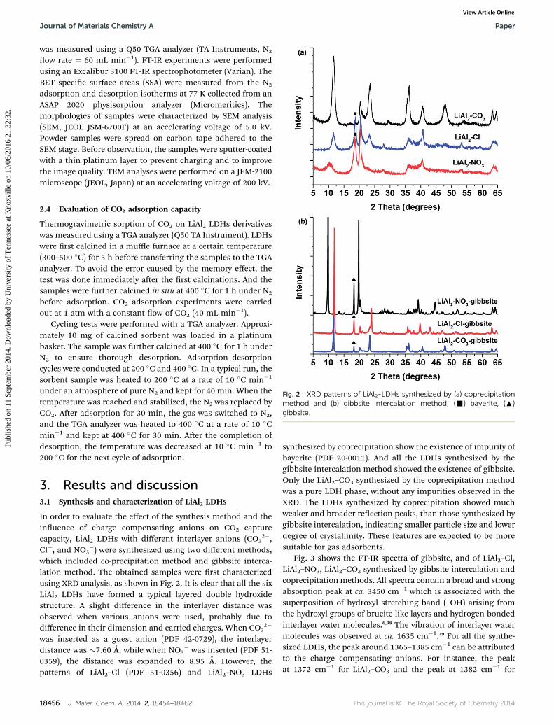
Fig. 2 XRD patterns of LiAl2-LDHs synthesized by (a) coprecipitationmethod and (b) gibbsite intercalation method; (-) bayerite, (:)gibbsite.
2.4 Evaluation of CO2 adsorption capacity
Thermogravimetric sorption of CO2 on LiAl2 LDHs derivativeswas measured using a TGA analyzer (Q50 TA Instrument). LDHswere rst calcined in a muffle furnace at a certain temperature(300–500 �C) for 5 h before transferring the samples to the TGAanalyzer. To avoid the error caused by the memory effect, thetest was done immediately aer the rst calcinations. And thesamples were further calcined in situ at 400 �C for 1 h under N2
before adsorption. CO2 adsorption experiments were carriedout at 1 atm with a constant ow of CO2 (40 mL min�1).
Cycling tests were performed with a TGA analyzer. Approxi-mately 10 mg of calcined sorbent was loaded in a platinumbasket. The sample was further calcined at 400 �C for 1 h underN2 to ensure thorough desorption. Adsorption–desorptioncycles were conducted at 200 �C and 400 �C. In a typical run, thesorbent sample was heated to 200 �C at a rate of 10 �C min�1
under an atmosphere of pure N2 and kept for 40 min. When thetemperature was reached and stabilized, the N2 was replaced byCO2. Aer adsorption for 30 min, the gas was switched to N2,and the TGA analyzer was heated to 400 �C at a rate of 10 �Cmin�1 and kept at 400 �C for 30 min. Aer the completion ofdesorption, the temperature was decreased at 10 �C min�1 to200 �C for the next cycle of adsorption.
3. Results and discussion3.1 Synthesis and characterization of LiAl2 LDHs
In order to evaluate the effect of the synthesis method and theinuence of charge compensating anions on CO2 capturecapacity, LiAl2 LDHs with different interlayer anions (CO3
2�,Cl�, and NO3
�) were synthesized using two different methods,which included co-precipitation method and gibbsite interca-lation method. The obtained samples were rst characterizedusing XRD analysis, as shown in Fig. 2. It is clear that all the sixLiAl2 LDHs have formed a typical layered double hydroxidestructure. A slight difference in the interlayer distance wasobserved when various anions were used, probably due todifference in their dimension and carried charges. When CO3
2�
was inserted as a guest anion (PDF 42-0729), the interlayerdistance was �7.60 A, while when NO3
� was inserted (PDF 51-0359), the distance was expanded to 8.95 A. However, thepatterns of LiAl2–Cl (PDF 51-0356) and LiAl2–NO3 LDHs
18456 | J. Mater. Chem. A, 2014, 2, 18454–18462
synthesized by coprecipitation show the existence of impurity ofbayerite (PDF 20-0011). And all the LDHs synthesized by thegibbsite intercalation method showed the existence of gibbsite.Only the LiAl2–CO3 synthesized by the coprecipitation methodwas a pure LDH phase, without any impurities observed in theXRD. The LDHs synthesized by coprecipitation showed muchweaker and broader reection peaks, than those synthesized bygibbsite intercalation, indicating smaller particle size and lowerdegree of crystallinity. These features are expected to be moresuitable for gas adsorbents.
Fig. 3 shows the FT-IR spectra of gibbsite, and of LiAl2–Cl,LiAl2–NO3, LiAl2–CO3 synthesized by gibbsite intercalation andcoprecipitation methods. All spectra contain a broad and strongabsorption peak at ca. 3450 cm�1 which is associated with thesuperposition of hydroxyl stretching band (–OH) arising fromthe hydroxyl groups of brucite-like layers and hydrogen-bondedinterlayer water molecules.6,38 The vibration of interlayer watermolecules was observed at ca. 1635 cm�1.39 For all the synthe-sized LDHs, the peak around 1365–1385 cm�1 can be attributedto the charge compensating anions. For instance, the peakat 1372 cm�1 for LiAl2–CO3 and the peak at 1382 cm�1 for
This journal is © The Royal Society of Chemistry 2014
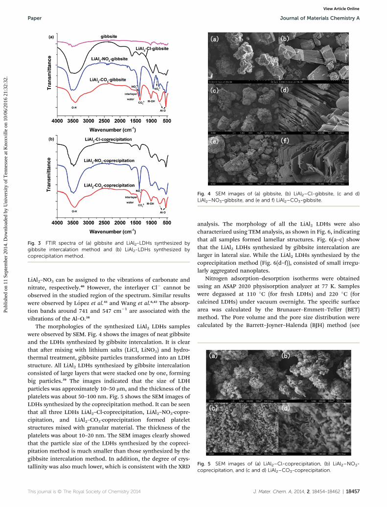
Fig. 3 FTIR spectra of (a) gibbsite and LiAl2-LDHs synthesized bygibbsite intercalation method and (b) LiAl2-LDHs synthesized bycoprecipitation method.
Fig. 4 SEM images of (a) gibbsite, (b) LiAl2–Cl-gibbsite, (c and d)LiAl2–NO3-gibbsite, and (e and f) LiAl2–CO3-gibbsite.
Fig. 5 SEM images of (a) LiAl2–Cl-coprecipitation, (b) LiAl2–NO3-
Paper Journal of Materials Chemistry A
Publ
ishe
d on
11
Sept
embe
r 20
14. D
ownl
oade
d by
Uni
vers
ity o
f T
enne
ssee
at K
noxv
ille
on 1
0/06
/201
6 21
:32:
32.
View Article Online
LiAl2–NO3 can be assigned to the vibrations of carbonate andnitrate, respectively.40 However, the interlayer Cl� cannot beobserved in the studied region of the spectrum. Similar resultswere observed by Lopez et al.41 and Wang et al.6,42 The absorp-tion bands around 741 and 547 cm�1 are associated with thevibrations of the Al–O.38
The morphologies of the synthesized LiAl2 LDHs sampleswere observed by SEM. Fig. 4 shows the images of neat gibbsiteand the LDHs synthesized by gibbsite intercalation. It is clearthat aer mixing with lithium salts (LiCl, LiNO3) and hydro-thermal treatment, gibbsite particles transformed into an LDHstructure. All LiAl2 LDHs synthesized by gibbsite intercalationconsisted of large layers that were stacked one by one, formingbig particles.39 The images indicated that the size of LDHparticles was approximately 10–50 mm, and the thickness of theplatelets was about 50–100 nm. Fig. 5 shows the SEM images ofLDHs synthesized by the coprecipitation method. It can be seenthat all three LDHs LiAl2–Cl-coprecipitation, LiAl2–NO3-copre-cipitation, and LiAl2–CO3-coprecipitation formed plateletstructures mixed with granular material. The thickness of theplatelets was about 10–20 nm. The SEM images clearly showedthat the particle size of the LDHs synthesized by the copreci-pitation method is much smaller than those synthesized by thegibbsite intercalation method. In addition, the degree of crys-tallinity was also much lower, which is consistent with the XRD
This journal is © The Royal Society of Chemistry 2014
analysis. The morphology of all the LiAl2 LDHs were alsocharacterized using TEM analysis, as shown in Fig. 6, indicatingthat all samples formed lamellar structures. Fig. 6(a–c) showthat the LiAl2 LDHs synthesized by gibbsite intercalation arelarger in lateral size. While the LiAl2 LDHs synthesized by thecoprecipitation method (Fig. 6(d–f)), consisted of small irregu-larly aggregated nanoplates.
Nitrogen adsorption–desorption isotherms were obtainedusing an ASAP 2020 physisorption analyzer at 77 K. Sampleswere degassed at 110 �C (for fresh LDHs) and 220 �C (forcalcined LDHs) under vacuum overnight. The specic surfacearea was calculated by the Brunauer–Emmett–Teller (BET)method. The Pore volume and the pore size distribution werecalculated by the Barrett–Joyner–Halenda (BJH) method (see
coprecipitation, and (c and d) LiAl2–CO3-coprecipitation.
J. Mater. Chem. A, 2014, 2, 18454–18462 | 18457

Fig. 6 TEM images of (a) LiAl2–Cl-gibbsite, (b) LiAl2–NO3-gibbsite, (c)LiAl2–CO3-gibbsite, (d) LiAl2–Cl-coprecipitation, (e) LiAl2–NO3-coprecipitation, and (f) LiAl2–CO3-coprecipitation.
Fig. 7 TGA analysis of LiAl2-LDHs with different anions synthesized by(a) coprecipitation, and (b) gibbsite interaction.
Journal of Materials Chemistry A Paper
Publ
ishe
d on
11
Sept
embe
r 20
14. D
ownl
oade
d by
Uni
vers
ity o
f T
enne
ssee
at K
noxv
ille
on 1
0/06
/201
6 21
:32:
32.
View Article Online
Table 1). It is obvious that the synthesis method greatly affectsthe SSA, pore size, and pore volume. LiAl2 LDHs synthesized bythe coprecipitation method showed a relatively high BETsurface area of 47–90 m2 g�1 and pore volume (0.3–0.6 cm3 g�1).While for the LDHs synthesized by the gibbsite intercalationmethod, the BET surface area and pore volume were very low(0.1–1.6 m2 g�1 and 0.01–0.02 cm3 g�1). The reason was becausethe LDHs synthesized by the coprecipitationmethod weremuchsmaller than the gibbsite intercalation ones, which can be seenclearly from the SEM and TEM images. Aer thermal treatment,the BET surface area of all samples was signicantly improved,with relatively smaller pore size and larger pore volume.
Table 1 Specific surface area, pore size, and pore volume of fresh and c
Samples BET SSA (m2 g�1)
LiAl2–Cl-gibbsite 1.67LiAl2–NO3-gibbsite 1.61LiAl2–CO3-gibbsite 0.09LiAl2–Cl-gibbsite-calcined 104.05LiAl2–NO3-gibbsite-calcined 58.05LiAl2–CO3-gibbsite-calcined 173.18LiAl2–Cl-coprecipitation 47.13LiAl2–NO3-coprecipitation 89.05LiAl2–CO3-coprecipitation 84.11LiAl2–Cl-coprecipitation-calcined 184.10LiAl2–NO3-coprecipitation-calcined 180.22LiAl2–CO3-coprecipitation-calciend 198.71
18458 | J. Mater. Chem. A, 2014, 2, 18454–18462
The structural evolution of the synthesized LDHs wasexamined by TGA. Fig. 7 shows the weight loss of LiAl2-copre-cipitation, gibbsite, and LiAl2-gibbsite LDHs measured byheating them to 600 �C at a rate of 10 �C min�1. The curvesfor the co-precipitation-synthesized LiAl2–Cl, LiAl2–NO3, andLiAl2–CO3 LDHs samples are all fairly similar in shape and they
alcined LiAl2 LDHs
BJH pore size (A) BJH pore volume (cm3 g�1)
442.40 0.01448.03 0.01595.36 0.0254.00 0.21
107.75 0.2135.50 0.19
108.27 0.30134.08 0.41109.23 0.57109.51 0.5998.78 0.73
149.60 0.85
This journal is © The Royal Society of Chemistry 2014
Paper Journal of Materials Chemistry A
Publ
ishe
d on
11
Sept
embe
r 20
14. D
ownl
oade
d by
Uni
vers
ity o
f T
enne
ssee
at K
noxv
ille
on 1
0/06
/201
6 21
:32:
32.
View Article Online
revealed that all LiAl2-coprecipitation LDHs were different fromthe conventional MgAl LDHs and decomposed in a single step.The dehydration, decarboxylation and dehydroxylation stepscannot be separated, similar to the result reported by Thomaset al.37 These samples exhibited very sharp decrease in mass inthe temperature range from 50 �C to 300 �C, 5% of the weightlost at ca. 120 �C accounts for the loss of intercalated water andthe surface adsorbed water. While LiAl2-gibbsite LDHs showedslightly different decomposition patterns, which had twodistinct regions of weight loss, the same as those reported byFogg et al.43 The initial weight decrease of approximately 5–12wt% was due to the loss of loosely held water in the interlayerspace. And the second weight decrease in the temperature rangeof 200–400 �C was due to dehydroxylation of the octahedrallayers as well as decomposition of the interlayer anions.Compared with LiAl2-coprecipitation LDHs, the thermalstability of LiAl2-gibbsite LDHs was higher, which may be aresult of their larger particle size and improved crystallinity.
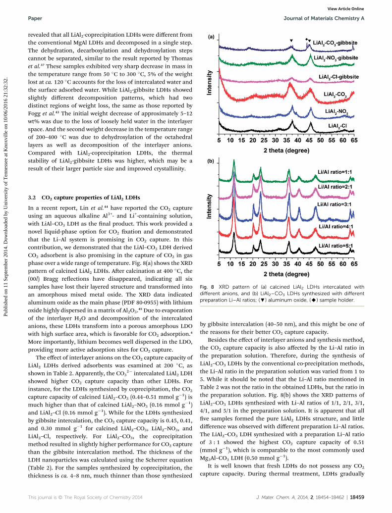
Fig. 8 XRD pattern of (a) calcined LiAl2 LDHs intercalated withdifferent anions, and (b) LiAl2–CO3 LDHs synthesized with differentpreparation Li–Al ratios; (;) aluminum oxide, (A) sample holder.
3.2 CO2 capture properties of LiAl2 LDHs
In a recent report, Lin et al.44 have reported the CO2 captureusing an aqueous alkaline Al3+- and Li+-containing solution,with LiAl–CO3 LDH as the nal product. This work provided anovel liquid-phase option for CO2 xation and demonstratedthat the Li–Al system is promising in CO2 capture. In thiscontribution, we demonstrated that the LiAl–CO3 LDH derivedCO2 adsorbent is also promising in the capture of CO2 in gasphase over a wide range of temperature. Fig. 8(a) shows the XRDpattern of calcined LiAl2 LDHs. Aer calcination at 400 �C, the(00l) Bragg reections have disappeared, indicating all sixsamples have lost their layered structure and transformed intoan amorphous mixed metal oxide. The XRD data indicatedaluminum oxide as the main phase (PDF 80-0955) with lithiumoxide highly dispersed in a matrix of Al2O3.45 Due to evaporationof the interlayer H2O and decomposition of the intercalatedanions, these LDHs transform into a porous amorphous LDOwith high surface area, which is favorable for CO2 adsorption.4
More importantly, lithium becomes well dispersed in the LDO,providing more active adsorption sites for CO2 capture.
The effect of interlayer anions on the CO2 capture capacity ofLiAl2 LDHs derived adsorbents was examined at 200 �C, asshown in Table 2. Apparently, the CO3
2� intercalated LiAl2 LDHshowed higher CO2 capture capacity than other LDHs. Forinstance, for the LDHs synthesized by coprecipitation, the CO2
capture capacity of calcined LiAl2–CO3 (0.44–0.51 mmol g�1) ismuch higher than that of calcined LiAl2–NO3 (0.16 mmol g�1)and LiAl2–Cl (0.16 mmol g�1). While for the LDHs synthesizedby gibbsite intercalation, the CO2 capture capacity is 0.45, 0.41,and 0.30 mmol g�1 for calcined LiAl2–CO3, LiAl2–NO3, andLiAl2–Cl, respectively. For LiAl2–CO3, the coprecipitationmethod resulted in slightly higher performance for CO2 capturethan the gibbsite intercalation method. The thickness of theLDH nanoparticles was calculated using the Scherrer equation(Table 2). For the samples synthesized by coprecipitation, thethickness is ca. 4–8 nm, much thinner than those synthesized
This journal is © The Royal Society of Chemistry 2014
by gibbsite intercalation (40–50 nm), and this might be one ofthe reasons for their better CO2 capture capacity.
Besides the effect of interlayer anions and synthesis method,the CO2 capture capacity is also affected by the Li–Al ratio inthe preparation solution. Therefore, during the synthesis ofLiAl2–CO3 LDHs by the conventional co-precipitation methods,the Li–Al ratio in the preparation solution was varied from 1 to5. While it should be noted that the Li–Al ratio mentioned inTable 2 was not the ratio in the obtained LDHs, but the ratio inthe preparation solution. Fig. 8(b) shows the XRD patterns ofLiAl2–CO3 LDHs synthesized with Li–Al ratios of 1/1, 2/1, 3/1,4/1, and 5/1 in the preparation solution. It is apparent that allve samples formed the pure LiAl2 LDHs structure, and littledifference was observed with different preparation Li–Al ratios.The LiAl2–CO3 LDH synthesized with a preparation Li–Al ratioof 3 : 1 showed the highest CO2 capture capacity of 0.51(mmol g�1), which is comparable to the most commonly usedMg3Al–CO3 LDH (0.50 mmol g�1).
It is well known that fresh LDHs do not possess any CO2
capture capacity. During thermal treatment, LDHs gradually
J. Mater. Chem. A, 2014, 2, 18454–18462 | 18459

Table 2 Summary of the CO2 capture capacity of synthesized LiAl2 LDHs
Samples Li–Al ratioa Thicknessb (nm) d003 (A)CO2 adsorptioncapacity (mmol g�1)
LiAl2–CO3 1 : 1 7.31 7.59 0.45LiAl2–CO3 2 : 1 8.27 7.66 0.44LiAl2–CO3 3 : 1 9.11 7.57 0.51LiAl2–CO3 4 : 1 8.68 7.51 0.49LiAl2–CO3 5 : 1 8.45 7.60 0.49LiAl2–Cl 3 : 1 7.78 7.61 0.16LiAl2–NO3 3 : 1 4.45 8.59 0.16LiAl2–Cl-gibbsite — 40.11 7.41 0.30LiAl2–NO3-gibbsite — 50.24 8.95 0.41LiAl2–CO3-gibbsite — 38.19 7.60 0.45
a The Li–Al ratio in the synthesis solution, not in the obtained samples. b Calculated using the Scherrer equation.
Journal of Materials Chemistry A Paper
Publ
ishe
d on
11
Sept
embe
r 20
14. D
ownl
oade
d by
Uni
vers
ity o
f T
enne
ssee
at K
noxv
ille
on 1
0/06
/201
6 21
:32:
32.
View Article Online
lose their interlayer water, and then get dehydroxylated anddecarbonated to a large extent, leading to the formation of amixed metal oxide.46 Fig. 9(a) shows the XRD patterns ofLiAl2–CO3-coprecipitation LDHs calcined at different tempera-tures ranging from 105–800 �C. The data revealed thatLiAl2–CO3 LDH still retained its layered double structure at150 �C. When the calcination temperature was higher than
Fig. 9 (a) XRD patterns of calcined LiAl2–CO3 LDHs at differenttemperatures, (b) the influence of calcination temperature on the CO2
capture capacity of LiAl2–CO3 LDH; (+) aluminum oxide, (-) lithiumaluminum oxide.
18460 | J. Mater. Chem. A, 2014, 2, 18454–18462
200 �C, it gradually lost its layered structure and turned intoamorphous aluminum oxide. The lithium oxide (Li2O) could notbe detected by XRD analysis, suggesting a well dispersion ofLi2O within the sample. With further increase in the calcinationtemperature to 600–800 �C, a new crystal phase of lithiumaluminum oxide (PDF 75-0905) was formed. The effect ofcalcination temperature (300–500 �C) on the CO2 capturecapacity of LiAl2–CO3 LDH was also studied, as shown inFig. 9(b). The CO2 capture capacity rst increased with theincrease in the calcination temperature up to 400 �C, and thenstarted to decrease with further increase in the calcinationtemperature from 400 to 500 �C. When the calcinationtemperature was too low (300 �C), the layered structure was notcompletely decomposed, with very weak 00l peaks still present.However, if the calcination temperature was too high, it startedto transform into other spinel oxides, which have lower surfacearea and few basicity sites for CO2 adsorption. This phenom-enon is similar to that of Mg3Al–CO3 LDHs, for which it waspreviously suggested by Wang et al.12 that the quasi-amorphousphase obtained by thermal treatment of LDHs at the lowestpossible temperature possessed the highest CO2 capturecapacity.
In order to integrate this novel CO2 adsorbent into certainprocesses, its CO2 adsorption performance at differenttemperatures is of great interest. Fig. 10(a) shows the CO2
capture capacity as a function of adsorption temperature. Theresult indicated that LiAl2–CO3 had good CO2 capture capacityover a wide temperature range. The maximum CO2 capturecapacity was reached at 60 �C (0.94 mmol g�1), and theadsorption capacity decreased with the increase in adsorptiontemperature. The adsorption capacity at 60, 100, 150, 200, 300,and 400 �C was 0.94, 0.69, 0.69, 0.51, 0.37, and 0.35 mmol g�1,respectively.
It was suggested that doping LDHs with K2CO3 enhancedthe CO2 adsorption capacity. Thus, the K2CO3 promotedLiAl2–CO3 LDH was also prepared, and the SEM images areshown in Fig. 10(b) and (c). Aer milling and calcination, themorphology of LiAl2–CO3 nanoplates changed to aggrega-tions of nanospheres. The promotion effect of K2CO3 was alsostudied with LiAl2–CO3 LDH, as shown in Fig. 9(a). Ingeneral, the CO2 adsorption capacity of K2CO3 promoted
This journal is © The Royal Society of Chemistry 2014

Fig. 10 (a) The influence of adsorption temperature on the CO2
capture capacity of LiAl2–CO3 and K2CO3 promoted LiAl2–CO3 LDHs,(b and c) SEM images of K2CO3 promoted LiAl2–CO3 LDH calcined at400 �C for 5 h in air.
Fig. 11 (a) Mass changes of LiAl2–CO3 LDH during CO2 adsorption–desorption cycles, (b) mass changes of K2CO3 promoted LiAl2–CO3
LDH during CO2 adsorption–desorption cycles, and (c) adsorptioncapacities of LiAl2–CO3 and K2CO3 promoted LiAl2–CO3 LDHs duringCO2 adsorption–desorption cycles.
Paper Journal of Materials Chemistry A
Publ
ishe
d on
11
Sept
embe
r 20
14. D
ownl
oade
d by
Uni
vers
ity o
f T
enne
ssee
at K
noxv
ille
on 1
0/06
/201
6 21
:32:
32.
View Article Online
LiAl2–CO3 also decreased with the increase of temperature.By doping the LDHs with 20 wt% K2CO3, the CO2 adsorptioncapacity was highly increased at all tested temperatures. Forinstance, the CO2 adsorption capacity at 60, 100, 150, 200,300, and 400 �C was 1.27, 0.98, 0.83, 0.83, 0.63, and 0.68mmol g�1, respectively.
For practical applications, the stability of adsorbentsduring CO2 adsorption–desorption cycles is also veryimportant. Thus, both neat LiAl2–CO3 and K2CO3 promotedLiAl2–CO3 LDHs derived adsorbents were evaluated using atypical temperature swing adsorption (TSA) process. Theadsorption was performed with pure CO2 at 200 �C for 30min, and desorption was performed with pure N2 at 400 �Cfor 30 min. Fig. 11(a) and (b) show the CO2 adsorption anddesorption performance of LiAl2–CO3 and K2CO3 promotedLiAl2–CO3 LDHs during 22 cycles. Both the results showedthat the CO2 adsorption capacity in cycle 2 was lower thanthat in cycle 1, which was due to some irreversible chemi-sorption. For neat LiAl2–CO3, the capture capacity becamestable from cycle 2, which was ca. 0.36–0.37 mmol g�1 duringthe rest 21 cycles. While for the K2CO3 promoted LiAl2–CO3
LDH, the CO2 capture capacity became stable from cycle 8,which was ca. 0.52 mmol g�1 during the rest 14 cycles.Although the CO2 capture capacity of K2CO3 promotedLiAl2–CO3 LDH dropped more than neat LiAl2–CO3 LDH, itsstable adsorption capacity was still much higher, whichprovides a better chance for applications.
This journal is © The Royal Society of Chemistry 2014
4. Conclusions
In all, we reported a novel CO2 adsorbent based on LiAl2 andpromoted LiAl2 LDHs for the rst time. By using differentsynthesis methods, a series of LiAl2 LDHs with different inter-layer anions CO3
2�, NO3�, and Cl� were synthesized and char-
acterized. The XRD analysis suggested that the pure LiAl2–CO3
LDH could be synthesized by the coprecipitation method, whileLiAl2 LDHs synthesized by the gibbsite intercalation methodhad some un-reacted gibbsite impurity. SEM and TEM imagesshowed that the LiAl2 LDHs synthesized by the coprecipitationmethod all consisted of small nanoplates aggregated togetherirregularly, and the particle size was much smaller than theones synthesized by gibbsite intercalation. Nitrogen
J. Mater. Chem. A, 2014, 2, 18454–18462 | 18461

Journal of Materials Chemistry A Paper
Publ
ishe
d on
11
Sept
embe
r 20
14. D
ownl
oade
d by
Uni
vers
ity o
f T
enne
ssee
at K
noxv
ille
on 1
0/06
/201
6 21
:32:
32.
View Article Online
adsorption–desorption analysis suggested that the LDHssynthesized by the coprecipitation method had much higherBET specic surface area than the gibbsite intercalation ones.The thermal stability of obtained LiAl2 LDHs was characterizedusing TGA analyses. Of all the samples obtained, LiAl2–CO3
showed higher CO2 capture capacity compared to LiAl2–NO3
and LiAl2–Cl. The LiAl2–CO3 LDH synthesized with a Li–Al ratioof 3 : 1 in the preparation solution had the highest CO2 capturecapacity of 0.51 (mmol g�1) at 200 �C, which is comparable tothe most commonly usedMg3Al–CO3 LDH (0.50 mmol g�1). Thebest calcination temperature for LiAl2–CO3 was 400 �C, and itshowed good CO2 capture performance over a wide temperaturerange of 60–400 �C. By doping with 20 wt% K2CO3, the CO2
adsorption capacity of LiAl2–CO3 LDH was highly increased atall temperatures. CO2 adsorption–desorption cycling testsdemonstrated that this new adsorbent had good stability aer22 cycles.
Acknowledgements
This work was supported by the Fundamental Research Fundsfor the Central Universities (TD-JC-2013-3), the Program for NewCentury Excellent Talents in University (NCET-12-0787), theBeijing Nova Program (Z131109000413013), and the NationalNatural Science Foundation of China (51308045).
Notes and references
1 S. Chu, Science, 2009, 325, 1599.2 M. Maslin, Global Warming – A Very Short Introduction,Oxford University Press, 2004.
3 Q. Wang, H. H. Tay, Z. Zhong, J. Luo and A. Borgna, EnergyEnviron. Sci., 2012, 5, 7526.
4 Q. Wang, J. Luo, Z. Zhong and A. Borgna, Energy Environ. Sci.,2011, 4, 42.
5 R. S. Haszeldine, Science, 2009, 325, 1647.6 Q. Wang, Z. Wu, H. H. Tay, L. Chen, Y. Liu, J. Chang,Z. Zhong, J. Luo and A. Borgna, Catal. Today, 2011, 164, 198.
7 Y. Gao, Z. Zhang, J. Wu, X. Yi, A. Zheng, A. Umar, D. O'Hareand Q. Wang, J. Mater. Chem. A, 2013, 1, 12782.
8 P. D. Cobden, P. van Beurden, H. T. J. Reijers, G. D. Elzinga,S. C. A. Kluiters, J. W. Dijkstra, D. Jansen and R. W. van denBrink, Int. J. Greenhouse Gas Control, 2007, 1, 170.
9 M. G. Plaza, C. Pevida, B. Arias, M. D. Casal, C. F. Martın,J. Fermoso, F. Rubiera and J. J. Pis, J. Environ. Eng., 2009,135, 426.
10 H. K. Rusten, E. Ochoa-Fernandez, H. Lindborg, D. Chenand H. A. Jakobsen, Ind. Eng. Chem. Res., 2007, 46, 8729.
11 X. Wang, J. Yu, J. Cheng, Z. Hao and Z. Xu, Environ. Sci.Technol., 2008, 42, 614.
12 Q. Wang, H. H. Tay, D. J. Ng, L. Chen, Y. Liu, J. Chang,Z. Zhong, J. Luo and A. Borgna, ChemSusChem, 2010, 3, 965.
13 D. P. Harrison, Ind. Eng. Chem. Res., 2008, 47, 6486.14 A. V. Besserguenev, A. M. Fogg, S. J. P. R. J. Francis and
D. O'Hare, Chem. Mater., 1997, 9, 241.15 A. M. Fogg, G. R. Williams, R. Chester and D. O'Hare, J.
Mater. Chem., 2004, 14, 2369.
18462 | J. Mater. Chem. A, 2014, 2, 18454–18462
16 S. Britto, G. S. Thomas, P. Vishnu Kamath and S. Kannan, J.Phys. Chem. C, 2008, 112, 9510.
17 J. P. Thiel, C. K. Chiang and K. R. Poeppelmeier, Chem.Mater., 1993, 5, 297.
18 G. S. Thomas, P. Vishnu Kamath and S. Kannan, J. Phys.Chem. C, 2007, 111, 18980.
19 A. Ragavan, G. R. Williams and D. O'Hare, J. Mater. Chem.,2009, 19, 4211.
20 N. D. Hutson, Chem. Mater., 2004, 16, 4135.21 G. R. Williams, T. G. Dunbar, A. J. Beer, A. M. Fogg and
D. O'Hare, J. Mater. Chem., 2006, 16, 1231.22 G. R. Williams and D. O'Hare, Chem. Mater., 2005, 17, 2632.23 G. R. Williams, N. H. Rees and D. O'Hare, Solid State Sci.,
2009, 11, 1229.24 L. Lei, R. P. Vijayan and D. O'Hare, J. Mater. Chem., 2001, 11,
3276.25 Q. Wang, J. P. Undrell, Y. Gao, G. Cai, J.-C. Buffet,
C. A. Wilkie and D. O'Hare, Macromolecules, 2013, 46, 6145.26 L. He, Y. Huang, A. Wang, X. Wang, X. Chen, J. J. Delgado
and T. Zhang, Angew. Chem., Int. Ed., 2012, 51, 6191.27 Y. Zhao, S. He, M. Wei, D. G. Evans and X. Duan, Chem.
Commun., 2010, 46, 3031.28 Q. Wang, Y. Gao, J. Luo, Z. Zhong, A. Borgna, Z. Guo and
D. O'Hare, RSC Adv., 2013, 3, 3414.29 S. Li, Y. Shi, Y. Yang, Y. Zheng and N. Cai, Energy Fuels, 2013,
27, 5352.30 P. H. Chang, T. J. Lee, Y. P. Chang and S. Y. Chen,
ChemSusChem, 2013, 6, 1076.31 Y. Lwin and F. Abdullah, J. Therm. Anal. Calorim., 2009, 97,
885.32 N. D. Hutson and B. C. Attwood, Adsorption, 2008, 14, 781.33 U. Sharma, B. Tyagi and R. V. Jasra, Ind. Eng. Chem. Res.,
2008, 47, 9588.34 M. K. R. Reddy, Z. P. Xu, G. Q. M. Lu and J. C. D. d. Costa, Ind.
Eng. Chem. Res., 2006, 45, 7504.35 Q. Wang, H. H. Tay, L. Chen, Y. Liu, J. Chang, Z. Zhong,
J. Luo and A. Borgna, J. Nanoeng. Nanomanuf., 2011, 1, 298.36 M. Kato and K. Nakagawa, J. Ceram. Soc. Jpn., 2001, 109, 911.37 G. S. Thomas and P. V. Kamath, Mater. Res. Bull., 2002, 37,
705.38 J. Wang, Z. Lei, H. Qin, L. Zhang and F. Li, Ind. Eng. Chem.
Res., 2011, 50, 7120.39 C. J. Wang and D. O'Hare, J. Mater. Chem., 2012, 22, 23064.40 Z.-L. Hsieh, M.-C. Lin and J.-Y. Uan, J. Mater. Chem., 2011, 21,
1880.41 T. Lopez, P. Bosch, M. Asomoza, R. Gomez and E. Ramos,
Mater. Lett., 1997, 31, 311.42 H. Zeng, Z. Feng, X. Deng and Y. Li, Fuel, 2008, 87, 3071.43 A. M. Fogg, A. J. Freij and G. M. Parkinson, Chem. Mater.,
2002, 14, 232.44 M.-C. Lin, F.-T. Chang and J.-Y. Uan, J. Mater. Chem. A, 2013,
1, 14773.45 J. L. Shumaker, C. Crofcheck, S. A. Tackett, E. Santillan-
Jimenez and M. Crocker, Catal. Lett., 2007, 115, 56.46 W. Yang, Y. Kima, P. K. T. Liu, M. Sahimi and T. T. Tsotsis,
Chem. Eng. J., 2002, 57, 2945.
This journal is © The Royal Society of Chemistry 2014