Embed Size (px)
Citation preview
Journal of Machine Engineering, 2018, Vol. 18, No. 4, 5–24
ISSN 1895-7595 (Print) ISSN 2391-8071 (Online)
Received: 06 February 2018 / Accepted: 16 November 2018 / Published online: 20 December 2018
hybrid manufacturing, CNC machining,
additive machining, laser cladding,
repair technology
Wit GRZESIK1*
HYBRID ADDITIVE AND SUBTRACTIVE MANUFACTURING PROCESSES
AND SYSTEMS: A REVIEW
This review paper highlights the hybrid manufacturing processes which integrate the additive and subtractive
processes performing on one hybrid platform consisting of the LMD (laser metal deposition) unit and CNC
machine tools. In particular, some important rules and advantages as well as technological potentials
of the integration of different AM technique and finishing CNC machining operations are discussed and
overviewed. Some representative examples such as formation of difficult features around the part periphery,
deposition of functional layers and coatings and repair of high-value parts in aerospace industry are provided.
Some conclusions and future trends in the implementation of hybrid processes are outlined.
1. INTRODUCTION
Hybridization of is one of the leading strategies in developing more flexible and
efficient manufacturing processes and implementing them into Production/Manufacturing
4.0 environment. In general, hybridization includes conventional and unconventional
manufacturing/ machining processes using two rules, i.e. combination of different energy
sources/tools or controlled applications of process mechanisms [1]. On the other hand,
the concept of hybrid machining/manufacturing systems in which two or more individual
machining/manufacturing processes are combined into one system is developed.
In particular, hybrid machine tools (e.g. mill-turn centers) integrate different machining
operations within one machining platform. Accordingly, the multi-tasking or complete
machining is also defined [2]. Recently, a new trend in developing hybrid manufacturing
processes combining additive (AM) and subtractive (SM) processes, which are performed
on one hybrid manufacturing platform consisting of a multi-functional (multi-tasking) CNC
machine tool and AM module along with automatic 3D scanning and dimensional control
abilities, is observed [2, 3]. It should be noticed that additive manufacturing is commonly
_____________ 1 Faculty of Mechanical Engineering, Opole University of Technology, Opole, Poland
* E-mail: [email protected]
https://doi.org/10.5604/01.3001.0012.7629
6 W. Grzesik/Journal of Machine Engineering, 2018, Vol. 18, No. 4, 5–24
termed 3D printing. As a result, additive fabrication and finish machining of a part is carried
out on one machine without any additional fixing and transportation.
The main reasons for the use of hybrid additive systems in low volume production,
high construction variability of parts include [4–6]:
1. Repair – Hybrid machines allow to use either additive or subtractive process and
the main application for hybrid systems is repair of currently existing components
2. Surface finish–By coupling the additive technique seamlessly with CNC milling, all
internal and external surfaces can be milled to traditional CNC surface finish.
3. Precision – Hybrid additive manufacturing allows every surface to be printed and
milled in the same reference coordinate system, allowing tighter tolerances.
4. Adding difficult features– In traditional manufacturing, multiple parts are bolted,
welded, and brazed into a final product. On the other hand, hybrid additive
manufacturing design reduces complicated, multiple-part into one single part and
difficult features are added around the periphery. A single part building reduces time,
labour and cost to one part.
5. Multi-metal 3D printing – Parts consisting of multiple metals are difficult to produce
even with additive manufacturing. A hybrid system architecture allows for a part to
start with a preform of material A, add material B using additive manufacturing, and
then switch to material C for further additive manufacturing.
In general, additive manufacturing uses the powder and wire technology [7] and two
deposition methods are mainly utilize, i.e. laser cladding and arc welding in order to
fabricate the near-net shaped parts directly from CAD models. Usually, the powder
technology is adapted for fine components and small parts, whereas wire technology is
recommended for large structural components. However, a CNC finish machining is
implemented to ensure desired accuracy by eliminating the stars effects resulting from
deposition of certain layers (Fig. 1b).
The spectrum of possible solutions is very broad including the fabrication of additional
complex features using 3D printing and blown-powder melting (LMD-laser metal
deposition), deposition of additional elements made of materials different than the base
(substrate) material, as well as remanufacturing/regeneration of damaged/worn high-value
parts. In production practice, several equivalent names for directed energy deposition by
laser or electron beam are used including:
• Laser powder fusion welding,
• Directed metal deposition,
• Reverse machining laser cast,
• Laser cladding.
It is well known that laser-sintered additive manufacturing is at least one order
of magnitude slower than traditional CNC metal removal (subtractive) process.
The technological dilemma is to select higher productivity and thicker deposition layer (but
lower surface finish due to the “stairs effect” shown in Fig. 1a) or improve surface finish by
performing a slower deposition of thinner layers. In other words, the productivity of an AM
process can be increased with much higher energy input, yielding thicker layers of powder
and much faster builds, but the surface finish deteriorates (see Fig. 1b).

W. Grzesik/Journal of Machine Engineering, 2018, Vol. 18, No. 4, 5–24 7
In contrast, the slow process, producing smaller layers, creating a better surface finish
can be accepted. Even with the slower process – producing thinner layers for better surface
finish – further post-deposition processing on some type of CNC machine platform is
needed. This is where the struggle has always been between additive and subtractive
manufacturing. This is an argument that these processes have been seen as competing
technologies instead of being complementary to one another (Fig. 1a). On the other hand,
hybrid process is the bridge allowing to print material, add metal to existing components,
grow parts from zero volume, and then to machine them in that same envelope (see Fig. 1b).
As a result, hybrid machining process integrating the AM and SM CNC operations becomes
a profitable process for small and medium batches due to the fact that the productivity and
surface finish can be controlled independently [3].
a)
b)
Fig. 1. Comparison of pure additive and subtractive processes and hybrid process (a), effects of integration of AM
and SM CNC processes [8]
Hybridizing between additive and subtractive processes is currently almost standard
practice for the vast majority of metallic parts produced by AM which additionally require
machining in order to obtain a suitable surface finish (see Fig. 1b), narrower dimensional
tolerances and functional properties, and avoid excessive residual stresses or even improve
cosmetics, etc. It also results in substantial reducing scraps due to the fact that powder or foil
are used instead solid blanks made of aluminium or titanium for which in aerospace industry
80÷90% material volume is removed when machining complex monolithic parts [2].
As mentioned above the need for integrating additive and subtractive processes is to
produce complex part geometries directly from a CAD model (Fig. 3) with minimal
machining to achieve precision part-feature accuracy and fine surface finish. A unique
integration between direct metal deposition (DMD) which is used for additive
manufacturing and subtractive machining in CNC-RP is shown in Fig. 2.
This system termed AIMS (Additive system Integrated with subtractive MethodS)
integrates process capabilities of two different manufacturing approaches, i.e. EBM
(electron beam melting) or DMLS (direct metal laser sintering) and rapid CNC (CNC-RP)
machining to create near-net shaped complex parts. Fig. 2 illustrates the basic concept
of the AIMS system which creates a metal linkage via AM (EBM) and SM (CNC-RP)

8 W. Grzesik/Journal of Machine Engineering, 2018, Vol. 18, No. 4, 5–24
processes. In particular, a direct metal process creates not only a near-net shape of the
desired part but also fixture elements are attached for a subsequent rapid machining process.
The AIMS process utilizes two kinds of sacrificial supports, first to support overhangs
in AM process and second to support the part in a CNC machine fixture. Figs. 3a and 3b
show two parts, a hinge component from an airframe (a) and a suspension part from
a bicycle (b), with sacrificial fixtures (prior to removing them after machining). Fig. 3c
presents the machining time and number of tools used for different materials including Al
6061 aluminium alloy, SS 316L stainless steel and Ti6-4 titanium alloy. In this analysis
the cutting tool change time was not considered in the total machining time. It can be
reasoned that machining duration of CNC-RP production is significantly longer that AIMS
because only the finishing stage of CNC-RP is taken into account in the hybrid process
(1590 min and 3432 min for a suspension part and the airframe hinge made of Ti6-4
alloy respectively).
Fig. 2. Flow of the AIMS process including AM (EBM- electron beam melting or DMLS- direct metal laser sintering)
and SM (CNC-RP) [9]
a) Suspender part
c) total machining time
b) Hinge part
Fig. 3. Examples of machined parts: hinge (a) and suspension (b) parts after machining and prior to removing sacrificial
fixtures, (c) influence of material selection on total machining time for RP using CNC machine tool [9]
W. Grzesik/Journal of Machine Engineering, 2018, Vol. 18, No. 4, 5–24 9
2. FUNDAMENTALS OF HYBRID ADDITIVE-SUBTRACTIVE MANUFACTURING
2.1. INTEGRATION RULES OF ADDITIVE AND SUBTRACTIVE PROCESSES
As reported in many literature and industrial sources, as for instance [8–11]
appropriate research efforts are focused on the design of a modular hybrid manufacturing
platform which integrates various additive techniques (AM) with finish machining
(subtractive processes (SM CNC), including:
– FDM/extruding on different types of CNC machine tools,
– SLM on the vertical machining center (VMC), for example Lumex Advance-25,
Matsuura, Japan.
– Direct metal deposition (DMD), as for instance laser cladding on the multi-
functional/multi-axis machining centers, for example Hamuel HSTM 1000 (5-axis
turning –milling center), GF HPM 450U (5-axis milling center equipped with
a rotating-tilting table), DMG Mori Lasertec 65 3D (5-axis milling center), Mazak
VC-500 AM (5-axis vertical milling center).
As can be noted multi-axis milling centers are the basic machine tools utilized for
the platform for installation of an AM module. The second variant, more rarely used, is
based on a turning-milling center which allows performing both turning and milling
operations using the same workpiece alignment.
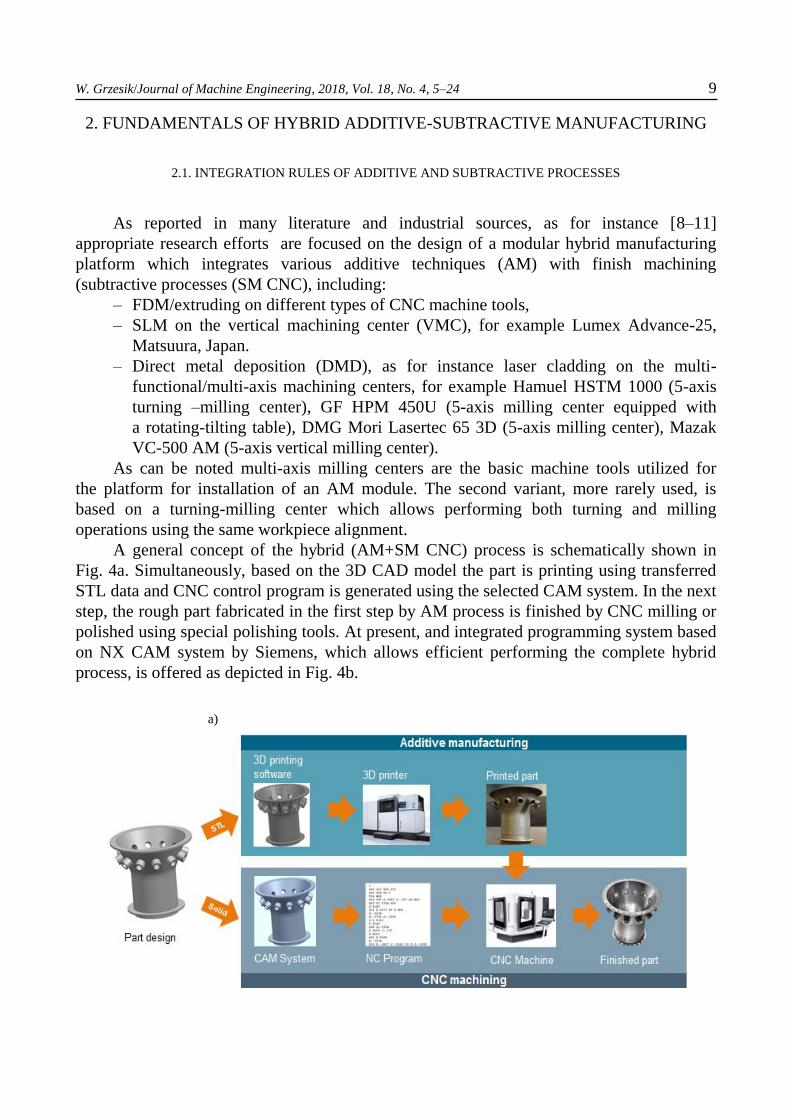
A general concept of the hybrid (AM+SM CNC) process is schematically shown in
Fig. 4a. Simultaneously, based on the 3D CAD model the part is printing using transferred
STL data and CNC control program is generated using the selected CAM system. In the next
step, the rough part fabricated in the first step by AM process is finished by CNC milling or
polished using special polishing tools. At present, and integrated programming system based
on NX CAM system by Siemens, which allows efficient performing the complete hybrid
process, is offered as depicted in Fig. 4b.
a)

10 W. Grzesik/Journal of Machine Engineering, 2018, Vol. 18, No. 4, 5–24
b)
Fig. 4. General concept of technological (a) and programming integration (b) of additive and subtractive processes
(AM+SM CNC) according to Siemens [8]
The basic design problem which appears in the synergetic integration AM and SM
techniques is the installation of an AM module on a new or partly exploited CNC machine
tool without its fundamental modifying or after retrofitting. The first concept was proposed
within the pioneered research project RECLAIM (REmanufacture of high value products
using a Combined LAser cladding, Inspection and Machining system) which was finished in
2009 [8, 12]. It was recommended there a profitable retrofitting of new CNC machine tools
by adding a laser cladding module as shown in Fig. 7. It should be noted that one of the first
hybrid machine tools manufactured by AeroMet Corp., which integrated laser cladding/laser
deposition on a CNC milling machine was applied in 2004 for production
of materials/products in the aerospace industry for a F-15 fighter. This system was not so
efficient as demanded due to technical problems with the CO2 laser and powder supplying
(additionally the manifold is attached to the laser head in order to dock the powder during
deposition phase).
a)
b)
Fig. 5. Storage of cladding head (3), ball end-mill cutter (1) and touch probe (2) in the automated tool changer (below
typical changeable laser cladding head- versions A and B in Fig. 6) (a), tool magazine in hybrid vertical manufacturing
platform equipped with several milling cutters and laser cladding head (b) [8, 13]
W. Grzesik/Journal of Machine Engineering, 2018, Vol. 18, No. 4, 5–24 11
2.2. DESIGN OF HYBRID MACHINES AND TOOLING
Next important innovative design problem for the machine tool builder, which
naturally follows the adding of a AM module (DED – directed metal deposition module) to
the basic machine structure, is to use the standard tool holders, as for instance HSK 63 taper,
for mounting the head into the spindle (see Fig. 5b). Moreover, the laser head should be
stored out of the working area of the CNC machine and the manifold undocked after
deposition operations (i.e. when the LMD head is replaced by the milling cutter). Of course,
the workpiece should be electrically grounded when arc-based welding approach is
alternatively used in order to avoid the catastrophic consequences of the high arc voltage
through the CNC machine itself.
Hybrid Manufacturing’s Ambit system (Fig. 5) offers seven different laser deposition
heads, each of which is fully compatible with a standard tool changer and any standard
machine spindle (CAT 40, HSK63, etc). The heads automatically link up with a supply unit
to deliver the laser energy, shield gas, and powder supply. The use of a standard tool
changer allows the expanded capability of the laser-based hybrid system by application
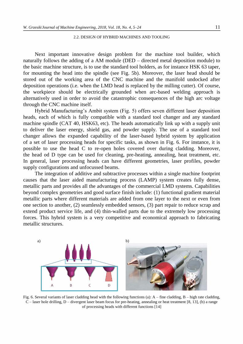
of a set of laser processing heads for specific tasks, as shown in Fig. 6. For instance, it is
possible to use the head C to re-open holes covered over during cladding. Moreover,
the head od D type can be used for cleaning, pre-heating, annealing, heat treatment, etc.
In general, laser processing heads can have different geometries, laser profiles, powder
supply configurations and unfocussed beams.
The integration of additive and subtractive processes within a single machine footprint
causes that the laser aided manufacturing process (LAMP) system creates fully dense,
metallic parts and provides all the advantages of the commercial LMD systems. Capabilities
beyond complex geometries and good surface finish include: (1) functional gradient material
metallic parts where different materials are added from one layer to the next or even from
one section to another, (2) seamlessly embedded sensors, (3) part repair to reduce scrap and
extend product service life, and (4) thin-walled parts due to the extremely low processing
forces. This hybrid system is a very competitive and economical approach to fabricating
metallic structures.
a)
b)
Fig. 6. Several variants of laser cladding head with the following functions (a): A – fine cladding, B – high rate cladding,
C – laser hole drilling, D – divergent laser beam focus for pre-heating, annealing or heat treatment [8, 13], (b) a range
of processing heads with different functions [14]
12 W. Grzesik/Journal of Machine Engineering, 2018, Vol. 18, No. 4, 5–24
Beam-directed technologies, such as laser cladding, are very easy to integrate with
other processes and computer numerically controlled (CNC) milling machines by simply
mounting the cladding head to the z-axis of the milling machine. For instance, retrofitted
5-axis milling machine with a Nd:YAG laser cladding head and powder feeding unit are all
controlled by extended CNC-control. Similarly, a Direct Laser Deposition (DLD) process
utilizing an Nd:YAG laser, coaxial powder nozzle and digitizing system was integrated into
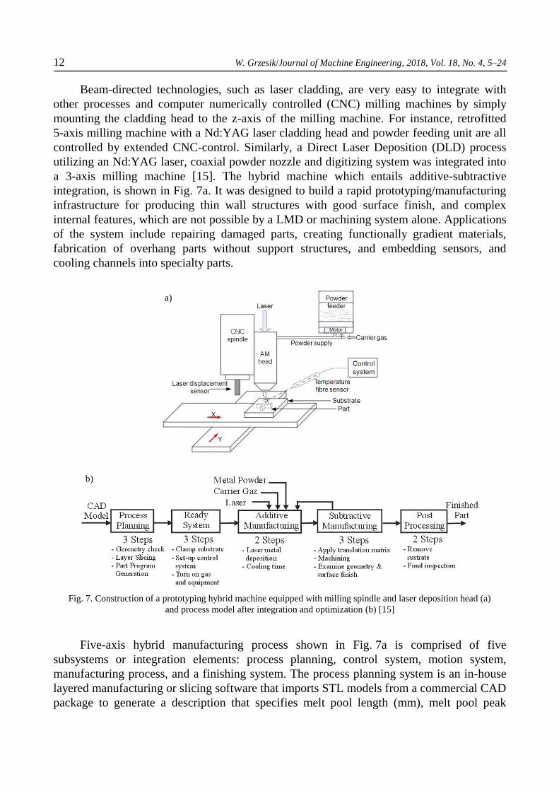
a 3-axis milling machine [15]. The hybrid machine which entails additive-subtractive
integration, is shown in Fig. 7a. It was designed to build a rapid prototyping/manufacturing
infrastructure for producing thin wall structures with good surface finish, and complex
internal features, which are not possible by a LMD or machining system alone. Applications
of the system include repairing damaged parts, creating functionally gradient materials,
fabrication of overhang parts without support structures, and embedding sensors, and
cooling channels into specialty parts.
Fig. 7. Construction of a prototyping hybrid machine equipped with milling spindle and laser deposition head (a)
and process model after integration and optimization (b) [15]
Five-axis hybrid manufacturing process shown in Fig. 7a is comprised of five
subsystems or integration elements: process planning, control system, motion system,
manufacturing process, and a finishing system. The process planning system is an in-house
layered manufacturing or slicing software that imports STL models from a commercial CAD
package to generate a description that specifies melt pool length (mm), melt pool peak
a)
b)
W. Grzesik/Journal of Machine Engineering, 2018, Vol. 18, No. 4, 5–24 13
temperature, clad height (mm) and sequences of operations. The objective of the process
planning software is to integrate the five-axis motion and deposition-machining hybrid
processes (Fig. 7b). Control of the hybrid manufacturing subsystems require a versatile
industrial controller (the National Instruments Real Time Control System (NI RT System)
and a range of sensors to acquire feedback. System feedback is acquired through
temperature and laser displacement sensors (Fig. 7a). An Omron Z4M-W100 laser
displacement sensor is used to digitally determine the cladding head height above
the substrate. There are danger zones and safe zones that the nozzle can be with respect to
the substrate. Output of the displacement sensor is converted into a minimum and maximum
distance value, respectively. The temperature sensor is a non- contact, fiber-optic, infrared
temperature sensor. It was installed onto the Z-axis of the VMC. There is also a machine
vision system, an image sensor, to watch the melt pool in real-time.
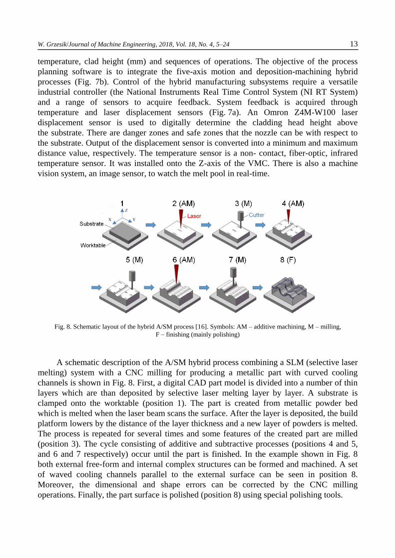
Fig. 8. Schematic layout of the hybrid A/SM process [16]. Symbols: AM – additive machining, M – milling,
F – finishing (mainly polishing)
A schematic description of the A/SM hybrid process combining a SLM (selective laser
melting) system with a CNC milling for producing a metallic part with curved cooling
channels is shown in Fig. 8. First, a digital CAD part model is divided into a number of thin
layers which are than deposited by selective laser melting layer by layer. A substrate is
clamped onto the worktable (position 1). The part is created from metallic powder bed
which is melted when the laser beam scans the surface. After the layer is deposited, the build
platform lowers by the distance of the layer thickness and a new layer of powders is melted.
The process is repeated for several times and some features of the created part are milled
(position 3). The cycle consisting of additive and subtractive processes (positions 4 and 5,
and 6 and 7 respectively) occur until the part is finished. In the example shown in Fig. 8
both external free-form and internal complex structures can be formed and machined. A set
of waved cooling channels parallel to the external surface can be seen in position 8.
Moreover, the dimensional and shape errors can be corrected by the CNC milling
operations. Finally, the part surface is polished (position 8) using special polishing tools.

14 W. Grzesik/Journal of Machine Engineering, 2018, Vol. 18, No. 4, 5–24
2.3. PRACTICAL EXAMPLES OF APPLICATIONS OF HYBRID (A/SM) PROCESSES
A novel additive/subtractive hybrid manufacturing (A/SM) method is rapidly
developed in last years for many applications such as [4, 8, 17–19]: producing complex parts
with high accuracy and good surface finish, producing parts with overhang elements, flanges
and fins (Figs. 9c and 11a), repairs of worn elements in one clamping and producing multi-
material parts using 3D printing (e.g. local deposition of Inconel 718 on the hollow shaft in
Fig. 9c). This method is particularly suited to small-lot production of difficult-to-machine
materials, such as aerospace alloys, high-hardness materials used in the energy, die and
mould, tooling and medical device sectors.
Injection mold presented in Fig. 9a was made of the 18Ni (C300) maraging steel
powders of the 35 µm particle size using the additive SLM and high speed milling
processes. A stainless steel plate was used as a substrate and the deposited layer thickness
was equal to 40 µm. A special laser scanning strategy was applied in order to avoid
excessive residual stresses and, as a result, to minimize distortions and cracks [8]. The laser
beam was travelled at the speed of 1400 mm/s with a 0.2 m spot diameter. The workpiece
temperature during high speed milling operations was relatively high because the molten
pool in the previous AM process. In general, the part is heat treated after the A/SM hybrid
process.
a)
CAD model
b)
c)
Fig.9. Injection mold with internal cooling channels produced by hybrid A/SM (Additive/Subtractive Manufacturing)
process (a), injection mold for the head of electric driver produced by hybrid process including SLM and CNC milling
(b) and cylinder shaft for oil industry with locally deposited layers of Inconel 718 alloy (c) [5–6, 8, 16–18]. Symbols:
AM/T – additive process plus turning (1), AM/M – additive process plus milling (2, 3, 4), LM – laser marking (5)
The mold made of a maraging steel shown in Fig. 9b was produced on a hybrid
Matsuura Lumex Avance-25 machine using a special AM process, which combines powder
bed fusion with selective laser melting (3D-SLS), and high speed milling [20]. The process
begins when the laser melts a specified thickness of powder. This layer thickness can vary
based on the material that is being sintered. The machine is equipped with a two-blade
W. Grzesik/Journal of Machine Engineering, 2018, Vol. 18, No. 4, 5–24 15
squeezing system which works in such a way that the leading blade clears the path for
the new powder layer, and the trailing blade smooths and compacts the new powder layer.
A machining pass typically follows after every 10 sintering passes, but this is a variable that
can be set by the user. The hybrid process reduces substantially costs and practically
eliminates EDM from the die and mould making technology.
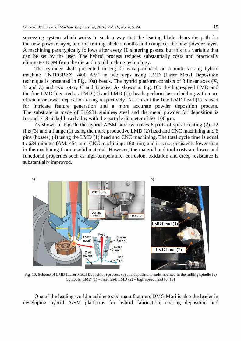
The cylinder shaft presented in Fig. 9c was produced on a multi-tasking hybrid
machine “INTEGREX i-400 AM” in two steps using LMD (Laser Metal Deposition
technique is presented in Fig. 10a) heads. The hybrid platform consists of 3 linear axes (X,
Y and Z) and two rotary C and B axes. As shown in Fig. 10b the high-speed LMD and
the fine LMD (denoted as LMD (2) and LMD (1)) heads perform laser cladding with more
efficient or lower deposition rating respectively. As a result the fine LMD head (1) is used
for intricate feature generation and a more accurate powder deposition process.
The substrate is made of 316S31 stainless steel and the metal powder for deposition is
Inconel 718 nickel-based alloy with the particle diameter of 50–100 µm.
As shown in Fig. 9c the hybrid A/SM process makes 6 parts of spiral coating (2), 12
fins (3) and a flange (1) using the more productive LMD (2) head and CNC machining and 6
pins (bosses) (4) using the LMD (1) head and CNC machining. The total cycle time is equal
to 634 minutes (AM: 454 min, CNC machining: 180 min) and it is not decisively lower than
in the machining from a solid material. However, the material and tool costs are lower and
functional properties such as high-temperature, corrosion, oxidation and creep resistance is
substantially improved.
a)
b)
Fig. 10. Scheme of LMD (Laser Metal Deposition) process (a) and deposition heads mounted in the milling spindle (b)
Symbols: LMD (1) – fine head, LMD (2) – high speed head [6, 19]
One of the leading world machine tools’ manufacturers DMG Mori is also the leader in
developing hybrid A/SM platforms for hybrid fabrication, coating deposition and
16 W. Grzesik/Journal of Machine Engineering, 2018, Vol. 18, No. 4, 5–24
remanufacturing/repair [11]. Standard universal hybrid machine is a machining center
Lasertec 65 3D (see Fig. 18a) which uses the blown-powder deposition welding process
(the metallic powder stream is sprayed to the melt pool (Fig. 11c1) and fused to
the substrate). This AM technique is more efficient than laser sintering (STL) and for
instance the part of 3.5 kg mass is build 20 times faster, and due to the high accuracy high
speed milling operations can be employed wherever fine precision is needed or some critical
features should be machined. A hybrid machine tool combining laser metal deposition for
additive manufacturing with five-axis CNC simultaneous machining is equipped with
the 2 kW diode laser head located in the machine’s spindle with an HSK interface. For
the shift to machining mode, this head swivels to a protected parking area. By using laser
deposition to build up the part, while employing milling throughout the process to machine
critical features as the part is taking shape, the machine can produce a component through
additive manufacturing while also producing it to its completed tolerances within
the same cycle.
a) AM+M/T CNC
1
2
b) AM+T CNC
b1)
c) DMD/repair
c1)
c2)
3
4
5
7
b2)
6
8
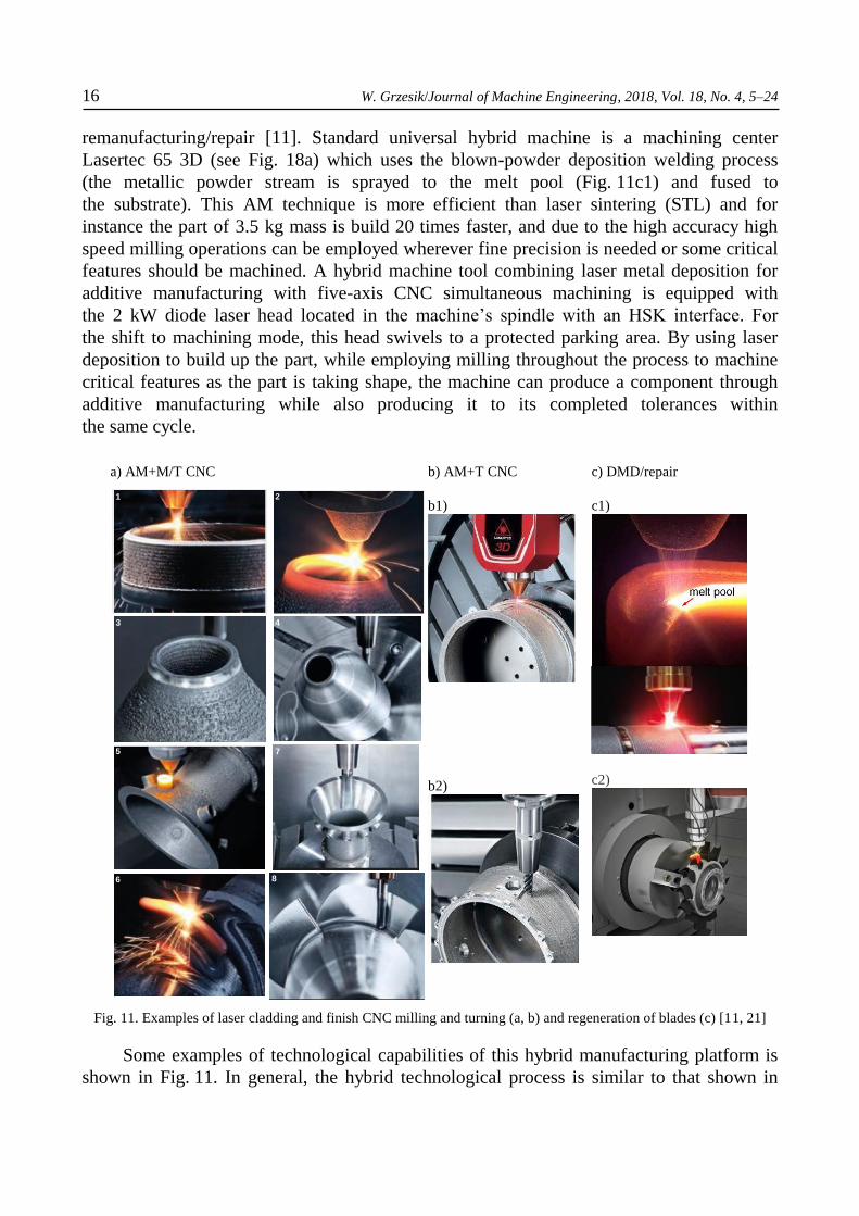
Fig. 11. Examples of laser cladding and finish CNC milling and turning (a, b) and regeneration of blades (c) [11, 21]
Some examples of technological capabilities of this hybrid manufacturing platform is
shown in Fig. 11. In general, the hybrid technological process is similar to that shown in
W. Grzesik/Journal of Machine Engineering, 2018, Vol. 18, No. 4, 5–24 17
Fig. 8. After deposition of the cylindrical (1) and conical (2) elements the part is milled (3)
and finished (4). Another construction variant of the part include additional deposition
of a number of bosses (5) or helical flanges (6) and finish milling (7, 8) of the blank.
Recently, the second hybrid machine which adds the possibility of turning operations (b1) to
laser deposition welding and 5-axis CNC milling (b2). As a result, rotational-symmetric
components can be produced with the hybrid A/SM process, as shown in Fig. 11b.
The machine is equipped with a mirrored C axis and workpieces can be machined on
the rear side with the counter-spindle enabling six-sided machining of the finished part.
Moreover, the rotational table is employed in the laser cladding for deposition or repair
of blades of rotors as shown in Fig. 11c.
In ref. [7] a multi-AM process platform including Wire Arc Additive Manufacturing
(WAAM), High Speed Machining (HSM) and Laser Metal Deposition (LMD) is used in
the laboratory scale to manufacture complex large parts made of aluminium alloys.
In general, five axis toolpaths are recommended to obtain an acceptable accuracy.
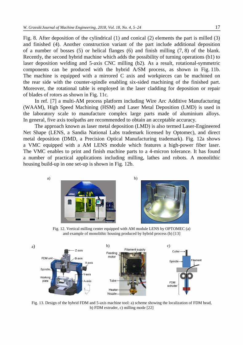
The approach known as laser metal deposition (LMD) is also termed Laser-Engineered
Net Shape (LENS, a Sandia National Labs trademark licensed by Optomec), and direct
metal deposition (DMD, a Precision Optical Manufacturing trademark). Fig. 12a shows
a VMC equipped with a AM LENS module which features a high-power fiber laser.
The VMC enables to print and finish machine parts to a 4-micron tolerance. It has found
a number of practical applications including milling, lathes and robots. A monolithic
housing build-up in one set-up is shown in Fig. 12b.
a)
b)
Fig. 12. Vertical milling center equipped with AM module LENS by OPTOMEC (a)
and example of monolithic housing produced by hybrid process (b) [13]
a)
b)
c)
Fig. 13. Design of the hybrid FDM and 5-axis machine tool: a) scheme showing the localization of FDM head,
b) FDM extruder, c) milling mode [22]
18 W. Grzesik/Journal of Machine Engineering, 2018, Vol. 18, No. 4, 5–24
A relatively new idea is to integrate the FDM (fused deposition modelling) rapid
prototyping technique with CNC milling, as illustrated in Fig. 13a. It is the case
of mechanical design where the FDM extruder (Fig. 13b) and the cutting spindle are
integrated and controlled in the frame of 5-axis machine tool. Its main application area
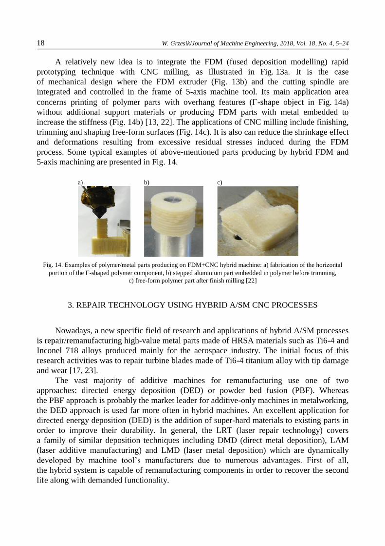
concerns printing of polymer parts with overhang features (-shape object in Fig. 14a)
without additional support materials or producing FDM parts with metal embedded to
increase the stiffness (Fig. 14b) [13, 22]. The applications of CNC milling include finishing,
trimming and shaping free-form surfaces (Fig. 14c). It is also can reduce the shrinkage effect
and deformations resulting from excessive residual stresses induced during the FDM
process. Some typical examples of above-mentioned parts producing by hybrid FDM and
5-axis machining are presented in Fig. 14.
a)
b)
c)
Fig. 14. Examples of polymer/metal parts producing on FDM+CNC hybrid machine: a) fabrication of the horizontal
portion of the -shaped polymer component, b) stepped aluminium part embedded in polymer before trimming,
c) free-form polymer part after finish milling [22]
3. REPAIR TECHNOLOGY USING HYBRID A/SM CNC PROCESSES
Nowadays, a new specific field of research and applications of hybrid A/SM processes
is repair/remanufacturing high-value metal parts made of HRSA materials such as Ti6-4 and
Inconel 718 alloys produced mainly for the aerospace industry. The initial focus of this
research activities was to repair turbine blades made of Ti6-4 titanium alloy with tip damage
and wear [17, 23].
The vast majority of additive machines for remanufacturing use one of two
approaches: directed energy deposition (DED) or powder bed fusion (PBF). Whereas
the PBF approach is probably the market leader for additive-only machines in metalworking,
the DED approach is used far more often in hybrid machines. An excellent application for
directed energy deposition (DED) is the addition of super-hard materials to existing parts in
order to improve their durability. In general, the LRT (laser repair technology) covers
a family of similar deposition techniques including DMD (direct metal deposition), LAM
(laser additive manufacturing) and LMD (laser metal deposition) which are dynamically
developed by machine tool’s manufacturers due to numerous advantages. First of all,
the hybrid system is capable of remanufacturing components in order to recover the second
life along with demanded functionality.

W. Grzesik/Journal of Machine Engineering, 2018, Vol. 18, No. 4, 5–24 19
a)
b)
Fig. 15. Concept of hybrid repair technology on multifunctional (turn-milling) machine tool (a) and flowchart
of the repair process (b) [22, 24]
This result in a decisive cost reduction, in particular where high value and intricate
components are concerned [23, 24]. In a big shortcut, the LRT includes removing a certain
material volume in the vicinity of the damage, then refilling the missing material volume, for
instance by laser cladding, and finish machining and/or polishing of the surrounding
surface. In addition to restoring worn or damaged material to apart, laser cladding can
combine different materials together to enhance component performance. With appropriate
processing parameters, the clad and parent materials achieve a very strong bonding to the
substrate material, which ultimately determines the part properties and microstructure.
In total, the hybrid process includes the following machining and non-machining
(metrological, inspection) operations: High Speed Milling+3D Scanning+3D Laser Cladding
+3D Inspection+Deburring / Polishing+Laser Marking [17, 23, 24].
Figure 15a presents the structure of the RECLAIM remanufacturing process cycle
mentioned in Section 2.1 which include all these stages (Ref 11, 16). The process is
performed on multi-purpose machine tools via the combination of additive, subtractive and
inspection processes.
It is commonly concluded [24] that the hybrid manufacturing machine is the most
flexible system for remanufacturing worn parts and consumes only a fraction of the energy,
time and cost required to manufacture new parts.
One of the important operations included into remanufacturing cycle is reconstructing
repair volume of worn components which is the key to provide laser scanning tool path for
further material deposition. In refs. [23, 24] hemispherical-shaped defects were modelled
and machined. In particular, some indexing points are marked on the surface to define
the relative position of the substrate with the tool path. Therefore, the repair volume is
obtained by scanning the damaged area and then processed using the point-cloud technique.
The flowchart of the procedure of the tool path generation based on the scanned data is
shown in Fig. 15b.
20 W. Grzesik/Journal of Machine Engineering, 2018, Vol. 18, No. 4, 5–24
a)
b)
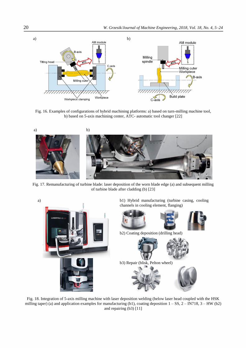
Fig. 16. Examples of configurations of hybrid machining platforms: a) based on turn-milling machine tool,
b) based on 5-axis machining center, ATC- automatic tool changer [22]
a)
b)
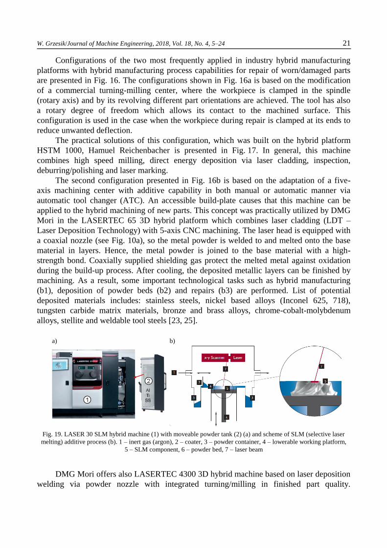
Fig. 17. Remanufacturing of turbine blade: laser deposition of the worn blade edge (a) and subsequent milling
of turbine blade after cladding (b) [23]
a)
b1) Hybrid manufacturing (turbine casing, cooling
channels in cooling element, flanging)
b2) Coating deposition (drilling head)
b3) Repair (blisk, Pelton wheel)
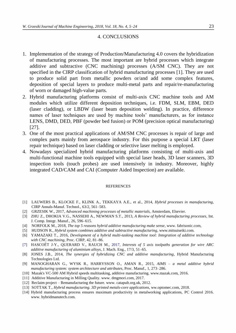
Fig. 18. Integration of 5-axis milling machine with laser deposition welding (below laser head coupled with the HSK
milling taper) (a) and application examples for manufacturing (b1), coating deposition 1 – SS, 2 – IN718, 3 – HW (b2)
and repairing (b3) [11]
W. Grzesik/Journal of Machine Engineering, 2018, Vol. 18, No. 4, 5–24 21
Configurations of the two most frequently applied in industry hybrid manufacturing
platforms with hybrid manufacturing process capabilities for repair of worn/damaged parts
are presented in Fig. 16. The configurations shown in Fig. 16a is based on the modification
of a commercial turning-milling center, where the workpiece is clamped in the spindle
(rotary axis) and by its revolving different part orientations are achieved. The tool has also
a rotary degree of freedom which allows its contact to the machined surface. This
configuration is used in the case when the workpiece during repair is clamped at its ends to
reduce unwanted deflection.
The practical solutions of this configuration, which was built on the hybrid platform
HSTM 1000, Hamuel Reichenbacher is presented in Fig. 17. In general, this machine
combines high speed milling, direct energy deposition via laser cladding, inspection,
deburring/polishing and laser marking.
The second configuration presented in Fig. 16b is based on the adaptation of a five-
axis machining center with additive capability in both manual or automatic manner via
automatic tool changer (ATC). An accessible build-plate causes that this machine can be
applied to the hybrid machining of new parts. This concept was practically utilized by DMG
Mori in the LASERTEC 65 3D hybrid platform which combines laser cladding (LDT –
Laser Deposition Technology) with 5-axis CNC machining. The laser head is equipped with
a coaxial nozzle (see Fig. 10a), so the metal powder is welded to and melted onto the base
material in layers. Hence, the metal powder is joined to the base material with a high-
strength bond. Coaxially supplied shielding gas protect the melted metal against oxidation
during the build-up process. After cooling, the deposited metallic layers can be finished by
machining. As a result, some important technological tasks such as hybrid manufacturing
(b1), deposition of powder beds (b2) and repairs (b3) are performed. List of potential
deposited materials includes: stainless steels, nickel based alloys (Inconel 625, 718),
tungsten carbide matrix materials, bronze and brass alloys, chrome-cobalt-molybdenum
alloys, stellite and weldable tool steels [23, 25].
a)
b)
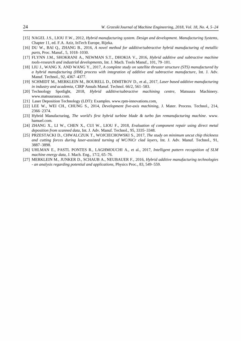
Fig. 19. LASER 30 SLM hybrid machine (1) with moveable powder tank (2) (a) and scheme of SLM (selective laser
melting) additive process (b). 1 – inert gas (argon), 2 – coater, 3 – powder container, 4 – lowerable working platform,
5 – SLM component, 6 – powder bed, 7 – laser beam
DMG Mori offers also LASERTEC 4300 3D hybrid machine based on laser deposition
welding via powder nozzle with integrated turning/milling in finished part quality.

22 W. Grzesik/Journal of Machine Engineering, 2018, Vol. 18, No. 4, 5–24
Its technological capability includes 6-sided machining performed by turning and milling
operations. The flexibility of additive manufacturing is combined with the precision of CNC
machining. DMG MORI LASER 30 SLM hybrid machine utilizes additive manufacturing
with powder bed process shown in Fig. 19. A wide range of different areas of application, in
particular creation of the filigree parts with lattice structures, internal cooling channels and
lightweight structures is possible. It allows high-precision generation of 3D parts with layer
thickness of 20 µm to 100 µm (in general from 20 µm to 150 µm [26]. The powder module
can be simply inserted into the machine, docked and used immediately. Fiber laser sources
of 400 W or up to 1kW are installed. As reported in ref. [26] the monitoring of the energy
consumption is also developed in order to achieve the energy saving by 15%. For this
purpose special machine learning algorithms are used to optimize individual toolpaths.
a) regeneration of the seal of gas compressor made of Inconel 718
b) regeneration of the atomizer shaft made of 4340 steel, clad material- stainless steel 420 LC
c) material deposition on the undersized forging (atomizer wheel) made of Ti6-4 titanium alloy
Fig. 20. Examples of repairs of different parts using LDT technique (Laser Deposition Technology) [21], 1 – worn part,
2 – part after cladding, 3 – part after machining of deposited layer
Fig. 20 presents some typical examples of remanufacturing of large, high-value parts
such as housing of a gas compressor (Inconel 718), shaft (420 SS steel) and rejected forging
with unacceptable dimensions (Ti6-4 alloy).
W. Grzesik/Journal of Machine Engineering, 2018, Vol. 18, No. 4, 5–24 23
4. CONCLUSIONS
1. Implementation of the strategy of Production/Manufacturing 4.0 covers the hybridization
of manufacturing processes. The most important are hybrid processes which integrate
additive and subtractive (CNC machining) processes (A/SM CNC). They are not
specified in the CIRP classification of hybrid manufacturing processes [1]. They are used
to produce solid part from metallic powders or/and add some complex features,
deposition of special layers to produce multi-metal parts and repair/re-manufacturing
of worn or damaged high-value parts.
2. Hybrid manufacturing platforms consist of multi-axis CNC machine tools and AM
modules which utilize different deposition techniques, i.e. FDM, SLM, EBM, DED
(laser cladding), or LBDW (laser beam deposition welding). In practice, difference
names of laser techniques are used by machine tools’ manufacturers, as for instance
LENS, DMD, DED, PBF (powder bed fusion) or POM (precision optical manufacturing)
[27].
3. One of the most practical applications of AM/SM CNC processes is repair of large and
complex parts mainly from aerospace industry. For this purpose a special LRT (laser
repair technique) based on laser cladding or selective laser melting is employed.
4. Nowadays specialized hybrid manufacturing platforms consisting of multi-axis and
multi-functional machine tools equipped with special laser heads, 3D laser scanners, 3D
inspection tools (touch probes) are used intensively in industry. Moreover, highly
integrated CAD/CAM and CAI (Computer Aided Inspection) are available.
REFERENCES
[1] LAUWERS B., KLOCKE F., KLINK A., TEKKAYA A.E., et al., 2014, Hybrid processes in manufacturing,
CIRP Annals-Manuf. Technol., 63/2, 561–583.
[2] GRZESIK W., 2017, Advanced machining processes of metallic materials, Amsterdam, Elsevier.
[3] ZHU Z., DHOKIA V.G., NASSEHI A., NEWMAN S.T., 2013, A Review of hybrid manufacturing processes, Int.
J. Comp. Integr. Manuf., 26, 596–615.
[4] NORFOLK M., 2018, The top 5 reasons hybrid additive manufacturing make sense, www. fabrisonic.com,
[5] HUDSON R., Hybrid system combines additive and subtractive manufacturing, www.mitsuiseiki.com.
[6] YAMAZAKI T., 2016, Development of a hybrid multi-tasking machine tool: Integration of additive technology
with CNC machining, Proc. CIRP, 42, 81–86.
[7] HASCOËT J-Y., QUERARD V., RAUCH M., 2017, Interests of 5 axis toolpaths generation for wire ARC
additive manufacturing of aluminium alloys, J. Mach. Eng., 17/3, 51–65.
[8] JONES J.B., 2014, The synergies of hybridizing CNC and additive manufacturing, Hybrid Manufacturing
Technologies Ltd.
[9] MANOGHARAN G., WYSK R., HARRYSSON O., AMAN R., 2015, AIMS – a metal additive hybrid
manufacturing system: system architecture and attributes, Proc. Manuf., 1, 273–286.
[10] Mazak's VC-500 AM Hybrid speeds multitasking, additive manufacturing. www.mazak.com, 2016.
[11] Additive Manufacturing in Milling Quality. www. dmgmori.com, 2017.
[12] Reclaim project – Remanufacturing the future. www. catapult.org.uk, 2012.
[13] SOTTAK T., Hybrid manufacturing. 3D printed metals-core applications, ww.optomec.com, 2018.
[14] Hybrid manufacturing process ensures maximum productivity in metalworking applications, PC Control 2016.
www. hybridmanutech.com.
24 W. Grzesik/Journal of Machine Engineering, 2018, Vol. 18, No. 4, 5–24
[15] NAGEL J.S., LIOU F.W., 2012, Hybrid manufacturing system. Design and development. Manufacturing Systems,
Chapter 11, ed. F.A. Aziz, InTech Europe, Rijeka.
[16] DU W., BAI Q., ZHANG B., 2016, A novel method for additive/subtractive hybrid manufacturing of metallic
parts, Proc. Manuf., 5, 1018–1030.
[17] FLYNN J.M., SHOKRANI A., NEWMAN S.T., DHOKIA V., 2016, Hybrid additive and subtractive machine
tools-research and industrial developments, Int. J. Mach. Tools Manuf., 101, 79–101.
[18] LIU J., WANG X. AND WANG Y., 2017, A complete study on satellite thruster structure (STS) manufactured by
a hybrid manufacturing (HM) process with integration of additive and subtractive manufacture, Int. J. Adv.
Manuf. Technol., 92, 4367–4377.
[19] SCHMIDT M., MERKLEIN M., BOURELL D., DIMITROV D., et al., 2017, Laser based additive manufacturing
in industry and academia, CIRP Annals Manuf. Technol. 66/2, 561–583.
[20] Technology Spotlight, 2018, Hybrid additive/subtractive machining centre, Matsuura Machinery.
www.matsuurausa.com.
[21] Laser Deposition Technology (LDT): Examples. www.rpm-innovations.com.
[22] LEE W., WEI CH., CHUNG S., 2014, Development five-axis machining, J. Mater. Process. Technol., 214,
2366–2374.
[23] Hybrid Manufacturing, The world's first hybrid turbine blade & turbo fan remanufacturing machine. www.
hamuel.com.
[24] ZHANG X., LI W., CHEN X., CUI W., LIOU F., 2018, Evaluation of component repair using direct metal
deposition from scanned data, Int. J. Adv. Manuf. Technol., 95, 3335–3348.
[25] PRZESTACKI D., CHWALCZUK T., WOJCIECHOWSKI S., 2017, The study on minimum uncut chip thickness
and cutting forces during laser-assisted turning of WC/NiCr clad layers, Int. J. Adv. Manuf. Technol., 91,
3887–3898.
[26] UHLMAN E., PASTL PONTES R., LAGHMOUCHI A., et al., 2017, Intelligent pattern recognition of SLM
machine energy data, J. Mach. Eng., 17/2, 65–76.
[27] MERKLEIN M., JUNKER D., SCHAUB A., NEUBAUER F., 2016, Hybrid additive manufacturing technologies
- an analysis regarding potential and applications, Physics Proc., 83, 549–559.