Embed Size (px)
Citation preview
Journal of Constructional Steel Research 100 (2014) 211–228
Contents lists available at ScienceDirect
Journal of Constructional Steel Research
Developments and advanced applications of concrete-filled steel tubular(CFST) structures: Members
Lin-Hai Han a,⁎, Wei Li a, Reidar Bjorhovde b,1
a Department of Civil Engineering, Tsinghua University, Beijing, Chinab The Bjorhovde Group, Tucson, AZ, USA
⁎ Corresponding author. Tel./fax: +86 10 62797067.E-mail addresses: [email protected], lhhanqw@g
1 Tsinghua Chair Professor.
http://dx.doi.org/10.1016/j.jcsr.2014.04.0160143-974X/© 2014 Elsevier Ltd. All rights reserved.
a b s t r a c t
a r t i c l e i n f oArticle history:Received 12 June 2013Accepted 4 April 2014Available online 13 May 2014
Keywords:Concrete-filled steel tube (CFST)MembersExperimental researchTheoretical researchDesign approachesPractical projects
Concrete-filled steel tubular (CFST) structure offers numerous structural benefits, and has been widely usedin civil engineering structures. This paper reviews the development of the family of concrete-filled steel tubularstructures to date and draws a research framework on CFST members. The research development on CFST struc-tural members in most recent years, particularly in China, is summarized and discussed. The current designapproaches from various countries are examined briefly. Some projects in China utilizing CFST members arealso introduced. Finally, some concluding remarks are made for CFST members.
© 2014 Elsevier Ltd. All rights reserved.
1. Introduction
The concrete-filled steel tubular (CFST) structure offers numerousstructural benefits, including high strength and fire resistances, favor-able ductility and large energy absorption capacities. There is also noneed for the use of shuttering during concrete construction; hence,the construction cost and time are reduced. These advantages havebeen widely exploited and have led to the extensive use of concrete-filled tubular structures in civil engineering structures.
China has seen a great deal of research and use of concrete-filledsteel tubular structures in practice. There are numbers of books pub-lished in public domain in recent years [1–6]. Some codes of practiceand local specifications were developed to provide design guidance aswell. This paper reviews the state-of-the-art for concrete-filled steeltubular structures, especially some the most recent developments inChina. Current design approaches from various countries are examinedbriefly. Some practical projects using CFST members are presented, andthe development trends are discussed.
2. Component behavior
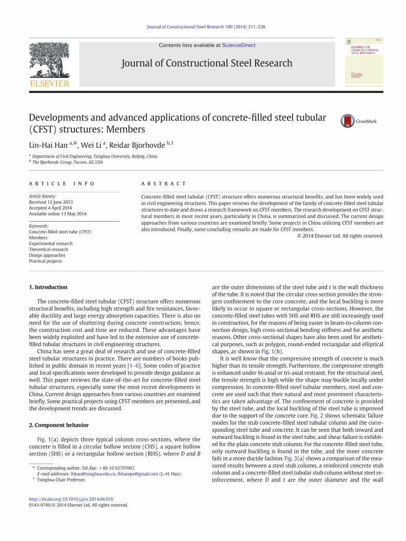
Fig. 1(a) depicts three typical column cross-sections, where theconcrete is filled in a circular hollow section (CHS), a square hollowsection (SHS) or a rectangular hollow section (RHS), where D and B
mail.com (L.-H. Han).
are the outer dimensions of the steel tube and t is the wall thicknessof the tube. It is noted that the circular cross section provides the stron-gest confinement to the core concrete, and the local buckling is morelikely to occur in square or rectangular cross-sections. However, theconcrete-filled steel tubes with SHS and RHS are still increasingly usedin construction, for the reasons of being easier in beam-to-column con-nection design, high cross-sectional bending stiffness and for aestheticreasons. Other cross-sectional shapes have also been used for aestheti-cal purposes, such as polygon, round-ended rectangular and ellipticalshapes, as shown in Fig. 1(b).
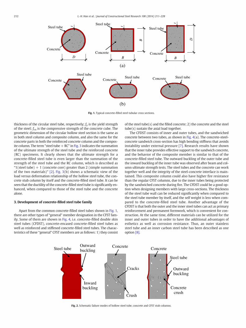
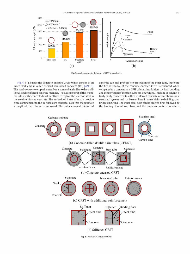
It is well know that the compressive strength of concrete is muchhigher than its tensile strength. Furthermore, the compressive strengthis enhanced under bi-axial or tri-axial restraint. For the structural steel,the tensile strength is high while the shape may buckle locally undercompression. In concrete-filled steel tubular members, steel and con-crete are used such that their natural and most prominent characteris-tics are taken advantage of. The confinement of concrete is providedby the steel tube, and the local buckling of the steel tube is improveddue to the support of the concrete core. Fig. 2 shows schematic failuremodes for the stub concrete-filled steel tubular column and the corre-sponding steel tube and concrete. It can be seen that both inward andoutward buckling is found in the steel tube, and shear failure is exhibit-ed for the plain concrete stub column. For the concrete-filled steel tube,only outward buckling is found in the tube, and the inner concretefails in amore ductile fashion. Fig. 3(a) shows a comparison of themea-sured results between a steel stub column, a reinforced concrete stubcolumn and a concrete-filled steel tubular stub columnwithout steel re-inforcement, where D and t are the outer diameter and the wall
(a)
BConcrete
D
Steel tube
t
BD
B
ConcreteConcrete
Steel tubeSteel tube t
Concrete
(b)
t
Steel tubeSteel tube Steel tube
Concrete Concrete
Fig. 1. Typical concrete-filled steel tubular cross sections.
212 L.-H. Han et al. / Journal of Constructional Steel Research 100 (2014) 211–228
thickness of the circular steel tube, respectively; fy is the yield strengthof the steel; fcu is the compressive strength of the concrete cube. Thegeometric dimension of the circular hollow steel section is the same asin both steel column and composite column, and also the same for theconcrete parts in both the reinforced concrete column and the compos-ite column. The term "steel tube+RC" in Fig. 3 indicates the summationof the ultimate strength of the steel tube and the reinforced concrete(RC) specimens. It clearly shows that the ultimate strength for aconcrete-filled steel tube is even larger than the summation of thestrength of the steel tube and the RC column, which is described as“1(steel tube) + 1 (concrete core) greater than 2 (simple summationof the two materials)” [2]. Fig. 3(b) shows a schematic view of theload versus deformation relationship of the hollow steel tube, the con-crete stub column by itself and the concrete-filled steel tube. It can beseen that the ductility of the concrete-filled steel tube is significantly en-hanced, when compared to those of the steel tube and the concretealone.
3. Development of concrete-filled steel tube family
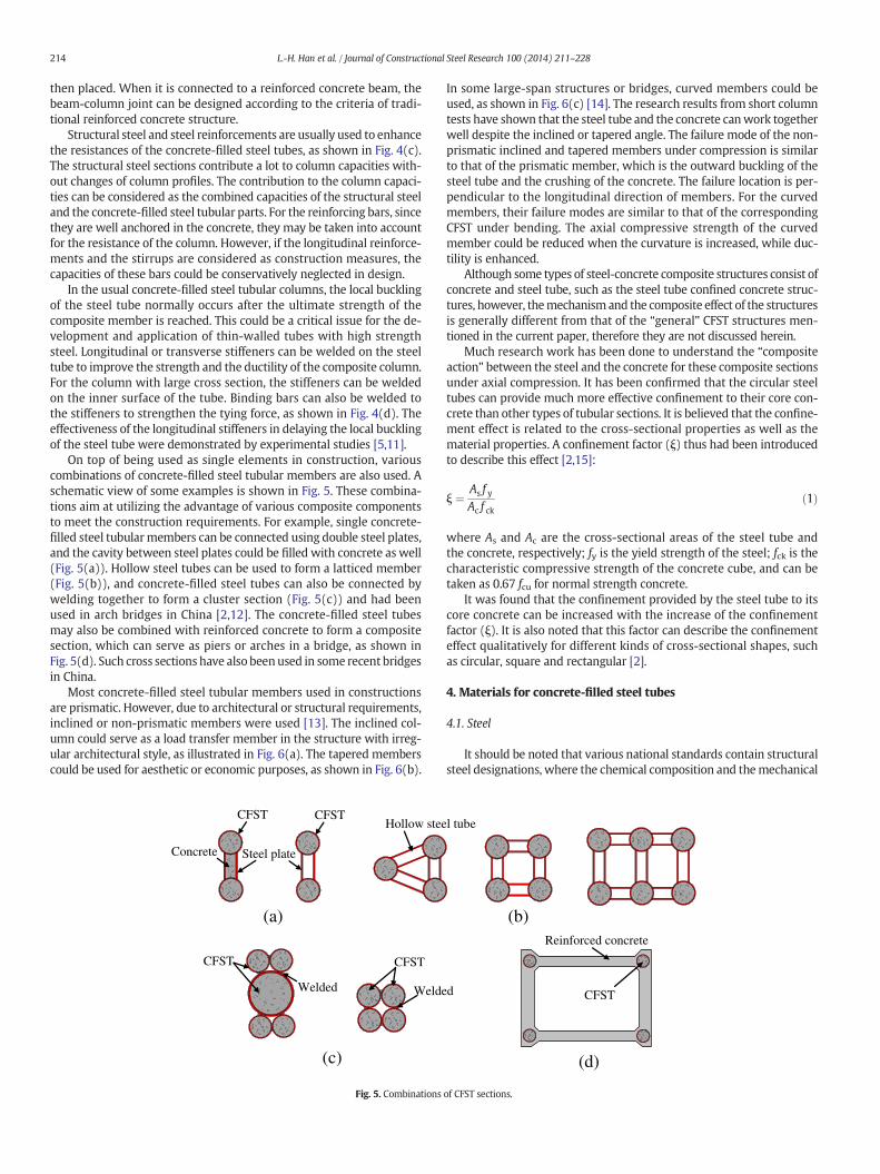
Apart from the common concrete-filled steel tubes shown in Fig. 1,there are other types of “general”member designation in the CFST fam-ily. Some of them are shown in Fig. 4, i.e. concrete-filled double skinsteel tubes (CFDST), concrete-encased concrete-filled steel tubes aswell as reinforced and stiffened concrete-filled steel tubes. The charac-teristics of these “general” CFSTmembers are as follows: 1) they consist
Steel tube ConcreOutwardbuckling
Inwardbuckling
Fig. 2. Schematic failure modes of hollow stee
of the steel tube(s) and the filled concrete; 2) the concrete and the steeltube(s) sustain the axial load together.
The CFDST consists of inner and outer tubes, and the sandwichedconcrete between two tubes, as shown in Fig. 4(a). The concrete-steel-concrete sandwich cross-section has high bending stiffness that avoidsinstability under external pressure [7]. Research results have shownthat the inner tube provides effective support to the sandwich concrete,and the behavior of the composite member is similar to that of theconcrete-filled steel tube. The outward buckling of the outer tube andthe inward buckling of the inner tubewas observed after beam and col-umn ultimate strength tests. The steel tubes and the concrete can worktogether well and the integrity of the steel-concrete interface is main-tained. This composite column could also have higher fire resistancethan the regular CFST columns, due to the inner tubes being protectedby the sandwiched concrete during fire. The CFDST could be a good op-tion when designing members with large cross-sections. The thicknessof the steel tube wall can be reduced significantly when compared tothe steel tube member by itself, and the self weight is less when com-pared to the concrete-filled steel tube. Another advantage of theCFDST is that both the outer and the inner steel tubes can act as primaryreinforcement and permanent formwork, which is convenient for con-struction. At the same time, different materials can be utilized for theinner and outer tubes in order to have the additional advantages ofesthetics as well as corrosion resistance. Thus, an outer stainlesssteel tube and an inner carbon steel tube has been described as oneoption [8].
te Concrete
Steel tube
Outwardbuckling
Concretecrush
Crush
Cracks
l tube, concrete and CFST stub columns.
0
500
1000
1500
2000
2500
3000fcu=78N/mm2
fy=363N/mm2
D × t=160 × 3.46mm
729kN
Ulti
mat
e st
reng
th (
kN)
1192kN
1921kN2057kN
Steel tube+RC
RCSteel tube CFST
(a) (b) Axial shortening
Axi
al s
tren
gth
Hollow steel
Concrete
Steel+
Concrete
CFST
0
Fig. 3. Axial compressive behavior of CFST stub column.
213L.-H. Han et al. / Journal of Constructional Steel Research 100 (2014) 211–228
Fig. 4(b) displays the concrete-encased CFSTs which consist of aninner CFST and an outer encased reinforced concrete (RC) [4,9,10].This steel-concrete compositemember is somewhat similar to the tradi-tional steel reinforced concretemember. The basic concept of thismem-ber is to use the concrete-filled steel tube to replace the I-section steel inthe steel reinforced concrete. The embedded inner tube can provideextra confinement to the in-filled core concrete, such that the ultimatestrength of the column is improved. The outer encased reinforced
(a) Concrete-filled do
Carbon steel tube
Concrete
(c) CFST with add
(b) Concrete
Conc
Reinforcement
(d) Stiffe
Concrete Steel tube
Steel
Steel tube
Concrete
Stiffener
Concrete
Steel tub
Fig. 4. General CFST
concrete can also provide fire protection to the inner tube, thereforethe fire resistance of the concrete-encased CFST is enhanced whencompared to a conventional CFST column. In addition, the local bucklingand the corrosion of the steel tube can be avoided. This kind of column isfairly easily connected to either reinforced concrete or steel beams in astructural system, and has been utilized in some high-rise buildings andbridges in China. The inner steel tube can be erected first, followed bythe binding of reinforced bars, and the inner and outer concrete is
uble skin tubes (CFDST)
itional reinforcement
-encased CFST
rete
ReinforcementInner steel tube
ned CFST
Stiffener
Stainless steel
Carbon steel Concrete
Concrete
Reinforcement
Steel tube Concrete
Steel tubee
Binding bars
cross sections.
214 L.-H. Han et al. / Journal of Constructional Steel Research 100 (2014) 211–228
then placed. When it is connected to a reinforced concrete beam, thebeam-column joint can be designed according to the criteria of tradi-tional reinforced concrete structure.
Structural steel and steel reinforcements are usually used to enhancethe resistances of the concrete-filled steel tubes, as shown in Fig. 4(c).The structural steel sections contribute a lot to column capacities with-out changes of column profiles. The contribution to the column capaci-ties can be considered as the combined capacities of the structural steeland the concrete-filled steel tubular parts. For the reinforcing bars, sincethey are well anchored in the concrete, they may be taken into accountfor the resistance of the column. However, if the longitudinal reinforce-ments and the stirrups are considered as construction measures, thecapacities of these bars could be conservatively neglected in design.
In the usual concrete-filled steel tubular columns, the local bucklingof the steel tube normally occurs after the ultimate strength of thecomposite member is reached. This could be a critical issue for the de-velopment and application of thin-walled tubes with high strengthsteel. Longitudinal or transverse stiffeners can be welded on the steeltube to improve the strength and the ductility of the composite column.For the column with large cross section, the stiffeners can be weldedon the inner surface of the tube. Binding bars can also be welded tothe stiffeners to strengthen the tying force, as shown in Fig. 4(d). Theeffectiveness of the longitudinal stiffeners in delaying the local bucklingof the steel tube were demonstrated by experimental studies [5,11].
On top of being used as single elements in construction, variouscombinations of concrete-filled steel tubular members are also used. Aschematic view of some examples is shown in Fig. 5. These combina-tions aim at utilizing the advantage of various composite componentsto meet the construction requirements. For example, single concrete-filled steel tubularmembers can be connected using double steel plates,and the cavity between steel plates could be filled with concrete as well(Fig. 5(a)). Hollow steel tubes can be used to form a latticed member(Fig. 5(b)), and concrete-filled steel tubes can also be connected bywelding together to form a cluster section (Fig. 5(c)) and had beenused in arch bridges in China [2,12]. The concrete-filled steel tubesmay also be combined with reinforced concrete to form a compositesection, which can serve as piers or arches in a bridge, as shown inFig. 5(d). Such cross sections have also beenused in some recent bridgesin China.
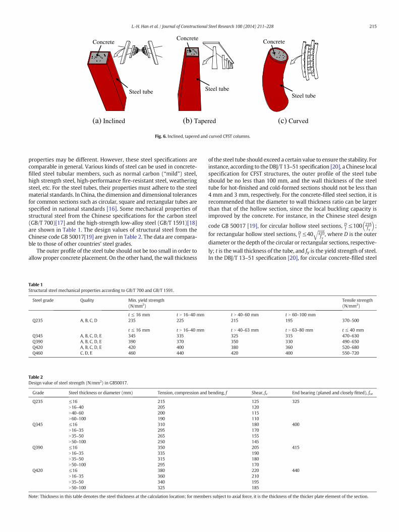
Most concrete-filled steel tubular members used in constructionsare prismatic. However, due to architectural or structural requirements,inclined or non-prismatic members were used [13]. The inclined col-umn could serve as a load transfer member in the structure with irreg-ular architectural style, as illustrated in Fig. 6(a). The tapered memberscould be used for aesthetic or economic purposes, as shown in Fig. 6(b).
CFST CFST
Welde
(c)
Hollow steeCFST
Concrete
(a)
Steel plate
Welded
CFST
Fig. 5. Combinations
In some large-span structures or bridges, curved members could beused, as shown in Fig. 6(c) [14]. The research results from short columntests have shown that the steel tube and the concrete canwork togetherwell despite the inclined or tapered angle. The failure mode of the non-prismatic inclined and tapered members under compression is similarto that of the prismatic member, which is the outward buckling of thesteel tube and the crushing of the concrete. The failure location is per-pendicular to the longitudinal direction of members. For the curvedmembers, their failure modes are similar to that of the correspondingCFST under bending. The axial compressive strength of the curvedmember could be reduced when the curvature is increased, while duc-tility is enhanced.
Although some types of steel-concrete composite structures consist ofconcrete and steel tube, such as the steel tube confined concrete struc-tures, however, themechanism and the composite effect of the structuresis generally different from that of the “general” CFST structures men-tioned in the current paper, therefore they are not discussed herein.
Much research work has been done to understand the “compositeaction” between the steel and the concrete for these composite sectionsunder axial compression. It has been confirmed that the circular steeltubes can provide much more effective confinement to their core con-crete than other types of tubular sections. It is believed that the confine-ment effect is related to the cross-sectional properties as well as thematerial properties. A confinement factor (ξ) thus had been introducedto describe this effect [2,15]:
ξ ¼ As f yAc f ck
ð1Þ
where As and Ac are the cross-sectional areas of the steel tube andthe concrete, respectively; fy is the yield strength of the steel; fck is thecharacteristic compressive strength of the concrete cube, and can betaken as 0.67 fcu for normal strength concrete.
It was found that the confinement provided by the steel tube to itscore concrete can be increased with the increase of the confinementfactor (ξ). It is also noted that this factor can describe the confinementeffect qualitatively for different kinds of cross-sectional shapes, suchas circular, square and rectangular [2].
4. Materials for concrete-filled steel tubes
4.1. Steel
It should be noted that various national standards contain structuralsteel designations, where the chemical composition and themechanical
d CFST
Reinforced concrete
(d)
l tube
(b)
of CFST sections.
(a) Inclined (c) Curved (b) Tapered
Steel tube
ConcreteConcrete
Concrete
Steel tubeSteel tube
Fig. 6. Inclined, tapered and curved CFST columns.
215L.-H. Han et al. / Journal of Constructional Steel Research 100 (2014) 211–228
properties may be different. However, these steel specifications arecomparable in general. Various kinds of steel can be used in concrete-filled steel tubular members, such as normal carbon (“mild”) steel,high strength steel, high-performance fire-resistant steel, weatheringsteel, etc. For the steel tubes, their properties must adhere to the steelmaterial standards. In China, the dimension and dimensional tolerancesfor common sections such as circular, square and rectangular tubes arespecified in national standards [16]. Some mechanical properties ofstructural steel from the Chinese specifications for the carbon steel(GB/T 700)[17] and the high-strength low-alloy steel (GB/T 1591)[18]are shown in Table 1. The design values of structural steel from theChinese code GB 50017[19] are given in Table 2. The data are compara-ble to those of other countries' steel grades.
The outer profile of the steel tube should not be too small in order toallow proper concrete placement. On the other hand, thewall thickness
Table 1Structural steel mechanical properties according to GB/T 700 and GB/T 1591.
Steel grade Quality Min. yield strength(N/mm2)
t ≤ 16 mm t N 16–40 mmQ235 A, B, C, D 235 225
t ≤ 16 mm t N 16–40 mmQ345 A, B, C, D, E 345 335Q390 A, B, C, D, E 390 370Q420 A, B, C, D, E 420 400Q460 C, D, E 460 440
Table 2Design value of steel strength (N/mm2) in GB50017.
Grade Steel thickness or diameter (mm) Tension, compression and
Q235 ≤16 215N16–40 205N40–60 200N60–100 190
Q345 ≤16 310N16–35 295N35–50 265N50–100 250
Q390 ≤16 350N16–35 335N35–50 315N50–100 295
Q420 ≤16 380N16–35 360N35–50 340N50–100 325
Note: Thickness in this table denotes the steel thickness at the calculation location; for membe
of the steel tube should exceed a certain value to ensure the stability. Forinstance, according to the DBJ/T 13–51 specification [20], a Chinese localspecification for CFST structures, the outer profile of the steel tubeshould be no less than 100 mm, and the wall thickness of the steeltube for hot-finished and cold-formed sections should not be less than4 mm and 3 mm, respectively. For the concrete-filled steel section, it isrecommended that the diameter to wall thickness ratio can be largerthan that of the hollow section, since the local buckling capacity isimproved by the concrete. For instance, in the Chinese steel design
code GB 50017 [19], for circular hollow steel sections, Dt ≤100 235
f y
� �;
for rectangular hollow steel sections, Dt ≤40ffiffiffiffiffiffi235f y
q, where D is the outer
diameter or the depth of the circular or rectangular sections, respective-
ly; t is the wall thickness of the tube, and fy is the yield strength of steel.In the DBJ/T 13–51 specification [20], for circular concrete-filled steel
Tensile strength(N/mm2)
t N 40–60 mm t N 60–100 mm215 195 370–500
t N 40–63 mm t N 63–80 mm t ≤ 40 mm325 315 470–630350 330 490–650380 360 520–680420 400 550–720
bending, f Shear, fv End bearing (planed and closely fitted), fce
125 325120115110180 400170155145205 415190180170220 440210195185
rs subject to axial force, it is the thickness of the thicker plate element of the section.
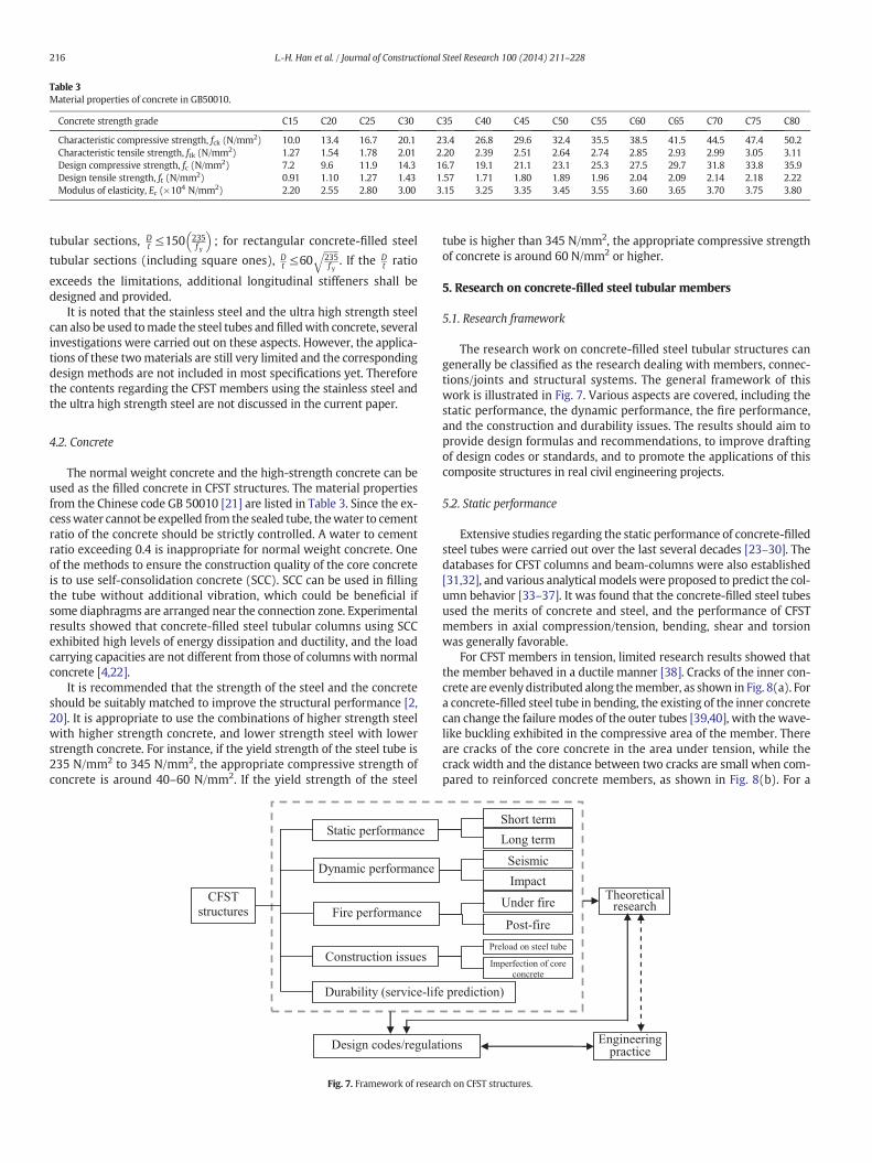
Table 3Material properties of concrete in GB50010.
Concrete strength grade C15 C20 C25 C30 C35 C40 C45 C50 C55 C60 C65 C70 C75 C80
Characteristic compressive strength, fck (N/mm2) 10.0 13.4 16.7 20.1 23.4 26.8 29.6 32.4 35.5 38.5 41.5 44.5 47.4 50.2Characteristic tensile strength, ftk (N/mm2) 1.27 1.54 1.78 2.01 2.20 2.39 2.51 2.64 2.74 2.85 2.93 2.99 3.05 3.11Design compressive strength, fc (N/mm2) 7.2 9.6 11.9 14.3 16.7 19.1 21.1 23.1 25.3 27.5 29.7 31.8 33.8 35.9Design tensile strength, ft (N/mm2) 0.91 1.10 1.27 1.43 1.57 1.71 1.80 1.89 1.96 2.04 2.09 2.14 2.18 2.22Modulus of elasticity, Ec (×104 N/mm2) 2.20 2.55 2.80 3.00 3.15 3.25 3.35 3.45 3.55 3.60 3.65 3.70 3.75 3.80
216 L.-H. Han et al. / Journal of Constructional Steel Research 100 (2014) 211–228
tubular sections, Dt ≤150 235
f y
� �; for rectangular concrete-filled steel
tubular sections (including square ones), Dt ≤60
ffiffiffiffiffiffi235f y
q. If the D
t ratio
exceeds the limitations, additional longitudinal stiffeners shall bedesigned and provided.
It is noted that the stainless steel and the ultra high strength steelcan also be used tomade the steel tubes and filledwith concrete, severalinvestigations were carried out on these aspects. However, the applica-tions of these twomaterials are still very limited and the correspondingdesign methods are not included in most specifications yet. Thereforethe contents regarding the CFST members using the stainless steel andthe ultra high strength steel are not discussed in the current paper.
4.2. Concrete
The normal weight concrete and the high-strength concrete can beused as the filled concrete in CFST structures. The material propertiesfrom the Chinese code GB 50010 [21] are listed in Table 3. Since the ex-cesswater cannot be expelled from the sealed tube, thewater to cementratio of the concrete should be strictly controlled. A water to cementratio exceeding 0.4 is inappropriate for normal weight concrete. Oneof the methods to ensure the construction quality of the core concreteis to use self-consolidation concrete (SCC). SCC can be used in fillingthe tube without additional vibration, which could be beneficial ifsome diaphragms are arranged near the connection zone. Experimentalresults showed that concrete-filled steel tubular columns using SCCexhibited high levels of energy dissipation and ductility, and the loadcarrying capacities are not different from those of columnswith normalconcrete [4,22].
It is recommended that the strength of the steel and the concreteshould be suitably matched to improve the structural performance [2,20]. It is appropriate to use the combinations of higher strength steelwith higher strength concrete, and lower strength steel with lowerstrength concrete. For instance, if the yield strength of the steel tube is235 N/mm2 to 345 N/mm2, the appropriate compressive strength ofconcrete is around 40–60 N/mm2. If the yield strength of the steel
Fig. 7. Framework of resear
tube is higher than 345 N/mm2, the appropriate compressive strengthof concrete is around 60 N/mm2 or higher.
5. Research on concrete-filled steel tubular members
5.1. Research framework
The research work on concrete-filled steel tubular structures cangenerally be classified as the research dealing with members, connec-tions/joints and structural systems. The general framework of thiswork is illustrated in Fig. 7. Various aspects are covered, including thestatic performance, the dynamic performance, the fire performance,and the construction and durability issues. The results should aim toprovide design formulas and recommendations, to improve draftingof design codes or standards, and to promote the applications of thiscomposite structures in real civil engineering projects.
5.2. Static performance
Extensive studies regarding the static performance of concrete-filledsteel tubes were carried out over the last several decades [23–30]. Thedatabases for CFST columns and beam-columns were also established[31,32], and various analytical models were proposed to predict the col-umn behavior [33–37]. It was found that the concrete-filled steel tubesused the merits of concrete and steel, and the performance of CFSTmembers in axial compression/tension, bending, shear and torsionwas generally favorable.
For CFST members in tension, limited research results showed thatthe member behaved in a ductile manner [38]. Cracks of the inner con-crete are evenly distributed along themember, as shown in Fig. 8(a). Fora concrete-filled steel tube in bending, the existing of the inner concretecan change the failure modes of the outer tubes [39,40], with the wave-like buckling exhibited in the compressive area of the member. Thereare cracks of the core concrete in the area under tension, while thecrack width and the distance between two cracks are small when com-pared to reinforced concrete members, as shown in Fig. 8(b). For a
ch on CFST structures.
(a) Tension
(c) Torsion
Steel tube Concrete
Crack
Cracks
Concrete
Steel tube
(b) Bending
Steel tubeInward
buckling
Concrete
Concrete
Steel tube
Crush
Crush
Cracks
Outwardbuckling
Cracks
Steel tube
Steel tube
Concrete
Cracks
Steel tube Concrete CFST
Steel tube
Concrete
CFST
Steel tube Concrete CFST
Fig. 8. Schematic failure modes of steel tube, concrete and CFST under tension, bending and torsion.
217L.-H. Han et al. / Journal of Constructional Steel Research 100 (2014) 211–228
concrete-filled steel tube in torsion, the compressive force is developedin the inner concrete while the tensile force in the diagonal direction isdeveloped in the steel tube. A space “truss action” is formed and the coreconcrete improves the buckling of the steel tube. For the hollow steeltube, obvious torsional buckling is exhibited when the torsion isapplied, as shown in Fig. 8(c) [33]. For the slender CFST members,experiments were conducted on long CFST columns subjected to com-plex load protocols [41]. The results showed that the CFST columns ex-hibited superior performance and the current American specificationunder-predicted the column strength.
Built-up concrete-filled steel tubular members have been used instructures such as bridges and large-span buildings. Han et al. [42] con-ducted the research on curved concrete-filled steel tubular latticedmembers to investigate the influence of variations in the tube shape, ini-tial curvature, nominal slenderness ratio, cross-sectional pattern andbrace pattern. The experimental results showed that the load-bearingcapacity, the initial stiffness and the ductility of curved latticed mem-bers are significantly increased when chord tubes are filled with con-crete. The axial compressive strength of the hollow tube specimen isonly 30%–40% of those of the corresponding concrete-filled specimen.The experimental results also demonstrated that the ultimate strengthand stiffness of the curved concrete latticed specimen decreases withthe increase of the initial curvature and the nominal slenderness ratio.
The CFSTmembers are also influenced by creep and shrinkage of theconcrete during its service life [2,43,44]. The time-dependent behaviorwas investigated in tests, and the theoretical model to account for
shrinkage and creep effects on concrete-filled steel tubular columnsunder sustained loading has been proposed [44]. As the cross sectionalprofile of the concrete-filled steel tube becomes larger, the hydrationheat and shrinkage of the core concrete becomes critical. An experimen-tal investigationwas conducted towards the hydration heat and shrink-age of concrete-filled steel tubes [45]. Self-consolidating concrete wasused in the test. It was found that at an early stage, the shrinkage ofthe concrete increased rapidly until it reached a fairly stable valueafter about 100 days. The characteristics of the temperature fieldin concrete-filled tubes are similar to that of plain concrete membersduring cement hydration. The test measuring the shrinkage of the con-crete lasted for 3 years. The results showed that due to the constraint ofthe outer tube, the shrinkage value of the concrete core in the filledtubes is only about 25–40% of that of the exposed concrete. No obviousgap was observed between the steel tube and concrete after the test.
5.3. Dynamic performance
The strength, the ductility and the hysteretic behavior are veryimportant structural aspects in seismic design. Large amounts of exper-imental and theoretical studies have been conducted on the dynamicperformance of CFST columns [2,26,29,30,46–49]. For the moment -curvature response and the lateral load versus lateral displacement rela-tionship, hysteretic models were proposed for the cyclic response basedon parametric studies, including key parameters such as axial load level,steel ratio, slenderness ratio and material strength. The predictions
Ncr
Th
To OA
T
B
N
thHeating phase
Initial loading phase
t
Cooling phase
Post-fire loading phase
C
D
E
td
No
Fig. 9. Time (t) - load (N) - temperature (T) path (Adapted from Ref. [66]).
218 L.-H. Han et al. / Journal of Constructional Steel Research 100 (2014) 211–228
of the theoretical model showed good agreement with the test results(with a difference less than 12%) [48,49]. On the other hand, as the col-umns in bridges and complex buildings may be subjected to torsionload, CFST column tests incorporating combined compression, bendingand torsional cyclic loading were conducted [50]. It was found thathysteretic curves of CFST columns under combined loadings exhibitedvery limited pinching effect. The torsion capacity of CFST columns wasreduced by the bendingmoment. The research on the low-cycle fatiguebehavior of CFST column was also conducted [51].
As the concrete-encased concrete-filled steel tubes are used in brid-ges and buildings in seismic regions, the research on the cyclic behaviorof such composite columns was conducted [10]. In general this kind ofcolumns exhibited a favorable energy dissipation capacity. The ductilityand the energy dissipation ability of the concrete-encased CFST columnsdecreased with the increase of the axial load level.
For the analytical models of CFST columns under cyclic loading,Hajjar and Tort [35], Denavit and Hajjar [37] conducted numerical stud-ies on rectangular and circular CFST structures, respectively, where the3-D fiber-based beam finite-element models were developed. The re-sults showed that this mixed finite element formulation could predictboth detailed local response and overall structural response, and couldbe utilized in the analysis of a complete structural system.
Concrete-filled steel tubular members may also be subjected toimpact loading when they are used as piers in a bridge or as exteriorcolumns in a building. Some research was conducted on this aspect[52–55]. These studies showed that CFST members in general have anexcellent impact resistance. It was found that the CFST specimen witha large confinement factor exhibited ductile behavior, while the speci-men with a small confinement factor exhibited brittle response [55].The study also found that for the specimen with a brittle failure mode,the critical failure energy increased with the increase of the axial loadlevel.
5.4. Fire performance
The fire resistance of unprotected hollow steel tubular columns inhigh-rise buildings is normally found to be less than half a hour. Forconcrete-filled steel tubular columns, the filled concrete can significant-ly increase the fire resistance. Because the heat is absorbed by the coreconcrete, the temperature in the steel tube increases much slowerthan that of the bare hollow steel tubes. Moreover, the outer tubeprovides a confinement to the core concrete during the fire exposure,the spalling of the core concrete thus can be prevented.
Numerous studies have been conducted on the fire performance ofCFST columns [56–62]. Fire resistance tests were also conducted forconcrete-filled double skin steel tubular columns [63]. For the concrete-filled steel tube, several parameters could affect the fire resistance ofthe composite column, such as the cross-sectional profile, the load eccen-tricity and the thickness of fire protection. It was found that the cross-sectional profile and thefire protection thickness had themost significantinfluence for the temperature distribution in the column. For theconcrete-filled double skin steel tube, test results showed that the tem-perature in the inner tube was less than 500 ˚C even when the tempera-ture in the outer tube was about 900 ˚C, the CFDST column has better fireendurance than the corresponding CFST column.
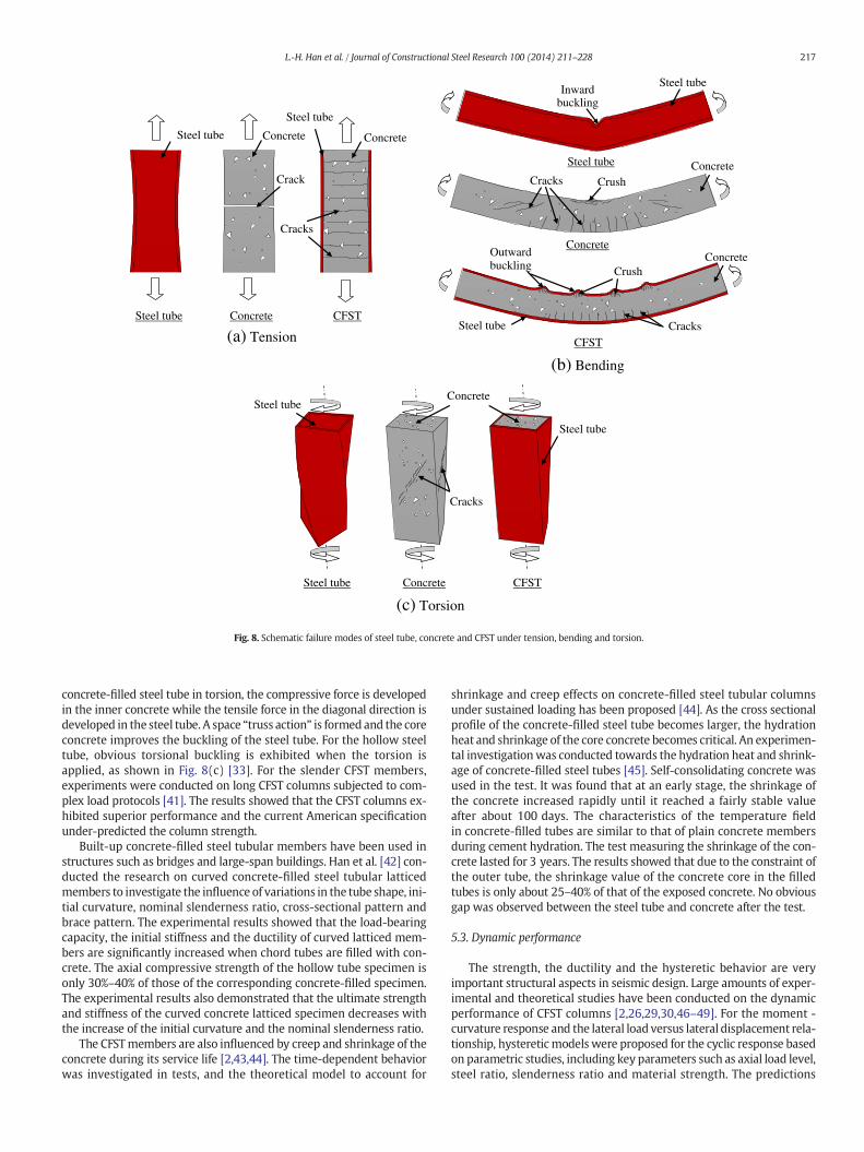
It is noted that among these studies, most experiments were carriedout under an ISO 834 standard fire [64], and the cooling phase wasusually not considered. A time-force-temperature (T-N-T) path wasproposed to illustrate the fire and the load action during an entire fireexposure [2,65,66]. The full-range loading path included four stages asshown in Fig. 9, i.e. the initial loading stage (AB) at ambient temperature(To); the heating stage (BC) with constant load (No); the cooling stage(CD) with constant load (No) and the post-fire loading phase (DE).When the temperature drops to ambient temperature (To) at time td,the load is applied till the structure fails at ultimate strength (Ncr).In Fig. 9, the temperature starts to decrease after peak temperature
(Th) at heating time (th). The specimen was loaded at the ambienttemperature, and then it was heated while the load was kept constant.After the heating, the specimen was cooled to the ambient temperatureagain, and then it was loaded until failure. Since themechanical proper-ties of steel and concrete depend on the temperature and loading histo-ries, and even when the specimen has survived the heating stage,it would still be possible to fail in the cooling stage. The proposed full-range analysis provides a reasonable approach to the evaluation of thestructural fire performance.
In practice, the fire exposed CFST column could be strengthened byplacing concrete and thin-walled steel tubes around the original dam-aged sections. Experimental results showed that all specimens behavedin a ductile manner [67]. The additional outer tube and concrete signif-icantly increased the stiffness and strength of the original specimen, andthe failuremode of the repaired specimenswas outward buckling of thesteel tube. To evaluate and repair the fire-exposed building, an evalua-tion procedure should be applied, including a damage investigation,numerical or experimental analyses and repair suggestion. The fullrange T-N-T path can be adopted in this procedure. The full-range anal-ysis has been applied in the post-fire evaluation for some real projects.It was found that this procedure can reflect the effect of a natural fire,and a more reasonable result was obtained.
5.5. Construction and durability issues
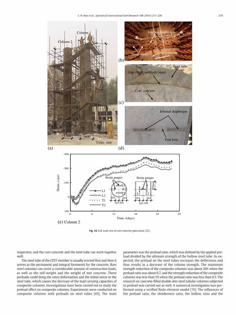
Many practicing engineers concerned about whether the concreteand steel tube could work together sufficiently to achieve the “compos-ite action” in a real column. Previously a large amount of reduced scaleexperiments were carried out, and very few can reflect the real effect ofconcrete placement. A field experiment for the concrete placement ofthe concrete-filled steel tube with circular cross section was conducted[68]. Two full-size columns were tested with SCC as the infilling, asshown in Fig. 10(a) and (b). The SCC is placed by the pump fillingmeth-od. The columnswere cut after the test, and it was shown that the com-pactness of the core concrete was very good, even for the concreteadjacent to the internal diaphragm (shown as in Fig. 10(c) and (d)).There were very few gaps between the concrete and the steel tube,and the maximum width of the gap was 0.1 mm. The test results alsoshowed that the shrinkage strain of the core concrete in the longitudinaldirection is larger than that in transverse direction (themeasured strainversus time relations of Column2were shown in Fig. 10(e)), whichmaybe due to different constraints of these two directions. In general, theconsolidation of the core concrete can be ensured by the quality controlof material, the proper methods for both the construction and the
(a)-450
-300
-150
0
1500 6 12 18 24 30
Time, t(days)
Stra
in,
()
L1
L2
T1
T2
(e) Column 2
1224
0
16001300
12540
Column 1
Column 2
Units: mm
Internal diaphragm
Vent hole
Core concrete
Steel tube
Gap (Max. width=0.1mm)
Wet concreteShear studs
Internal diaphragm
(b)
(c)
D/4
D/4 D/4
D/4
650m
m
D/4
D/4 D/4
D/4
Strain gauges Strain gauges
T1
T2L1 L2
L1 L2
(d)
Fig. 10. Full scale test of core concrete placement (Z2).
219L.-H. Han et al. / Journal of Constructional Steel Research 100 (2014) 211–228
inspection, and the core concrete and the steel tube can work togetherwell.
The steel tube of the CFSTmember is usually erected first and then itserves as the permanent and integral formwork for the concrete. Baresteel columns can resist a considerable amount of construction loads,as well as the self-weight and the weight of wet concrete. Thesepreloads could bring the extra deformation and the initial stress to thesteel tube, which causes the decrease of the load carrying capacities ofcomposite columns. Investigations have been carried out to study thepreload effect on composite columns. Experiments were conducted oncomposite columns with preloads on steel tubes [69]. The main
parameter was the preload ratio, whichwas defined by the applied pre-load divided by the ultimate strength of the hollow steel tube. As ex-pected, the preload on the steel tubes increases the deflections andthus results in a decrease of the column strength. The maximumstrength reduction of the composite columns was about 20% when thepreload ratiowas about 0.7, and the strength reduction of the compositecolumns was less than 5%when the preload ratio was less than 0.3. Theresearch on concrete-filled double skin steel tubular columns subjectedto preload was carried out as well. A numerical investigation was per-formed using a verified finite element model [70]. The influences ofthe preload ratio, the slenderness ratio, the hollow ratio and the
220 L.-H. Han et al. / Journal of Constructional Steel Research 100 (2014) 211–228
material strength on the compressive strength showed that the strengthreduction is less than 5%when the preload ratio is less than 0.2 for bothcircular and square CFDST sections.
The geometric imperfections and the residual stresses from the steeltube affect the sensitivity in local buckling. The possible imperfectionsfrom the concrete placement, such as gaps as well as cavities in theconcrete, could also affect the column performance. For CFST, the con-crete imperfection is a significant problem although the influence ofthe steel imperfection can be reduced by concrete. The investigationwas conducted on members with initial concrete imperfection [71]. Itwas found that for the CFST stub column with circumferential gapbetween tube and concrete, the strength loss of the column is lessthan 3.5% if the gap ratio (2dc/D, dc is the gap width and D is the tubediameter) is smaller than 0.05%.
The concrete-filled steel tube may also suffer from chloride corro-sion in some cases, such as in offshore structures. It is of great impor-tance to understand the mechanism and the consequences ofstructures subjected to corrosion in order to obtain more sustainablestructures. Studies were conducted on concrete-filled steel tubularstub columns and beams under long-term load and chloride corrosion[72]. Itwas found that thedecrease of theultimate strength and stiffnessis significant when concrete-filled steel tubular members are subjectedto both long-term sustained loading and chloride corrosion, since thewall thickness of the steel tube is reduced. The load sustained by thesteel tube was partially transferred to the concrete core after the lossof the tube wall, and the strength and the stiffness decrease of CFSTcolumn was smaller than its hollow steel tube counterpart. Li et al.[73] investigated the behavior of concrete-filled double skin steeltubes under the combination of preload on steel tubes, long-term loadand chloride corrosion using numerical models. Several stages wereidentified by characteristic points on the load-deformation relationship.It was found that for stub columns, the decrease of ultimate strengthand the increase of overall deformationwas presentedwhen the combi-nations of loads and environmental factors were considered.
6. Design criteria
There are a number of design codes and specifications that addressthe design of concrete-filled steel tubular members [74], such as theAIJ guide [75], the ANSI/AISC 360 [76] and the Eurocode 4 [77]. TheANSI/AISC 360 is the specification for steel structures in the UnitedStates; the Eurocode 4 is the European code for composite structuredesign; and the AIJ guide is the Japanese guide for concrete-filled steeltubular structures, respectively. In China, there are several industrialand local specifications regarding the concrete-filled steel tubular struc-tures [2], such as DBJ/T13-51 [20]. All of them are applicable for the
Table 4Scope of application for various building codes relevant to CFST columns.
Contents AIJ guide (2008)
Cross-sectional type Circular, Rectangular
Concrete specimen type Cylinder
Physical parameters Concrete strength (N/mm2) 18–90
Elastic modulus of concrete,Ec (N/mm2)
3:35� 104 � cγ24
� �2 � Fc60
� �
Yield strength of steel, fy (N/mm2) ≤590Elastic modulus of steel, Es (N/mm2) 205,000Flexural stiffness, EI EsIs + EcIc
Geometric parameters D/t (Circular) Depends on steel type
B/t (Square, rectangular) Depends on steel type
Long column definition lk/D N 12Steel ratio, or confinement ratio, orsteel contribution ratio
–
concrete-filled steel tubularmembers with circular and rectangular (in-cluding square) cross sections. The scopes of application for variouscodes are listed in Table 4 briefly. More details can be found in eachcode. For the ANSI/AISC 360 and the AIJ guide, formulas for both loadand resistance factor (limit state) design and allowable stress designare provided, the Eurocode 4 and the DBJ/T13-51 provide formulas forlimit state design.
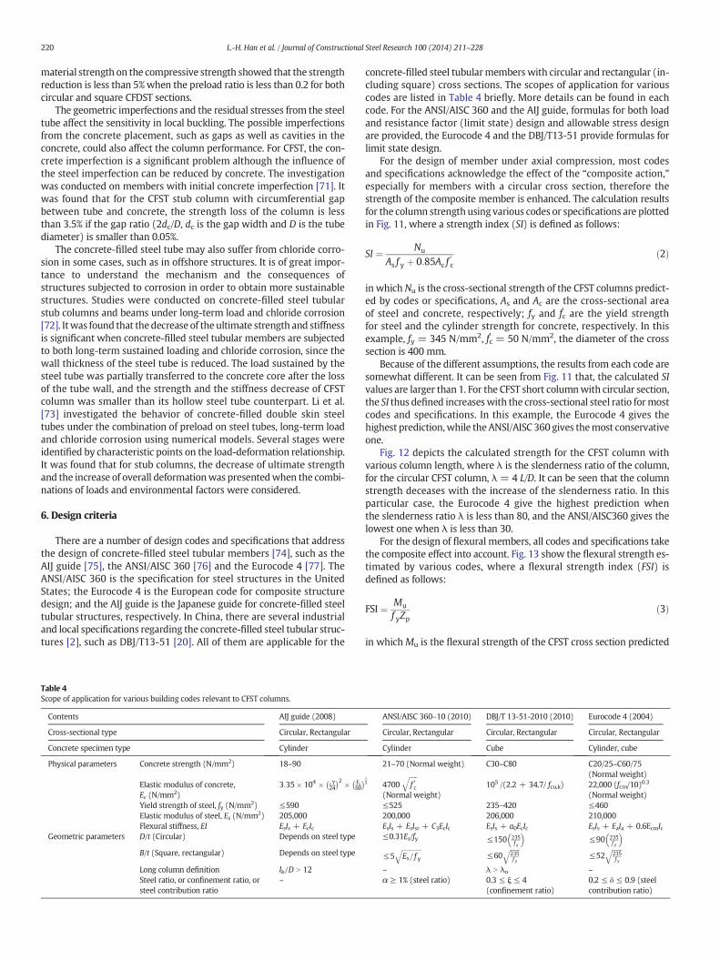
For the design of member under axial compression, most codesand specifications acknowledge the effect of the “composite action,”especially for members with a circular cross section, therefore thestrength of the composite member is enhanced. The calculation resultsfor the column strength using various codes or specifications are plottedin Fig. 11, where a strength index (SI) is defined as follows:
SI ¼ Nu
As f y þ 0:85Ac f0c
ð2Þ
in which Nu is the cross-sectional strength of the CFST columns predict-ed by codes or specifications, As and Ac are the cross-sectional areaof steel and concrete, respectively; fy and fc
' are the yield strengthfor steel and the cylinder strength for concrete, respectively. In thisexample, fy = 345 N/mm2, fc' = 50 N/mm2, the diameter of the crosssection is 400 mm.
Because of the different assumptions, the results from each code aresomewhat different. It can be seen from Fig. 11 that, the calculated SIvalues are larger than 1. For the CFST short columnwith circular section,the SI thus defined increaseswith the cross-sectional steel ratio formostcodes and specifications. In this example, the Eurocode 4 gives thehighest prediction,while theANSI/AISC 360 gives themost conservativeone.
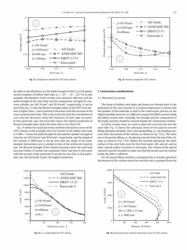
Fig. 12 depicts the calculated strength for the CFST column withvarious column length, where λ is the slenderness ratio of the column,for the circular CFST column, λ = 4 L/D. It can be seen that the columnstrength deceases with the increase of the slenderness ratio. In thisparticular case, the Eurocode 4 give the highest prediction whenthe slenderness ratio λ is less than 80, and the ANSI/AISC360 gives thelowest one when λ is less than 30.
For the design of flexural members, all codes and specifications takethe composite effect into account. Fig. 13 show the flexural strength es-timated by various codes, where a flexural strength index (FSI) isdefined as follows:
FSI ¼ Mu
f yZpð3Þ
in whichMu is the flexural strength of the CFST cross section predicted
ANSI/AISC 360–10 (2010) DBJ/T 13-51-2010 (2010) Eurocode 4 (2004)
Circular, Rectangular Circular, Rectangular Circular, Rectangular
Cylinder Cube Cylinder, cube
21–70 (Normal weight) C30–C80 C20/25–C60/75(Normal weight)
13 4700
ffiffiffiffiffif 0c
q
(Normal weight)105 /(2.2 + 34.7/ fcu,k) 22,000 (fcm/10)0.3
(Normal weight)≤525 235–420 ≤460200,000 206,000 210,000EsIs + EsIsr + C3EcIc EsIs + a0EcIc EsIs + EaIa + 0.6EcmIc≤0.31Es/fy ≤150 235
f y
� �≤90 235
f y
� �
≤5ffiffiffiffiffiffiffiffiffiffiffiffiEs= f y
q≤60
ffiffiffiffiffiffi235f y
q≤52
ffiffiffiffiffiffi235f y
q
– λ N λo –
α ≥ 1% (steel ratio) 0.3 ≤ ξ ≤ 4(confinement ratio)
0.2 ≤ δ ≤ 0.9 (steelcontribution ratio)
0.5
0.75
1
1.25
1.5
0.04 0.08 0.12 0.16 0.2
Steel ratio, α
Str
engt
h in
dex,
SI
AIJ GuideANSI/AISC360DBJ/T 13-51Eurocode4
fc'=50 N/mm2
fy=345N/mm2
D=400 mm
L=1200mm
Fig. 11. Compressive strength for CFST short column.
1
1.1
1.2
1.3
1.4
1.5
0.04 0.08 0.12 0.16 0.2
Steel ratio, α
Flex
ural
str
engt
h in
dex,
FSI
AIJ GuideANSI/AISC360DBJ/T13-51Eurocode 4
fc'=50 N/mm2
fy=345N/mm2
D=400mm
Fig. 13. Flexural strength for CFST column.
221L.-H. Han et al. / Journal of Constructional Steel Research 100 (2014) 211–228
by codes or specifications; fy is the yield strength of steel; Zp is the plasticsection modulus of hollow steel tube, Zp = (D3 − (D − 2t)3)/6. In thisexample, the diameter of the circular cross-section is 400 mm, and theyield strength of the steel tube and the compressive strength for con-crete cylinder are 345 N/mm2 and 50 N/mm2, respectively. It can beseen from Fig. 13 that the flexural strength index of the CFST cross sec-tion is higher than 1, and in general it decreases with the increase of thecross-sectional steel ratio. That is due to the fact that the contribution ofcore concrete decreases when the thickness of steel tube increases.In this particular case, the Eurocode 4 gives the highest prediction offlexural strength index when the steel ratio is less than 0.16.
Fig. 14 shows the axial load versusmoment interaction curves of theCFST column. In the example, the cross section of the hollow steel tubeisΦ 400×13mm, the yield strength of steel and the cylinder strength ofconcrete are 345 N/mm2 and 50 N/mm2, respectively, and the length ofthe column is 3000 mm. It can be seen that the shape of the load-moment interaction curve is similar to that of the reinforced concreteone. The flexural strength of the column increases when the axial loadincreases before it reaches the maximum value, and then it decreaseswith the increase of the axial load. It can also be seen that, in this partic-ular case, the Eurocode 4 gives the highest prediction.
0
2000
4000
6000
8000
10000
12000
14000
0 50 100 150 200
Slenderness ratio,
Loa
d, N
(kN
)
AIJ GuideANSI/AISC360DBJ/T 13-51Eurocode 4
fc'=50 N/mm2
fy=345N/mm2
D=400mm
=0.1
λ
α
Fig. 12. φ-λ relationship for CFST column.
7. Construction considerations
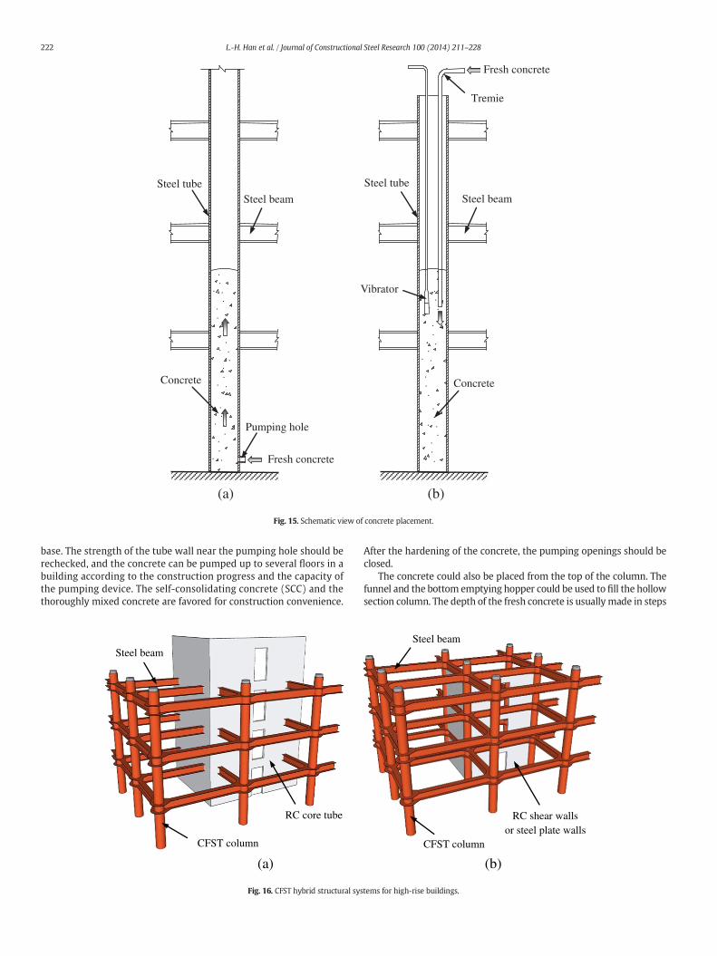
7.1. Placement of concrete
The frame of hollow steel tubes and beams are formed prior to theplacement of the core concrete. It is of great importance to ensure thatthe qualities of the materials as well as the construction process are thehighest possible, however, it is difficult to inspect thefilled concrete insidethe hollow section tube. Generally, the strength and the compactness ofthe inside concrete should be ensured despite the construction method.
In China, various ways are used to place the concrete mix into thesteel tube. Fig. 15 shows the schematic views of two typical concretefilling operation methods. One is the pump filling, i.e., by pumping con-crete from the bottom of the column, as shown in Fig. 15(a). The otherone is the gravity filling, i.e., by placing concrete from the top of the col-umn, as shown in Fig. 15(b). Before the concrete placement, the innersurface of the steel tube must be free from water, dirt and oil, and noother special surface treatment is necessary. The volume of the placedconcretemust be recorded tomake sure that the actual concrete volumeinside the tube is sufficient.
For the pump filling method, a pumping hole is usually opened atthe bottom of the columnwhen the concrete mix is pumped from the
0
3000
6000
9000
12000
0 200 400 600 800 1000
Moment, M (kNm)
Loa
d, N
(kN
)
AIJ Guide
ANSI/AISC360
DBJ/T 13-51
Eurocode 4
fc'= 50 N/mm2
fy = 345 N/mm2
D× t = 400 × 13 mm
L = 3000 mm
Fig. 14. Axial load versus moment interaction curve for CFST column.
Steel beam
Steel tubeSteel tube
Concrete
Steel beam
Concrete
Pumping hole
Tremie
Vibrator
(a) (b)
Fresh concrete
Fresh concrete
Fig. 15. Schematic view of concrete placement.
222 L.-H. Han et al. / Journal of Constructional Steel Research 100 (2014) 211–228
base. The strength of the tube wall near the pumping hole should berechecked, and the concrete can be pumped up to several floors in abuilding according to the construction progress and the capacity ofthe pumping device. The self-consolidating concrete (SCC) and thethoroughly mixed concrete are favored for construction convenience.
Steel beam
RC core tube
CFST column
(a)
Fig. 16. CFST hybrid structural sys
After the hardening of the concrete, the pumping openings should beclosed.
The concrete could also be placed from the top of the column. Thefunnel and the bottom emptying hopper could be used to fill the hollowsection column. The depth of the fresh concrete is usually made in steps
CFST column
RC shear wallsor steel plate walls
Steel beam
(b)
tems for high-rise buildings.
CFST column
Steel beam
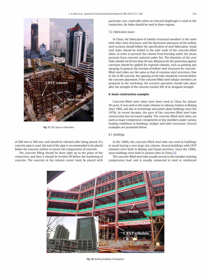
Fig. 17. SEG plaza in Shenzhen.
223L.-H. Han et al. / Journal of Constructional Steel Research 100 (2014) 211–228
of 300 mm to 500 mm, and should be vibrated after being placed. If aconcrete pipe is used, the end of the pipe is recommended to be placedbelow the concrete surface to ensure the compactness of concrete.
The concrete filling should be done right up to the plane of theconnection, and then it should be leveled off before the hardening ofconcrete. The concrete at the column corner must be placed with
Fig. 18. Ruifeng build
particular care, especially when an internal diaphragm is used in theconnection. Air holes should be used in these regions.
7.2. Fabrication issues
In China, the fabrication of tubular structural members is the samewith other steel structures, and the dimension tolerances of the hollowsteel sections should follow the specification of steel fabrication. Smallvent holes should be drilled in the tube walls of the concrete-filledtubes, in order to prevent the column from bursting under the steampressure from concrete material under fire. The diameter of the ventholes should not be less than 20mm.Measures for the protection againstcorrosion should be applied for exposed columns, such as painting andspraying. In general, the erection of hollow steel structures for concrete-filled steel tubes are the same as that of common steel structures. Dueto the in-fill concrete, the opening of the tube should be covered beforethe concrete placement. If the concrete-filled steel tubular members areprepared in the workshop, the erection operation should take placeafter the strength of the concrete reaches 50% of its designed strength.
8. Some construction examples
Concrete-filled steel tubes have been used in China for almost50 years. It was used as the main columns in subway stations in Beijingsince 1966, and also in workshops and power plant buildings since the1970s. In recent decades, the pace of the concrete-filled steel tubeconstruction has increased rapidly. The concrete-filled steel tubes areused as major compressive components or key members under variousloading conditions in buildings, bridges and other structures. Severalexamples are presented below.
8.1. Buildings
In the 1980s, the concrete-filled steel tube was used in buildingsto avoid having a very large size column. Several buildings with CFSTcolumns were built in Beijing and Fujian province. Since the 1990s,more buildings were built in various cities in China [2].
The concrete-filled steel tube usually served as themember resistingcompressive load, and is usually connected to steel or reinforced
CFST column
Steel beam
ing in Hangzhou.
CFST column
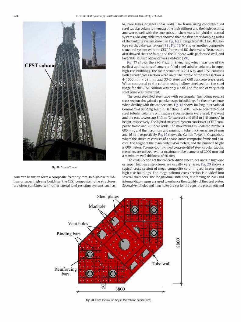
Fig. 19. Canton Tower.
224 L.-H. Han et al. / Journal of Constructional Steel Research 100 (2014) 211–228
concrete beams to form a composite frame system. In high-rise build-ings or super high-rise buildings, the CFST composite frame structuresare often combined with other lateral load resisting systems such as
Reinforcingbars
Steel plates
Binding bars
Vent holes
880
Manhole
50
Fig. 20. Cross section for mega
RC core tubes or steel shear walls. The frame using concrete-filledsteel tubular columns integrates the high stiffness and thehigh ductility,and works well with the core tubes or shear walls in hybrid structuralsystems. Shaking table tests showed that the first order damping ratiosof the building system shown in Fig. 16(a) range from 0.03 to 0.035 be-fore earthquake excitations [78]. Fig. 16(b) shows another compositestructural system with the CFST frame and RC shear walls. Tests resultsalso showed that the frame and the RC shear walls performed well, andfavorable seismic behavior was exhibited [79].
Fig. 17 shows the SEG Plaza in Shenzhen, which was one of theearliest applications of concrete-filled steel tubular columns in superhigh-rise buildings. The main structure is 291.6 m, and CFST columnswith circular cross section were used. The profile of the steel section isΦ 1600 mm × 28 mm, and Q345 steel and C60 concrete were used.When compared to the column using hollow steel section, the steelusage for the CFST column was only a half, and the use of very thicksteel plate was prevented.
The concrete-filled steel tube with rectangular (including square)cross section also gained a popular usage in buildings, for the conveniencewhen dealing with the connections. Fig. 18 shows Ruifeng InternationalCommercial Building built in Hanzhou in 2001, where concrete-filledsteel tubular columns with square cross sections were used. The westand the east towers are 84.3 m (24 storeys) and 55.5 m (15 storeys) inheight, respectively. The hybrid structural system consists of a CFST com-posite frame and RC shear walls. The maximum CFST column profile is600 mm, and the maximum and minimum tube thicknesses are 28 mmand 16mm, respectively. Fig. 19 shows the Canton Tower in Guangzhou,where the structure consists of a space lattice composite frame and a RCcore. The height of the main body is 454 meters, and the pinnacle heightis 600 meters. Twenty-four inclined concrete-filled steel circular tubularmembers are utilized, with a maximum tube diameter of 2000 mm anda maximumwall thickness of 50 mm.
The cross sections of the concrete-filled steel tubes used in high-riseor super high-rise structures are usually very large. Fig. 20 shows atypical cross section of mega composite column used in one superhigh-rise buildings. The mega column cross section is divided intoseveral chambers. The longitudinal stiffeners, reinforcing tie bars andinternal diaphragms are used to enhance the stability of the steel plates.Several vent holes andman holes are set for the concrete placement and
8800
0
Tube wall
CFST column (units: mm).
Concrete-filled steel tube
Fig. 21. CFST used in bridges.
CFST
Steelplate
Concrete
Fig. 22.Wangcang East River Bridge.
CFSTRC
Fig. 23. Zhaohua Jiali
225L.-H. Han et al. / Journal of Constructional Steel Research 100 (2014) 211–228
the installation. Usually shear connectors should be used for memberswith large cross sections to ensure a proper load transfer betweensteel and concrete.
8.2. Bridges
Concrete-filled steel tubular members have been applied in manytypes of bridges, such as arch bridges, cable stayed bridges, suspensionbridges, and truss bridges. CFST members can serve as piers, bridgetowers and arches, and they can also be used in the bridge deck system.Fig. 21 depicts the usage of CFST members in various bridge structures.
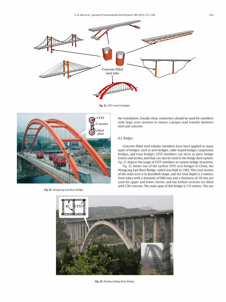
Fig. 22 shows one of the earliest CFST arch bridges in China, theWangcang East River Bridge, which was built in 1992. The cross sectionof the main arch is in dumbbell shape, and the total depth is 2 meters.Steel tubes with a diameter of 800 mm and a thickness of 10 mm areused for upper and lower chords, and the hollow sections are filledwith C30 concrete. The main span of this bridge is 115 meters. The use
ng River Bridge.
(a) (b)
CFST columns
RC beam
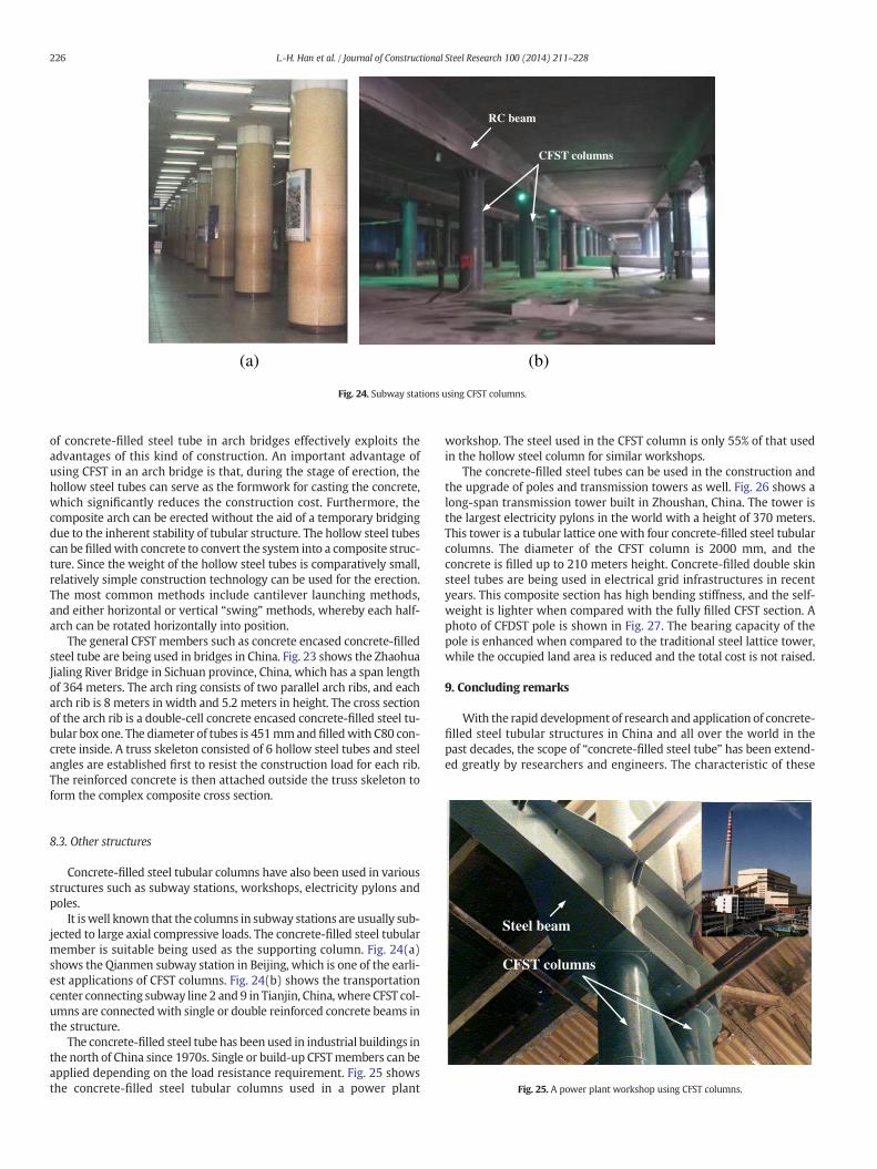
Fig. 24. Subway stations using CFST columns.
226 L.-H. Han et al. / Journal of Constructional Steel Research 100 (2014) 211–228
of concrete-filled steel tube in arch bridges effectively exploits theadvantages of this kind of construction. An important advantage ofusing CFST in an arch bridge is that, during the stage of erection, thehollow steel tubes can serve as the formwork for casting the concrete,which significantly reduces the construction cost. Furthermore, thecomposite arch can be erected without the aid of a temporary bridgingdue to the inherent stability of tubular structure. The hollow steel tubescan be filledwith concrete to convert the system into a composite struc-ture. Since the weight of the hollow steel tubes is comparatively small,relatively simple construction technology can be used for the erection.The most common methods include cantilever launching methods,and either horizontal or vertical “swing” methods, whereby each half-arch can be rotated horizontally into position.
The general CFST members such as concrete encased concrete-filledsteel tube are being used in bridges in China. Fig. 23 shows the ZhaohuaJialing River Bridge in Sichuan province, China, which has a span lengthof 364 meters. The arch ring consists of two parallel arch ribs, and eacharch rib is 8 meters in width and 5.2 meters in height. The cross sectionof the arch rib is a double-cell concrete encased concrete-filled steel tu-bular box one. The diameter of tubes is 451mmand filledwith C80 con-crete inside. A truss skeleton consisted of 6 hollow steel tubes and steelangles are established first to resist the construction load for each rib.The reinforced concrete is then attached outside the truss skeleton toform the complex composite cross section.
CFST columns
Steel beam
Fig. 25. A power plant workshop using CFST columns.
8.3. Other structures
Concrete-filled steel tubular columns have also been used in variousstructures such as subway stations, workshops, electricity pylons andpoles.
It iswell known that the columns in subway stations are usually sub-jected to large axial compressive loads. The concrete-filled steel tubularmember is suitable being used as the supporting column. Fig. 24(a)shows the Qianmen subway station in Beijing, which is one of the earli-est applications of CFST columns. Fig. 24(b) shows the transportationcenter connecting subway line 2 and 9 in Tianjin, China, where CFST col-umns are connectedwith single or double reinforced concrete beams inthe structure.
The concrete-filled steel tube has been used in industrial buildings inthe north of China since 1970s. Single or build-up CFSTmembers can beapplied depending on the load resistance requirement. Fig. 25 showsthe concrete-filled steel tubular columns used in a power plant
workshop. The steel used in the CFST column is only 55% of that usedin the hollow steel column for similar workshops.
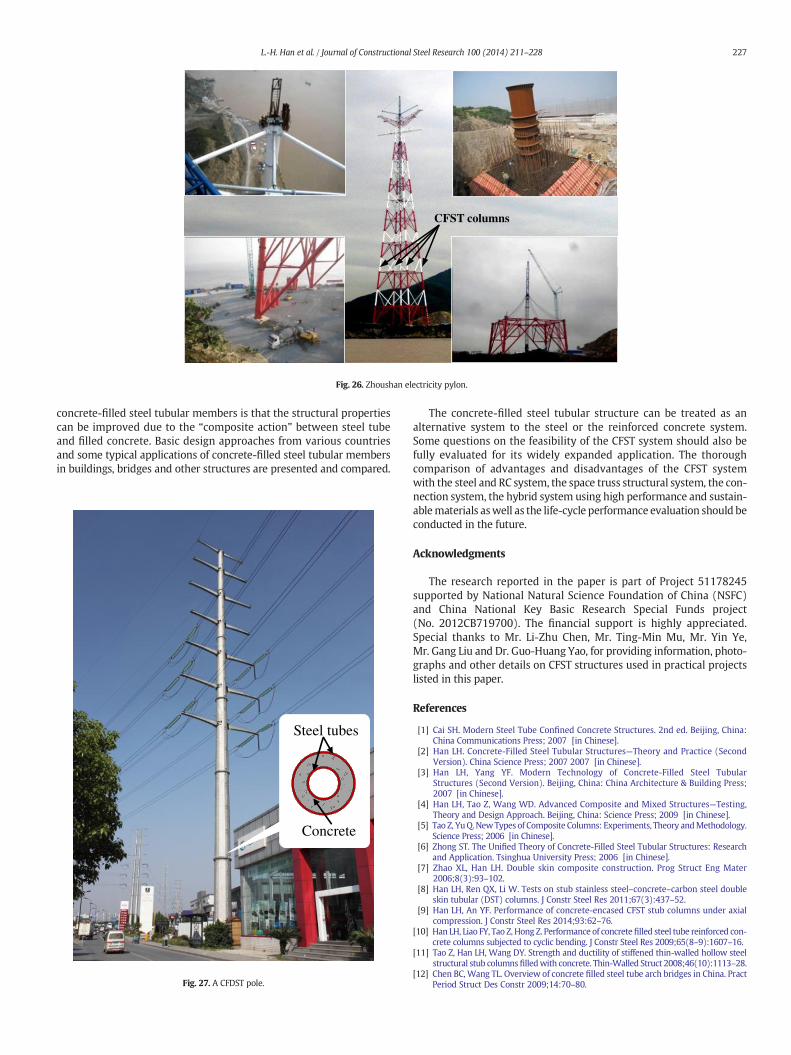
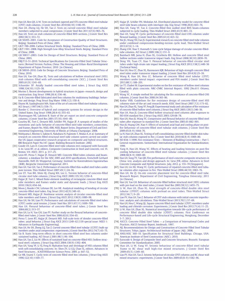
The concrete-filled steel tubes can be used in the construction andthe upgrade of poles and transmission towers as well. Fig. 26 shows along-span transmission tower built in Zhoushan, China. The tower isthe largest electricity pylons in the world with a height of 370 meters.This tower is a tubular lattice onewith four concrete-filled steel tubularcolumns. The diameter of the CFST column is 2000 mm, and theconcrete is filled up to 210 meters height. Concrete-filled double skinsteel tubes are being used in electrical grid infrastructures in recentyears. This composite section has high bending stiffness, and the self-weight is lighter when compared with the fully filled CFST section. Aphoto of CFDST pole is shown in Fig. 27. The bearing capacity of thepole is enhanced when compared to the traditional steel lattice tower,while the occupied land area is reduced and the total cost is not raised.
9. Concluding remarks
With the rapid development of research and application of concrete-filled steel tubular structures in China and all over the world in thepast decades, the scope of “concrete-filled steel tube” has been extend-ed greatly by researchers and engineers. The characteristic of these
CFST columns
Fig. 26. Zhoushan electricity pylon.
227L.-H. Han et al. / Journal of Constructional Steel Research 100 (2014) 211–228
concrete-filled steel tubular members is that the structural propertiescan be improved due to the “composite action” between steel tubeand filled concrete. Basic design approaches from various countriesand some typical applications of concrete-filled steel tubular membersin buildings, bridges and other structures are presented and compared.
Steel tubes
Concrete
Fig. 27. A CFDST pole.
The concrete-filled steel tubular structure can be treated as analternative system to the steel or the reinforced concrete system.Some questions on the feasibility of the CFST system should also befully evaluated for its widely expanded application. The thoroughcomparison of advantages and disadvantages of the CFST systemwith the steel and RC system, the space truss structural system, the con-nection system, the hybrid system using high performance and sustain-ablematerials aswell as the life-cycle performance evaluation should beconducted in the future.
Acknowledgments
The research reported in the paper is part of Project 51178245supported by National Natural Science Foundation of China (NSFC)and China National Key Basic Research Special Funds project(No. 2012CB719700). The financial support is highly appreciated.Special thanks to Mr. Li-Zhu Chen, Mr. Ting-Min Mu, Mr. Yin Ye,Mr. Gang Liu and Dr. Guo-Huang Yao, for providing information, photo-graphs and other details on CFST structures used in practical projectslisted in this paper.
References
[1] Cai SH. Modern Steel Tube Confined Concrete Structures. 2nd ed. Beijing, China:China Communications Press; 2007 [in Chinese].
[2] Han LH. Concrete-Filled Steel Tubular Structures—Theory and Practice (SecondVersion). China Science Press; 2007 2007 [in Chinese].
[3] Han LH, Yang YF. Modern Technology of Concrete-Filled Steel TubularStructures (Second Version). Beijing, China: China Architecture & Building Press;2007 [in Chinese].
[4] Han LH, Tao Z, Wang WD. Advanced Composite and Mixed Structures—Testing,Theory and Design Approach. Beijing, China: Science Press; 2009 [in Chinese].
[5] Tao Z, YuQ.NewTypes of Composite Columns: Experiments, Theory andMethodology.Science Press; 2006 [in Chinese].
[6] Zhong ST. The Unified Theory of Concrete-Filled Steel Tubular Structures: Researchand Application. Tsinghua University Press; 2006 [in Chinese].
[7] Zhao XL, Han LH. Double skin composite construction. Prog Struct Eng Mater2006;8(3):93–102.
[8] Han LH, Ren QX, Li W. Tests on stub stainless steel–concrete–carbon steel doubleskin tubular (DST) columns. J Constr Steel Res 2011;67(3):437–52.
[9] Han LH, An YF. Performance of concrete-encased CFST stub columns under axialcompression. J Constr Steel Res 2014;93:62–76.
[10] Han LH, Liao FY, Tao Z, Hong Z. Performance of concretefilled steel tube reinforced con-crete columns subjected to cyclic bending. J Constr Steel Res 2009;65(8–9):1607–16.
[11] Tao Z, Han LH, Wang DY. Strength and ductility of stiffened thin-walled hollow steelstructural stub columnsfilledwith concrete. Thin-Walled Struct 2008;46(10):1113–28.
[12] Chen BC, Wang TL. Overview of concrete filled steel tube arch bridges in China. PractPeriod Struct Des Constr 2009;14:70–80.
228 L.-H. Han et al. / Journal of Constructional Steel Research 100 (2014) 211–228
[13] Han LH, Ren QX, LiW. Tests on inclined, tapered and STS concrete-filled steel tubular(CFST) stub columns. J Constr Steel Res 2010;66(10):1186–95.
[14] Han LH, Zheng LQ, He SH, Tao Z. Tests on curved concrete filled steel tubularmembers subjected to axial compression. J Constr Steel Res 2011;67(6):965–76.
[15] Han LH. Tests on stub columns of concrete-filled RHS sections. J Constr Steel Res2002;58(3):353–72.
[16] GB 50205–2001. Code for Acceptance of Construction Quality of Steel Structures.Beijing: Standard Press of China; 2001.
[17] GB/T 700–2006. Carbon Structural Steels. Beijing: Standard Press of China; 2006.[18] GB/T 1591–2008. High Strength Low Alloy Structural Steels. Beijing: Standard Press
of China; 2008.[19] GB 50017–2003. Code for Design of Steel Structures. Beijing: Standard Press of
China; 2003.[20] DBJ/T13-51-2010. Technical Specifications for Concrete-Filled Steel Tubular Struc-
tures (Revised Version. Fuzhou, China: The Housing and Urban–Rural DevelopmentDepartment of Fujian Province; 2010 [in Chinese].
[21] GB 50010–2010. Code for Design of Concrete Structures. Beijing: Standard Press ofChina; 2010.
[22] Han LH, Yao GH, Zhao XL. Tests and calculations of hollow structural steel (HSS)stub columns filled with self-consolidating concrete (SCC). J Constr Steel Res2005;61(9):1241–69.
[23] Schneider SP. Axially loaded concrete-filled steel tubes. J Struct Eng ASCE1998;124(10):1125–38.
[24] Morino S. Recent developments in hybrid structures in Japan—research, design andconstruction. Eng Struct 1998;20(4):336–46.
[25] Uy B. Concrete-filled fabricated steel box columns for multistorey buildings: behav-iour and design. Prog Struct Eng Mater 1998;1(2):150–8.
[26] ShamsM, Saadeghvaziri MA. State of the art of concrete-filled steel tubular columns.ACI Struct J 1997;94(5):558–71.
[27] Roeder C. Overview of hybrid and composite systems for seismic design in theUnited States. Eng Struct 1998;20(4–6):355–63.
[28] Shanmugam NE, Lakshmi B. State of the art report on steel-concrete compositecolumns. J Constr Steel Res 2001;57(10):1041–80.
[29] Gourley BC, Tort C, Denavit MD, Schiller PH, Hajjar JF. A synopsis of studies of themonotonic and cyclic behavior of concrete-filled steel tube members, connections,and frames, Report No. NSEL-008, NSEL Report Series. Department of Civil and Envi-ronmental Engineering, University of Illinois at Urbana-Champaign; 2008.
[30] Nishiyama I, Morino S, Sakino K, Nakahara H, Fujimoto T, Mukai A, et al. Summary ofresearch on concrete-filled structural steel tube column system carried out underthe US–Japan cooperative research program on composite and hybrid structures.BRI Research Paper No.147. Japan: Building Research Institute; 2002.
[31] Goode CD, Lam D. Concrete-filled steel tube columns-test compared with Eurocode4. In: Leon RT, et al, editors. Composite Construction in Steel and Concrete, vol. VI.Reston, VA: ASCE; 2011. p. 317–25.
[32] Leon RT, Perea T, Hajjar JF, Denavit MD. Concrete filled tubes columns and beam-columns: a database for the AISC 2005 and 2010 specifications. Festschrift GerhardHanswille, Heft 20. Wuppertal, Germany: Institute fur Konstruktiven Ingenieurbau(IKIB), Bergische Universitat Wuppertal; 2011.
[33] Han LH, Yao GH, Tao Z. Performance of concrete-filled thin-walled steel tubes underpure torsion. Thin-Walled Struct 2007;45(1):24–36.
[34] Lee ET, Yun BH, Shim HJ, Chang KH, Lee G. Torsion behavior of concrete-filledcircular steel tube columns. J Struct Eng ASCE 2009;135(10):1250–8.
[35] Hajjar JF, Tort C. Mixed finite-element modeling of rectangular concrete-filled steeltube members and frames under static and dynamic loads. J Struct Eng ASCE2010;136(6):654–64.
[36] Moon J, Roeder CW, Lehman DE, Lee HE. Analytical modeling of bending of circularconcrete-filled steel tubes. Eng Struct 2012;42(9):349–61.
[37] Denavit MD, Hajjar JF. Nonlinear seismic analysis of circular concrete-filled steeltube members and frames. J Struct Eng ASCE 2012;138(9):1089–98.
[38] Han LH, He SH, Liao FY. Performance and calculations of concrete filled steel tubes(CFST) under axial tension. J Constr Steel Res 2011;67(11):1699–709.
[39] Han LH. Flexural behaviour of concrete-filled steel tubes. J Constr Steel Res2004;60(2):313–37.
[40] Han LH, Lu H, Yao GH, Liao FY. Further study on the flexural behaviour of concrete-filled steel tubes. J Constr Steel Res 2006;62(6):554–65.
[41] Perea T, Leon RT, Hajjar JF, Denavit MD. Full-scale tests of slender concrete-filledtubes: axial behavior. J Struct Eng ASCE 2013:1249–62 [139 special issue: NEES 1:Advances in Earthquake Engineering].
[42] Han LH, He SH, Zheng LQ, Tao Z. Curved concrete filled steel tubular (CCFST) built-upmembers under axial compression: experiments. J Constr Steel Res 2012;74(7):63–75.
[43] Uy B. Static long-term effects in short concrete-filled steel box columns undersustained loading. ACI Struct J 2001;98(1):96–104.
[44] Han LH, Tao Z, Liu W. Effects of sustained load on concrete-filled HSS (hollow struc-tural steel) columns. J Struct Eng ASCE 2004;130(9):1392–404.
[45] Han LH, Yang YF, Li YJ, Feng B. Hydration heat and shrinkage of HSS columns filledwith self-consolidating concrete. In: Shen ZY, Li GQ, Chan SL, editors. Advances inSteel Structures. , ICASS'05Elsevier Science Press; 2005. p. 647–52.
[46] Ge HB, Usami T. Cyclic tests of concrete filled steel box columns. J Struct Eng ASCE1996;122(10):1169–77.
[47] Hajjar JF, Schiller PH, Molodan AA. Distributed plasticity model for concrete-filledsteel tube beam-columns with interlayer slip. Eng Struct 1998;20(8):663–76.
[48] Han LH, Yang YF, Tao Z. Concrete-filled thin walled steel RHS beam-columnssubjected to cyclic loading. Thin-Walled Struct 2003;41(9):801–33.
[49] Han LH, Yang YF. Cyclic performance of concrete-filled steel CHS columns underflexural loading. J Constr Steel Res 2005;61(4):423–52.
[50] Nie JG,Wang YH, Fan JS. Experimental research on concrete filled steel tube columnsunder combined compression-bending-torsion cyclic load. Thin-Walled Struct2013;67(6):1–14.
[51] Zhang GW, Xiao Y, Kunnath S. Low-cycle fatigue damage of circular concrete-filled-tube columns. ACI Struct J 2009;106(2):151–9.
[52] Bambach MR, Jama H, Zhao XL, Grzebieta RH. Hollow and concrete filled steelhollow sections under transverse impact loads. Eng Struct 2008;30(10):2859–70.
[53] Deng YH, Tuan CY, Xiao Y. Flexural behavior of concrete-filled circular steeltubes under high-strain rate impact loading. J Struct Eng ASCE 2012;138(3):449–56[Technical Note].
[54] Han LH, Hou CC, Zhao XL, Rasmussen KJR. Behaviour of high-strength concrete filledsteel tubes under transverse impact loading. J Constr Steel Res 2014;92:25–39.
[55] Wang R, Han LH, Hou CC. Behavior of concrete filled steel tubular (CFST)members under lateral impact: experiment and FEA model. J Constr Steel Res2013;80(1):188–201.
[56] Lie TT, Chabot M. Experimental studies on the fire resistance of hollow steel columnsfilled with plain concrete. NRC-CNRC Internal Report; 1992 [No.611 Ottawa,Canada].
[57] Wang YC. A simple method for calculating the fire resistance of concrete-filled CHScolumns. J Constr Steel Res 2000;54:365–86.
[58] Kodur VKR. Guidelines for fire resistance design of concrete-filled steel HSScolumns-state-of-the-art and research needs. KSSC Steel Struct 2007;7(3):173–82.
[59] Han LH, ZhaoXL, Yang YF, Feng JB. Experimental study and calculation offire resistanceof concrete-filled hollow steel columns. J Struct Eng ASCE 2003;129(3):346–56.
[60] Han LH, Huo JS. Concrete-filled hollow structural steel columns after exposure toISO-834 standard fire. J Struct Eng ASCE 2003;129:68–78.
[61] Han LH, Huo JS, Wang YC. Compressive and flexural behavior of concrete filled steeltubes after exposure to standard fire. J Constr Steel Res 2005;61:882–901.
[62] Huo JS, Huang GW, Xiao Y. Effects of sustained axial load and cooling phase on post-fire behaviour of concrete-filled steel tubular stub columns. J Constr Steel Res2009;65(8–9):1664–76.
[63] Lu H, Han LH, Zhao XL. Testing of self-consolidating concrete-filled double skin tubu-lar stub columns exposed to fire. J Constr Steel Res 2010;66(8–9):1069–80.
[64] ISO 834–1:1999. Fire-resistance Tests— Elements of Building Construction — Part 1.General requirements. Switzerland: International Organization for Standardization;1999.
[65] Yang H, Han LH, Wang YC. Effects of heating and loading histories on post-firecooling behaviour of concrete-filled steel tubular columns. J Constr Steel Res2008;66(8–9):1069–80.
[66] Han LH, Song TY, Tan QH. Fire performance of steel-concrete composite structures inChina: test, analysis and design approach. In: Liew JYR, editor. Advances in SteelConcrete Composite and Hybrid Structures; July, 2012. p. 155–70 [Singapore].
[67] Han LH, Lin XK, Wang YC. Cyclic performance of repaired concrete-filled steel tubu-lar columns after exposure to fire. Thin-Walled Struct 2006;44(10):1063–76.
[68] Han LH, He ZJ. On-site concrete placement test for concrete-filled steel tube.Research Report. Department of Civil Engineering, Tsinghua University; 2011[in Chinese].
[69] Han LH, Yao GH. Behaviour of concrete-filled hollow structural steel (HSS) columnswith pre-load on the steel tubes. J Constr Steel Res 2003;59(12):1455–75.
[70] Li W, Han LH, Zhao XL. Axial strength of concrete-filled double skin steeltubular (CFDST) columns with preload on steel tubes. Thin-Walled Struct2012;56(7):9–20.
[71] Liao FY, Han LH, Tao Z. Behavior of CFST stub columns with initial concrete imperfec-tion: analysis and calculations. Thin-Walled Struct 2013;70(1):57–69.
[72] Han LH, Hou C,Wang QL. Square concrete filled steel tubular (CFST) members underloading and chloride corrosion: Experiments. J Constr Steel Res 2012;71(4):11–25.
[73] Li W, Han LH, Zhao XL. Numerical investigation towards life-cycle performance ofconcrete filled double skin tubular (CFDST) columns. First Conference onPerformance-based and Life-cycle Structural Engineering, Hongkong, December5–7; 2012.
[74] ASCCS: Concrete Filled Steel Tubes — a Comparison of International Codes andPractices. ASCCS Seminar Report, Innsbruck; 1997.
[75] AIJ. Recommendations for Design and Construction of Concrete Filled Steel TubularStructures. Tokyo, Japan: Architectural Institute of Japan (AIJ); 2008.
[76] ANSI/AISC 360–10. Specification for Structural Steel Buildings. Chicago, USA:American Institute of Steel Construction (AISC); 2010.
[77] Eurocode 4. Design of Composite Steel and Concrete Structures. Brussels: EuropeanCommittee for Standardization; 2005.
[78] Han LH, Li W, Yang YF. Seismic behaviour of concrete-filled steel tubularframe to RC shear wall high-rise mixed structures. J Constr Steel Res2009;65(5):1249–60.
[79] Liao FY, Han LH, Tao Z. Seismic behaviour of circular CFST columns and RC shear wallmixed structures: experiments. J Constr Steel Res 2009;65(8–9):1582–96.