Embed Size (px)
Citation preview
Vol. 47 No. 2 2014 87Copyright © 2014 The Society of Chemical Engineers, Japan
Journal of Chemical Engineering of Japan, Vol. 47, No. 2, pp. 87–108, 2014
Review of Retro�tting Distillation Columns Using Thermally Coupled Distillation Sequences and Dividing Wall Columns to Improve Energy E�ciency
Nguyen Van Duc Long and Moonyong LeeSchool of Chemical Engineering, Yeungnam University, Gyeongsan 712-749, South Korea
Keywords: Debottlenecking, Dividing Wall Column, Process Integration, Process Intensification, Retrofit, Thermally Coupled Distillation Column
Distillation is a common energy-intensive process. Accordingly, it is the �rst process to be addressed to improve the en-ergy e�ciency over both the short- and long-term. Recent studies and industrial applications have proven that advanced process integration and process intensi�cation techniques such as the use of a thermally coupled distillation sequence (TCDS) and a dividing wall column (DWC) require the lowest amount of energy for the separation of mixtures into pure product streams. This paper reviews some energy-e�cient distillation technologies that can be used in a retro�t design. The research on and implementation of retro�ts using a TCDS and DWC are reviewed. This report proposes coupled schemes as alternatives to using a Petlyuk column that do not have the classical problem of controlling the vapor trans-fer from one column to another and have not previously been proposed for retro�ts. These schemes are expected to make signi�cant contributions to improving the energy e�ciency and mitigating CO2 emission in the retro�tting of dis-tillation systems. The authors evaluated a solution for retro�tting azeotropic and extractive distillation systems. Various issues such as the constraints, techno-economic analysis, controllability, and operability are discussed brie�y to provide more insight into the application of TCDS and DWC technologies in the retro�t.
Introduction
Distillation, a thermal separation method, is one of the most important separation technologies in the chemical processing industry. Nevertheless, despite its many well-known advantages and widespread use, its significant energy requirements are a major drawback, because distillation can generate more than 50% of the plant operating cost (Kiss and Bildea, 2011). Furthermore, saving energy in this area has become an important issue from an environmental or CO2-mitigation standpoint, because the huge amount of energy consumed in the distillation has a large impact on greenhouse gas emissions (Matsuda et al., 2012). One inno-vative solution for reducing the total annualized cost (TAC), which includes both operating and capital costs, is the use of advanced process-integration and process-intensifica-tion techniques, such as the implementation of a thermally coupled distillation sequence (TCDS) and a dividing wall column (DWC) (Tedder and Rudd, 1978a, 1978b, 1978c; Fidkowski and Królikowski, 1986, 1987, 1990; Kaibel, 1987; Triantafyllou and Smith, 1992; Kim, 2002; Olujić et al., 2003; Hwang et al., 2008; Olujić et al., 2008, 2009; Asprion and Kaibel, 2010; Long and Lee, 2012a). In particular, a DWC is one of the best examples of a proven process intensifica-tion technology in distillation, because it has significantly
lower investment and operating costs while also reducing the amount of equipment required and the carbon footprint (Kiss and Suszwalak, 2012). According to Schultz et al. (2002), the DWC will become a standard distillation tool in the next 50 years, with an estimated 350 industrial applica-tions by 2015 (Yildirim et al., 2011).
Retrofits of distillation systems focus on the more efficient reuse of existing equipment to increase profit. When car-rying out a retrofit study, retrofit models are essential for fixing the existing distillation design. The most straightfor-ward designs are grass-roots designs, because they allow the most freedom to choose the design options and size of the equipment. The design of a retrofit must attempt to work within the constraints of existing equipment (Smith, 2005). The retrofit of distillation columns is carried out more often than the installation of new equipment, because distillation is an energy-intensive process that requires considerable capital investment (Gadalla et al., 2003). Retrofit projects comprised 70–80% of capital investment projects in the processing industry at the end of the 1980 s (Liu and Jobson, 2004a).
Two main approaches are adopted for the design of distil-lation system retrofits to increase the throughput (Liu and Jobson, 2004a):(1) replacing existing internals with high-capacity and/or
high-efficiency internals and(2) revamping the process by improving the utilization of
existing equipment and making relatively minor modi-fications, including adjusting the operating conditions, adding equipment, etc.
Received on April 23, 2013; accepted on August 20, 2013DOI: 10.1252/jcej.13we067Correspondence concerning this article should be addressed to M. Lee (E-mail address: [email protected]).
Journal Review
88 Journal of Chemical Engineering of Japan
Most distillation retrofit practices emphasize column in-ternals that not only promote separation, but also govern the column hydraulic performance (Amminudin and Smith, 2001). The retrofit of existing columns, such as the replace-ment of existing trays or packings with effective alternatives, is a frequent option because the user companies strive to increase production with minimum investment. Currently, vacuum applications are dominated by structured packings, whereas trays are normally used in high-pressure applica-tions (above 5 bar; Olujić et al., 2009). In addition, random packings can find favorable applications in the complete operating range. To cope with the ever growing demand for capacity, all three families of vapor–liquid contactors have been subjected to intensive research and development in recent years (Schultes, 2003; Kashani et al., 2005; Weiland et al., 2005; Jödecke et al., 2006, 2007; Olujić, 2007; Penciak et al., 2006; Darakchiev and Semkov, 2008). One excellent review (Olujić et al., 2009) provided a comprehensive over-view of the equipment trends in distillation covering current column internals. On the other hand, the use of better inter-nals in retrofitted distillation columns is not the only design option, nor is it always the most cost effective (Liu and Jobson, 2004a). In some cases, this does not improve the en-ergy efficiency of the system and can subsequently prevent a large increase in capacity (Manley, 1998b). Furthermore, in the case where the column already has a high-efficiency
internal, the potential for increasing the capacity by replac-ing the existing column internal with a new one is limited. This paper focuses on revamping the process to improve the utilization of existing equipment and making relatively minor modifications, including adjusting the operating con-ditions, adding equipment, and rearranging the existing columns into a complex sequence.
Most research and review papers published thus far fo-cused on new designs of TCDSs and DWCs. An excellent review (Dejanović et al., 2010) gives a comprehensive over-view of DWCs covering both the theoretical description and patent area, whereas another excellent review (Yildirim et al., 2011) examined the current industrial applications of DWCs and related research activities, including column configuration, design, modeling, and control issues. Fur-thermore, the applications of DWCs for azeotropic, extrac-tive, and reactive distillation were highlighted. The present paper provides a complete overview of promising retrofit design options for distillation systems including single- and multiple-column cases. The work focuses on design options that increase the effectiveness while utilizing the existing shells and internals, rather than simply replacing the in-ternals. This paper also reviews the research on and imple-mentation of retrofits using process integration, TCDSs, and DWCs. Coupled schemes were proposed as alternatives to using a Petlyuk column to improve the energy efficiency in
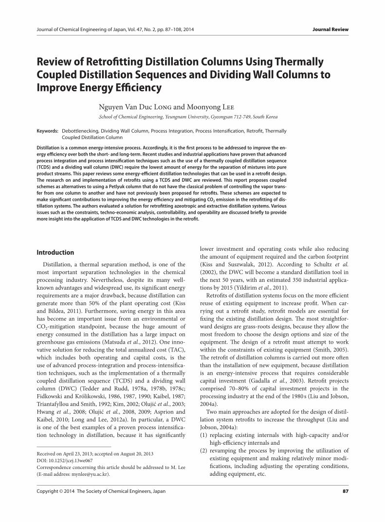
Fig. 1 Promising technologies for the retrofit of a single column
Vol. 47 No. 2 2014 89
a retrofit. Furthermore, the authors examined a solution for the retrofit of azeotropic and extractive distillation. Finally, the constraints, technical analysis, economic analysis, con-trollability, and operability in the retrofit are discussed brief-ly.
1. Promising Column Con�gurations for Retro�ts
1.1 Single-column caseTo improve the energy efficiency, the heat integration
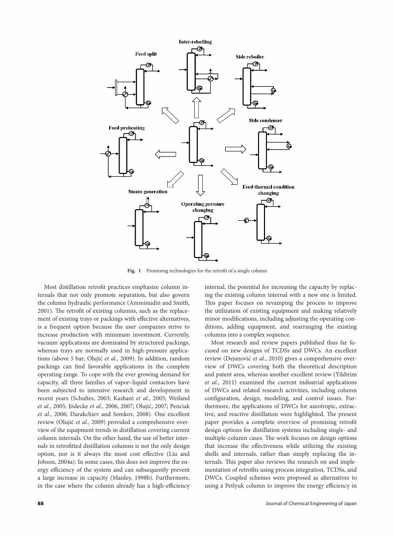
concept was first introduced approximately 70 years ago (Jana, 2010). The basic idea of the heat integration approach is that the hot process streams are heat-exchanged with cold process streams. Figure 1 shows promising technologies for the retrofit of a single column, such as a heat pump, self-heat recuperation technology, feed splitting and feed preheating, inter-reboiling, a side reboiler or a side condenser, changing the thermal conditions of the feed, and changing the operat-ing pressure.1.1.1 Heat pump Distillation has relatively low thermo-dynamic efficiency (Kim, 2012; Kiss et al., 2012), requiring the input of high-quality energy in the reboiler to perform a separation task. At the same time, a similar amount of heat at a lower temperature is given off in the condenser. Several heat pump concepts have been proposed to improve the energy efficiency of distillation columns. The vapor compression (VC) heat pump uses a working fluid that is
evaporated at the condenser, compressed to a higher (satura-tion) temperature, condensed in the reboiler, and cooled by expansion over a throttle valve to a (saturation) temperature below the condenser temperature (Bruinsma and Spoelstra, 2010). The choice of working fluid is an important degree of freedom in the design. An industrial example of VC is the ethylene–ethane separation using propylene as the working fluid (Zimmerman and Walzl, 2009). In cases in which the distillate vapor cannot be compressed, VC is the only option in some novel heat pump systems. In addition, VC is par-ticularly beneficial when dealing with corrosive and fouling compounds (Göktun, 1995).
The mechanical vapor recompression (MVR) heat pump is applied widely to the separation of mixtures with similar boiling points. The overhead vapor is pressurized using a compressor to such a level that it can be condensed at a higher temperature to supply sufficient heat to the reboiler. This leads to a major decrease in the energy requirements of the reboiler and condenser (Moser and Schnitzer, 1985; Ranade and Chao, 1990; Mizsey and Fonyo, 1992; Annakou and Mizsey, 1995; Long and Lee, 2013a). The use of me-chanical compression as a heat pump is economical mainly for separating low-relative-volatility mixtures, where small compression ratios and consequently small compressor du-ties are required because of the small temperature differ-ence between the top and bottom of the column (De Rijke, 2007). The advantages of this technique over VC are that the
Fig. 1 Promising technologies for the retrofit of a single column (continued)
90 Journal of Chemical Engineering of Japan
condenser in a MVR heat pump is smaller and that the tem-perature increase is approximately 5 K lower, because heat is exchanged only once. This results in higher thermodynamic efficiency (Bruinsma and Spoelstra, 2010).
The thermal vapor recompression (TVR) heat pump is a variant of the MVR heat pump in which the compressor is replaced by a steam ejector as the work input mechanism (Kiss et al., 2012). TVR has been implemented widely in in-dustry because of the advantages of the steam ejector (Feng and Berntsson, 1997). The steam ejector uses the Venturi ef-fect to obtain mechanical energy from steam injection into a special variable-diameter pipeline. This makes TVR a robust design with reduced capital and maintenance expenditure, because there are no rotating pieces involved (Fonyo and Benkö, 1998; Perry and Green, 1999; Kiss et al., 2012). On the other hand, the input steam is mixed with the distillate to generate the required pressure, so TVR is used mostly for systems producing water as the top product (Chen and Sun, 1997).
In a bottom flashing heat pump, the bottom stream from the column is divided into two streams: the final product stream and another that is expanded by a valve to decrease its temperature and allow heat exchange with the top stream before being recompressed to the column pressure (Fonyo et al., 1995; Long and Lee, 2013a). Fonyo et al. (1995) used this system to separate i-C4 and n-C4, whereas Long and Lee (2013a) combined this technique with a bottom dividing wall column (BDWC) to integrate the debutanizer and de-isobutanizer and reported remarkable energy savings.1.1.2 Self-heat recuperation technology In heat pumps, only the heat recovery duty of the reboiler in the distilla-tion column has been considered extensively, while the fate of the heat introduced during preheating has not been well recognized. In contrast, self-heat recuperation technology uses both latent and sensible heat in the process through the use of a compressor (Kansha et al., 2009, 2013; Matsuda et al., 2011a). Recently, Kansha et al. (2010) developed a novel integrated process module based on self-heat recuperation that facilitated heat circulation for use in distillation pro-cesses. By dividing the distillation processes among two modules, i.e., heat circulation and distillation modules, the heat of condensation and the cooling heat were recuperated by compressors and exchanged with the heat of vaporization and the heating heat through the use of heat exchangers in each module, without additional heat. This self-heat re-cuperation technology facilitates the recirculation of both latent and sensible heat in a process and helps reduce the energy consumption of that process through the use of com-pressors and self-heat exchangers (Kansha et al., 2010).
This technology can be used not only in grass-roots cases, but also in retrofit cases, and it has been considered in a range of processing industries (Long and Lee, 2013c). This is a promising technology when the problem is associated with binary mixture separation or when the column should not be integrated with other columns in sequence. With the ex-isting column, new heat exchangers and compressors can be installed, while the number of trays and the diameter of the
column are fixed. More pipe work will also be needed for the equipment links. From a technique point of view, these stud-ies can be accomplished easily in a short modification time.1.1.3 Feed splitting and feed preheating The thermal conditions of the feed can be altered to reduce the reboiler duty through heat exchange with the bottom product or with any other low-grade heat sources available. The ef-ficiency associated with using feed preheating to provide a portion of the thermal energy given to the feed reduces the reboiler duty (Liebert, 1993; Deshmukh et al., 2005). Splitting the feed into two streams and preheating only one fraction of the feed stream makes it is possible to improve the feed preheating efficiency up to 100% (Wankat and Kes-sler, 1993; Fidkowski and Agrawal, 1995). Soave and Feliu (2002) proposed the use of a steady-state simulator to deter-mine iteratively the appropriate split fraction to save energy (up to 50%) in industrial distillation towers.1.1.4 Inter-reboiling To minimize energy consumption, the bottom liquid product can be subcooled while inter-reboiling the bottom section of the column (Manley, 1998a; Long and Lee, 2012b). Manley applied inter-reboiling to improve the natural gas liquid recovery (NGL) performance, particularly to the deethanizer and depropanizer. This heat effect is particularly significant when the feed contains sig-nificant amounts of heavy components such as butanes and gasoline in the feed to a conventional NGL deethanizer distillation column. The draw and return stages for a par-tial inter-reboiler are on the same stage. Compared to an NGL deethanizer without an inter-reboiler, the system with inter-reboiling can reduce the hot utility by 26%. Manley also found that the draw temperature can be significantly reduced by requiring more theoretical stages than disclosed between the inter-reboiler draw and return stages. Increas-ing the number of stages between the draw and return stages reduces the temperature to which the hot bottom product may be cooled, increases the inter-reboiler duty, and reduces the reboiler duty.1.1.5 Side reboiler or side condenser Thermal inte-gration of a distillation column through the use of side exchangers also improves the exergetic efficiency of the column (Bandyopadhyay, 2007). For subambient distilla-tion, a significant decrease in energy consumption can be achieved by incorporating side condensers and side reboil-ers (Lynd and Grethlein, 1986; Kleinberg, 1987; Aguirre et al., 1997).
The use of a side reboiler or side cooler can also allow the throughput of a distillation column to increase (Liu and Jobson, 2004b). Side reboilers and side coolers can be used to change the vapor and liquid flows within a column sec-tion to utilize the area available more uniformly. The liquid and vapor traffic in the bottommost section of the column can be reduced using a side reboiler, and the traffic to the underutilized stages between the side-reboiler and feed will increase. Therefore, this process modification increases the uniformity of area utilization throughout the column sec-tion. A side reboiler will reduce the vapor and liquid traffic below the tray where the side reboiler is placed and increase
Vol. 47 No. 2 2014 91
the vapor and liquid traffic above the tray. Similarly, a side cooler will reduce the vapor and liquid traffic on the trays above it and increase the vapor and liquid traffic below it.1.1.6 Changing the feed thermal conditions The ther-mal conditions of the feed have a strong influence (Liu and Jobson, 2004b) on the processing capacity of an existing distillation column. This is particularly true for columns performing difficult separations. This discussion focuses on distillation columns with a single feed and only two prod-ucts, but the ideas can also be applied to more complex columns.
A methanol plant that utilizes two distillation columns to purify methanol in its separation section was retrofitted (Demirel, 2006). The suggested retrofits consisted of an ad-ditional side condenser at stage 4 and feed preheating for column 1, as well as two side reboilers at stages 87 and 92 for column 2. The effectiveness of the retrofits was assessed using the improved column grand composite curves and exergy loss profiles as well as by performing an approxi-mate economic analysis. After the retrofits, the actual and minimum vapor flow profiles became closer. In addition, the difference between the ideal and actual profiles of the en-thalpies in the columns’ grand composite curves decreased. The reductions in the total exergy losses ranged from 21.5 to 41.3%, which resulted in considerable savings in the available energy losses. The thermodynamic efficiencies also increased considerably. Therefore, the columns operate with fewer thermodynamic imperfections.1.1.7 Changing the operating pressure In a retrofit de-sign, design engineers often want to increase the throughput of an existing distillation column. Among the operating parameters, pressure is very important (Liu and Jobson, 1999). The operating pressure has a complex influence on the distillation performance; it affects the relative volatility between the components, molar vapor flow rates, flooding limitations, and vapor density.
Many studies have reported that increasing the pres-sure can decrease the diameter of a distillation column for a given separation (Liu and Jobson, 1999). Winkle (1967) stated that the vapor volume increases with decreasing pres-sure, and larger-diameter columns are needed to handle the increase in vapor volume. This increase in column size increases the investment cost. Kister (1992) reported that one of the favorable effects of increasing the column pres-sure is that it increases the vapor density and vapor handling capacity. This leads to major decreases in the column di-ameter and capital cost under vacuum, as well as to smaller reductions up to pressures of 50 to 150 psia (3.4 to 10.2 bar). Humphrey and Keller (1997) suggested that at higher pressures and temperatures, the vapor pressures increase and the viscosities decrease, which leads to higher efficiency and vapor capacity as well as a lower column diameter.
Other studies reported that decreasing the pressure can increase the capacity of a distillation column (Liu and Jobson, 1999). Capps (1993) found that for high-pressure systems, a decrease in the operating pressure allows an increase in the feed rate. This occurs because the relative
volatility and flooding capacity increase. Castillo and Dhole (1995) examined the ethylene cold-end process and suggest-ed that the throughput of the columns in the process could be increased when the operating pressure of the demetha-nizer was decreased from 3,500 to 3,100 kPa.
Liu and Jobson (1999) provided a clear and quantitative picture of the effect of pressure on the throughput of an existing distillation column. When the operating pressure is less than approximately 3 bar, increasing the pressure can increase the throughput of the existing column. When pres-sure is greater than approximately 7 bar, a decrease in the pressure can increase the throughput. Moreover, when the pressure is in an intermediate range, pressure changes have little effect on the throughput.
1.2 Multiple-column caseCurrently, process intensification is considered the main
trend for improving process performance. Process inten-sification aims to reduce the number of equipment units through the innovative design of multifunctional equip-ment, leading to reduced investment cost and significant energy savings (Rong and Turunen, 2006). For a distillation system, the thermal coupling technique provides a new mechanism for retrofitting the traditional simple column configuration through the principle of process intensifica-tion (Errico et al., 2007). This occurs through the elimina-tion of the condenser, reboiler, or both in the traditional simple column configuration using thermal coupling to provide simultaneous mass and heat transfer between the different tasks in the separation sequence. Therefore, the thermal coupling technique provides a unique approach for intensifying the traditional simple column configuration and has several advantages: a) a decrease in the number of the heat exchangers, b) an improved separation efficiency, and c) the potential to save both energy and capital costs.
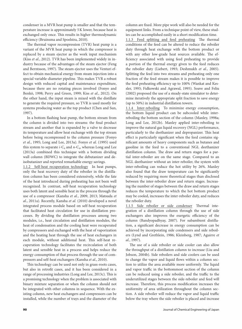
Fig. 2 Schematic diagram of the (a) direct sequence and (b) indirect sequence
92 Journal of Chemical Engineering of Japan
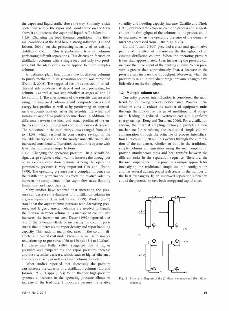
1.2.1 Prefractionator arrangement The direct and indi-rect conventional distillation sequences for ternary distilla-tion can be employed to separate a three-component feed into the pure products, as illustrated in Figures 2(a) and (b), respectively. Every distillation column has a reboiler and a condenser. The number of product flows in the col-umns is always the same, two. On the other hand, in a more novel distillation scheme, i.e., in a prefractionator scheme, as illustrated in Figure 3, there is one extra product flow, which is known as a side stream, in the second column of the column sequence (Malinen and Tanskanen, 2009). This prefractionator arrangement allows improved control and operation, since control of the external flows from the reboiler and condenser of the prefractionator column is facile. The prefractionator configuration is advantageous for conventional distillation schemes and provides better energy performance (Amminudin and Smith, 2001; Poth et al., 2004).1.2.2 Side stripper or side rectifier and Petlyuk column A TCDS can be built by implementing two interconnecting streams (one in the vapor phase and the other in the liquid phase) between the two columns. Such systems have been studied for the separation of ternary mixtures and have been shown to provide significant energy savings with respect to both the conventional direct and indirect distillation se-quences. The three most widely analyzed thermally coupled systems are the sequence with a side rectifier, the sequence with a side stripper, and a fully thermally coupled system (or Petlyuk column), which are illustrated in Figures 4(a), (b), and 5, respectively (Glinos et al., 1986; Fidkowski and Kró-likowski, 1990; Triantafyllou and Smith, 1992; Hernández and Jiménez, 1996; Jiménez et al., 2003).
Of the above possible thermal coupling arrangements, the side stripper and side rectifier have been used widely in re-finery distillation and cryogenic air separation, respectively (Seidel, 1935; Watkins, 1979; Amminudin et al., 2001). The Petlyuk column provides a fully interconnected structure with two thermal couplings that result in vapor interconnec-tions flowing back and forth between the columns (Hernán-dez et al., 2005). These sequences provide energy savings of up to 30% over the conventional direct and indirect distillation sequences (Tedder and Rudd, 1978a; Alatiqi and Luyben, 1985; Triantafyllou and Smith, 1992; Finn, 1993; Hernández and Jiménez, 1996; Hernández and A. Jiménez, 1999; Blancarte-Palacios et al., 2003).
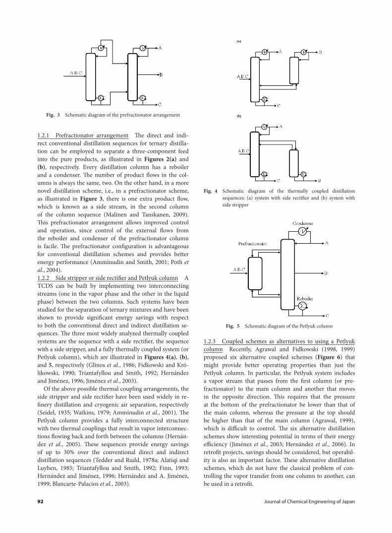
1.2.3 Coupled schemes as alternatives to using a Petlyuk column Recently, Agrawal and Fidkowski (1998, 1999) proposed six alternative coupled schemes (Figure 6) that might provide better operating properties than just the Petlyuk column. In particular, the Petlyuk system includes a vapor stream that passes from the first column (or pre-fractionator) to the main column and another that moves in the opposite direction. This requires that the pressure at the bottom of the prefractionator be lower than that of the main column, whereas the pressure at the top should be higher than that of the main column (Agrawal, 1999), which is difficult to control. The six alternative distillation schemes show interesting potential in terms of their energy efficiency (Jiménez et al., 2003; Hernández et al., 2006). In retrofit projects, savings should be considered, but operabil-ity is also an important factor. These alternative distillation schemes, which do not have the classical problem of con-trolling the vapor transfer from one column to another, can be used in a retrofit.
Fig. 3 Schematic diagram of the prefractionator arrangement
Fig. 4 Schematic diagram of the thermally coupled distillation sequences: (a) system with side rectifier and (b) system with side stripper
Fig. 5 Schematic diagram of the Petlyuk column
Vol. 47 No. 2 2014 93
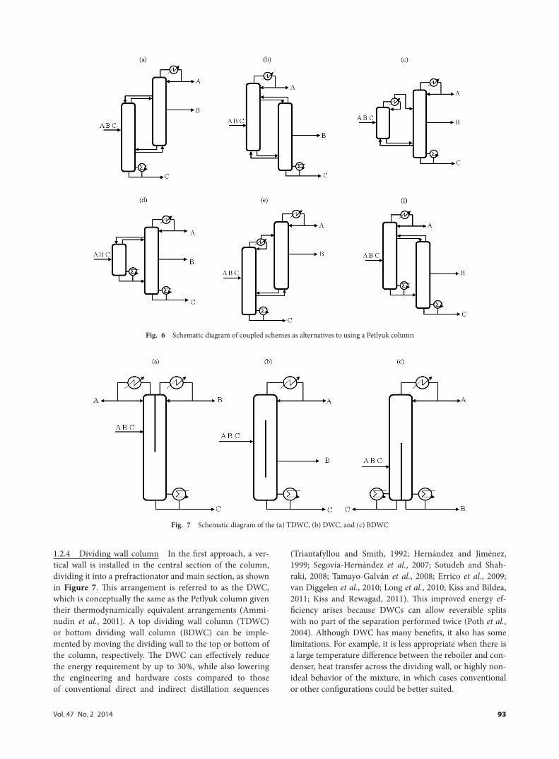
1.2.4 Dividing wall column In the first approach, a ver-tical wall is installed in the central section of the column, dividing it into a prefractionator and main section, as shown in Figure 7. This arrangement is referred to as the DWC, which is conceptually the same as the Petlyuk column given their thermodynamically equivalent arrangements (Ammi-nudin et al., 2001). A top dividing wall column (TDWC) or bottom dividing wall column (BDWC) can be imple-mented by moving the dividing wall to the top or bottom of the column, respectively. The DWC can effectively reduce the energy requirement by up to 30%, while also lowering the engineering and hardware costs compared to those of conventional direct and indirect distillation sequences
(Triantafyllou and Smith, 1992; Hernández and Jiménez, 1999; Segovia-Hernández et al., 2007; Sotudeh and Shah-raki, 2008; Tamayo-Galván et al., 2008; Errico et al., 2009; van Diggelen et al., 2010; Long et al., 2010; Kiss and Bildea, 2011; Kiss and Rewagad, 2011). This improved energy ef-ficiency arises because DWCs can allow reversible splits with no part of the separation performed twice (Poth et al., 2004). Although DWC has many benefits, it also has some limitations. For example, it is less appropriate when there is a large temperature difference between the reboiler and con-denser, heat transfer across the dividing wall, or highly non-ideal behavior of the mixture, in which cases conventional or other configurations could be better suited.
Fig. 6 Schematic diagram of coupled schemes as alternatives to using a Petlyuk column
Fig. 7 Schematic diagram of the (a) TDWC, (b) DWC, and (c) BDWC
94 Journal of Chemical Engineering of Japan
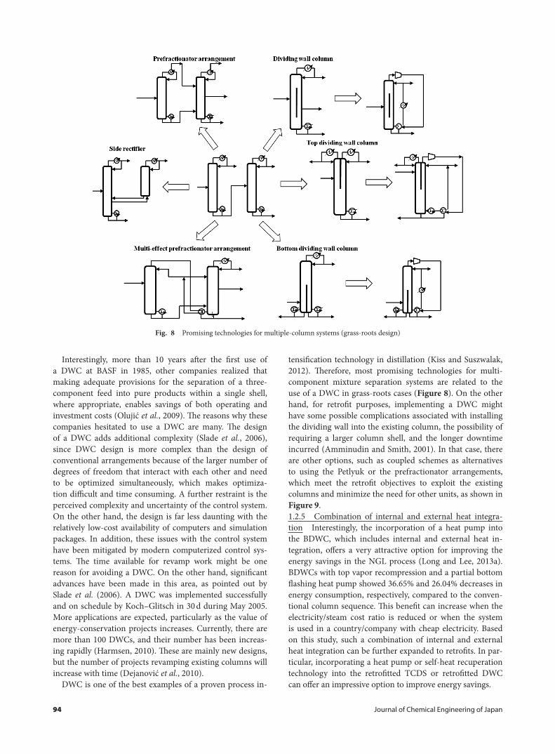
Interestingly, more than 10 years after the first use of a DWC at BASF in 1985, other companies realized that making adequate provisions for the separation of a three-component feed into pure products within a single shell, where appropriate, enables savings of both operating and investment costs (Olujić et al., 2009). The reasons why these companies hesitated to use a DWC are many. The design of a DWC adds additional complexity (Slade et al., 2006), since DWC design is more complex than the design of conventional arrangements because of the larger number of degrees of freedom that interact with each other and need to be optimized simultaneously, which makes optimiza-tion difficult and time consuming. A further restraint is the perceived complexity and uncertainty of the control system. On the other hand, the design is far less daunting with the relatively low-cost availability of computers and simulation packages. In addition, these issues with the control system have been mitigated by modern computerized control sys-tems. The time available for revamp work might be one reason for avoiding a DWC. On the other hand, significant advances have been made in this area, as pointed out by Slade et al. (2006). A DWC was implemented successfully and on schedule by Koch–Glitsch in 30 d during May 2005. More applications are expected, particularly as the value of energy-conservation projects increases. Currently, there are more than 100 DWCs, and their number has been increas-ing rapidly (Harmsen, 2010). These are mainly new designs, but the number of projects revamping existing columns will increase with time (Dejanović et al., 2010).
DWC is one of the best examples of a proven process in-
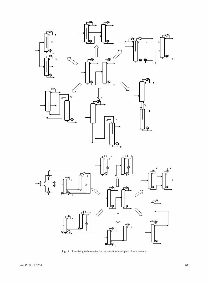
tensification technology in distillation (Kiss and Suszwalak, 2012). Therefore, most promising technologies for multi-component mixture separation systems are related to the use of a DWC in grass-roots cases (Figure 8). On the other hand, for retrofit purposes, implementing a DWC might have some possible complications associated with installing the dividing wall into the existing column, the possibility of requiring a larger column shell, and the longer downtime incurred (Amminudin and Smith, 2001). In that case, there are other options, such as coupled schemes as alternatives to using the Petlyuk or the prefractionator arrangements, which meet the retrofit objectives to exploit the existing columns and minimize the need for other units, as shown in Figure 9.1.2.5 Combination of internal and external heat integra-tion Interestingly, the incorporation of a heat pump into the BDWC, which includes internal and external heat in-tegration, offers a very attractive option for improving the energy savings in the NGL process (Long and Lee, 2013a). BDWCs with top vapor recompression and a partial bottom flashing heat pump showed 36.65% and 26.04% decreases in energy consumption, respectively, compared to the conven-tional column sequence. This benefit can increase when the electricity/steam cost ratio is reduced or when the system is used in a country/company with cheap electricity. Based on this study, such a combination of internal and external heat integration can be further expanded to retrofits. In par-ticular, incorporating a heat pump or self-heat recuperation technology into the retrofitted TCDS or retrofitted DWC can offer an impressive option to improve energy savings.
Fig. 8 Promising technologies for multiple-column systems (grass-roots design)
Vol. 47 No. 2 2014 95
Fig. 9 Promising technologies for the retrofit of multiple-column systems
96 Journal of Chemical Engineering of Japan
1.3 Azeotropic mixture1.3.1 Pressure-swing azeotropic distillation Azeotropic and close-boiling components are commonly encountered in fine-chemical and specialty industries. Minimum-boil-ing azeotropes appear when there is molecular repulsion between different types of chemical components, which is more common than molecular attractions, which re-sult in maximum-boiling azeotropes (Luyben, 2008a). The separation of these mixtures is a challenging task in many chemical processes and is impossible using a single con-ventional distillation column. Many non-conventional distillation techniques have been proposed to solve this problem (Widagdo and Seider, 1996; Doherty and Malone, 2001; Hamad and Dunn, 2002; Guedes et al., 2007; Gutiér-rez-Guerra et al., 2009). The most common alternatives involve changing the operating pressure or adding a separa-tion solvent.
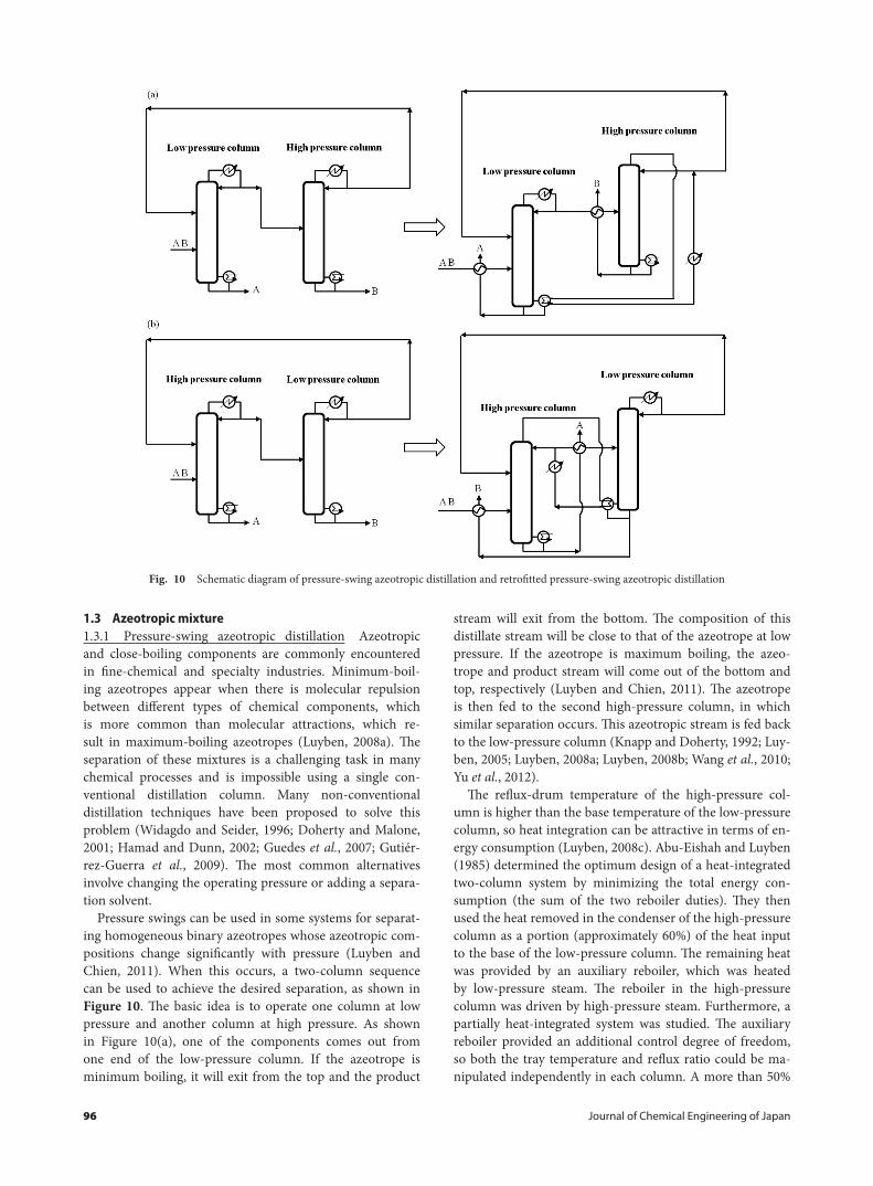
Pressure swings can be used in some systems for separat-ing homogeneous binary azeotropes whose azeotropic com-positions change significantly with pressure (Luyben and Chien, 2011). When this occurs, a two-column sequence can be used to achieve the desired separation, as shown in Figure 10. The basic idea is to operate one column at low pressure and another column at high pressure. As shown in Figure 10(a), one of the components comes out from one end of the low-pressure column. If the azeotrope is minimum boiling, it will exit from the top and the product
stream will exit from the bottom. The composition of this distillate stream will be close to that of the azeotrope at low pressure. If the azeotrope is maximum boiling, the azeo-trope and product stream will come out of the bottom and top, respectively (Luyben and Chien, 2011). The azeotrope is then fed to the second high-pressure column, in which similar separation occurs. This azeotropic stream is fed back to the low-pressure column (Knapp and Doherty, 1992; Luy-ben, 2005; Luyben, 2008a; Luyben, 2008b; Wang et al., 2010; Yu et al., 2012).
The reflux-drum temperature of the high-pressure col-umn is higher than the base temperature of the low-pressure column, so heat integration can be attractive in terms of en-ergy consumption (Luyben, 2008c). Abu-Eishah and Luyben (1985) determined the optimum design of a heat-integrated two-column system by minimizing the total energy con-sumption (the sum of the two reboiler duties). They then used the heat removed in the condenser of the high-pressure column as a portion (approximately 60%) of the heat input to the base of the low-pressure column. The remaining heat was provided by an auxiliary reboiler, which was heated by low-pressure steam. The reboiler in the high-pressure column was driven by high-pressure steam. Furthermore, a partially heat-integrated system was studied. The auxiliary reboiler provided an additional control degree of freedom, so both the tray temperature and reflux ratio could be ma-nipulated independently in each column. A more than 50%
Fig. 10 Schematic diagram of pressure-swing azeotropic distillation and retrofitted pressure-swing azeotropic distillation
Vol. 47 No. 2 2014 97
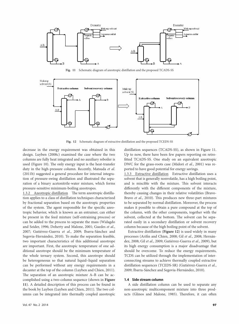
decrease in the energy requirement was obtained in this design. Luyben (2008c) examined the case where the two columns are fully heat integrated and no auxiliary reboiler is used (Figure 10). The only energy input is the heat-transfer duty in the high-pressure column. Recently, Matsuda et al. (2011b) suggested a general procedure for internal integra-tion of pressure-swing distillation and illustrated the sepa-ration of a binary acetonitrile-water mixture, which forms pressure-sensitive minimum-boiling azeotropes.1.3.2 Azeotropic distillation The term azeotropic distilla-tion applies to a class of distillation techniques characterized by fractional separation based on the azeotropic properties of the system. The agent responsible for the specific azeo-tropic behavior, which is known as an entrainer, can either be present in the feed mixture (self-entraining process) or can be added to the process to separate the mass (Widagdo and Seider, 1996; Doherty and Malone, 2001; Guedes et al., 2007; Gutiérrez-Guerra et al., 2009; Ibarra-Sánchez and Segovia-Hernández, 2010). To make the separation feasible, two important characteristics of this additional azeotrope are important. First, the azeotropic temperature of one ad-ditional azeotrope should be the minimum temperature of the whole ternary system. Second, this azeotrope should be heterogeneous so that natural liquid–liquid separation can be performed without any energy requirements in a decanter at the top of the column (Luyben and Chien, 2011). The separation of an azeotropic mixture A–B can be ac-complished using a two-column sequence (shown in Figure 11). A detailed description of this process can be found in the book by Luyben (Luyben and Chien, 2011). The two col-umns can be integrated into thermally coupled azeotropic
distillation sequences (TCADS-SS), as shown in Figure 11. Up to now, there have been few papers reporting on retro-fitted TCADS-SS. One study on an equivalent azeotropic DWC for the grass-roots case (Midori et al., 2001) was re-ported to have good potential for energy savings.1.3.3 Extractive distillation Extractive distillation uses a solvent that is generally nonvolatile, has a high boiling point, and is miscible with the mixture. This solvent interacts differently with the different components of the mixture, thereby causing changes in their relative volatilities (Bravo-Bravo et al., 2010). This produces new three-part mixtures to be separated by normal distillation. Moreover, the process makes it possible to obtain a pure compound at the top of the column, with the other components, together with the solvent, collected at the bottom. The solvent can be sepa-rated easily in a secondary distillation or solvent recovery column because of the high boiling point of the solvent.
Extractive distillation (Figure 12) is used widely in many processes (Arifin and Chien, 2008; Gil et al., 2008; Hernán-dez, 2008; Gil et al., 2009; Gutiérrez-Guerra et al., 2009), but its high energy consumption is a major disadvantage that should be overcome. To reduce the energy requirements, TCDS can be utilized through the implementation of inter-connecting streams to achieve thermally coupled extractive distillation sequences (TCEDS-SR) (Gutiérrez-Guerra et al., 2009; Ibarra-Sánchez and Segovia-Hernández, 2010).
1.4 Side stream columnA side distillation column can be used to separate any
non-azeotropic multicomponent mixture into three prod-ucts (Glinos and Malone, 1985). Therefore, it can often
Fig. 11 Schematic diagram of azeotropic distillation and the proposed TCADS-SS
Fig. 12 Schematic diagram of extractive distillation and the proposed TCEDS-SS
98 Journal of Chemical Engineering of Japan
replace a sequence of two columns. On the other hand, the purity of the side distillation product is restricted by ther-modynamics and by the nature of the distillation process. These columns are normally appropriate either as prefrac-tionators (the side stream is fed to another column for further separation) or to generate recycle streams when there are no strict requirements on the recycle composition. They are also used widely in the petroleum industry, where blends are produced rather than pure products.
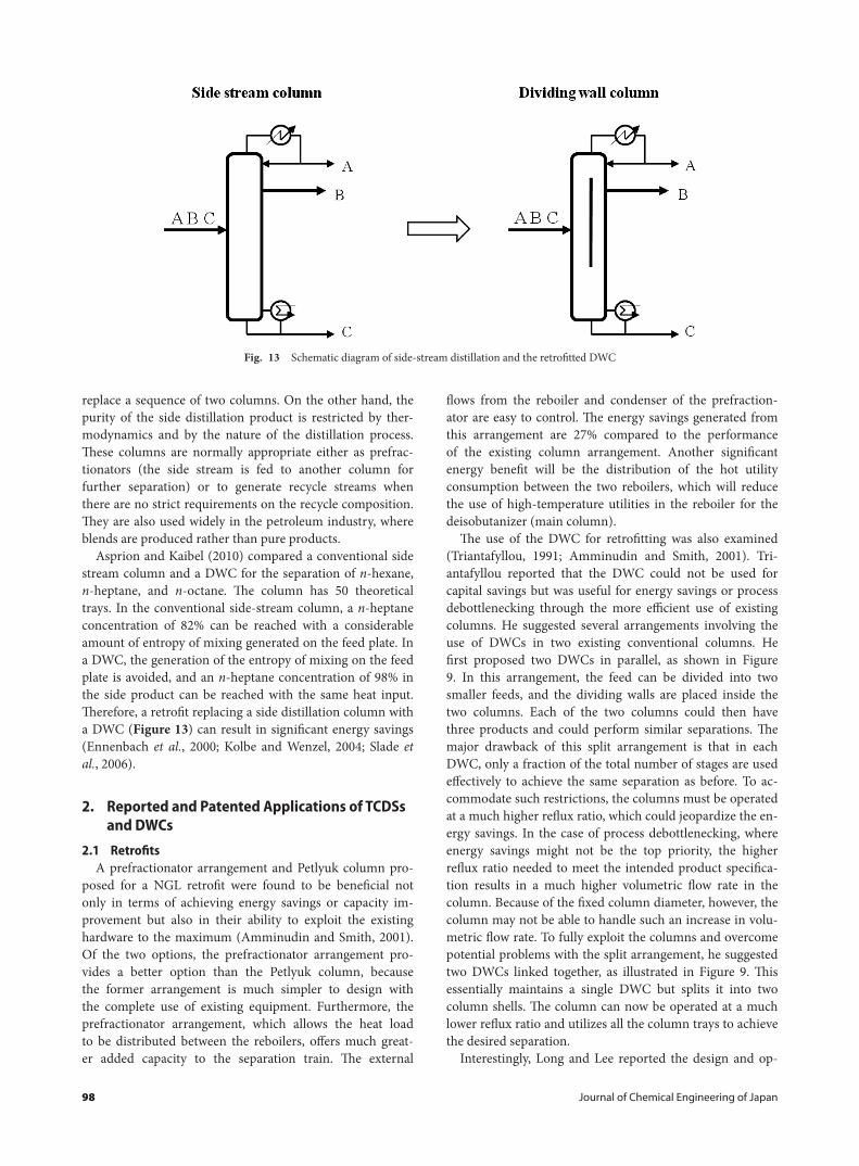
Asprion and Kaibel (2010) compared a conventional side stream column and a DWC for the separation of n-hexane, n-heptane, and n-octane. The column has 50 theoretical trays. In the conventional side-stream column, a n-heptane concentration of 82% can be reached with a considerable amount of entropy of mixing generated on the feed plate. In a DWC, the generation of the entropy of mixing on the feed plate is avoided, and an n-heptane concentration of 98% in the side product can be reached with the same heat input. Therefore, a retrofit replacing a side distillation column with a DWC (Figure 13) can result in significant energy savings (Ennenbach et al., 2000; Kolbe and Wenzel, 2004; Slade et al., 2006).
2. Reported and Patented Applications of TCDSs and DWCs
2.1 Retro�tsA prefractionator arrangement and Petlyuk column pro-
posed for a NGL retrofit were found to be beneficial not only in terms of achieving energy savings or capacity im-provement but also in their ability to exploit the existing hardware to the maximum (Amminudin and Smith, 2001). Of the two options, the prefractionator arrangement pro-vides a better option than the Petlyuk column, because the former arrangement is much simpler to design with the complete use of existing equipment. Furthermore, the prefractionator arrangement, which allows the heat load to be distributed between the reboilers, offers much great-er added capacity to the separation train. The external
flows from the reboiler and condenser of the prefraction-ator are easy to control. The energy savings generated from this arrangement are 27% compared to the performance of the existing column arrangement. Another significant energy benefit will be the distribution of the hot utility consumption between the two reboilers, which will reduce the use of high-temperature utilities in the reboiler for the deisobutanizer (main column).
The use of the DWC for retrofitting was also examined (Triantafyllou, 1991; Amminudin and Smith, 2001). Tri-antafyllou reported that the DWC could not be used for capital savings but was useful for energy savings or process debottlenecking through the more efficient use of existing columns. He suggested several arrangements involving the use of DWCs in two existing conventional columns. He first proposed two DWCs in parallel, as shown in Figure 9. In this arrangement, the feed can be divided into two smaller feeds, and the dividing walls are placed inside the two columns. Each of the two columns could then have three products and could perform similar separations. The major drawback of this split arrangement is that in each DWC, only a fraction of the total number of stages are used effectively to achieve the same separation as before. To ac-commodate such restrictions, the columns must be operated at a much higher reflux ratio, which could jeopardize the en-ergy savings. In the case of process debottlenecking, where energy savings might not be the top priority, the higher reflux ratio needed to meet the intended product specifica-tion results in a much higher volumetric flow rate in the column. Because of the fixed column diameter, however, the column may not be able to handle such an increase in volu-metric flow rate. To fully exploit the columns and overcome potential problems with the split arrangement, he suggested two DWCs linked together, as illustrated in Figure 9. This essentially maintains a single DWC but splits it into two column shells. The column can now be operated at a much lower reflux ratio and utilizes all the column trays to achieve the desired separation.
Interestingly, Long and Lee reported the design and op-
Fig. 13 Schematic diagram of side-stream distillation and the retrofitted DWC
Vol. 47 No. 2 2014 99
timization for a retrofit in which an extractive distillation sequence was converted to a thermally coupled extractive distillation sequence using a side rectifier (Long and Lee, 2013b). This process could be adapted easily to include the hydraulic capacity and the total number of stages of the ex-isting columns involved in the retrofit. Retrofitting of an ex-tractive distillation sequence can achieve significant energy savings with few modifications. Furthermore, retrofitting to a TCEDS-SR can not only utilize existing columns, but can also increase the process capacity. In several cases, how-ever, this can create a bottleneck in the column. Long and Lee (2013d) utilized fractional utilization of area (FUA) to identify bottlenecks in a retrofitted TCDS systematically and proposed a novel strategy for the use of a side reboiler or a side condenser for debottlenecking the column. The use of a side reboiler or a side condenser in a retrofitted TCDS could debottleneck the column and increase the process capacity. This can reduce the temperature difference between the top and side reboiler location, or between the bottom and side condenser location, which allows potential use of a heat pump by utilizing the heat from the top vapor stream or side vapor stream, respectively. The column grand composite curve (CGCC) was used to indicate the thermodynamic fea-sibility of the implementation of the heat pump system into the TCDS.
ExxonMobil successfully refurbished a conventional tray xylenes distillation column (Slade et al., 2006). This column takes a xylene side stream from the reformate to feed an aromatics plant to produce higher value products. The entire project cycle is detailed in this report, including the process design, hydraulic design, mechanical design, manufacture, testing, and site work. Changing the column configuration to a DWC resulted in energy savings of up to 53% along with improvements in the xylenes’ purity. The column con-denser and reboiler did not require any modifications. The product cooler was also reused without modification, even though it was rather oversized. The design required several new nozzles to be installed for the bypass, feed, and product draw-off, plus new instrumentation.
Kolbe and Wenzel (2004) presented some industrial ex-amples of the implementation of a DWC by Uhde. One of them is the revamp of a side distillation column for process-ing pyrolysis gasoline at Ruhr Oel. The project was driven mainly by the modified European specifications for gasoline, which limit the benzene content in mixed gasoline (over-head product plus bottom product) to a maximum of 1% by volume. By removing the middle section of the column shell equipped with the trays and inserting a divided-wall segment equipped with structured packing, this project in-creased the benzene yield and concentration in the side-draw and the column capacity. Interestingly, the modifi-cation was planned in such a way to allow the complete reconstruction from the “ready for opening” to the “ready for feed-in” stage in a plant shutdown period of only 10 d. In this narrow time period, the existing column shell was cut into three pieces. A part of the adjacent piping was also demolished. The prefabricated new column section was then
partly wedded with the new piping attached. The internals for the new section were installed and leveled on-site. Some of the pump sets were also replaced to match the new de-bottlenecking capacity.
A DWC developed by our team (PSDC) along with the LG CRD team was implemented successfully and started up in the LG Naju plant in 2008. This commercial DWC was designed by the DWC project team only with domestic tech-nology. Start-up of the commercial DWC was completed successfully. Changing the column configuration to a DWC resulted in improved product purity and significant energy savings (up to 40%). This DWC is considered the first com-mercial DWC in Korea.
Six applications of industrial importance were selected, and conventional two-column systems were designed, which were assumed to be currently in operation in the plants (Premkumar and Rangaiah, 2009). The retrofitting of these systems to implement DWCs was then studied. The results showed that retrofitting the existing two-column systems with DWCs is quite attractive, both economically and for the reduced energy requirements.
Recently, Long and Lee (2013e) reported the potential for retrofitting a side distillation column as a DWC. The mini-mum energy requirement for the separation of a multicom-ponent mixture was used in this feasibility study, whereas the response surface methodology was used to minimize the reboiler duty. These results showed that the DWC can save up to 25.16% in energy. Furthermore, the maximum flooding was reduced from 87% to 80%, which has the po-tential to increase the plant production capacity.
2.2 DebottleneckingFor an existing distillation process with a fixed feed com-
position, there will be a maximum feed flow rate for the separation below which certain fixed product specifications can be met (Liu and Jobson, 2004a). The bottleneck of the process is that a particular piece of the installed equipment cannot accommodate flow rates higher than those associat-ed with this maximum feed flow rate. Above the maximum feed flow rate, the column producing the main product might no longer be able to perform as required, or the downcomers in the column may flood, etc. The goal of such a retrofit design is to identify and remove such bottlenecks.
DWC can be used to remove the bottleneck phenomenon as well as improve the energy efficiency when increasing the throughput. One of main ideas is to shift the increased load to the subsequent columns and have the DWC take care of the load (Long et al., 2010). A range of possible distillation arrangements were studied, along with the DWC configuration. The results suggest that the DWC can oper-ate as an efficient replacement for a conventional column in a retrofit for the debottlenecking of distillation processes, while requiring less investment and energy costs than con-ventional distillation, Petlyuk column, and prefractionator arrangements.
The key to a successful retrofit lies in maximizing the utilization of the existing equipment while simultaneously
100 Journal of Chemical Engineering of Japan
minimizing the new hardware to reduce the capital costs. Nevertheless, these modifications require plant downtime. In many retrofit projects, downtime is the largest economic factor, because it leads to a loss of production and an inter-ruption of the product supply to customers (Amminudin and Smith, 2001). On the other hand, each retrofit should be considered based on the specific conditions of each particu-lar case, such as the component characteristics, operating conditions, number of trays, equipment lifetime, construc-tion material, and feed composition. Long and Lee (2011) proposed some rules for achieving a successful retrofit.
3. Discussion
3.1 ConstraintsIn general, a retrofit project for a distillation process
covers a wide range of modifications and utilizes existing processes ranging from a simple modification or replace-ment of column internals only, to large modifications of the column configuration, partial enlargement of the shell di-ameter and height, and modification of auxiliary equipment. In any case, the key to a successful retrofit lies in exploiting the existing hardware by maximizing the use of existing equipment while, at the same time, minimizing the need for new hardware to minimize the capital cost. To mini-mize the modifications in a retrofit, the number of trays of all columns and their diameter should be fixed to the same number in conventional distillation columns.
To integrate two columns into a single DWC, the operat-ing pressure of the retrofitted DWC is normally adjusted to that of the column with the high pressure in order to condense the top product with the same cooling utility. This causes an increase in temperature in the bottom of the column. Sometimes, it is important to change the steam pressure level, such as from low-pressure steam to medium-pressure steam or from medium-pressure steam to high-pressure steam, which causes an increase in the operating cost. This can be a significant problem for some chemical plants whose products are sensitive to temperature. Polym-erization and other reactions can occur when the column temperature increases, which causes fouling problems or produces unwanted products. In this case, the operating pressure of the DWC needs to be reduced to provide a lower operating temperature.
The top section of the two columns should also be consid-ered, because many companies try to utilize the heat from the top vapor stream to produce steam. If this occurs, the attempt to reduce the energy requirement at the bottom will be unsuccessful. Note that the price of high-pressure steam is almost 1.1 times higher than that of medium-pressure steam, whose cost is also 1.1 times higher than that of low-pressure steam.
In principle, DWCs can be used as both tray and packed columns (Yildirim et al., 2011). On the other hand, up to now, the majority have been constructed by Montz (2013) and used as packed columns by BASF SE. In some sequences that encounter fouling problems, the tray type is preferred,
whereas vacuum applications are dominated by structured packing. The integration of two columns, where one column has a fouling problem and another has structured packing, into DWCs can be a difficult problem. A packing type that is unsuitable for fouling problems should not be used, and the tray type, which has high pressure drop, will also be unsat-isfactory when the column is operated at vacuum pressure.
Another problem is related to corrosion phenomena. In the production of a chemical plant, the construction mate-rial needs to be considered carefully because of corrosion. In the separation sequence, some columns have good cor-rosion resistance, whereas others do not. The addition of a new column, such as a post-fractionator or prefractionator, can also provide a process debottlenecking option (Lieb-man, 1991). Accordingly, the construction material for the new column, which is related directly to the investment cost and corrosion phenomenon, must also be considered. While some modification methods have been proposed to reduce the investment and operating costs, it is necessary to con-sider each particular case based on realistic conditions.
In the case of a retrofit to implement a side rectifier, a vapor stream is needed to thermally couple the two col-umns. Gas is normally transported when a compressor applies a pressure difference between the inlet and outlet, which results in more investment and operating cost. The pressure at the vapor stream tray location is normally de-signed to be higher than that in the bottom section of the side rectifier. Therefore, a compressor is not needed in this retrofit design. In some special cases, such as when it is necessary to prevent a reaction or product decomposition, the main column must be operated at a lower pressure than that in the bottom section of the side rectifier, which would require a compressor. Engineers should be aware of the ad-ditional investment and operating cost to determine if the project will continue.
A heat pump can also be used in a retrofit design, be-cause they are easy to introduce and the plant operation is normally simpler than when heat integration is used. On the other hand, the high capital expenditure required for compressors make them industrially viable only for high-capacity, end-of-train (practically binary) separations of substances with similar boiling points, which require minimal compressor/compression costs. This is the case mainly in the separation of light hydrocarbons such as the C2, C3, and C4 components, where the adiabatic exponents of the substances are large enough to enable significant temperature increases with relatively low compression ef-fort (Stichlmair, 1988; Dejanović et al., 2010; Matsuda et al., 2011a). Furthermore, in a heat pump, usually only the heat recovery duty of the reboiler in the distillation column is considered, while the heat introduced during preheating is not, or is at least less recognized (Matsuda et al., 2011a). When a heat pump is used, engineers should consider the reactions that can take place as the vapor pressure and temperature are increased. In some cases where this is a problem, a heat pump cannot be used even if the energy re-quirements can be reduced.
Vol. 47 No. 2 2014 101
3.2 TechnicalWhen two columns are retrofit to form a DWC, the
selected, existing column is modified by the addition of a middle section that houses the dividing wall (Premkumar and Rangaiah, 2009). This column will be cut on-site into two portions to form the top and bottom sections of the retrofitted DWC. The middle section of the retrofitted DWC is shop-fabricated and would be available before the actual on-site retrofitting begins. This section is first welded to the top of the bottom section, and the removed top portion will then be welded on top of the middle section to complete the column. In this exercise, the number of stages in the existing column would be sufficient to meet the required number of stages in the top and bottom sections of the DWC. Essen-tially, the existing column is fully utilized, limiting the col-umn modification to the addition of a middle section only. In contrast, the retrofit of a side column to implement a DWC includes removing the existing trays and adding new trays (if necessary) and a new dividing wall into the middle section. Another approach is to cut the existing column shell into three pieces (Kolbe and Wenzel, 2004), where the prefabricated new column section is then welded in. The in-ternals for the new section are installed and leveled on-site. In addition, some of the pump sets are replaced to match the new debottlenecking capacity. The design, engineering, and operation of the DWCs was found to be practicable without difficulties. From a technique point of view, the retrofit of a side stream column to implement a DWC can be preferable over retrofitting two columns to form a DWC.
These modifications incur significant plant downtime (Long and Lee, 2013b). In many retrofit projects, downtime is the largest economic factor, and a significant amount can lead to a loss of production and an interruption in product supply. In an integrated facility, where plants depend on each other, such downtime can disrupt other downstream processes. In project discussed in the paper by Long and Lee (2013b), the feed and aniline stream nozzles were moved from the 21st and 28th trays to the 20th and 29th trays, respectively, which required some modifications. Energy savings of up to 31.65% are still possible when the feed lo-cations remain in the conventional positions. Even though the optimum point provides better operating cost savings, keeping the same location of the feeds is preferred because fewer modifications are required. The operating cost and in-vestment are a trade-off to be considered in a retrofit design (Long et al., 2010).
3.3 Economic analysisEstimating the capital cost of a retrofit project is much
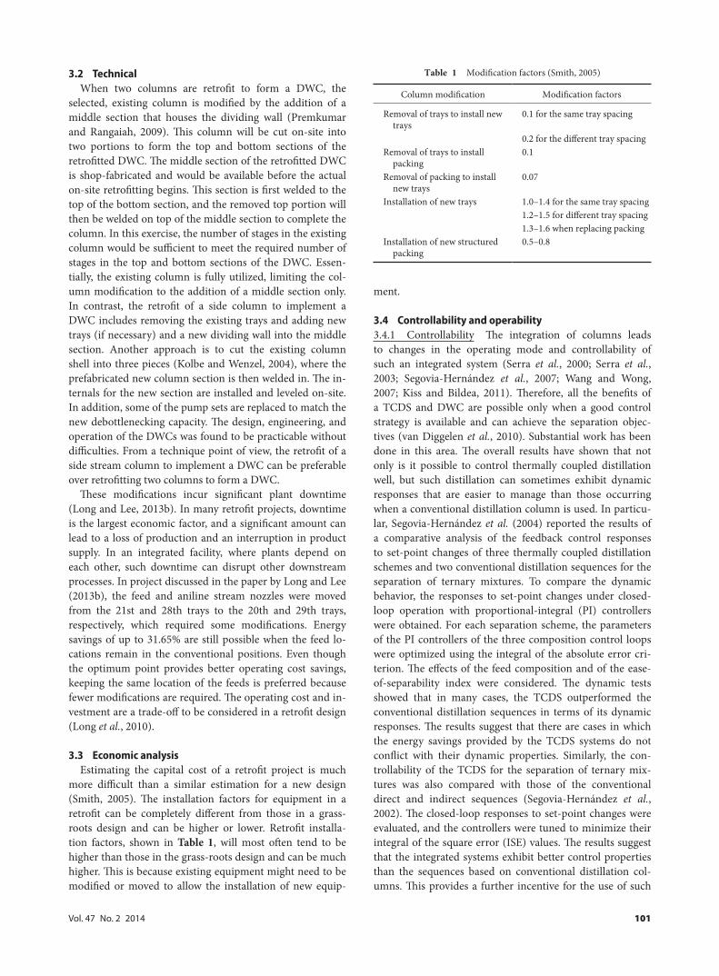
more difficult than a similar estimation for a new design (Smith, 2005). The installation factors for equipment in a retrofit can be completely different from those in a grass-roots design and can be higher or lower. Retrofit installa-tion factors, shown in Table 1, will most often tend to be higher than those in the grass-roots design and can be much higher. This is because existing equipment might need to be modified or moved to allow the installation of new equip-
ment.
3.4 Controllability and operability3.4.1 Controllability The integration of columns leads to changes in the operating mode and controllability of such an integrated system (Serra et al., 2000; Serra et al., 2003; Segovia-Hernández et al., 2007; Wang and Wong, 2007; Kiss and Bildea, 2011). Therefore, all the benefits of a TCDS and DWC are possible only when a good control strategy is available and can achieve the separation objec-tives (van Diggelen et al., 2010). Substantial work has been done in this area. The overall results have shown that not only is it possible to control thermally coupled distillation well, but such distillation can sometimes exhibit dynamic responses that are easier to manage than those occurring when a conventional distillation column is used. In particu-lar, Segovia-Hernández et al. (2004) reported the results of a comparative analysis of the feedback control responses to set-point changes of three thermally coupled distillation schemes and two conventional distillation sequences for the separation of ternary mixtures. To compare the dynamic behavior, the responses to set-point changes under closed-loop operation with proportional-integral (PI) controllers were obtained. For each separation scheme, the parameters of the PI controllers of the three composition control loops were optimized using the integral of the absolute error cri-terion. The effects of the feed composition and of the ease-of-separability index were considered. The dynamic tests showed that in many cases, the TCDS outperformed the conventional distillation sequences in terms of its dynamic responses. The results suggest that there are cases in which the energy savings provided by the TCDS systems do not conflict with their dynamic properties. Similarly, the con-trollability of the TCDS for the separation of ternary mix-tures was also compared with those of the conventional direct and indirect sequences (Segovia-Hernández et al., 2002). The closed-loop responses to set-point changes were evaluated, and the controllers were tuned to minimize their integral of the square error (ISE) values. The results suggest that the integrated systems exhibit better control properties than the sequences based on conventional distillation col-umns. This provides a further incentive for the use of such
Table 1 Modification factors (Smith, 2005)
Column modification Modification factors
Removal of trays to install new trays
0.1 for the same tray spacing
0.2 for the different tray spacingRemoval of trays to install
packing0.1
Removal of packing to install new trays
0.07
Installation of new trays 1.0–1.4 for the same tray spacing1.2–1.5 for different tray spacing1.3–1.6 when replacing packing
Installation of new structured packing
0.5–0.8
102 Journal of Chemical Engineering of Japan
integrated systems.One study reported the production of ethyl acetate from
ethanol and acetic acid using three reactive thermally coupled systems (Barroso-Muñoz et al., 2007). Dynamic closed-loop responses were obtained for the most energy-efficient reactive distillation scheme (Petlyuk column). The results showed that with this complex scheme, one can achieve changes in the set point and also eliminate the ef-fect of disturbances using only simple PI controllers tuned using Ziegler and Nichols’s method. From these results, they concluded that TCDS has significant advantages over the classical process used to produce ethyl acetate.
Mutalib and Smith (1998) analyzed two control configu-rations (L-S-V and D-S-V) for the Petlyuk column and re-ported that both schemes achieve satisfactory control, with the D-S-V structure providing better dynamic performance. Furthermore, Mutalib et al. (1998) reported the results from both dynamic simulations and the experimental tests for the Petlyuk column. Through temperature control, they were able to obtain stable performance of the column under feed condition disturbances.
A profile position control scheme was proposed to over-come the control problems (Cho et al., 2009). Relative gain array analysis and singular value decomposition were used to determine the optimal control configuration. A dynamic simulation showed that the profile position–product com-position cascade control can maintain the product purity at the desired values despite feed disturbances and internal disturbances. Kiss and Rewagad (2011) compared sever-al conventional control structures based on proportional-integral-derivative (PID) control loops enhanced using the liquid split as an additional manipulated variable, thereby implicitly achieving minimal energy requirements. They reported dynamic results showing good DWC controllabil-ity, relatively short settling times, and low overshoot.
Recently, two-point temperature control structures for DWCs were investigated to overcome the difficulties aris-ing from their complicated natures (Kim et al., 2012). The control performance for the DWCs was assessed under nine different feed conditions characterized by the composition of an intermediate component and the relative volatilities. Steady-state and dynamic simulations were performed to analyze the closed-loop responses for various two-point
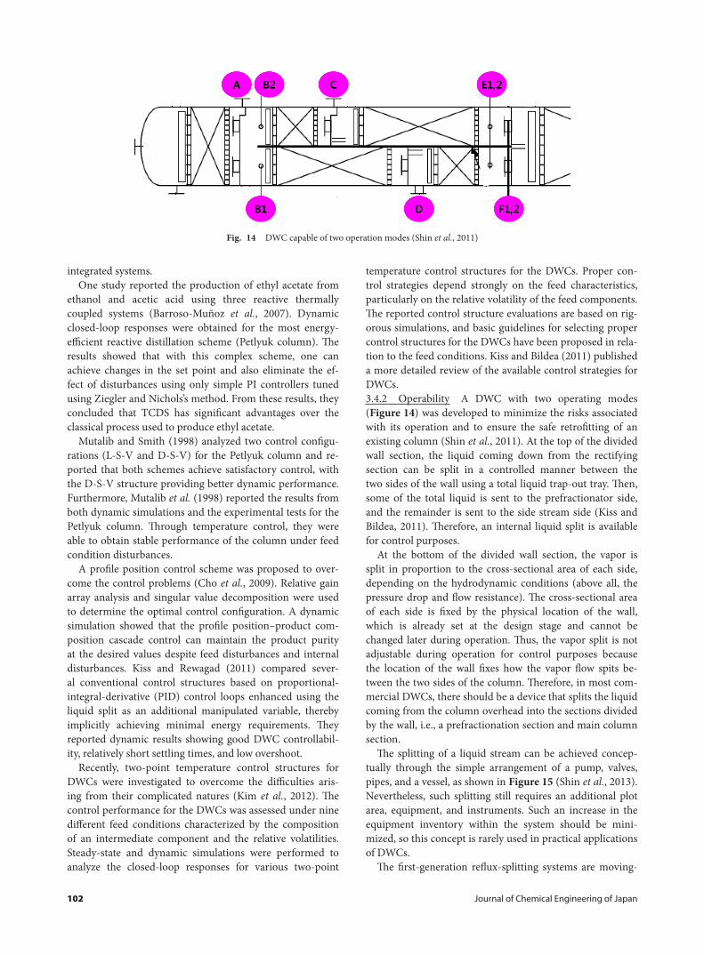
temperature control structures for the DWCs. Proper con-trol strategies depend strongly on the feed characteristics, particularly on the relative volatility of the feed components. The reported control structure evaluations are based on rig-orous simulations, and basic guidelines for selecting proper control structures for the DWCs have been proposed in rela-tion to the feed conditions. Kiss and Bildea (2011) published a more detailed review of the available control strategies for DWCs.3.4.2 Operability A DWC with two operating modes (Figure 14) was developed to minimize the risks associated with its operation and to ensure the safe retrofitting of an existing column (Shin et al., 2011). At the top of the divided wall section, the liquid coming down from the rectifying section can be split in a controlled manner between the two sides of the wall using a total liquid trap-out tray. Then, some of the total liquid is sent to the prefractionator side, and the remainder is sent to the side stream side (Kiss and Bildea, 2011). Therefore, an internal liquid split is available for control purposes.
At the bottom of the divided wall section, the vapor is split in proportion to the cross-sectional area of each side, depending on the hydrodynamic conditions (above all, the pressure drop and flow resistance). The cross-sectional area of each side is fixed by the physical location of the wall, which is already set at the design stage and cannot be changed later during operation. Thus, the vapor split is not adjustable during operation for control purposes because the location of the wall fixes how the vapor flow spits be-tween the two sides of the column. Therefore, in most com-mercial DWCs, there should be a device that splits the liquid coming from the column overhead into the sections divided by the wall, i.e., a prefractionation section and main column section.
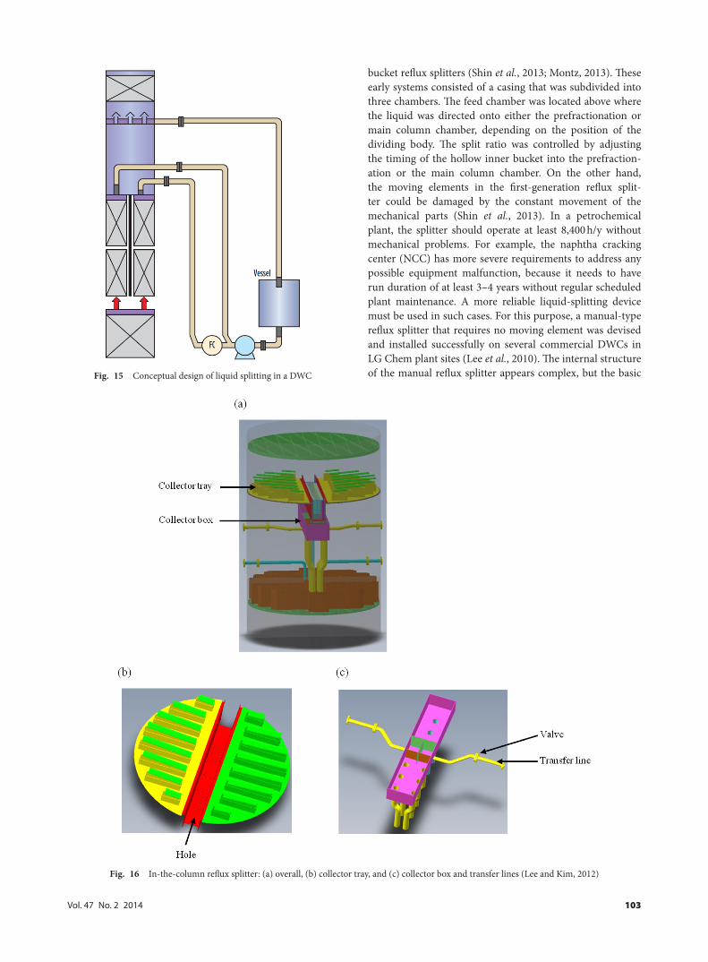
The splitting of a liquid stream can be achieved concep-tually through the simple arrangement of a pump, valves, pipes, and a vessel, as shown in Figure 15 (Shin et al., 2013). Nevertheless, such splitting still requires an additional plot area, equipment, and instruments. Such an increase in the equipment inventory within the system should be mini-mized, so this concept is rarely used in practical applications of DWCs.
The first-generation reflux-splitting systems are moving-
Fig. 14 DWC capable of two operation modes (Shin et al., 2011)
Vol. 47 No. 2 2014 103
bucket reflux splitters (Shin et al., 2013; Montz, 2013). These early systems consisted of a casing that was subdivided into three chambers. The feed chamber was located above where the liquid was directed onto either the prefractionation or main column chamber, depending on the position of the dividing body. The split ratio was controlled by adjusting the timing of the hollow inner bucket into the prefraction-ation or the main column chamber. On the other hand, the moving elements in the first-generation reflux split-ter could be damaged by the constant movement of the mechanical parts (Shin et al., 2013). In a petrochemical plant, the splitter should operate at least 8,400 h/y without mechanical problems. For example, the naphtha cracking center (NCC) has more severe requirements to address any possible equipment malfunction, because it needs to have run duration of at least 3–4 years without regular scheduled plant maintenance. A more reliable liquid-splitting device must be used in such cases. For this purpose, a manual-type reflux splitter that requires no moving element was devised and installed successfully on several commercial DWCs in LG Chem plant sites (Lee et al., 2010). The internal structure of the manual reflux splitter appears complex, but the basic Fig. 15 Conceptual design of liquid splitting in a DWC
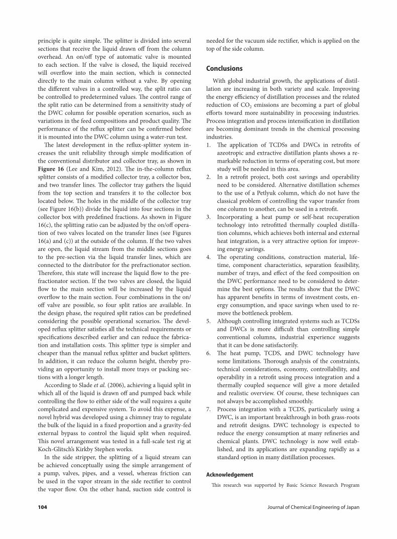
Fig. 16 In-the-column reflux splitter: (a) overall, (b) collector tray, and (c) collector box and transfer lines (Lee and Kim, 2012)
104 Journal of Chemical Engineering of Japan
principle is quite simple. The splitter is divided into several sections that receive the liquid drawn off from the column overhead. An on/off type of automatic valve is mounted to each section. If the valve is closed, the liquid received will overflow into the main section, which is connected directly to the main column without a valve. By opening the different valves in a controlled way, the split ratio can be controlled to predetermined values. The control range of the split ratio can be determined from a sensitivity study of the DWC column for possible operation scenarios, such as variations in the feed compositions and product quality. The performance of the reflux splitter can be confirmed before it is mounted into the DWC column using a water-run test.
The latest development in the reflux-splitter system in-creases the unit reliability through simple modification of the conventional distributor and collector tray, as shown in Figure 16 (Lee and Kim, 2012). The in-the-column reflux splitter consists of a modified collector tray, a collector box, and two transfer lines. The collector tray gathers the liquid from the top section and transfers it to the collector box located below. The holes in the middle of the collector tray (see Figure 16(b)) divide the liquid into four sections in the collector box with predefined fractions. As shown in Figure 16(c), the splitting ratio can be adjusted by the on/off opera-tion of two valves located on the transfer lines (see Figures 16(a) and (c)) at the outside of the column. If the two valves are open, the liquid stream from the middle sections goes to the pre-section via the liquid transfer lines, which are connected to the distributor for the prefractionator section. Therefore, this state will increase the liquid flow to the pre-fractionator section. If the two valves are closed, the liquid flow to the main section will be increased by the liquid overflow to the main section. Four combinations in the on/off valve are possible, so four split ratios are available. In the design phase, the required split ratios can be predefined considering the possible operational scenarios. The devel-oped reflux splitter satisfies all the technical requirements or specifications described earlier and can reduce the fabrica-tion and installation costs. This splitter type is simpler and cheaper than the manual reflux splitter and bucket splitters. In addition, it can reduce the column height, thereby pro-viding an opportunity to install more trays or packing sec-tions with a longer length.
According to Slade et al. (2006), achieving a liquid split in which all of the liquid is drawn off and pumped back while controlling the flow to either side of the wall requires a quite complicated and expensive system. To avoid this expense, a novel hybrid was developed using a chimney tray to regulate the bulk of the liquid in a fixed proportion and a gravity-fed external bypass to control the liquid split when required. This novel arrangement was tested in a full-scale test rig at Koch-Glitsch’s Kirkby Stephen works.
In the side stripper, the splitting of a liquid stream can be achieved conceptually using the simple arrangement of a pump, valves, pipes, and a vessel, whereas friction can be used in the vapor stream in the side rectifier to control the vapor flow. On the other hand, suction side control is
needed for the vacuum side rectifier, which is applied on the top of the side column.
Conclusions
With global industrial growth, the applications of distil-lation are increasing in both variety and scale. Improving the energy efficiency of distillation processes and the related reduction of CO2 emissions are becoming a part of global efforts toward more sustainability in processing industries. Process integration and process intensification in distillation are becoming dominant trends in the chemical processing industries.1. The application of TCDSs and DWCs in retrofits of
azeotropic and extractive distillation plants shows a re-markable reduction in terms of operating cost, but more study will be needed in this area.
2. In a retrofit project, both cost savings and operability need to be considered. Alternative distillation schemes to the use of a Petlyuk column, which do not have the classical problem of controlling the vapor transfer from one column to another, can be used in a retrofit.
3. Incorporating a heat pump or self-heat recuperation technology into retrofitted thermally coupled distilla-tion columns, which achieves both internal and external heat integration, is a very attractive option for improv-ing energy savings.
4. The operating conditions, construction material, life-time, component characteristics, separation feasibility, number of trays, and effect of the feed composition on the DWC performance need to be considered to deter-mine the best options. The results show that the DWC has apparent benefits in terms of investment costs, en-ergy consumption, and space savings when used to re-move the bottleneck problem.
5. Although controlling integrated systems such as TCDSs and DWCs is more difficult than controlling simple conventional columns, industrial experience suggests that it can be done satisfactorily.
6. The heat pump, TCDS, and DWC technology have some limitations. Thorough analysis of the constraints, technical considerations, economy, controllability, and operability in a retrofit using process integration and a thermally coupled sequence will give a more detailed and realistic overview. Of course, these techniques can not always be accomplished smoothly.
7. Process integration with a TCDS, particularly using a DWC, is an important breakthrough in both grass-roots and retrofit designs. DWC technology is expected to reduce the energy consumption at many refineries and chemical plants. DWC technology is now well estab-lished, and its applications are expanding rapidly as a standard option in many distillation processes.
Acknowledgement
This research was supported by Basic Science Research Program
Vol. 47 No. 2 2014 105
through the National Research Foundation of Korea (NRF) funded by the Ministry of Education, Science and Technology (2012012532).
Literature Cited
Abu-Eishah, S. I. and W. L. Luyben; “Design and Control of a Two-Column Azeotropic Distillation System,” Ind. Eng. Chem. Process Des. Dev., 24, 132–140 (1985)
Agrawal, R.; “More Operable Fully Thermally Coupled Distillation Col-umn Configurations for Multicomponent Distillation,” Chem. Eng. Res. Des., 77, 543–553 (1999)
Agrawal, R. and Z. Fidkowski; “More Operable Arrangements of Fully Thermally Coupled Distillation Columns,” AIChE J., 44, 2565–2568 (1998)
Agrawal, R. and Z. Fidkowski; “New Thermally Coupled Schemes for Ternary Distillation,” AIChE J., 45, 485–496 (1999)
Aguirre, P., J. Espinosa, E. Tarifa and N. Scenna; “Optimal Thermo-dynamic Approximation to Reversible Distillation by Means of Interheaters and Intercoolers,” Ind. Eng. Chem. Res., 36, 4882–4893 (1997)
Alatiqi, I. M. and W. L. Luyben; “Alternative Distillation Configura-tions for Separating Ternary Mixtures with Small Concentration of Intermediate in the Feed,” Ind. Eng. Chem. Process Des. Dev., 24, 500–506 (1985)
Amminudin, K. A. and R. Smith; “Design and Optimization of Fully Thermally Coupled Distillation Columns. Part 2: Application of Dividing Wall Columns in Retrofit,” Chem. Eng. Res. Des., 79, 716–724 (2001)
Amminudin, K. A., R. Smith, D. Y. C. Thong and G. P. Towler; “Design and Optimization of Fully Thermally Coupled Distillation Col-umns: Part 1: Preliminary Design and Optimization Methodol-ogy,” Chem. Eng. Res. Des., 79, 701–715 (2001)
Annakou, O. and P. Mizsey; “Rigorous Investigation of Heat Pump As-sisted Distillation,” Heat Recovery Syst. CHP, 15, 241–247 (1995)
Arifin, S. and I. L. Chien; “Design and Control of an Isopropyl Alcohol Dehydration Process via Extractive Distillation Using Dimethyl Sulfoxide as an Entrainer,” Ind. Eng. Chem. Res., 47, 790–803 (2008)
Asprion, N. and G. Kaibel; “Dividing Wall Columns: Fundamentals and Recent Advances,” Chem. Eng. Process., 49, 139–146 (2010)
Bandyopadhyay, S.; “Thermal Integration of a Distillation Column through Side-Exchangers,” Chem. Eng. Res. Des., 85, 155–166 (2007)
Barroso-Muñoz, F. O., S. Hernández and B. Ogunnaike; “Analysis of Design and Control of Reactive Thermally Coupled Distillation Sequences,” Comput.-Aided Chem. Eng., 24, 877–882 (2007)
Blancarte-Palacios, J. L., M. N. Bautista-Valadés, S. Hernández Castro, V. Rico-Ramírez and A. Jiménez; “Energy-Efficient Designs of Thermally Coupled Distillation Sequences for Four-Component Mixtures,” Ind. Eng. Chem. Res., 42, 5157–5164 (2003)
Bravo-Bravo, C., J. Segovia-Hernandez, C. Gutierrez-Antonio, A. Duran, A. Bonilla-Petriciolet and A. Briones-Ramirez; “Extrac-tive Dividing Wall Column: Design and Optimization,” Ind. Eng. Chem. Res., 49, 3672–3688 (2010)
Bruinsma, D. and S. Spoelstra; “Heat Pumps in Distillation,” Proc. Distillation and Absorption 2010, pp. 21–28, Eindhoven, the Neth-erland (2010)
Capps, R. W.; “Consider the Ultimate Capacity of Fractionation Trays,” Chem. Eng. Prog., 89, 37–42 (1993)
Castillo, F. J. L. and V. R. Dhole; “Pressure Analysis of the Ethylene Cold-End Process,” Comput. Chem. Eng., 19, 89–94 (1995)
Chen, Y. M. and C. Y. Sun; “Experimental Study of the Performance
Characteristics of a Steam-Ejector Refrigeration System,” Exp. �erm. Fluid Sci., 15, 384–394 (1997)
Cho, Y., B. Kim, D. Kim, M. Han and M. Lee; “Operation of Divided Wall Column with Vapor Sidedraw Using Profile Position Con-trol,” J. Process Contr., 19, 932–941 (2009)
Darakchiev, S. and K. Semkov; “A Study on Modern High-Effective Random Packings for Ethanol–Water Rectification,” Chem. Eng. Technol., 31, 1039–1045 (2008)
De Rijke, A.; Development of a Concentric Internally Heat Integrated Distillation Column, PhD Thesis, Technische Universiteit Deft, the Netherlands (2007)
Dejanović, I., Lj. Matijašević and Ž. Olujić; “Dividing Wall Column-A Breakthrough towards Sustainable Distilling,” Chem. Eng. Process., 49, 559–580 (2010)
Demirel, D. Y.; “Retrofit of Distillation Columns Using Thermodynamic Analysis,” Sep. Sci. Technol., 41, 791–817 (2006)
Deshmukh, B. F., R. K. Malik and S. Bandyopadhyay; “Efficient Feed Preheat Targeting for Distillation by Feed Splitting,” Comput. Aided Chem. Eng., 751–756 (2005)
Doherty, M. F. and M. F. Malone; Conceptual Design of Distillation Systems, Chemical Engineering Series. McGraw-Hill, New York, U.S.A. (2001)
Ennenbach, F., B. Kolbe and U. Ranke; “Divided Wall Columns—A Novel Distillation Concept,” Pet. Technol. Q., 5, 97–103 (2000)
Errico, M., B. G. Rong, G. Tola and I. Turunen; “Process Intensification for Optimal Retrofit of a Multicomponent Distillation Plant—A Real Industrial Case Study,” European Congress of Chemical Engi-neering—6, pp. 16–21, Copenhagen, Denmark (2007)
Errico, M., G. Tola, B. G. Rong, D. Demurtas and I. Turunen; “Energy Saving and Capital Cost Evaluation in Distillation Column Se-quences with a Divided Wall Column,” Chem. Eng. Res. Des., 87, 1649–1657 (2009)
Feng, X. and T. Berntsson; “Critical COP for an Economically Feasible Industrial Heat Pump Application,” Appl. �erm. Eng., 17, 93–101 (1997)
Fidkowski, Z. T. and R. Agrawal; “Utilization of Waste Heat Stream in Distillation,” Ind. Eng. Chem. Res., 34, 1287–1293 (1995)
Fidkowski, Z. and L. Królikowski; “Thermally Coupled System of Distil-lation Columns: Optimization Procedure,” AIChE J., 32, 537–546 (1986)
Fidkowski, Z. and L. Królikowski; “Minimum Energy Requirements of Thermally Coupled Distillation Systems,” AIChE J., 33, 643–653 (1987)
Fidkowski, Z. and L. Królikowski; “Energy Requirements of Noncon-ventional Distillation Systems,” AIChE J., 36, 1275–1278 (1990)
Finn, A. J.; “Consider Thermally Coupled Distillation,” Chem. Eng. Prog., 10, 41–45 (1993)
Fonyo, Z. and N. Benkö; “Comparison of Various Heat Pump Assisted Distillation Configurations,” Chem. Eng. Res. Des., 76, 348–360 (1998)
Fonyo, Z., R. Krrat, D. W. T. Rippin and I. Mesazros; “Comparative Analysis of Various Heat Pump Schemes Applied to C4 Splitters,” Comput. Chem. Eng., 19, 1–6 (1995)
Gadalla, M., M. Jobson and R. Smith; “Shortcut Models for Retrofit De-sign of Distillation Columns,” Chem. Eng. Res. Des., 81, 971–986 (2003)
Gil, I. D., A. M. Uyazán, J. L. Aguilar, G. Rodríguez and L. A. Caicedo; “Separation of Ethanol and Water by Extractive Distillation with Salt and Solvent as Entrainer: Process Simulation,” Braz. J. Chem. Eng., 25, 207–215 (2008)
Gil, I. D., D. C. Botía, P. Ortiz and O. F. Sánchez; “Extractive Distillation of Acetone/Methanol Mixture using Water as Entrainer,” Ind. Eng.
106 Journal of Chemical Engineering of Japan
Chem. Res., 48, 4858–4865 (2009)Glinos, K. N. and M. F. Malone; “Design of Sidestream Distillation Col-
umns,” Ind. Eng. Chem. Process Des. Dev., 24, 822–828 (1985)Glinos, K., I. Nikolaides and F. Malone; “New Complex Column Ar-
rangements for Ideal Distillation,” Ind. Eng. Chem. Process Des. Dev., 25, 694–699 (1986)
Göktun, S.; “Selection of Working Fluids for High-Temperature Heat Pump,” Energy, 20, 623–625 (1995)
Guedes, B. P., M. F. Feitosa, L. S. Vasconcelos, A. B. Araújo and R. P. Brito; “Sensitivity and Dynamic Behavior Analysis of an Indus-trial Azeotropic Distillation Column,” Separ. Purif. Technol., 56, 270–277 (2007)
Gutiérrez-Guerra, R., J. G. Segovia-Hernández and S. Hernández; “Re-ducing Energy Consumption and CO2 Emissions in Extractive Distillation,” Chem. Eng. Res. Des., 87, 145–152 (2009)
Hamad, A. and R. F. Dunn; “Energy Optimization of Pressure-Swing Azeotropic Distillation Systems,” Ind. Eng. Chem. Res., 41, 6082–6093 (2002)
Harmsen, J.; “Process Intensification in the Petrochemicals Industry: Drivers and Hurdles for Commercial Implementation,” Chem. Eng. Process., 49, 70–73 (2010)
Hernández, S.; “Analysis of Energy-Efficient Complex Distillation Op-tions to Purify Bioethanol,” Chem. Eng. Technol., 31, 597–603 (2008)
Hernández, S. and A. Jiménez; “Design of Optimal Thermally-Coupled Distillation Systems Using a Dynamic Model,” Chem. Eng. Res. Des., 74, 357–362 (1996)
Hernández, S. and A. Jiménez; “Design of Energy-Efficient Petlyuk Systems,” Comput. Chem. Eng., 23, 1005–1010 (1999)
Hernández, J. G. S., S. Hernández and A. Jiménez; “Analysis of Dy-namic Properties of Alternative Sequences to the Petlyuk Column,” Comput. Chem. Eng., 29, 1389–1399 (2005)
Hernández, S., J. G. Segovia-Hernández and V. Rico-Ramírez; “Ther-modynamically Equivalent Distillation Schemes to the Petlyuk Column for Ternary Mixtures,” Energy, 31, 2176–2183 (2006)
Humphrey, J. L. and G. E. Keller II; Separation Process Technology, p. 343, McGraw-Hill, New York, U.S.A. (1997)
Hwang, K. S., K. I. Kim, J. Y. Lee and Y. H. Kim; “Control Structure for a Fully Thermally Coupled Distillation Column Using the Hexane Process,” J. Chem. Eng. Japan, 41, 325–335 (2008)
Ibarra-Sánchez, J. J. and J. G. Segovia-Hernández; “Reducing Energy Consumption and CO2 Emissions in Extractive Distillation: Part II. Dynamic Behavior,” Chem. Eng. Res. Des., 88, 135–145 (2010)
Jana, A. K.; “Heat Integrated Distillation Operation,” Appl. Energy, 87, 1477–1494 (2010)
Jiménez, A., N. Ramírez, A. Castro and S. Hernández; “Design and Energy Performance of Alternative Schemes to the Petlyuk Distil-lation System,” Chem. Eng. Res. Des., 81, 518–524 (2003)
Jödecke, M., T. Friese, G. Schuch, B. Kaibel and H. Jansen; “The Sand-wich Packing—A New Type of Structured Packing to Increase Ca-pacity and Mass Transfer of Distillation Columns,” IChemE Symp.Ser., 152, 786–789 (2006)
Jödecke, M., T. Friese and G. Schuch; “Hydraulic Investigations to In-crease the Capacity of Trays in Distillation Columns,” Proc. Topi-cal Distillation Conf., pp. 391–397, H. Kister, and M. Pritchard eds., AIChE, Washington D.C., U.S.A. (2007)
Kaibel, G.; “Distillation Columns with Vertical Partitions,” Chem. Eng. Technol., 10, 92–98 (1987)
Kansha, Y., N. Tsuru, K. Sato, C. Fushimi and A. Tsutsumi; “Self-Heat Recuperation Technology for Energy Saving in Chemical Pro-cesses,” Ind. Eng. Chem. Res., 48, 7682–7686 (2009)
Kansha, Y., N. Tsuru, C. Fushimi and A. Tsutsumi; “Integrated Process
Module for Distillation Processes Based on Self-Heat Recuperation Technology,” J. Chem. Eng. Japan, 43, 502–507 (2010)
Kansha, Y., Y. Kotani, M. Aziz, A. Kishimoto and A. Tsutsumi; “Evalu-ation of a Self-Heat Recuperative Thermal Process Based on Ther-modynamic Irreversibility and Exergy,” J. Chem. Eng. Japan, 46, 87–91 (2013)
Kashani, N., M. Siegert and T. Sirch; “A New Kind of Column Packing for Conventional and Reactive Distillation—The Sandwich Pack-ing,” Chem. Eng. Technol., 28, 549–552 (2005)
Kim, Y. H.; “Rigorous Design of Fully Thermally Coupled Distillation Column,” J. Chem. Eng. Japan, 34, 236–243 (2001)
Kim, Y. H.; “Energy Conservation of a Multi-Effect Distillation Column with Internal Heat Integration,” J. Chem. Eng. Japan, 45, 840–849 (2012)
Kim, K., M. Lee and S. Park; “Two-Point Temperature Control Struc-ture Selection for Dividing-Wall Distillation Columns,” Ind. Eng. Chem. Res., 51, 15683–15695 (2012)
Kiss, A. A. and C. S. Bildea; “A Control Perspective on Process Inten-sification in Dividing Wall Columns,” Chem. Eng. Process., 50, 281–292 (2011)
Kiss, A. A. and R. R. Rewagad; “Energy Efficient Control of a BTX Di-viding-Wall Column,” Comput. Chem. Eng., 35, 2896–2904 (2011)
Kiss, A. A. and D. J. P. C. Suszwalak; “Enhanced Bioethanol Dehydra-tion by Extractive and Azeotropic Distillation in Dividing-Wall Columns,” Sep. Purif. Technol., 86, 70–78 (2012)
Kiss, A. A., S. J. F. Landaeta and C. A. I. Ferreira; “Towards Energy Ef-ficient Distillation Technologies—Making the Right Choice,” En-ergy, 47, 531–542 (2012)
Kister, H. Z.; Distillation Design, p. 90, McGraw-Hill, New York, U.S.A. (1992)
Kleinberg, W. T.; “Dual Air Pressure Cycle to Produce Low Purity Oxy-gen,” US Patent No. 4,702,757 (1987)
Knapp, J. P. and M. F. Doherty; “A New Pressure-Swing-Distillation Process for Separating Homogeneous Azeotropic Mixtures,” Ind. Eng. Chem. Res., 31, 346–357 (1992)
Kolbe, B. and S. Wenzel; “Novel Distillation Concepts Using One-Shell Columns,” Chem. Eng. Process., 43, 339–346 (2004)
Lee, B. and G. Kim; “Liquid Splitter,” Korea Patent Pending, 10-2012-0030223 (2012)
Lee, B., G. Kim, M. Lee, J. Lee, J. Shin and S. Lee; “Liquid Splitter,” Korea Patent Pending, 10-2010-0120467 (2010)
Liebert, T.; “Distillation Feed Preheat—Is It Energy Efficient?” Hydro-carbon Process., 72, 37–42 (1993)
Liebman, K.; “Integrated Crude Oil Distillation Design,” Ph.D. Thesis, UMIST, Manchester, U.K. (1991)
Liu, Z. Y. and M. Jobson; “The Effect of Operating Pressure on Distil-lation Column Throughput,” Comput. Chem. Eng., 23, S831–S834 (1999)
Liu, Z. Y. and M. Jobson; “Retrofit Design for Increasing the Processing Capacity of Distillation Columns: 1. A Hydraulic Performance In-dicator,” Chem. Eng. Res. Des., 82, 3–9 (2004a)
Liu, Z. Y. and M. Jobson; “Retrofit Design for Increasing the Processing Capacity of Distillation Columns. 2. Proposing and Evaluating De-sign Options,” Chem. Eng. Res. Des., 82, 10–17 (2004b)
Long, N. V. D. and M. Lee; “Improved Energy Efficiency in Debottle-necking Using a Fully Thermally Coupled Distillation Column,” Asia-Pac. J. Chem. Eng., 6, 338–348 (2011)
Long, N. V. D. and M. Lee; “Improvement of the Deethanizing and Depropanizing Fractionation Steps in NGL Recovery Process Using Dividing Wall Column,” J. Chem. Eng. Japan, 45, 285–294 (2012a)
Long, N. V. D. and M. Lee; “Improvement of Natural Gas Liquid Recov-
Vol. 47 No. 2 2014 107
ery Energy Efficiency through Thermally Coupled Distillation Ar-rangements,” Asia-Pac. J. Chem. Eng., 7, S71–S77 (2012b)
Long, N. V. D. and M. Lee; “Design and Optimization of Heat Inte-grated Dividing Wall Columns for Improved Debutanizing and Deisobutanizing Fractionation of NGL,” Korean J. Chem. Eng., 30, 286–294 (2013a)
Long, N. V. D. and M. Lee; “Optimal Retrofit Design of Extractive Distillation to Energy Efficient Thermally Coupled Distillation Scheme,” AIChE J., 59, 1175–1182 (2013b)
Long, N. V. D. and M. Lee; “A Novel Natural Gas Liquid Recovery Process Based on Self-Heat Recuperation,” Energy, 57, 663–670 (2013c)
Long, N. V. D. and M. Lee; “Debottlenecking the Retrofitted Thermally Coupled Distillation Sequence,” Ind. Eng. Chem. Res., 52, 12635–12645 (2013d)
Long, N. V. D. and M. Lee; “Optimal Retrofit of a Side Stream Column to a Dividing Wall Column for Energy Efficiency Maximization,” Chem. Eng. Res. Des., 91, 2291–2298 (2013e)
Long, N. V. D., S. Lee and M. Lee; “Design and Optimization of a Divid-ing Wall Column for Debottlenecking of the Acetic Acid Purifica-tion,” Chem. Eng. Process., 49, 825–835 (2010)
Luyben, W. L.; “Comparison of Pressure-Swing and Extractive-Dis-tillation Methods for Methanol-Recovery Systems in the TAME Reactive-Distillation Process,” Ind. Eng. Chem. Res., 44, 5715–5725 (2005)
Luyben, W. L.; “Design and Control of a Fully Heat-Integrated Pressure Swing Azeotropic Distillation System,” Ind. Eng. Chem. Res., 47, 2681–2695 (2008a)
Luyben, W. L.; “Comparison of Extractive Distillation and Pressure-Swing Distillation for Acetone–Methanol Separation,” Ind. Eng. Chem. Res., 47, 2696–2707 (2008b)
Luyben, W. L.; “Control of the Maximum-Boiling Acetone/Chloro-form Azeotropic Distillation System,” Ind. Eng. Chem. Res., 47, 6140–6149 (2008c)
Luyben, W. L. and I. L. Chien; Design and Control of Distillation Systems for Separating Azeotropes, 1st ed., pp. 217–244, Wiley-AIChE, Hoboken, U.S.A. (2011)
Lynd, L. R. and L. R. Grethlein; “Distillation with Intermediate Heat Pumps and Optimal Sidestream Return,” AIChE J., 32, 1347–1359 (1986)
Malinen, I. and J. Tanskanen; “Thermally Coupled Side-Column Con-figurations Enabling Distillation Boundary Crossing. 1. An Over-view and a Solving Procedure,” Ind. Eng. Chem. Res., 48, 6387–6404 (2009)
Manley, D. B.; “Close-Coupling of Interreboiling to Recovered Heat” U.S. Patent No. 5,755,115 (1998a)
Manley, D. B.; “Capacity Expansion Options for NGL Fractionation,” Proc. 77th GPA Annual Convention, pp. 114–119, Gas Processors Association (1998b)
Matsuda, K., K. Kawazuishi, Y. Kansha, C. Fushimi, M. Nagao, H. Kuni-kiyo, F. Masuda and A. Tsutsumi; “Advanced Energy Saving in Dis-tillation Process with Self-Heat Recuperation Technology,” Energy, 36, 4640–4645 (2011a)
Matsuda, K., K. Huang, K. Iwakabe and M. Nakaiwa; “Separation of Bi-nary Azeotrope Mixture via Pressure-Swing Distillation with Heat Integration,” J. Chem. Eng. Japan, 44, 969–975 (2011b)
Matsuda, K., K. Iwakabe and M. Nakaiwa; “Recent Advances in Inter-nally Heat-Integrated Distillation Columns (HIDiC) for Sustain-able Development,” J. Chem. Eng. Japan, 45, 363–372 (2012)
Midori, S., S. N. Zheng and I. Yamada; “Azeotropic Distillation Process with Vertical Divided-Wall Column,” Kagaku Kogaku Ronbunshu, 27, 756–760 (2001)
Mizsey, P. and Z. Fonyo; “Energy Integrated Distillation System Design Enhanced by Heat Pumping,” Distillation and Absorption 1992, pp. 1369–1376, IchemE, London, U.K. (1992)
Montz, R. S.; Constant Reflux Ratio under Any and All Operating Con-ditions, http://www.montz.de/sites/products/reflux.fr.html (2013)
Moser, F. and H. Schnitzer; Heat Pumps in Industry, Elsevier, Amster-dam, the Netherland (1985)
Mutalib, M. I. A. and R. Smith; “Operation and Control of Dividing Wall Distillation Columns: Part 1: Degrees of Freedom and Dy-namic Simulation,” Chem. Eng. Res. Des., 76, 308–318 (1998)
Mutalib, M. I. A., A. O. Zeglam and R. Smith; “Operation and Control of Dividing Wall Distillation Columns: Part 2: Simulation and Pilot Plant Studies Using Temperature Control,” Chem. Eng. Res. Des., 76, 319–334 (1998)
Olujić, Z.; “Packed Columns: High Capacity Internals, under II/Distil-lation,” I. Wilson, C. Poole, and M. Cooke eds., Encyclopaedia of Separation Sciences, Online Update 1, Elsevier, Amsterdam, the Netherland (2007)
Olujić, Ž., B. Kaibel, H. Jansen, T. Rietfort, E. Zich and G. Frey; “Distil-lation Column Internals/Configurations for Process Intensifica-tion,” Chem. Biochem. Eng. Q., 17, 301–309 (2003)
Olujić, Ž., L. Sun, M. Gadalla, A. de Rijke and P. J. Jansens; “Enhancing Thermodynamic Efficiency of Energy Intensive Distillation Col-umns via Internal Heat Integration,” Chem. Biochem. Eng. Q., 22, 383–392 (2008)
Olujić, Ž., M. Jödecke, A. Shilkin, G. Schuch and B. Kaibel; “Equipment Improvement Trends in Distillation,” Chem. Eng. Process., 48, 1089–1104 (2009)
Penciak, J., I. Niewoudt and G. Spencer; “High-Performance Trays: Getting the Best Capacity and Efficiency,” IChemE Symp. Ser., 152, 311–316 (2006)
Perry, R. H. and D. W. Green eds.; Perry’s Chemical Engineering Hand-book, 7th ed., McGraw-Hill, New York, U.S.A. (1999)
Poth, N., D. Brusis and J. Stichlmair; “Minimaler Energiebedarf von Trennwandkolonnen,” Chem. Ing. Technol., 76, 1811–1814 (2004)
Premkumar, R. and G. P. Rangaiah; “Retrofitting Conventional Column Systems to Dividing Wall Columns,” Chem. Eng. Res. Des., 87, 47–60 (2009)
Ranade, S. and Y. Chao; “Industrial Heat Pumps: Where and When?” Hydrocarbon Process., 71–73 (1990)
Rong, B. G. and I. Turunen; “Process Intensification for Systematic Syn-thesis of New Distillation Systems with Less Than N-1 Columns,” Comput. Aided Chem. Eng., 21, 1009–1014 (2006)
Schultes, M.; “Raschig Super-Ring—A New Fourth Generation Packing Offers New Advantages,” Chem. Eng. Res. Des., 81, 48–57 (2003)
Schultz, M. A., D. G. Stewart, J. M. Harris, S. P. Rosenblum, M. S. Shakur and D. E. O’Brien; “Reduce Costs with Dividing-Wall Col-umns,” Chem. Eng. Prog., 98, 64–71 (2002)
Segovia-Hernández, J. G., S. Hernández and A. Jiménez; “Control Be-haviour of Thermally Coupled Distillation Sequences,” Chem. Eng. Res. Des., 80, 783–789 (2002)
Segovia-Hernández, J. G., S. Hernández, V. Rico-Ramírez and A. Jimé-nez; “A Comparison of the Feedback Control Behavior between Thermally Coupled and Conventional Distillation Schemes,” Com-put. Chem. Eng., 28, 811–819 (2004)
Segovia-Hernández, J. G., E. A. Hernández-Vargas and J. A. Márquez-Muñoz; “Control Properties of Thermally Coupled Distillation Sequences for Different Operating Conditions,” Comput. Chem. Eng., 31, 867–874 (2007)
Seidel, M.; “Verfahren zur Gleichzeitigen Zerlegung von Verflüssig-ten Gasgemischen und anderen Flüssigkeitsgemischen mit mehr als zwei Bestandteilen durch Rektifikation,” German Patent No.
108 Journal of Chemical Engineering of Japan
610,503 (1935)Serra, M., M. Perrier, A. Espuna and L. Puigjaner; “Study of the Divided
Wall Column Controllability: Influence of Design and Operation,” Comput. Chem. Eng., 24, 901–907 (2000)
Serra, M., A. Espuña and L. Puigjaner; “Controllability of Different Multicomponent Distillation Arrangements,” Ind. Eng. Chem. Res., 42, 1773–1782 (2003)
Shin, J., S. Lee, J. Lee and M. Lee; “Manage Risks with Dividing-Wall Column Installations,” Hydrocarbon Process., 90, 59–62 (2011)
Shin, J., J. Lee, S. Lee, B. Lee and M. Lee; “Enhance Operation and Reliability of Dividing-Wall Columns,” Hydrocarbon Process., 92, 85–88 (2013)
Slade, B., B. Stober and D. Simpson; “Dividing Wall Column Revamp Optimizes Mixed Xylenes Production,” IChemE Symp. Ser., No. 152 (2006)
Smith, R.; Chemical Process Design and Integration, pp. 17–33, John Wiley & Son, West Sussex, U.K. (2005)
Soave, G. and J. A. Feliu; “Saving Energy in Distillation Towers by Feed Splitting,” Appl. �erm. Eng., 22, 889–896 (2002)
Sotudeh, N. and B. H. Shahraki; “Extension of a Method for the Design of Divided Wall Columns,” Chem. Eng. Technol., 31, 83–86 (2008)
Stichlmair, J.; “Distillation and Rectification,” Ullmann’s Encyclopedia of Industrial Chemistry, 5th ed., vol. B3, 4.1–4.9, John Wiley & Sons, New York, U.S.A. (1988)
Tamayo-Galván, V. E., J. G. Segovia-Hernández, S. Hernández, J. Cabre-ra-Ruiz and J. R. Alcántara-Ávila; “Controllability Analysis of Al-ternate Schemes to Complex Column Arrangements with Thermal Coupling for the Separation of Ternary Mixtures,” Comput. Chem. Eng., 32, 3057–3066 (2008)
Tedder, D. W. and D. F. Rudd; “Parametric Studies in Industrial Distilla-tion: Part I. Design Comparisons,” AIChE J., 24, 303–315 (1978a)
Tedder, D. W. and D. F. Rudd; “Parametric Studies in Industrial Distil-lation: Part II. Heuristic Optimization,” AIChE J., 24, 316–323 (1978b)
Tedder, D. W. and D. F. Rudd; “Parametric Studies in Industrial Distilla-tion: Part III. Design Methods and Their Evaluation,” AIChE J., 24, 323–334 (1978c)
Triantafyllou, C.; “The Design Optimization and Integration of Divid-
ing Wall Distillation Columns,” Ph.D. Thesis, UMIST, Manchester, U.K. (1991)
Triantafyllou, C. and R. Smith; “The Design and Optimization of Fully Thermally Coupled Distillation,” Trans. Inst. Chem. Eng., 70, 118–132 (1992)
van Diggelen, R. C., A. A. Kiss and A. W. Heemink; “Comparison of Control Strategies for Dividing-Wall Columns,” Ind. Eng. Chem. Res., 49, 288–307 (2010)
Wang, S. J. and D. S. H. Wong; “Controllability and Energy Efficiency of a High-Purity Divided Wall Column,” Chem. Eng. Sci., 62, 1010–1025 (2007)
Wang, S. J., C. C. Yu and H. P. Huang; “Plant-Wide Design and Control of DMC Synthesis Process via Reactive Distillation and Thermally Coupled Extractive Distillation,” Comput. Chem. Eng., 34, 361–373 (2010)
Wankat, P. C. and D. P. Kessler; “Two-Feed Distillation: Same-Composition Feeds with Different Enthalpies,” Ind. Eng. Chem. Res., 32, 3061–3067 (1993)
Watkins, R. N.; Petroleum Refinery Distillation, 2nd ed., pp. 27–60, Gulf Publishing, Houston, U.S.A. (1979)
Weiland, R., J. DeGarmo and I. Nieuwoudt; “Converting a Commercial Distillation Column into a Research Tower,” Chem. Eng. Prog., 101, 41–46 (2005)
Widagdo, S. and W. D. Seider; “Azeotropic Distillation,” AIChE J., 42, 96–130 (1996)
Winkle, M. V.; Distillation, p. 198, McGraw-Hill, New York, U.S.A. (1967)
Yildirim, Ö., A. A. Kiss and E. Y. Kenig; “Dividing Wall Columns in Chemical Process Industry: A Review on Current Activities,” Sep. Purif. Technol., 80, 403–417 (2011)
Yu, B., Q. Wang and C. Xu; “Design and Control of Distillation Sys-tem for Methylal/Methanol Separation. Part 2: Pressure Swing Distillation with Full Heat Integration,” Ind. Eng. Chem. Res., 51, 1293–1310 (2012)
Zimmerman, H. and R. Walzl; “Ethylene,” Ullmann’s Encyclopedia of Industrial Chemistry, 7th ed., John Wiley & Sons, New York, U.S.A. (2009)