Embed Size (px)
Citation preview

Joule Thief 3.0 Kit
June 2012, Rev 1 − 1 − http://www.EasternVoltageResearch.com Joule Thief 3.0
JJoouullee TThhiieeff 33..00 KKiitt
IInnssttrruuccttiioonn MMaannuuaall
EEaasstteerrnn VVoollttaaggee RReesseeaarrcchh,, LLLLCC
Joule Thief 3.0 Kit
June 2012, Rev 1 − 2 − http://www.EasternVoltageResearch.com Joule Thief 3.0
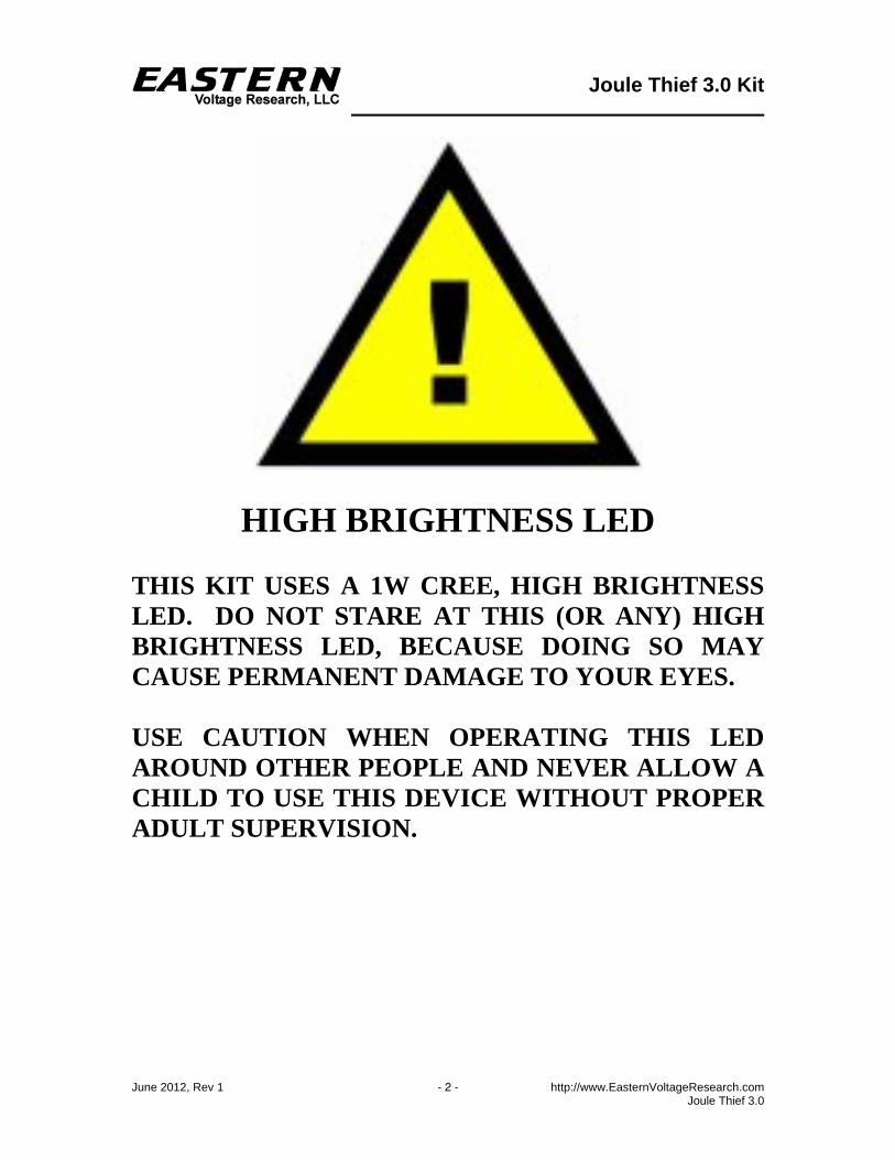
HIGH BRIGHTNESS LED THIS KIT USES A 1W CREE, HIGH BRIGHTNESS LED. DO NOT STARE AT THIS (OR ANY) HIGH BRIGHTNESS LED, BECAUSE DOING SO MAY CAUSE PERMANENT DAMAGE TO YOUR EYES. USE CAUTION WHEN OPERATING THIS LED AROUND OTHER PEOPLE AND NEVER ALLOW A CHILD TO USE THIS DEVICE WITHOUT PROPER ADULT SUPERVISION.
Joule Thief 3.0 Kit
June 2012, Rev 1 − 3 − http://www.EasternVoltageResearch.com Joule Thief 3.0
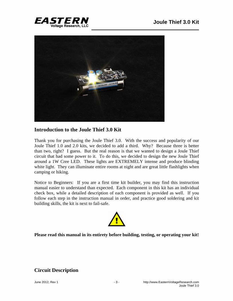
Introduction to the Joule Thief 3.0 Kit Thank you for purchasing the Joule Thief 3.0. With the success and popularity of our Joule Thief 1.0 and 2.0 kits, we decided to add a third. Why? Because three is better than two, right? I guess. But the real reason is that we wanted to design a Joule Thief circuit that had some power to it. To do this, we decided to design the new Joule Thief around a 1W Cree LED. These lights are EXTREMELY intense and produce blinding white light. They can illuminate entire rooms at night and are great little flashlights when camping or hiking. Notice to Beginners: If you are a first time kit builder, you may find this instruction manual easier to understand than expected. Each component in this kit has an individual check box, while a detailed description of each component is provided as well. If you follow each step in the instruction manual in order, and practice good soldering and kit building skills, the kit is next to fail-safe.
Please read this manual in its entirety before building, testing, or operating your kit!
Circuit Description
Joule Thief 3.0 Kit
June 2012, Rev 1 − 4 − http://www.EasternVoltageResearch.com Joule Thief 3.0
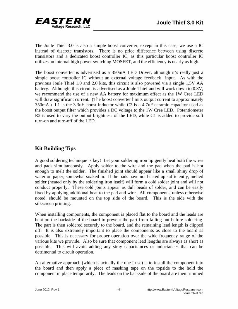
The Joule Thief 3.0 is also a simple boost converter, except in this case, we use a IC instead of discrete transistors. There is no price difference between using discrete transistors and a dedicated boost controller IC, as this particular boost controller IC utilizes an internal high power switching MOSFET, and the efficiency is nearly as high. The boost converter is advertised as a 350mA LED Driver, although it’s really just a simple boost controller IC without an external voltage feedback input. As with the previous Joule Thief 1.0 and 2.0 kits, this circuit is also powered via a single 1.5V AA battery. Although, this circuit is advertised as a Joule Thief and will work down to 0.8V, we recommend the use of a new AA battery for maximum effect as the 1W Cree LED will draw significant current. (The boost converter limits output current to approximately 350mA.) L1 is the 3.3uH boost inductor while C2 is a 4.7uF ceramic capacitor used as the boost output filter which provides a DC voltage to the 1W Cree LED. Potentiometer R2 is used to vary the output brightness of the LED, while C1 is added to provide soft turn-on and turn-off of the LED. Kit Building Tips A good soldering technique is key! Let your soldering iron tip gently heat both the wires and pads simultaneously. Apply solder to the wire and the pad when the pad is hot enough to melt the solder. The finished joint should appear like a small shiny drop of water on paper, somewhat soaked in. If the pads have not heated up sufficiently, melted solder (heated only by the soldering iron itself) will form a cold solder joint and will not conduct properly. These cold joints appear as dull beads of solder, and can be easily fixed by applying additional heat to the pad and wire. All components, unless otherwise noted, should be mounted on the top side of the board. This is the side with the silkscreen printing. When installing components, the component is placed flat to the board and the leads are bent on the backside of the board to prevent the part from falling out before soldering. The part is then soldered securely to the board, and the remaining lead length is clipped off. It is also extremely important to place the components as close to the board as possible. This is necessary for proper operation over the wide frequency range of the various kits we provide. Also be sure that component lead lengths are always as short as possible. This will avoid adding any stray capacitances or inductances that can be detrimental to circuit operation. An alternative approach (which is actually the one I use) is to install the component into the board and then apply a piece of masking tape on the topside to the hold the component in place temporarily. The leads on the backside of the board are then trimmed
Joule Thief 3.0 Kit
June 2012, Rev 1 − 5 − http://www.EasternVoltageResearch.com Joule Thief 3.0
leaving about 0.10” lead protruding through the backside of the board, and then soldered from the backside. You can then remove the masking tape, and finally apply a small amount of solder on the top to complete the joint on both sides. This is shown in the figure below.
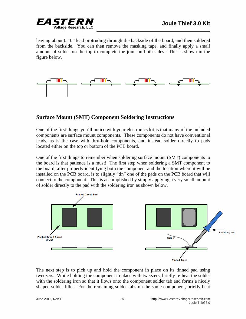
Surface Mount (SMT) Component Soldering Instructions One of the first things you’ll notice with your electronics kit is that many of the included components are surface mount components. These components do not have conventional leads, as is the case with thru-hole components, and instead solder directly to pads located either on the top or bottom of the PCB board. One of the first things to remember when soldering surface mount (SMT) components to the board is that patience is a must! The first step when soldering a SMT component to the board, after properly identifying both the component and the location where it will be installed on the PCB board, is to slightly “tin” one of the pads on the PCB board that will connect to the component. This is accomplished by simply applying a very small amount of solder directly to the pad with the soldering iron as shown below.
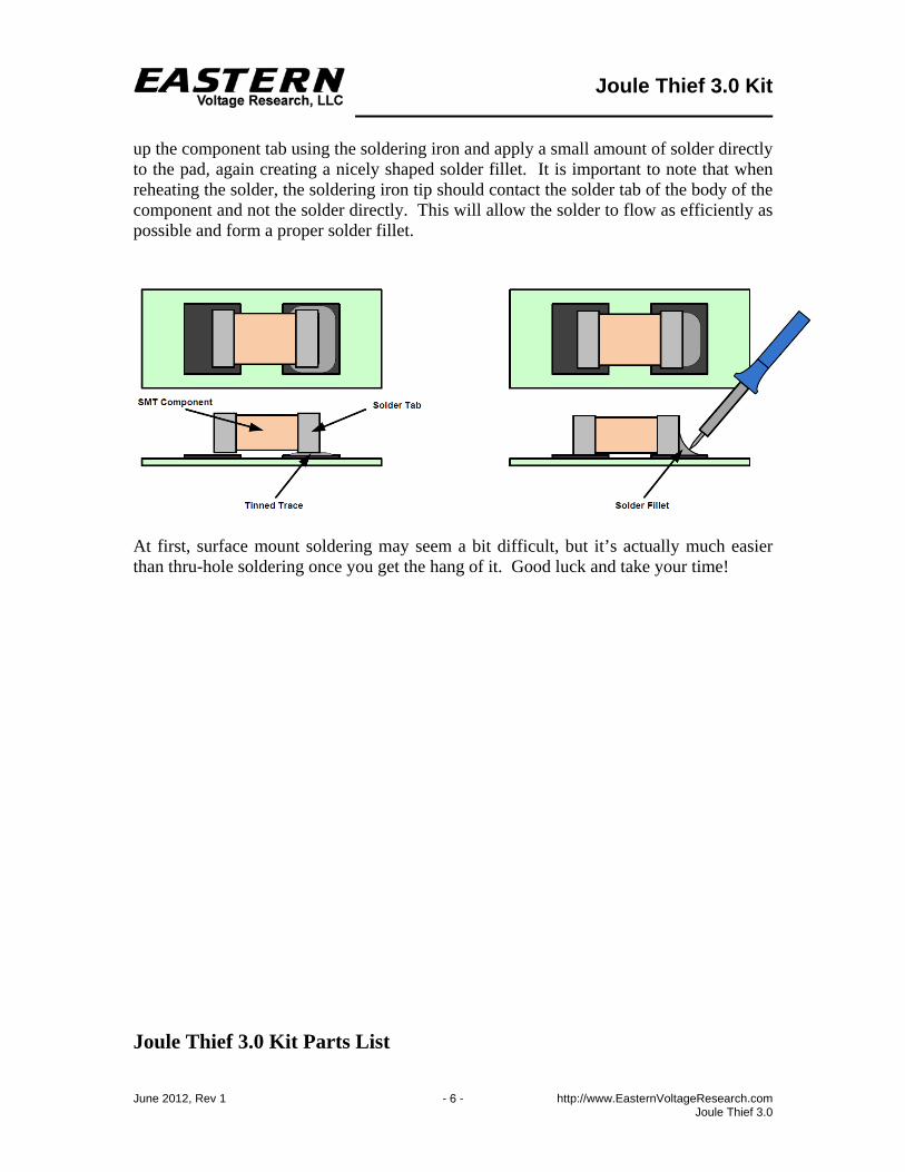
The next step is to pick up and hold the component in place on its tinned pad using tweezers. While holding the component in place with tweezers, briefly re-heat the solder with the soldering iron so that it flows onto the component solder tab and forms a nicely shaped solder fillet. For the remaining solder tabs on the same component, briefly heat
Joule Thief 3.0 Kit
June 2012, Rev 1 − 6 − http://www.EasternVoltageResearch.com Joule Thief 3.0
up the component tab using the soldering iron and apply a small amount of solder directly to the pad, again creating a nicely shaped solder fillet. It is important to note that when reheating the solder, the soldering iron tip should contact the solder tab of the body of the component and not the solder directly. This will allow the solder to flow as efficiently as possible and form a proper solder fillet.
At first, surface mount soldering may seem a bit difficult, but it’s actually much easier than thru-hole soldering once you get the hang of it. Good luck and take your time! Joule Thief 3.0 Kit Parts List
Joule Thief 3.0 Kit
June 2012, Rev 1 − 7 − http://www.EasternVoltageResearch.com Joule Thief 3.0
RESISTORS 2 0 ohm Resistor, 0805, R1,R3 1 1 Meg, Potentiometer, Single Turn, R2 CAPACITORS 1 1uF Capacitor, Ceramic, 0805, C1 (smaller of the chip capacitors) 1 4.7uF Capacitor, Ceramic, 1206, C2 (larger of the chip capacitors) DIODES 1 LED, Cree, Xlamp, 1W, White, D1 1 Diode, MBRM120E, CR1 (OPTIONAL) SEMICONDUCTORS 1 Booster Converter IC, 1W LED Driver IC, 8-SOIC, U1 MISCELLANEOUS 1 Inductor, 3.3uH, L1 1 Switch, Slide, SW1 2 AA Battery Clips, BAT1 1 PCB Board, Joule Thief 3.0 1 Schematic, Joule Thief 3.0 REQUIRED, NOT SUPPLIED 1 AA Battery, BAT1
Joule Thief 3.0 Kit
June 2012, Rev 1 − 8 − http://www.EasternVoltageResearch.com Joule Thief 3.0
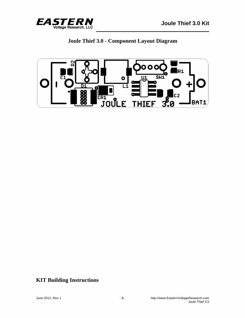
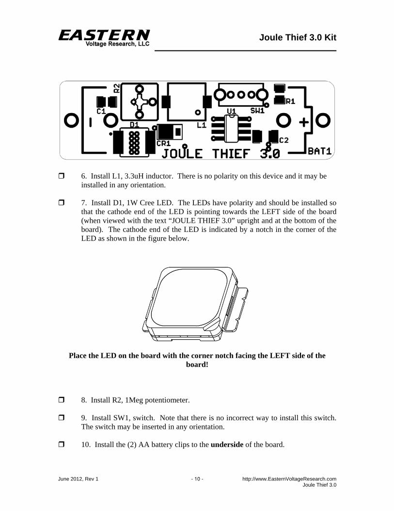
Joule Thief 3.0 - Component Layout Diagram
KIT Building Instructions
Joule Thief 3.0 Kit
June 2012, Rev 1 − 9 − http://www.EasternVoltageResearch.com Joule Thief 3.0
Now we will begin building the kit. There are just a few more important things to know before we install the first components. For each component, the word “install” always means the following: 1. Pick the correct value to start with. 2. Insert the component into the correct printed circuit board (PCB) location. 3. Orient the component correctly – especially when there is a right and a wrong
way to solder it in. (i.e. Electrolytic capacitors, diodes, ICs, transistors, etc…) 4. Solder all connections unless directed otherwise. Ensure enough heat is used to
allow solder to flow for clean, shiny, and completed connections. Also, please be sure to take us seriously when we say that good soldering is the key to the proper operation of your circuit!
Use a 25W soldering pencil with a clean, sharp tip. DO NOT USE a high power soldering gun such as those trigger activated units.
Use only rosin core solder intended for electronics use Ensure your work area is clean, and has plenty of bright lighting Build your kit in stages, taking breaks to check your work. Be sure to clean the
board periodically with a brush or compressed air to remove any excess wire cuttings, etc…
Okay, so let’s begin! 1. Install R1, 0.0 ohm resistor (marking 0R0 or similar) 2. Install R3, 0.0 ohm resistor (marking 0R0 or similar). Note, this resistor is located on the bottom side of the board. There is no silkscreen designation for this part – it is just a single resistor location with two pads on the bottom side of the board. 3. Install C1, 1uF, 0805 capacitor. This capacitor does not have a marking but is the smaller of the two capacitors provided. 4. Install C2, 4.7uF, 1206 capacitor. This capacitor does not have a marking but is the larger of the two capacitors provided. 5. Install, U1, Booster Converter LED Driver IC. Note that one side of the IC has a top edge that is chamfered. This designates the side that Pin 1 is on. This side must be oriented correctly when installed as shown in the layout view below.
Joule Thief 3.0 Kit
June 2012, Rev 1 − 10 − http://www.EasternVoltageResearch.com Joule Thief 3.0
6. Install L1, 3.3uH inductor. There is no polarity on this device and it may be installed in any orientation. 7. Install D1, 1W Cree LED. The LEDs have polarity and should be installed so that the cathode end of the LED is pointing towards the LEFT side of the board (when viewed with the text “JOULE THIEF 3.0” upright and at the bottom of the board). The cathode end of the LED is indicated by a notch in the corner of the LED as shown in the figure below.
Place the LED on the board with the corner notch facing the LEFT side of the
board! 8. Install R2, 1Meg potentiometer. 9. Install SW1, switch. Note that there is no incorrect way to install this switch.
The switch may be inserted in any orientation. 10. Install the (2) AA battery clips to the underside of the board.
Joule Thief 3.0 Kit
June 2012, Rev 1 − 11 − http://www.EasternVoltageResearch.com Joule Thief 3.0
Congratulations! You have just completed your Joule Thief 3.0 kit. Please take a few moments to look over the board and ensure that all the components are installed properly with the correct orientation. Since some of the parts may be unfamiliar to you, you may want to be extra sure that they have been inserted correctly. After you are sure that everything seems to be properly installed, move on to the set-up and testing section.
HIGH BRIGHTNESS LED WARNING
DO NOT STARE at high brightness LEDs. Doing so may cause permanent damage to your eyes.
Set-up and Testing Okay, so let’s begin! 1. Using a small screw driver, adjust the potentiometer in the clockwise rotation
until it’s at its maximum adjustment position. This will set the LED for maximum brightness.
2. With the LED facing away from you, install an AA battery into the battery
clips. Make sure the battery is installed with the correct polarity. The LED may turn on at this time depending on what position the switch is.
3. Turn the switch to the ON position if the LED is not already illuminated. 4. To vary the brightness of the LED, adjust the potentiometer as needed. Congratulations! Your Joule Thief 3.0 is now completed and operational.
Joule Thief 3.0 Kit
June 2012, Rev 1 − 12 − http://www.EasternVoltageResearch.com Joule Thief 3.0
Using RED LEDs If you wish to use a high output red LED instead of the provided the white LED, you will need to make a few modifications to the board. These changes are required as the forward voltage drop of a red LED is significantly lower than that of a white LED. The addition of the MBRM120ET3 schottky diode adds about a 0.5V forward voltage drop to the output string. 1. Remove white LED – re-install a red LED 2. Remove R3 (0.0 ohm, 0805 resistor) from the bottom side of the board. 3. Install a MBRM120ET3 schottky diode (not supplied) in the CR1 location. Soft Turn-ON / Turn-OFF Functionality 1uF capacitor, C1 provides the soft turn-on / turn-off functionality of the circuit. To remove this soft turn-on / turn-off, simply remove C1. If you wish to modify the characteristics of the turn-on / turn-off, you can use a different value capacitor. Lower values will reduce the soft turn-on / turn-off times, while larger values will increase the soft turn-on / turn-off times. Troubleshooting PROBLEM: The LEDs do not illuminate when I turn the switch ON. SOLUTION: Verify that the LED and U1 are installed correctly, the battery is installed correctly, and that the battery is not completely drained. PROBLEM: The LEDs illuminate very dimly or intermittently. SOLUTION: The battery may be discharged below the 0.8V required for this circuit to operate correctly. Be sure to use a new AA battery for best performance.
Conclusion

Joule Thief 3.0 Kit
June 2012, Rev 1 − 13 − http://www.EasternVoltageResearch.com Joule Thief 3.0
We sincerely hope that you have enjoyed the construction of this Eastern Voltage Research Kit. As always, we have tried to write this instruction manual in the easiest, most “user friendly” format that is possible. As our customers, we value your opinions, comments, and additions that you would like to see in future publications. Please submit comments or ideas to: Eastern Voltage Research, LLC Technical Support [email protected] Thanks again from the people here at Eastern Voltage Research. Terms and Conditions of Sale Before opening or assembling your kit, please read and review the latest Terms and Conditions of Sale on our website at the following link: http://www.easternvoltageresearch.com/terms.html