Embed Size (px)
Citation preview

JOSEPH MUGFORD THESIS PRESENTATION SPRING 2007
SOHO SOHO
HIGH RISE HIGH RISE
CONDOMINIUMCONDOMINIUMSS
A STUDY OF LIGHTWEIGHT CONCRETE CONSTRUCTION
JOSEPH MUGFORD THESIS PRESENTATION SPRING 2007
Location and Architecture

JOSEPH MUGFORD THESIS PRESENTATION SPRING 2007
Location and ArchitectureLocation and Architecture
SOHO, NY,NY
Trendy urban Neighborhood of Downtown Manhattan
Simple geometric shapes create areas of transparency, light and shadow
Sleek horizontal and vertical lines provide a rigid architectural grid for the building façade, a combination of colored and transparent glass
“This is a way to live at this time, in the poetry of the neighborhood. The emotion of architecture is linked to this harmony, to this relationship.”Jean Nouvel, Architect

JOSEPH MUGFORD THESIS PRESENTATION SPRING 2007
Location and ArchitectureLocation and Architecture
Project Team
Owner: WXIV/Broadway Grand
Architect of Record: SLCE Architects
Design Architect: AJN Ateliers Jean Nouvel
Structural Engineers: Gilsanz.Murray.Steficek.LLP
MEP Engineers: Cosentini Associates
Curtain Wall Consultants: Gilsanz.Murray.Steficek.LLP
Landscape Architect: Thomas Balsley Associates
Lighting Consultant: Johnson Schwinghammer Inc.
General Contractor: Pavarini Construction Co. Inc.
15 Story Condominium ComplexHeight: 175’
Base: 70’ X 200’
Tower: 33’ X 170’
Sub-Cellar Parking
Cellar Fitness and Spa
1st Floor Retail
10,000 SF
2-5: 27 Residential Units
11,800 SF/Floor
6-12: 13 Residential Units
4,650 SF/Floor
12-13: 2 Penthouse Units
6th Floor Roof Terrace

JOSEPH MUGFORD THESIS PRESENTATION SPRING 2007
Existing Structure

JOSEPH MUGFORD THESIS PRESENTATION SPRING 2007
Existing StructureExisting Structure
Floor Plans
10 ½” Flat Plate
Uniform Steel
#4 @12” o.c. bot. ea. way
#5@16” o.c. top ea. Way
Significant additional steel at column locations

JOSEPH MUGFORD THESIS PRESENTATION SPRING 2007
Existing StructureExisting Structure
Lateral System
Base Thru 5th
6th Thru 13th

JOSEPH MUGFORD THESIS PRESENTATION SPRING 2007
Structural Depth

JOSEPH MUGFORD THESIS PRESENTATION SPRING 2007
Structural DepthStructural Depth
LWC FLAT PLATE DESIGN GOALS & STRATEGY
Minimize usage of structural materials to offset the premium of LWC
1. Deflection equations derived by R.I. Gilbert
2. Add edge beams at building corners to support reduced slab
1. Elements that are more efficient in bending
Offset reduced gravity loads
2. Uniform Cross section throughout height of building
Consistent formwork
Efficient load path with limited number of vertical discontinuities
Reduce Slab Thickness
Re-Design Shear Wall Core

JOSEPH MUGFORD THESIS PRESENTATION SPRING 2007
Structural DepthStructural Depth
Materials
Floor Slabs
Shear Walls
4 ksi NWC
5 ksi NWC
4 ksi LWC
5 ksi NWC
Existing System
New System

JOSEPH MUGFORD THESIS PRESENTATION SPRING 2007
Structural DepthFlat Plate

JOSEPH MUGFORD THESIS PRESENTATION SPRING 2007
Structural DepthStructural Depth
LWC VS. NWC
BENEFITSBetter acoustical performance
Better thermal properties
Higher fire resistance
Reduced autogeneous shrinkage
Improved contact zone between aggregate and concrete matrix
less micro-cracking as a result of better elastic compatibility
Higher blast resistance
Recycled additatives (fly ash, etc.)
SIGNIFICANT WEIGHT REDUCTION
-”Structural Lightweight Concrete”
Expanded Shale Clay and Slate Institute
COSTS$20-30/ Cu. YD premium
compressive strengths exceeding 4 ksi not available
Alternative design and detailing to NWC

JOSEPH MUGFORD THESIS PRESENTATION SPRING 2007
Structural DepthStructural Depth
DEFLECTION RESEARCH AND APPLICATION
Gilbert-85Modification of Branson Beam Equation
onModificati Deflection Term Longc
Load Sustainedw
Load Variablew
Beam Equivalentby CarriedFraction Loadk
Elasticity of ModulusE
WidthEffectiveb
s
v
c
eff
nand
K
K
K
ofEffect
Deflection Maximum
Factor System Slab
Factor Shape
FactorSupport
3
2
1
= 9” Slab Depth
1.3
1.0 15√ρn1.0
2.0-1.2As’/As
*sustained loading includes 50% live load

JOSEPH MUGFORD THESIS PRESENTATION SPRING 2007
Structural DepthStructural Depth
DEFLECTION RESEARCH AND APPLICATION
Gilbert-99Modification of current ACI deflection equation
β accounts for tension cracking resulting from shrinkage and long term loading
Computed deflection multiplied by λ per ACI 318 (2.0 for long term loading)
= l /390
0.4 (long term loading)

JOSEPH MUGFORD THESIS PRESENTATION SPRING 2007
Structural DepthStructural Depth
COLUMN TRANSFER
Transfer Forces
Moment=5434’k
Shear=253k
Shear Transfer Reinforcement
8-#7 @ Transfer walls
10-#7 @ Shear walls

JOSEPH MUGFORD THESIS PRESENTATION SPRING 2007
Structural DepthStructural Depth
LWC FLAT PLATE DESIGN

JOSEPH MUGFORD THESIS PRESENTATION SPRING 2007
Structural DepthStructural Depth
LWC FLAT PLATE DESIGN

JOSEPH MUGFORD THESIS PRESENTATION SPRING 2007
Structural DepthStructural Depth
LWC FLAT PLATE DESIGN
Design Slab depth=9”
Uniform Reinforcement
#5@16” o.c. bottom ea. way
#5@12” o.c. top ea. way
Equivalent Frame Method
Cantilever Beams
Column Transfer
12X28 cantilever beams at building cornersCorner columns increase to 20 x 32 @ Base
Additional 8-#7 @Gravity WallAdditional 10-#7 @Shear Wall

JOSEPH MUGFORD THESIS PRESENTATION SPRING 2007
Structural DepthLateral System

JOSEPH MUGFORD THESIS PRESENTATION SPRING 2007
Structural DepthStructural Depth
SHEAR WALL DESIGN CRITERIA
Lateral forces
ASCE 7-05 Method 2
ASCE 7-05 Equivalent Lateral Force Procedure (ELF)
Dynamic analysis (ETABS)
Deflection
Total Building Drift H/500 (Wind)
Total Building Drift H/400 (Seismic)
Wind
Earthquake
Shear From Column Transfer

JOSEPH MUGFORD THESIS PRESENTATION SPRING 2007
Structural DepthStructural Depth
N-S Wind Controls
N/S E/W N/S E/W N/S E/WRoof 26 5 0 0 4,348 84612 48 9 26 5 7,455 1,44311 45 9 75 15 6,382 1,23510 44 9 120 23 5,712 1,1019 43 8 165 32 5,038 9658 43 8 208 40 4,521 8667 42 8 251 48 3,890 7406 64 10 293 56 5,200 8405 79 25 357 67 5,426 1,7364 79 25 436 92 4,354 1,3843 61 19 515 117 2,381 7452 59 18 577 136 1,524 4711 66 20 636 155 853 256
Totals 702 174 702 174 57,083 12,626
Moment (ft-k)Level
Load (k) Shear (k)

JOSEPH MUGFORD THESIS PRESENTATION SPRING 2007
Structural DepthStructural Depth
E-W Seismic Controls
Modal (Dynamic) AnalysisResponse Spectrum
Base Shear=386 K (ELF)R=4 (Normally Reinforced Shear Walls)
Element Stiffness
modified to account for cracking of concrete and force distribution
Walls=0.7Ig (uncracked)
Coupling Beams=0.35Ig
T=2.06s
IBC 2000 Function scaled to NYC SDS &SD1

JOSEPH MUGFORD THESIS PRESENTATION SPRING 2007
Structural DepthStructural Depth
Story Displacements
Story Load ΔX ΔY Story Load ΔX ΔYBH 2 WINDX 0.75 0.00 STORY 8 WINDX 0.37 0.00BH 2 Quake X 3.03 0.13 STORY 8 Quake X 1.37 0.00BH 2 WINDY 0.08 4.04 STORY 8 WINDY 0.01 1.62BH 2 QUAKE Y 0.07 3.50 STORY 8 QUAKE Y 0.01 1.32BH 1 WINDX 0.75 -0.01 STORY 7 WINDX 0.32 0.00BH 1 Quake X 3.03 -0.16 STORY 7 Quake X 1.14 0.00BH 1 WINDY 0.08 3.48 STORY 7 WINDY 0.01 1.32BH 1 QUAKE Y 0.07 2.98 STORY 7 QUAKE Y 0.01 1.07
ROOF WINDX 0.71 0.00 STORY 6 WINDX 0.26 0.00ROOF Quake X 2.84 0.02 STORY 6 Quake X 0.89 0.00ROOF WINDY 0.02 3.60 STORY 6 WINDY -0.04 1.04ROOF QUAKE Y 0.02 3.10 STORY 6 QUAKE Y -0.03 0.83
STORY 13 WINDX 0.66 0.00 STORY 5 WINDX 0.20 0.00STORY 13 Quake X 2.62 0.00 STORY 5 Quake X 0.65 0.00STORY 13 WINDY 0.02 3.25 STORY 5 WINDY -0.03 0.74STORY 13 QUAKE Y 0.02 2.79 STORY 5 QUAKE Y -0.02 0.59STORY 12 WINDX 0.60 0.00 STORY 4 WINDX 0.13 0.00STORY 12 Quake X 2.36 0.00 STORY 4 Quake X 0.40 0.00STORY 12 WINDY 0.02 2.90 STORY 4 WINDY -0.02 0.45STORY 12 QUAKE Y 0.01 2.47 STORY 4 QUAKE Y -0.01 0.35STORY 11 WINDX 0.54 0.00 STORY 3 WINDX 0.07 0.00STORY 11 Quake X 2.12 0.00 STORY 3 Quake X 0.23 0.00STORY 11 WINDY 0.01 2.57 STORY 3 WINDY -0.01 0.25STORY 11 QUAKE Y 0.01 2.17 STORY 3 QUAKE Y -0.01 0.19STORY10 WINDX 0.49 0.00 STORY 2 WINDX 0.03 0.00STORY10 Quake X 1.87 0.00 STORY 2 Quake X 0.09 0.00STORY10 WINDY 0.01 2.25 STORY 2 WINDY 0.00 0.10STORY10 QUAKE Y 0.01 1.88 STORY 2 QUAKE Y 0.00 0.07STORY 9 WINDX 0.43 0.00STORY 9 Quake X 1.62 0.00STORY 9 WINDY 0.01 1.93STORY 9 QUAKE Y 0.01 1.60

JOSEPH MUGFORD THESIS PRESENTATION SPRING 2007
Structural DepthStructural Depth
Lateral System ModificationBase Thru
5th
6th Thru 13th

JOSEPH MUGFORD THESIS PRESENTATION SPRING 2007
Structural DepthStructural Depth

JOSEPH MUGFORD THESIS PRESENTATION SPRING 2007
LEED Breadth

JOSEPH MUGFORD THESIS PRESENTATION SPRING 2007
LEED BreadthLEED Breadth
“A green building is one whose construction and lifetime of operation assure the healthiest possible environment while representing the most efficient and least disruptive use of land, water, energy and resources. The optimum design solution is one that effectively emulates all of the natural systems and conditions of the pre-developed site – after development is complete.”
-Zeigler
Design Goal
Gain LEED Certification of the SOHO High Rise (Implement 26/69 LEED Criteria):
Acknowledge criteria already met
Identify additional suitable criteria and associated costs

JOSEPH MUGFORD THESIS PRESENTATION SPRING 2007
LEED BreadthLEED Breadth
Water Efficiency
Water Efficency Worksheet Daily Uses Flow Rate Duration Residents Water Use
Flush Fixture (GPF) (Flushes) (GPD)Conventional Water Closet (M & F) 3 1.6 1 132 634Low Flush Water Closet (M & F) 3 1 1 132 396
Flow Fixture (GPM) (Sec)Conventional Lavoratory 3 2.5 12 132 198Conventional Kitchen Sink 1 2.5 12 132 66Conventional Shower 1 2.5 180 132 990Laminar Flow Lavoratory 3 1.8 12 132 143Laminar Flow Kitchen Sink 1 1.8 12 132 48Laminar Flow Shower 1 1.8 180 132 713
18881299
Assumptions %reduction 313 occupants per condominium44 Total Condominiums
Convemtional Water UseEfficent Water Use
JOSEPH MUGFORD THESIS PRESENTATION SPRING 2007
LEED BreadthLEED Breadth
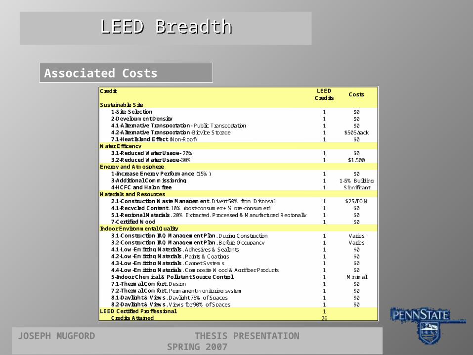
Associated Costs Credit
Sustainable Site1-Site Selection 1 $0 2-Development Density 1 $0 4.1-Alternative Transportation- Public Transportation 1 $0 4.2-Alternative Transportation-Bicylce Storage 1 $505/rack7.1-Heat Island Effect (Non-Roof) 1 $0
Water Efficency3.1-Reduced Water Usage- 20% 1 $0 3.2-Reduced Water Usage-30% 1 $1,500
Energy and Atmosphere1-Increase Energy Performance (15%) 1 $0 3-Additional Commissioning 1 1-5% Building4-HCFC and Halon free 1 Significant
Materials and Resources2.1-Construction Waste Management, Divert 50% from Disposal 1 $25/TON4.1-Recycled Content, 10% (post-consumer + ½ pre-consumer) 1 $0 5.1-Regional Materials, 20% Extracted, Processed & Manufactured Regionally 1 $0 7-Certified Wood 1 $0
Indoor Environmental Quality3.1-Construction IAQ Management Plan, During Construction 1 Varies3.2-Construction IAQ Management Plan, Before Occupancy 1 Varies4.1-Low-Emitting Materials, Adhesives & Sealants 1 $0 4.2-Low-Emitting Materials, Paints & Coatings 1 $0 4.3-Low-Emitting Materials, Carpet Systems 1 $0 4.4-Low-Emitting Materials, Composite Wood & Agrifiber Products 1 $0 5-Indoor Chemical & Pollutant Source Control 1 Minimal7.1-Thermal Comfort, Design 1 $0 7.2-Thermal Comfort, Permanent monitoring system 1 $0 8.1-Daylight & Views, Daylight 75% of Spaces 1 $0 8.2-Daylight & Views, Views for 90% of Spaces 1 $0
LEED Certified Proffessional 1Credits Attained 26
LEED Credits
Costs

JOSEPH MUGFORD THESIS PRESENTATION SPRING 2007
Conclusions and Recommendations

JOSEPH MUGFORD THESIS PRESENTATION SPRING 2007
Conclusions and Conclusions and RecommendationsRecommendations
Structural13-18% Reduction of Column Service Loads ~4500K
8-10% Reduction in Slab Reinforcement
19 ½” Total Height Reduction
25% Reduction of Seismic Base Shear
Applicable to high seismic regions
Uniformity of shear wall system
Predictable lateral response
Consistent formwork
*Does not include possible column cross section reduction
Existing Redesign ComparisonCost Cost
Base Concrete $228,165 $232,875 $4,710Rebar $283,700 $259,780 $23,921
Cantilevers $0 $33,198 $33,198Tower Concrete $140,175 $143,125 $2,950
Rebar $174,335 $159,615 $14,720Cantilevers $0 $53,116 $53,116
Walls Concrete $109,984 $121,072 $11,088Rebar $64,455 $119,472 $55,016
Coupling Beams$92,039 $77,428 $14,611
$106,826
Shear Walls
Flat Plate
Cost Increase
ArchitecturalElimination of shear wall section provides for architecturally free floor plan
Lower gravity loads may increase sellable floor area by reducing column cross sections

JOSEPH MUGFORD THESIS PRESENTATION SPRING 2007
Conclusions and Conclusions and RecommendationsRecommendations
It should be the goal of developers and designers to implement design solutions that not only provide low first cost, but also improve the world and environments we live in.
LEED
Implement additional LEED criteria that benefit occupants and meet allowable development budget
Certification carries significant cost and schedule implications
Notable social status symbol

JOSEPH MUGFORD THESIS PRESENTATION SPRING 2007
Questions?

JOSEPH MUGFORD THESIS PRESENTATION SPRING 2007
AE Faculty
GMS.LLP
SLCE ARCHITECTS
FAMILY & FRIENDS
THANK YOU