Embed Size (px)
Citation preview

THE UNIVERSITY OF ALBERTA
THE USE OF GROUTING FOR SEEPAGE CONTROL
THROUGH FOUNDATIONS OF DAMS ON
BEDROCK - A REVIEW
by
JOSE CARLOS ROSA
A REPORT
SUBMITTED TO THE FACULTY OF GRADUATE STUDIES AND RESEARCH I N
PARTIAL FULFILMENT OF THE REQUIREMENTS FOR THE DEGREE
OF MASTER OF ENGINEERING
DEPARTMENT OF C I V I L ENGINEERING
EDMONTON, ALBERTA
SPRING, 1980

ACKNOWLEDGEMENTS
The r e s e a r c h r e p o r t e d i n t h i s work was c a r r i e d
o u t a t t h e Department o f C i v i l Engineer ing , U n i v e r s i t y of
A l b e r t a , under t h e s u p e r v i s i o n of P r o f e s s o r Z . E i s e n s t e i n .
T h e a u t h o r i s indeb ted t o P r o f e s s o r Z . E i s e n s t e i n f o r h i s
con t inued guidance and encouragement t h r o u g h o u t t h e p e r i o d
of work.
S i n c e r e s t ' thanks a r e exp res sed t o P r o f e s s o r N.R.
.Morgenstern f o r h i s suppor t and encouragement, and f o r h i s
sugges t ions on t h e s u b j e c t o f t h e r e p o r t .
The au tho r i s g r a t e f u l to M r . Raymond S tewar t
f o r h i s a s s i s t a n c e i n t h e p r e p a r a t i o n o f t h e r e p o r t , a n d f o r
h i s d i s c u s s i o n s on v a r i o u s a s p e c t s r e l a t e d to t h e r e s e a r c h
The a u t h o r i s g r a t e f u l t o t h e U n i v e r s i t y o f
A l b e r t a f o r p rov id ing him f i n a n c i a l suppor t d u r i n g t h e
p e r i o d of t h e s tudy .
The r e p o r t was typed by M i s s Zu le ica Madalena
C a c i n i , whose c a r e f u l work is a p p r e c i a t e d .

TABLE OF CONTENTS
CHAPTER PAGE
I INTRODUCTION ............................ I1 THE NEED FOR GROUTING DAM FOUNDATION ....
2.1 General Considerations ............. 2.2 Usual Criteria for Appraisal of the
Need for Grouting ................. 2.3 Criticism of the Existing Criteria .. 2.4 Suggested Criteria for Evaluating
the Necessity of a Grout Curtain ... 2.5 Considerations Regarding Safety of ........ Dams as Related to Grouting
..... . I11 TYPES OF GROUTING A GENERAL VIEW
3.1 General ......................... 3.2 The Corps of Engineering Classifica-
tion .......................... ......... 3.3 The "Usual" Classification
IV GROUTING METHODS .................... ........................... 4.1 General
4.2 Advantages of Stage Grouting ....... 4.3 Advantages of Packer Grouting ......
V TYPES OF GROUT ........................ 5.1 General ......................

CHAPTER PAGE
....... 5.2 Relevant Properties of Grouts 24
5.3 Cement Grouts ....................... 25
5.4 Chemical Grouts ..................... 2 7 '
5.5 Asphalt Grouts ..................... 2 8
5.6 Aerated Grouts ..................... 28
5.7 The Choice of an Appropriate Grout
for a Specific Case ............... 29
VI GROUTING PROCEDURES ..................... 33
6.1 General ......................... 33
6.2 Drilling ........................... 33
.................. 6.3 Grouting Pressure 34
......................... 6.4 Grout Mixes 38
VII THEORETICAL AND EXPERIMENTAL STUDIES ON
GROUTING .............................. 4 1
7.1 General ......................... 41.
.... 7.2 Theoretical Approach to Grouting 4 1
7.3 Experiments on Grouting .......... 4 4
VIII GROUTING DESIGN ......................... 48
8.1 General ............................. 48
8.2 Required Input Data for Grouting Design ............................ 48
8.3 Geometrical Characteristics of the Grout Curtain ..................... 49
8.4 Guides on Grouting Pressures. Grout Mixes and Method to be Followed ..... 58
8.5 Estimation of Grout Takes ........... 59

CHAPTER PAGE
IX APPRAISAL OF THE EFFECTIVENESS OF A GROUT CURTAIN ...................
............................. 9.1 General
9.2 Methods for Evaluation of the Perfor- mance of Grout Curtains ..............
........................... X CASE HISTORIES
10-1 General ............................ ................. 10-2 Charmine Dam. France
................... 10.3 Hales Bar Dam. USA
10-4 Portage Mountain Dam. British Columbia . BIBLIOGRAPHY .................................

LIST OF FIGURES
FIGURE PAGE -
Cutoff
Upstream Impervious Blanket
Hor i zon ta l Drain
R e l i e f Wells
Arrangement o f t h e wate r p r e s s u r e t e s t u s i n g a '
s i n g l e packer
V a r i a t i o n o f t h e p e r m e a b i l i t y w i t h f r a c t u r e wid th
P e r c o l a t i o n v s p r e s s u r e diagrams
Example o f a j o i n t set c o n s i s t i n g o f 5 j o i n t s o f v a r i o u s a p e r t u r e s , roughnesses and s p a c i n g s
Typica l arrangement of a packer g r o u t i n g i n s t a l l a t i o n
S t age g r o u t i n g
I n j e c t i o n o f a mixture grout-sawdust
Suggest ion f o r g r o u t i n g o f f i s s u r e s i n l imes tone
Grout ing p r e s s u r e x dep th . Comparative graph
Formation o f a j o i n t under h igh g r o u t i n g p r e s s u r e
I n j e c t i o n of a f i s s u r e
D i s t r i b u t i o n o f p r e s s u r e a long t h e f i s s u r e
F i s s u r e g r o u t i n g
E q u i p o t e n t i a l s and f l o w l i n e s i n a bo reho le d u r i n g
Device used by t h e U.S. Corps of Engineers f o r g r o u t i n g t e s t s
P o s i t i o n of t h e Grout C u r t a i n
P l a n V i e w o f t h e Grout C u r t a i n
Grout c u r t a i n under dams w i t h upstream membranes
P o s i t i o n o f t h e under a conc r&te g r a v i t y dam
Cracks under an a r c h dam
Design proposed by Saba r ly
Suggested c o n f i g u r a t i o n f o r g r o u t h o l e s when d i s t i n c t s t r a t a occur
P l a n mul t i row grouted c u t o f f

I n c l i n e d Grout C u r t a i n
Fan - W i s e g r o u t c u r t a i n
S p l i t - Spacing Technnique
R e l a t i o n s h i p between g r o u t t a k e and h o l e s p a c i n g , accord ing t o Nonve i l l e r
Grout t a k e x Hole Spacing
Suggested R e l a t i o n s h i p Between Water Take and Grout Take
Piezometer o b s e r v a t i o n s i n pe rv ious rock unde r ly ing e a r t h dam
A Plan V i e w o f Charmine - Dam ~ i ' t e
c o n s t r u c t i o n o f an i n v e r t e d f i l t e r f o r g r o u t i n g f i s s u r e s under charmine Dam
Cross S e c t i o n through t h e Foundat ion under Hales Bar Dam, Facing Upstream
Conf igu ra t ion o f t h e g r o u t h a l e s , a t Hales B a r Dam
Geology a t Po r t age Mountain Dam S i t e
Mul t i row g r o u t c u r t a i n , a t Po r t age Plountain D a m
Secondary p e r m e a b i l i t y o f t h e founda t ion b e f o r e and a f t e r g r o u t i n g , cm/sec., a t Po r t age Mountain Dam

L I S T OF T A B L E S
TABLE
2.1 Es t imated x computed f low o f w a t e r under dams
5.1 Comparative p r i c e s o f g r o u t s
. 6 .1 Sugges t ions f o r g r o u t mixes
9 .1 E f f e c t o f Reduced P e r m e a b i l i t y i n C u r t a i n
10.1 Reduction o f Seepage under CharmineDam
PAGE

CHAPTER 1
INTRODUCTION
The control of seepage through dam foundations is a
feature of paramomtimportance in any dam project. The control
measures most often taken, either jointly or separately, are:
1) cutoffs
2) upstream impervious blankets
3) horizontal drains
4) relief wells
The first two measures are an attempt, which can be
more or less successful, to reduce the rate of seepage through
the foundations, whereas the last two are designed to prevent
high uplift pressures under the dam, and besides, to prevent
piping through the foundations. The later two measures may even
cause an increase in the total seepage loss. The figures below
illustrate the above mentioned solutions:
Fig.l.1 CUTOFF
(after Wahlstrom)
-- - -- UPSTREAM IMPERVIWS r_ = - . BLANKET .. . .
4. ..:... --.---.- . . . ..... -:. . . . . . . .~ (a£ ter Wahlstrom) :.-::::.:. . ~ -d

Fig. 1.3 HORIZONTAL DRAIN (after Sherard)
Fig.l.4
RELIEF WELLS (Af ter Sherard)
The first procedure listed, cutoff construction can
be effective, depending on the type of cutoff used. Cutoffs can
be either partial or complete. The types more often used are:
- excavated trench, filled with impervious soil - sheet pile wall - concrete trench - slurry trench - grout curtain Whnthe dam foundation is on bedrock, the first four
types are either difficult to construct or too expensive,or both.
For example, a sheet pile wall generally cannot be driven into
bedrock and trenches would probably have to be excavated using
explosives. This would be too expensive and may be dangkrous ,
due to cracking induced by the excavation method. The efkctive-
ness of horizontal blankets in the reduction of seepage is doubt-
full and dependent on the silting of the reservoir area.

Therefore, when the dam foundation is on bedrock the
only suitable seepage reduction method left is grouting.
Since grouting is, from a practical point of wiew,
the only method suitable for seepage reduction beneath a dam in . a rock foundation, this method has been concentrated on in this
report, to evaluate its reliabilty and suitability.
Some 50 references were consulted for this literature
review, from which25are-pcifically mentioned in this report.
The format of the report is as follows: Chapter 2 is
a brief discussion on a controversial subject; ie."the need for
grouting a determined dam foundation. Chapters 3,4 and 6 are
descriptions of various methods of grouting and of common grouts.
Chapter 5 is a presentation of grouting procedures, with special
emphasis on the differences between N.American practice and
European practice. Chapter 7 is a review of the existing theories
and experimental analysis. Chapter 8 is an attempt to summarize
and harmonize all the recommendations collected in the literature
about grout design. Chapter 9 deals with methods to check the
grout curtain effectiveness. Chapter 10 is a short presentation
Of case histories, which the writer found well documented and
interesting due to their singularities and overall importance.
CHAPTER I1
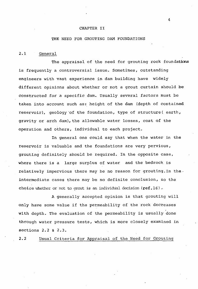
THE NEED FOR GROUTING DAM FOUNDATIONS
2.1 General
The appraisal of the need for grouting rock foundaticns
is frequently a controversial issue. Sometimes, outstanding
engineers with vast experience in dam building have widely
different opinions about whether or not a grout curtain should be
constructed for a specific dam. Usually several factors must be
taken into account such as: height of the dam (depth of contained
reservoir), geology'of the foundation, type of structure( earth,
gravity or arch dam),the allowable water losses, cost of the
operation and others, individual to each project.
In general one could say that when the water in the
reservoir is valuable and the foundations are very pervious,
grouting definitely should be required. In the opposite case,
where there is a large surplus of water and the bedrock is
relatively impervious there may be no reason for groutinq.In the.
intermediate cases there may be no definite conclusion, so the
choice $ðer or not to grout is an individual decision (ref. 16 ) ., A generally accepted opinion is that grouting will
only have some value if the permeability of the rock decreases
with depth. The evaluation of the permeability is usually done
through water pressure tests, which is more closely examined in
sections 2.2 & 2.3.
2.2 Usual Criteria for Appraisal of the Need for Grouting

2.2.1 The Water Pressure Test (or Lugeon Test)
This test consists simply in taking measurements of
the amounts of water injected into a given borehole at several
depth intervals. The Lugeon test is carried out with a standard
pressure of 10 kg/cm2 the length of each interval tested generally
being about 5m. The result is expressed in litres of water
absorved /minute/meter. This unit is usually called lugeon unit
(Ref. 2).
The following sketch (fig. 2-1 ) illustrates the
device and physical execution of the test.
It is generally accepted (Ref .2) that 1 lugeon
- 5 corresponds to a permeability of k = 1,3 x 10 cm/s. This value
was calculated from correlations established with results of water
tests in granular material.

tlexi ble pressur,e tube
f i g . 2 . 1 Arrangement o f the water pressure t e s t u s i n g a s i n - g l e packer
( After Rissler)

2.2.2 Criteria Based on the Water Pressure Test
(a) Lugeon's Criteria
These criteria state that the foundation issufficiently
impervious if the water loss does not exceed 1 litre per meter, .
under a pressure of 10 kg/cmL maintained for 10 minutes and
therefore grouting is not necessary. If the dam is lower than
30m, a water loss of 3 lugeon units could be tolerated(Ref.2).
(b) English Practice
According to Lancaster Jones (Ref. 6) acceptable
water losses have varied in England from 1 gallon to 0,14 gallon
in a 10 ft stage in 10 min at 100 psi. These values are equivalent
to 0,22 and 0,03 UL.
( c ) Rissler (11) briefly mentions in his thesis that
in the USSR a similar method is used. There, the test results are
reduced to a unit pressure.
2.3 Criticism of the Existing Criteria
Since the evaluation of the need for grouting has
been established based on results of water pressure tests, these
criteria have been subject to several criticisms. Some of the
notable criticisms are:
(a) Casagrande (Ref.3) mentions some cases of dams
where the water pressure tests indicated the need for grou'ting
and the grout curtains proved unnecessary or even useless.
(b) Nonveiller (Ref.10) argues that water pressure
tests often provide an over&imation of the permeability of the
rock, due to several factors, such as:

- leak around the packer. - hydrostatic pressures impose new stresses and cause deformation of the surrounding rock with
resulting opening of fissures, increasing the
actual permeability.
- after the construction of the dam, the seepage pattern may cause some compression of the foundation,
thus reducing its permeability.
(c) De Mello & da Cruz (Ref. 4) consider that the
type of dam should be taken into account. In this way, they argue,
the seepage under a thin arch dam would be much greater than the
seepage under a homogeneous earth dam, due to the fact that it
would have a shorter seepage path.
They further present some keen considerations about
the width of the grout curtain. They consider for example, that
for an earth dam having a base width of 275m a grout curtain 4m
wide and a permeability 1/4 of the ungrouted rock the improvement
would be equivalent to an increase in the seepage path of 20m,
what is indeed a very small improvement. In other words, they
reanmended the use of wider grout zones.
(d) Sinclair, in this PhD thesis (Ref. 17) presents
some very interesting considerations on this subject. He
appropriately states that the water pressure tests donlty%ld
reliable measurements of the groutability of the rock, since a
determined "water take" can be due either to a small number of
large fissures or to a great number of narrow fissures.

Fine fissures would allow the flow of water but wouldn't allow
grout to penetrate into them. It must be noted however that
Sinclair's study refers only to cement grouts.
Sinclair further notices that in cases of open
fractures, it is a common occmnce the pump run at full capacity
with no pressure developed. This happens when the pump does not
have a large enough capacity. Fig. 2.2 illustrates the variation
of the permeability with fracture width.
Fig.2.2 Variation of the permeability with fracture.width.
(after Sinclair)

2.4 - Suggested Criteria for Evaluating the Necessity of a Grout Certain
Some researchers have proposed changes in the
current grouting criteria, in view of the criticisms mentioned-
in section 2.3.
The contributions of De Mello(4) & da Cruz, Nonveiller
QO) , Sinclair ( 1 7 ) and Rissler (11) particularly reflect on
this subject. Their suggestions are presented below in a
summarized form.
De Mello & da Cruz (4) propose the following criteria:
(a) No treatment should be necessary for dams of the
narrowest "impervious" base widths (approx. 20% of the height
if the foundation rock yields coefficients smaller tham 0,3
lit/min/m/atm for dams under 30m; 0,2 for dams between 30 and
lOOm and 0,l for dams higher than 100m.
(b) For dams with wider impervious base width the
above limiting coefficientes may be increased in proportion to
the increase of the base width up to a maximum coefficient of
1,O lit/min/ m atm.
(c) In all cases, foundation rock with coefficients
higher than 1,O must be carefully considered with regard to
requiring both a drainage system and a sealing system. . (d) For intermediate cases either an effetive drainage
system or an effetive sealing system may be selected.
Nonveiller (10) proposes the following changes in the
water pressure test procedures:

- The percolation should be measured in any borehole stage for three different pressure levels, the
lowest pressure being not greater thah the hydros-
tatic head to the depth of the packer.
- The permeability should be computed from the
percolation corresponding to the lowest pressure
level and not from the percolation at 10 kp/cm 2
pressure, as is usually done.
Nonveiller illustrates his proposal with a table
and graphs, showing the differences in the estimated value of
permeability using the usual criteria and his criteria. The
mentioned table and graphs are presented below (Fig. 2.3).
TABLE 2.1
Checkinole nP 9 17
1- Rate of flow computed from water
pressure tests in all stages lit/ min 630 6 5
2- Detto, actually measured lit/min 43 8 , 3
3- Ratio of computed to measured flow 12 8
E s t i m a t e d x c o m p u t e d f l o w o f w a t e r u n d e r dams

P m l n r i o , ~ vr prrin,r. l i . ~ p t n ~ s . (A) lnrrainnr jlaw l t o r r r q r r ~ r a ~ v rrraarial, ( 8 ) nrrb~~lnrr,flu~v. (C) upcniu,y rmk analurc rirhdtr pnrmn (DJ <rosiot, ~9 j'z3xt<re J';fli!$,q
Fig. 2.3 ( After Nonveiller)

Nonveiller, therefore proposes the evaluation of the
need for grouting to be done using corrected values dpermeability.
Sinclair (17) proposes measures to offset the shortz
comings of the water pressure tests, consistently with his
criticisms. His suggestions are:
- use of pumps of greater capacity so as to make possible the determination of the water (or grout)
take for high permeability rocks.
.- The substitution of the water pressure tests by
grout injection tests, so as to make possible the
distinction between groutable andnon-groutable
fissures. According to Sinclair the water pressure
test would consist of two short consecutive
periods of equal length grout injection. The average
rate of grout slurry absorption for the first
period is designated as Grout Injection Index.
This parameter relates only to the groutable cracks,
unlike the water injection index. The ratio between
the rates of injection for the second and first
period is termed Ratio of Injection Rate (RIR).
Systems of narrow fractures will have - low RIR and low groutability and hversely.
It is the writer's opinion that Sinclair's work is
more directed towards an evaluation of cement groutability than
towards of the need for grouting from the point of view of
permeability. Indeed, if cement grouting is not possible there

are other grouts which could be suitable.
Rissler (11) presents in his thesis work a very
careful treatment of the subject. He proposes an experimental-
theoretical method for determining the anisotropic permeability
of fissured rock from the results of the water pressure tests, , when the spacial orientation, number of fissures and apertures
and relative roughnesses of the fissures are known. In some
circunstances a good estimate of these factors can be made as in
the case of- tunnel excavation, which permits the visual inspection
of the systems of joints.
According to Rissler's conciusions the anisotropic
permeability resulting from a system of fissures can be
calculated using the formula:
n n and n are the components of the unit vector, normal to x' Y Z
the joint planes. The meaning of the other symbols can be found
in Fig. 2,4, bellow:
Fig.2.4 Example of a joint set consisting of 5 joints c f
various apertures, roughnesses and spacings
( After ~issler 1

If several sets of joints exist the total plrmeability
of the rock mass can be determined by superimposition of the
permeability tensors of each set of joints. Rissler doesn't
propose actually grouting criteria, but an acurate method
for evaluating the convenience of it.
2.5 Considerations Regarding Safety of Dams as Related to Grouting
This issue was approached by Casagrande, in his Rankine
lecture(Ref. 3). He raised doubts about the effectiveness of
single line grout curtains for control of seepage. According
to Casagrande's opinion grouting should not solely be relied
upon for safety of the dam, a drainage system being an
obligatory component of the design.
Walker states that "the hazard associated with seepage
at dam sites has little if any relation to volume of water loss".
De Mello & da Cruz(Ref. 4) endorse Walker's statement
in their 1959 paper,but in his Rankine Lecture De Mello (Ref.
5 ) points out that "in a rock with open joints hindering
infiltration is a definite a-fortiori pre-requisite", meaning
that grouting has to be done in this case. He further stresses
that a drainage system is obligatory whereas grouting can be a
permissible complement in some cas.es.
Sabarly (Ref.10) shows that drainage systems can become
clogged and this could be a very dangerous situation. In a
hypothetical situation like this, grouting would then become
very important since it would reduce the percolation amount.
Schmidt (Ref. 14) relates the case of Hales Bar Dam,
where the fissures in limestone progressively widened under

the action of flowing water.
According to he writer's opinion, the safety of a
dam relies to a certain extent on the effectiveness of a grout
curtain in the circunstances described below:
1- When the drainage system cannot handle the total
amount of seepage which would occur without grouting (due to
inadequate proportioning,clogging of drains, increase of
permeability, etc) . 2- When the foundation rock is either erodible or
soluble.

CHAPTER I11
TYPES OF GROUTING - A GENERAL VIEW
3.1 General
From a survey of the literature several basic types-
of grouting were identified, according to the individual purpose
as listed below:
- foundation grouting - anchor grouting
- grouting for reclamation of civil engineeringworks - grouting for correction of settlements
Foundation grouting in its turn, can be subdivided
into two types, accordincj to the foundation terrain:grouting
of soils and grouting of rocks.
Grouting of fissured rock can be divided into 5
classes according to the Corps of Engineers (21) and into
2 classes, according to the usual classification ( 2 , 16,23).
3.2 The Corps of Engineering Classification
According to the Corps~classification there are 5
classes of rock foundation grouting, as described below:
- Curtain grouting: This is the drilling and grouting of one or more parallel lines of holes in a founda-
tion or along reservoir rim for the purpose of
creating a barrier of cutoff against excessive
seepage.
- Consolidation grouting is an operation performed over an areal grid pattern in plan and to a

relatively shallow depth into the foundation, for
the purpose of "consolidating" a mass of highly
fractured or otherwise defective rock.
- Contact grouting is the injection of a grout slurry at the contact of a structure with a vertical or
nearly vertical rock surface for the purpose of
sealing any water passages that may exist due to
skinkage . - "Dental Treatment" is the operation of cleaning a rough surface and filling with mortar, grout or
concrete. Localized pockets of weathered rock,
potholes, faults or other foundation flaws that
extend below the general foundation surface.
- "Slush Grouting" is the filling of surface irregularities and open fractures in a rock founda-
tion with a sanded grout or mortar on which earth
fill is to be placed.
3 . 3 The"Usual"Classification
According to the more common dam designer's
terminology there are two basic types of rock foundation grouting,
ie. curtain grouting and consolidation grouting. The other 3
types mentioned by the Corps' classification are considered
complementary civil engineering works.
In this report only curtain grouting will be dealt
with.

CHAPTER IV
GROUTING METHODS
4.1 General
As an introduction to this chapter we shall first
of all define clearly the distinction between grouting methods, , grouting procedures and grouting design. Grouting design is
defined as determination in advance of construction of:
- geometrical characteristics of the grout curtain such as depth of the grout holes, configuration of the curtain,
number of lines, inclination of the holes, spacing between holes,
initial guides on grout mixes, pressures and when to grout.
Grouting procedures are defined as general field
measures, which can be changed according to the conveniences and
requirement by the Field Engineer, or by the Inspector. The
procedures refer to drilling operations, choice of grouting
pressure and grout mixes during the conduction of the works
Grouting methods are defined as one of the two
standardized ways of conducting the grouting operations for a
determined job, i.e. stage grouting and packer grouting.
In stage grouting the hole is drilled and grouted
in stages of depth from the top, with the grout being inserted
through a pipe nipple which is fixdd into the rock at the top
of the hole. The hole is usually drilled in two or more
increments of depth. After the first stage hole is grouted
completely, the hole is redrilled and extended down to the
second stage. The new, greater lenght of hole is now grouted

under a higher pressure. If a 3rd stage is used, the process is
repeated.
Cambefort (2) recomends the lenght of each
stage not to exceed 10m. Sometimes, stage grouting has been
employed for full depth treatments of considerable lenghts.
However, as Cambefort stresses this is not advisable because
of the likelyhood of sedimentation in such a long columms.
In packer grouting the holes are drilled at once
to the full proposed depth. Subsequentely a "packer" which is
a mechanical device for sealing off the hole at any elevation
is inserted and sealed against the walls of the hole. After
the packer is in place grout is injected. Grouting of the hole
is completed by gradually raising the packer in sucessive stages
and grouting at successively lower pressures. If a double
packer is used, grouting could be done either from the bottom
of the hole up, or from the top down.
The figures below illustrate the physical execution
of the mentioned methods.

Return Llne
Pressure
Pvnnel R
. .
f - t lr l l l Hole
Fig. 4.1
Typical arrangement of a packer grouting installation (After Sinclair)
Fig. 4.2'
Stage grouting
(After Sabarly)

required and less pipe connections are needed.
2- Packer grouting allows the use of high pressures
without the attendant risk of surface breakouts.
3- Packer groutingWon the way down" enables very
localized treatment of any seam encountered
during drilling. This is accomplished by setting
the packer just above the "leaky" zone and
injecting with the desired mix. Double packer
grouting can also be used to treat "leaky" zones
even if the entire hole is open. Stage grouting
is less versatile in these respects.
Sometimes in extremely fractured rock it is not
possible to use packer grouting, since the grout can find its
way upward, and the packer can be become grouted in the hole.

CHAPTER V
TYPES OF GROUT
5.1 General
A survey of the literature on grouting revealed
that the bibliography on this important subject is extensive.
Indeed there are works by Cambefort (2), Task Comitees of
Cement Grouting (19) and Chemical Grouting (20 ) and tens of
other references. However, it is the writer's opinion that
the only one who approaches the problem of curtain grouting in
bedrock in a systematized and comprehensive way is Cambefort (2).
Therefore, this chapter will be a brief summary of Cambefort's
work on types of grout. Cambefort divides grouts in 3 basic types:
(a) Cement grouts
(b) Chemical grouts
(c) Asphalt grouts
Cement grouts can be further subdivided into stable
and unstable grouts.
There is still a fourth type, which he calls aera-
ted grout. It consists of an air emulsion of any one of the
other 3 types.
In the following sections each one of the afore
mentioned types are discussed and also the criteria that should
be used for the choice of a particular grout type.
5.2 Relevant Properties of Grouts
The more relevant properties of mortars of
injection are, namely:

- viscosity - consistency, including thixotropy and rigidity - particle sizes - bleeding or segregation
- setting time These properties can be measured by specific tests
whose description is beyond the sropeof +his work.
There is no such thing as standard properties for
grouts. Indeed,the requirements which have to be satisfied by a
grout vary widely with the characteristics of the foundation to
be treated and with its purpose.
The destinction between stable and unstable grouts
is made on the basis of the "bleeding" properties of the grouts
as it will be seen in sections 5 . 3 & 5 . 4 .
5 . 3 Cement Grouts
5.3.1 Unstable Grouts
The prototype of the unstable grout is the common
cement - water mortar, provided the mortar is dissolved enough. It is "unstable" because the cement grains are large, so as to
display appreciable sedimentation before setting of the cement.
Other kinds of unstable grouts are the mixtures
of water, cement and a filler, such as sand, sawdust, flour,etc.
The properties of the grout may vary widely according to the
choice of the filler.
In a general way, unstable mortars have more
than enough strength to withstand the stresses originated from

the water pressure.
5.3.2 Stable Grouts
Stable grouts are suspensions in water of grains
small enough so as not to display any bleeding or sedimentation
during the injection. The simple addition of a colloidal clay
to an unstable mortar renders it stable, since the colloidal
particles prevent the sedimentation of the larger ones.
Cambefort (2) divides the stable grouts into
three main classes: suspensions of cement with high final
strenght clay suspensions and suspensions of sand-clay-cement.
Each of these classes comprehends several grouts, as listed
below:
(a) Suspensions of cement with high final
strength
- cement bentonite - cement sodium silicate - activated cement mortars - cemenc - ashes - cement - rock flour - cement - sawdust (b) Clay suspensions
- treated clay - clay - oil - clay gels (c) Suspensions of clay-sand-cement

- clay - cement - clay - cement - sand Each one of the above mentioned grouts has its
peculiar composition and characteristics. Sometimes the difference
between two of them is just a matter of grain size distribution
of the clay, or of a particular admixture.
It would be pointless to describe here all the
above grouts and their properties (See Ref. 2 for detailed
description).
In section 5.7 there are descriptions of the use
of a few grouts, with provide an illustration of what can be
achieved by the choice of an appropriate mortar.
5.4 Chemical Grouts
Cambefort (2) distinguishes basically between
3 classes of chemical grouts:
- hard gels sodium silicate and lignochromiun - plastic gels of sodium silicate and deffloculated bentonite
- organic resins Chemical grouts are generally liquids with about
the same viscosity as water, and therefore with great capability
for penetrating fine granulated soil and fine fissures in rock. .
Some of these grouts set with the consecutive injection of the
grout and the reactive and others set over a requisite time
period.
The use of chemicals in injection of fissured

rock is not common mainly because of their high cost and also
because the common cement grouts are generaly satisfactory for
most jobs. Indeed, in a survey of the literature the writer
could not find any case of rock impermeabilization with chemical
grouts.
5.5 Asphalt Grouts
These grouts according to Cambefort's opinion
would be the ideal injection mortars if they were cheaper and
easier to place in the construction site.
There are basically two types of asphalt-grouts:
- Solid asphalt which must be heated in order to be injected.
- Asphalt emulsions, which can'be injected without heating. The rupture of the emulsion is brought
about by the addition of a specific chemical.
There are at least two patented asphalt grouting
procedures: Shellperm and Soletanche (2).
In order to decrease the cost of these grouts,in
some circunstances a filler such as sand, or any other granular
material can be added.
5.6 Aerated Grouts
These consist of any one of the aforementioned
grouts with emulsionated gas, in such a fashion as to form a
foam. In some circunstances this expedient can afford
substantial savings due to a smaller grout consumption. This
solution is particularly interesting for injection of cement

grouts, since it improves some properties ofthis mortar. For
instance, the bleeding decreases,the rigidity increases and the
penetrability increases remarkably.
These grouts can be prepared by the addition of a
specific chemical. For example, alumininium powder added to
cement grout gives origin to hydrogen bubbles.
5 . 7 The Choice of an Appropriate Grout
for a Specific Case
In the process of choosing an appropriate grout
for a given job several factors have to be taken into account:
- properties of the grout, such as viscosity, thixotropy, setting time.
- relative price of the grouts - this a very important factor indeed. Cambefort presents a
comparative table of prices for French
conditions, as reproduced below:
TABLE 5 . 1 Comparative prices of grouts
Grout Relative price
Water cement suspensions
Clay - cement Joosten Gel
Hard gels Soletanche 6 . 3
Gels of Lignochromium 6 . 5
Plastic gels silicate-aluminate 2
Deffloculated bentonite
Deffloculated clay
Clay - oil 20
AM 9 50

Grout Relative Price
Resorcin - formQl Asphalt - silicate emulsions Asphalt - resorcin emulsions
- Nature and conditions of the rock foundations
- Depth and equilibrium state of the grounelwater The nature of the problem doesn't allow the
establishment of definite rules, but there are some general
guides which can be regarded as good first indications as
summarized below:
- for finely fissured rocks, the common cement grout is the treatment to start with. Grout consistencies start
with 1/10 cement/water relation in volume and thicken
progressively up to 1/4 or even 1/2.
- The grouting of fissures in porous rocks is .
difficult since the porous walls of the fissures absorb water
from the grout, rendering it ungroutable. Is is necessary to
inject a sodjum silicate gel before injecting cement grout.
The sodium silicate gel obturates the pores of the porous
rock, allowing for a later common cement - grout injection. - Open fissures can be treated with a clay -
cement grout, since there will be considerable cement savings.
Sometimes it is convenient to use grouts with short setting

time, so as to reduce the grout losses. Another expedient is
the addition of sawdust to the grout, in such a way as to
rapidly increase its viscosity, so preventing the grout from
travelling long distances away from the injection hole. The
figures below illustrate these concepts:
LOW V1SCOStTY f=l VERY VLSCOUS GROUT
Fig.5.1 -Injection of a mixture grout-sawdust
When the fissures are important zones of water
flow as is often the case in limestone terrain, common grouts
would be washed away. The solution in this case would be to
construct an inverted filter in the cavity and after the filter
is in place to inject hot asphalt wich would coagulate immediately
in contact with the water. The fig. 5.2 below, illustrates these
procedures:
Fig.5.2 - suggestion for grouting of fissures in limestone

32
When there are both wide fissures and fine
fissures the large cavities would be obturated first using proper
grouts and the fine fissures would have to be grouted using a
more diluted grout.
Finally, we should remind that the injection of
fine fissures with hot asphalt could yield good initial results
but it would not be a final solution, since the water pressure
would slowly expel the asphalt from the cracks- An asphalt
injection combined with a cement grouting would be a lasting
solution.

CHAPTER VI
GROUTING PROCEDURES
6.1 General
As mentioned in section 4.1 Grouting Procedures
refer to drilling operations, choice of grouting pressure and
grout mixes during the conduction of the works.
There are two main grouting practices: the
European (or French) Practice and the North American Practice.
The methods and design of grouting are not too different between
them, but the Procedures are widely different. Several-authors
have already discussed the conflicting features of this subject,
but there is no definitive conclusion so far. Therefore, we will
briefly present both practices and the applicable criticisms.
6.2 Drillinq
Drilling can be done either by percussion or
rotary techniques. There is a controversy about the advantages
and disavantages of each method, as summarized below:
(a) Advantages of percussion drilling-lowercost
(b) Disavantages of percussions holes - greater possibility of clogging of the entrance of the fissures by the
drill cuttings - deviations. - Roughness of the walls of the hole.
(c) Rotary drilling doens't have such disavantages
but is has a muchhigher price per meter.
It must be stressed that if packer grouting is to
be used, rotary drilling is preferable, since it provides a

3 4
better seating for the packers.
It is a generally agreed opinion that the
diameter of the borehole is irrelevant. In most cases the diameter
of the hole does not have any influence on groutability or
"grout take" and therefore the smaller the diameter, the greater
the cost savings. In North American terminology there are 3
standard sizes of holes:
EX (0 = 1 1/2"); AX (0 = 1. 7/8") and BX ($I = 2 3/8").
6.3 Grouting Pressure
This is definitely the most controversial issue
between the European and North American Practices.
- Both practices accord that grouting of upper layers of the bedrock should be conducted at
lower pressures, and
- the grouting pressures should be a function of the weight of the overlyng rock.
Regarding other factors, there are considerable
disagreements, as will be discussed in the sections following:
(a) North American Practice
The traditional North American Practice is to
recommend injection pressures not to exceed 1 psi/ft of depth.
These pressures would be such as to insure against uplift on
the basis of the weight of the overburden, neglecting the
uplift resistence of the rock mass. This criterion is recognized
as conservative, however, and is reserved only for weak rock,
horizontally jointed rocks or to the upper layers of the foundation.

In 1962 the "Task Comitee for Cement Grouting" (19)
presented a suggested graph for alowable grouting pressures
as a function of the rock type. Substantially higher pressures
are recommended in this work. This graph is presented in
fig. 6.1
North American Engineers generally object to the
@xwxence of either uplift or fracturing caused by grouting.
They argue that hydraulic fracturing would open new fractures
which coul& be dangerous and that if these fractures were
filled with grout this would be a waste of grout. The pressure
which could give rise to hydraulic fracturing was computed by
Morgenstern & Vaugham (8). This subject will be treated more
closely in section 7.
An important factor that must be considered in this
discussion is that the penetrability of the grout depends on
the relative dimensions of the cement grains and the fissure
apertures; in North America, generally finely ground cement is
used and therefore the necessary pressure needed for achieving
a certain penetration of the grout is lower than in Europe,
where coarser cements are used.
Some North American researchers found that the
shear strenghts of a newly grouted Lock is less than that of a
intact rock. It is the writer's opinion that the loss of
strenght is irrelevant in most practical cases, since the
strenght of fractured rock is good enough from the point of view
of bearing capacity.
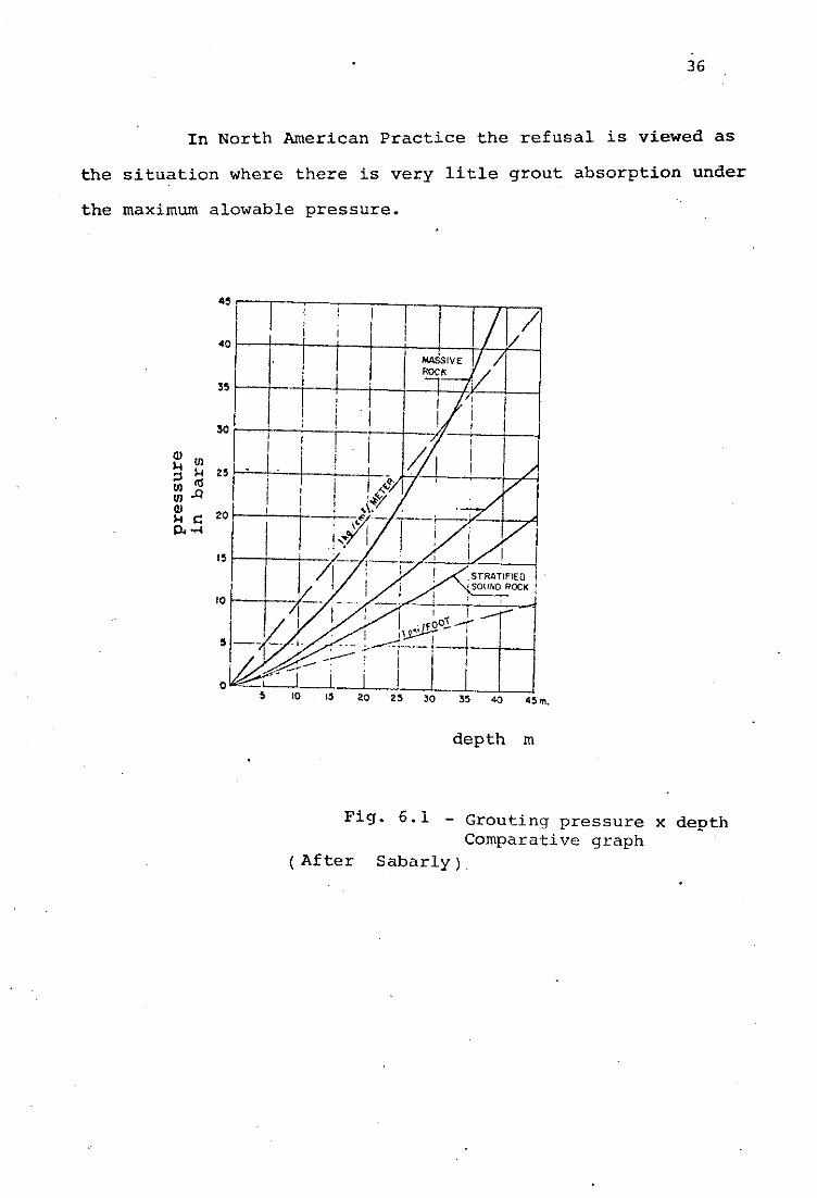
In North American Practice the refusal is viewed as
the situation where there is very litle grout absorption under
the maximum alowable pressure.
depth in
Fig. 6.1 - Grouting pressure x depth Comparative graph
( After Sabarly )

(b) European Practice
Traditional European Practice recommends the use of
pressures up to 5 psi/ft of depth. Cambefort ( 2 ) in his
comprehensive book on grouting argues that the only way to
grout certain fissures is through the use of high pressures, in
such a fashion as to provoke the elastic deformations of the
rock mass, with the consequent increase of the opening of the
fissure. When the application of the pressure ceases, the grout
is compressed by the rock, forming a watertight joint, as
sketched below:
'REAM -
F l N A t OF CEMENT DEPOSITION -
Fig- 6.2 - Formation of a joint under high grouting pressure
(Alter Cambefort)

- Cambefort further states that in some instances the
hydraulic fracturing of the rock mass could be even desirable.
Indeed, when the state of stress in the rock mass is such as
to allow the formation of vertical cracks, one can take advan-
tage of this situation and try to form a continuous vertical
grout curtain. However, this a very particular situation. In
the more general cases, Cambefort regards cracking as
undesirable but unavoidable since use of lower pressures would
conduct to unsatisfactory grouting. He views the phenomenon
of cracking as not being so dangerous as depicted by the N.A.
engineers.
Cambefort's views are generally supported by other
European authors, like Sabarly (lo), Nonveiller (lo),
Zaruba (25) and others.
In European Practice the refusal is understood as the
situation where the grout take is very small under a pressure
a little higher than the pressure needed to grout, ie, to open
the existing fissures and not as to give rise to uplift. One
could think that this concept would lead to exaggerated grout
takes, but this is not so because the viscosity and grouta-
bility of the mortar can be controlled so as not to allow
waste.
6.4 Grout Mixes
In chapter 5 the problem of choice of the grout has
been approached and the great number of available grouts has
been mentioned. In this chapter some brief comments on the -
usual procedures of cement grouting will be made. It is beyond
the scope of this report to go into details on such an
extensive subject.

(a) North American Practice
The tradicional North American (Corps of Engineers)
Practice of cement grouting is to use a maximum water/cement
ratio of 3 or 4 and a ratio of 1:l is the most common.
Sometimes the use of fillers or admixtures is considered
depending on the conditions of the foundation to be injected.
The grout consistenceis are not changed very often during a job
in the N.A. practice.
In a survey of the North American literature the
writer failed to find any recommendation about the grout
consistency as a function of the water pressure test results.
(b) European Practice
Cambefort and Zaruba present some very interesting
observations based on their experience in Europe.
Zaruba (25) suggests that grouting of closed joints
should be done with a thin mixture (W/C = 8/1) and for larger
cracks near the drill hole a thicker mixture (W/C=4/1 to 1/11
is used. Wide cracks should be filled with a thick mixture
(1:4 eg) at the beginning and completed with a thin mixture
( l r 8 to 1:lO). Zaruba (2) suggests that when cracks are
narrower than 0,2 mm clay or chemical grouts should be used.
As already discussed this is not Cambefort's opinion.
Cambefort (2) suggests that a approximate relation-
ship between the results of lugeon tests and grout mixtures can
be established for a given refusal pressure of 50 kg/cm 2
(very high pressure). This relationship is summarized in the

t a b l e below, f o r uns tab le grouts .
TABLE 6 . 1 Suggestions f o r g rou t mixes
Water absorpt ion
lugeon u n i t s
Grout mix C/W a t t h e beginning of t h e In- F i n a l Grout j e c t i o n Mix
1/8
1/8 1 / 4
1 / 4
1/2 o r stable mrtar
These are only rough guides , of course.

CHAPTER VII
THEORETICAL AND EXPERIMENTAL STUDIES
ON GROUTING
7.1 General
As an introduction it can be said that grouting
, presents problems practically impossible to tackle analytically.
Indeed, the heterogeneity of rock foundations is such as to
render useless any mathematical or physical model. The degree
of accuracy in any feature of grouting design is quite distant
from that usually achieved in Civil Engineering in the sense
that in most fields of civil, it is possible to predict the
results of a determined design procedure with a certain
re liability. In grouting the reliability of these predictions is
doubtful at best. In some situations the efficiency of the treat-
ment is zero, in others it is satisfactory. Nevertheless there
are some specific points in this subject where important
qualitative conclusions can be drawn from simplified models.
These particular points will be briefly reviewed in section 7.2.
7.2 Theoretical Approach to Groutinq
The few points in this subject which are amenable to
any theoretical treatment are:
(a) Injection of a newtonian fluid into a fissure
- An equation relating pressure, quantity of flow and
depth of penetration of grout into a horizontal single fissure
has been derived by W.J. Baker ( 2 ) .

where:
$ = viscosity coefficient
e = width of the fissure
Q = quantity of flow at a determined point
R = distance from the grout hole
r = radius of the grout hole 0
Hypotheticnl dlstr?butlon - of pressure head along Y fracture
0 Radius. r R
Fig. 7.1 - Injection of a fissure (After Sinclair )
Fig. 7.2 - Distribution of pressure along the fissure
(After Sinclair)
From the equation above, the pressure at the beginning
of the injection is strongly dependent on the quantity of grout
injected for a given fissure and a given grout mix.
(b) Influence of pressure on the opening of fissures
Cambefort and Sabarly studied the effect of pressure
on the opening of a single fissure ( 2 ) . Cambefort derived the
simplified formula below:
1 2
2 F m = 1.5 p r 1 - (-) w = - fr rE E
where :

W = deformation or opening of the fissure
p = average pressure
r = radius of action of the pressure to be considered
E = elasticity modulus
Sabarly( 13 ) derived a similar formula, as below.
Fig. 7.3 - Fissure grouting
After Sabarly
(c) Determination of the allowable grouting pressures
Morgenstern and Vaughan (1963) (9) developed a
theoretical criterion for the determination of the allowable
grouting pressures, so at not to instigate hydraulic fracturing.
They derived the formulas below: I
for K c 1
- - (dh - d w hw) (l+K) - (fh -S/w hw) (1-K) +cfcot 0' Pe 2 2 sin a for K z 1
- - ('dh - d w hw) ( 1 + k) - (xh-l(w hw) (1-K) *'cot 0' Pe 2 2 sin 8 '
where
jl = angle of shearing resistance
c' = cohesion intercept
= ' bulk density of the material above t@ level under consideration

h = heigth of the material above the level under
consideration
hw = piezometer level of the groundwater above the
level under consideration
'e = allowable pressure
This study finds its best application in the case of
injection in soils and in porous or weak rocks.
(a) From a comparative point of view Cambefort (2)
and Sabarly (13) studied the relationship between the number and
width of fissures with the permeability. This study is illustrated
in Fig. 2.2.
(e) From a macroscopic point of view, Sinclair (17)
determined some equations relating the'results of water pressure
tests with "grout take". This subject is studied more closely in
Chapter 8, Section 8.4.
( f f Again from the macroscopic point of view Nonveiller
QO) presents curves relating amount of "grout take" and permeability
with hole spacing. However he does not mention the range of
application of these curves, since they are based on statistical
studies (see Fig. 8.12).
7.3 Experiments on Grouting
7.3.1 Laboratory Experiments
The writer could find only 2 references with respect
to laboratory experiments on grouting, in his survey of the
literature.

The earlier experiments were conducted by Bernatzik
(2 1 and refer simply to the problem of grout circulation inside
the boreholes. He carried out experiments injecting grout into
porous pipes with impermeable spots and studied the configuration
of the cement deposits inside the core.
The illustrations below reproduce some of his
findings:
Fig. 7.4
Equipotentials and flowlines in a
borehole during injection
(After Cambefort)
The later experiments were performed by the US. Corps
of Engineers in Vicksburg (23). They consisted of grouting tests :
in an artificial opening in such a way as to induce planar flow
of the grout. The sketch below illustrates the device used for
the tests.

Device used by the U.S. Corps of Engineers for grouting tests
I
PUMP - - - PRESSURE LINE - -
The test results were not satisfactory as it was
never possible to completely fill the fissures due to bleeding
of the grout. Therefore, there was never bonding between the
grout and the upper wall of the fissure.
Cambefort(2) comments on these experiments, consi-
dering that probably the unsatisfactory results of the experiments
were due to failure in reproducing the field conditions, ie,
using too rigid a device. Besides, the tests results were
conducted in a planar flow fashion, which is not the actual
grout flow pattern.
7.3.2 Field Experiments
Field experiments consist usually in full scale or
sometimes small scale tests with possibly extraction of cores.
Cambefort relates 4 cases of such field experiments. In some
circunstances excavation of tunnels has been done in order to
observe the results of the injection works.

Benko relates in detail the way a large scale
grouting test was performed at Portage Montain Dam site in B.C.
(see section 10.4. ) .

CHAPTER VIII
GROUTING DESIGN
8.1 General
As discussed in Section 4.1 Grouting Design is under-
stood as the determination of the geometrical characteristics
of the grout curtain, the establishment of initial guides on the
procedures, methods of grouting and when to grout. An approximate
prediction of the grout takes would also be desirable £or tender
documents.
As some items in this chapter have already been
treated in early chapters, we will only refer to the respective
section, if no further considerations are judged necessary.
8.2 Required Input Data for Groutinq Design
The input data usually necessary for designing a grout
curtain are:
(a) Detailed geological survey of the damsite,including
information about types of rock, ground water, faults, fissures,
foldings . (b) Permeability of the bedrock. These data are
generally determined from water pressure tests (or lugeon tests)
as described in section 2.2.
( c ) Overall design of the dam.
(d) Availability and cost of grouts and grouting
equipment.
(e) Availability and cost of drilling.
(f) Information about the state of the stress in
the bedrock.

(g) A study of similar case histories.
Information about a, b and c are usually available
prior to the bid; d and e would have to be estimated by comparison
with other jobs. Information f has not been usually available
but more recently the trend is to attempt to determine the state
of stress of the bedrock in situ.
It shoud be added that it would be desirable to carry
out some additional tests, as listed below, prior to the
beginning of the grouting operations.
- laboratory tests on all the suitable constituents - grouting tests at the dam site, for determining allowable pressure, grout hole spacing, grout mix
to be used effect of admixtures, setting time of the
grout and estimation of the total "grout takes".
- drilling tests, to determinate the suitability of a determined drilling method and diameter of hole.
- grouting tests as proposed by Sinclair (see section 2.4) would provide useful information on the cement
groutability of the rocks mass.
8.3 Geometrical Chracteristics of the Grout Curtain
The geometrical characteristics of the grout curtain
which would have to ne predicted are' namely:
(a) Plan view arrangement of the grout holes
(b) Depth of the grout holes
(c) Number of grout lines
(d) Inclination of the grout holes

(e) Grout hole spacing
(f Drilling diameter
These features will be discussed separataly below:
(a) The grout holes should be located in such a way
as to constitute a continuous watertight barrier together with
the dam or together with the upstream impervious membrane, as
sketched below.
Fig. 8.1 Position of the Grout Curtain (After Wahlstrom)
Fig.8.2 Plan View of the Grout
*<; ...... Curtain -.. o . 0 0
(After Wahlstrom) '. '. - - . . . .'. .........
iL
CURTAM GROUT HOLES ,, FROM GRCUT ULP
.,I ,' -..-.._-_ -_____________.----J
.. Fig.8.3 - Grout curtain under dams with upstream
r . . . membranes
When the dam is a homogeneous earth embankment or a
concrete gravity one, the grout curtain should be located close
to the heel of the embankment, in such a way as to leave enough
space downstream for the relief wells.

UPSTREAM
Fig . 8.4
P o s i t i o n of t h e -
under a concre te
g r a v i t y dam .~ - - . - .
ZONE OF CONTACT ( A t t e r Sabar ly ) GROUTING
When it is a t h i n a r c h dam, t h e deformation of t h e
s t r u c t u r e must be t aken i n t o account. Indeed, by t h e t i m e o f t h e
f i r s t f i l l i n g t e n s i o n c r a c k s may occur a t t h e h e e l of t h e dam,
is such a way a s t o r ender t h e g r o u t c u r t a i n u s e l e s s . Sabar ly
(13) proposes a des ign t o o f f s e t t h i s problem.
MRECTLY WITH
Fig. 8.6
F ig . 8.5 Design prsposed by Sabar iy
Cracks under an a rch dam (Af te r Sabar ly )

(b) The depth of the grout curtain is controlled by
the geological conditions at the dam site. A usually utilized
criterion is to grout to a depth where the permeability is 1-2
lugeon units.
Wahlstron ( 2 4 ) suggests that in the absence of
geological controls, the formula D = (h/3 + 50) ft could be used (D = Depth; H = height of the dam).
In cases where the permeability does not decrease
with depth, the grout curtain is likely to be useless.
When there is a decrease in permeability characterized
by the occurrence of distinct strata, the grout holes should
penetrate into the impervious layers at least 5m. See fig. 8,7
below for illustration.
DAM CREST.
Suggested configuration Fig. 8.7
for grout holes when
(After Wahlstrom) distinct strata occur
(c) The determination of the number of grout lines
required is a somewhat nebulous matter, depending or which
design rules are regarded. The Corps of Engineers recommends'
that when the dam is lower than 66m a single line grout curtain
is isually satisfactory. Otherwise, 'multiple line grouting
shoud be used.
Casagrande ( 3 ) in his Rankine lecture, raises doubts
about the efficiency of single line grout curtains; Sherard at
a1 (16)state that no rules can be given for the circunstances

under which it is desirable to use more than one grout line;
Swiger (18) strongly recommends the use of multiple line grout
curtains, based on the argument that probably grout cannot be
forced into the smaller cracks and joints until be the larger
openings are grouted and that if cutoff is narrow, even small
openings may pass considerable amouts of water.
Downstream- - - = - - - - - - . - - - - - - - = ---C----C-
1 5 2 6 1 5 2 6 1 5 2 6 1 5 2 6
Sg.8.8Plan-multirovr grouted cutoff. Holes drilled and grouted in sequence as indicated by numbering. 96 Holes may be inclined from Gertical as required to intersect joints systems most effectively.
(After Swiger)
De Mello(4) stresses the importance of the width
of the grouted zone, and therefore in an oblique way he favors
multiple line grouting.
From a scan of the literature the writer concluded
that multiple line grouting is particularly desirable when
open fissures are being injected. The procedure of first grouting
the outer rows and subsequently the inner ones provides a barrier
preventing the grout from travelling long distances away from the
grout hole, thus reducing the waste of grout. At Portage nxoutain
dam (1) these considerations were used regarding grouting of
horizontally bedded weak shales and sandstones. The results are
reported to be very satisfactory (see section 10.4). In the case
of massive rock, however, no indication was found opposing single
line grouting.

(d) The inclination of the grout holes, according to
most grouting experts is not critical (Ref 2,13,19,20). The
Corps of Engineers mentions the desirability of the grout holes
to intercept perpendicularly the principal joints in the rock.
Sherard et aL.&@point out that depending on the nature of the
rock, inclined grout curtains could be desirable, since the same
length of grout curtains will cross more of the potential
leakage cracks than in the case of a vertical curtain. The sketch
below illustrates this hypothesis.
Fig.8.9
Inclined Grout Curtain
(After Wahlstrcnn)
When the permeability decreases markedly with depth
grout holes could be drilled in a fan - wise fashion, assketched below:
Pan - Wise p u t
curtain Fig.8.10
(After
Wahlstrom)
--

This, however, is irrelevant for wide valleys.
(e) In the determination of grout hole spacing one
has to take into accomttwo conflicting situations:
- the more fissured the rock mass, the further apart can be the holes, because large and numerous fissures
allow the grout to flow more easily.
- on the other hand, the further apart the holes, the greater theamount of grout that has to be injected to achieve
a continuous curtain.
Therefore, a compromise of the prices of drilling
and grout has to be sought. If we further take into account the
influence of the grouting pressure and consistency the problem
becomes even more complicated. One can say that there is no
single theoretical solution for this problem. What is usually
done is to conduct field tests for determining the optimum borehole
spacing, or to use the experience acquired in other jobs.
When the grout curtain consists of only a single
row, the testis performed by grouting 2 adjacent boreholes,
and to grout a control hole in between. According to theresults
of the grouting of the control borehole, it can be deduced
whether the spacing has to be increased or decreased.
In the case of a double row grout curtain the
test consists of grouting 3 holes in a triangular configuration,
and after that, grouting a 4th hole in the center. For 3 or more
rows similar tests would have to be conducted.

56
The spacing between rows is determined in the
same fashion.
A good example of the determination of the grout
hole spacing is the case of Portage Moutain Dam, where a 5 row
grout curtain was constructed.
In several cases, however, the spacing is chosen
on the basis of past experience, drilling is then done with a
much greater spacing and if found necessary, the spacing is
reduced using sucessively the split- spacing technique, ie,
grouting a secondary hole in between each two primary holes
until the grout take in the higher order holes display a
remarkable decrease.
This technique (ie, split - spacing) is presented in Fig. 8.11 below):
Fig. 8.11
Split-Spacing Technnique
(After Sinclair) Fraccure ?et 3
P S P
P - Erirrrrp Cole
P - ,Fecondarv Hole
T - ~ertiacy Pole

Nonveiller (10) presents a relationship between
"grout take" and permeability, versus spacing for an average
rock, as below:
- f .
Fig. 8.12 - 5 2
(After
Nonveiller
Relationship between grout take and hole spacing
according to Nonveiller
According to the Corps of Engineers (21) the final
spacing may be as close as 10 or even 5 ft. However, it is the
writer's opinion that this is a consequence of the low pressures
used by the Corps. Most authors (1,2,4,20,7,9,14) generally
discuss final spacings of the order of 4 - 5 m. Sinclair (17) presents some useful conclusions
on this subject. He proposes the determination of a so-called
point of productive interference. Thisis illustrated in the
graph below:
Fig.8.13 Y .=
(After Sinclair) d u 2
t Grout take x v
Hole Spacing
ue Primary Grouting-
Point of Product ive Interference
Point OF Dininlshing Returns

Once the point of productive interference is
reached one or two split spacings will be enough for the closure
of the grout curtain.
(f) Drill hole diameter
As mentioned in section 6.2 the drill hole diameter
is usually irrelevant and so the smallest suitable diameter is
usually chosen. However, in some cases of deep holes in a
sucession of soft-hard inclined layers of deposits deviation
of the drill may occur and in this case extra grouting might be
required. Therefore, one'has to be aware of this case, since
small diameter drill bits are more susceptible to deviations.
8.4 Guides on Grouting Pressures, Grout Mixes and
Method to be Followed
Regarding grouting pressures, there is really
nothing to be added to what has been said in section 6.3, except
that the control of foundation displacement should be done
during the conduction of the job.
Regarding choice of grout mixes, the only

t h i n g t o b e added t o s e c t i o n 6.4 is t h a t l a b and f i e l d g r o u t i n g
tests should b e conducted f o r c o r r e c t p l ann ing of t h e g r o u t i n g
o p e r a t i o n s .
A s t o which method i s u t i l i z e d , whenever p o s s i b l e
packer g r o u t i n g should b e used. However, t h e p o s s i b i l i t y of
u s i n g packers o n l y can b e a s s e s s e d a f t e r f i e l d t e s t s .
8.5 Es t ima t ion o f Grout Take
The p r e d i c t i o n o f g r o u t t a k e a s a f u n c t i o n o f
t e s t s p r e v i o u s l y conducted 'has been a t tempted f o r a long t i m e
by some r e s e a r c h e r s , such a s D e Mello & da Cruz, CarnbefortJJonveiller,
Molina and more r e c e n t l y , S i n c l a i r .
D e Mello & da Cruz s u g g e s t t h a t p l o t s as shown
below can b e used f o r e v a l u a t i o n o f g r o u t t a k e a s a f u n c t i o n of
wate r p r e s s u r e t e s t r e s u l t s .
Fig. 8.14
Suggested I@lationship Between Water Take and Qrout Take
cocrrtc lr+n 01 1 ~ 1 1 1 LOSS
NUMBER OF SACKS GROUTED PER HOLE A N D PER CUBIC V L COEFf lClENT O F WATER-LOSS
METER OF ROCK
Cambefort ( 2 ) s t a t e s t h a t t h e r e i s no g e n e r a l
r e l a t i o n s h i p between w a t e r t a k e s and g r o u t a b s o r p t i o n , b u t
t h e r e a r e o n l y g e n e r a l t r e n d s , and t h e p o s s i b i l i t y o f e s t a b l i s h i n g
c o r r e l a t i o n s f o r some sites. Cambefor t ' s o p i n i o n i s endorsed
by Benko's views on the results of grouting a t Portage mutain Dam.

Nonveiller (10) presents a statistical treatment
of the relationship between hole spacing and grout takes, as
mentioned in section 8.3.
Molina (8) suggested grouting test in isolated
test holes as a method of determining cement consumption in grout
curtains consisting of two lines. He studied the relationship
between the final hole spacing S, a reduction coefficient, r,
defined as the ratio of the grout take for the curtain. In
short he proposes estimating the potential grout absorption
by observing the grout take in tests, and applying the appropriate
reduction coefficient to calculate the average grout take.
The most compreensive approach to this subject
however is that by Sinclair (173 (1972) . Based on a very thorough study and M sharp observations, he proposes for a single line grout
curtain the following equations:
log GT/P = 0,66 + 0,63 log RWT/P where
GT = grout take
P = injection pressure
RWT = rate of water take
He further proposes the estimation of grout takes
using grout tests results. The following equation was found.
log GT/p = 0,87 log RGI'/P + 0 , l l ~ + 0,02 TPT
Where
GT = grout take

P = injection pressure
RGT= rate of grout take
RTR= rate of injection rate as defined in
section 2.3
TPT= test period time

CHAPTER IX
APPRAISAL OF THE EFFECTIVENESS
OF A GROUT CURTAIN
9.1 General
This subject has been approached by several
authors such as De Mello & da Cruz (1959), Casagrande (1961),
Lancaster-Jones, Nonveiller and Cambefort.
Modern authors including all the above
mentioned agree that the success of a grouting operation
should not be evaluated in terms of the amount of grout
consumption, although most of the recent papers on the subject
still refer to very large grout takes in a cheerful manner.
This stand, however, has been recognized as.nonpertinent, as
the only available indications of effectiveness of a grout
curtain are those ones based on observation of an actual
decrease of permeability of the rock foundation. In section 9.2
the more common methods for such an assessment are briefly
described.
Some authors, like Lancaster - Jones ( 6 ) for
example, pay attention on the seepage reduction due to a
hypothetical reduction of the permeability. In some ways, it is
a good manner of showing what can be achieved with grouting.
The table below illustrates his computations:
TABLE 9.1 - Effect of Reduced Permeability in Curtain

Thickness Ratio k2/kl % reduction in flow
m at contact
5 0 11 38
De Mello & Da Cruz take the same approach,
stressing on the importance of the width of the grout curtain.
Benko presents some considerations about
ways of checking the effectiveness of grouting at Portage
Moutain Dam. He describes the situation of recovered cores
as a proof of the effectiveness of grouting. It should be
pointed out that according to the terminology used in this
work, this is a proof of a grouting job well conducted, but
it is not a proof of the effectiveness of the grout curtain.
9.2 Methods for Evaluation of the
Performance of Grout Curtains
There are only 3 ways of evaluating the
performance of a grout curtain.

(a) By an observed reduction of the amount
of leakage. This observation can be done based on the
measurement of the discharges of relief wells, boils or
springs downstream of the dam. This kind of evaluation,however,
is only possible when the grout curtain is injected after
the first filling of the reservoir. In section 10.2 a good
example of this type of procedure is presented.
(b) By observation of the piezometric pressures
in the bedrock upstream and downstream of the grout curtain.
This is indeed the most widely used method. When there is a
sharp drop on the piezometric line in the neighborhood of
the grout curtain, this indicates a good efficiency; if the
piezometric line is continuous, we can state that the curtain
is practically useless. Casagrande presents a good example
of a useless grout curtain as illustrated below:
Piezometer observati~lls in pervious rock underlying earth dam
Fig. 9.1 (After Casagrande)

(c') This method should not be solely relied
on but used in conjunction with (a) or (b) above: the comparison
of water pressure test results prior and after the injection.
In this case, one would have to assume that the permeability
is inequivocally related to the results of water pressure
tests, which is not allways true. Nevertheless, as it is the
only evaluation that can be done prior to the first filling
of the reservoir it is frequentely used.

CHAPTER X
CASE HISTORIES
10.1 General
I n t h i s chap te r 3 ' c a s e s h i s t o r i e s a r e presenter3
emphasizing t h e more p e r t i n e n t p o i n t s i n t h e w r i t e r ' s opinion.
Two of t he cases r e f e r t o k a r s t foundat ions , and t h e t h i r d one
r e f e r s t o t h e case o f Portage Montain Dam, where a very
thorough grou t ing program was conducted. This l a s t dam i s
founded on interbedded sha l e s and sandstones.
A l l t h e 3 cases a r e descr ibed i n a summarized
form and i f f u r t h e r d e t a i l s a r e requ i red it is suggested t h a t
t h e reader r e f e r t o t h e i nd iv idua l published ca se h i s t o r i e s l i s t e d
i n t h e references .
10.2 - Charmine Dam, France
This case was r e l a t e d by Rivigre & Lesca i l (12).
It d e a l s wi th a 17m high concre te g r a v i t y dam i n France or1 the
Oignin River. The geology a t t h e dam s i t e is s t ra igh t fo rward .
It c o n s i s t s of very f i s s u r e d , cavernous l imestone.
During t h e cons t ruc t i on per iod , when t h e d ive r s ion
t unne l was under cons t ruc t i on , t h e c i r c u l a t i o n of w a t e r i n the
f i s s u r e s o f t h e rock mass was de tec ted . There were some sp r lngs
downstream of t h e dam s i t e , p r i o r t b t h e cons t ruc t i on of t h e
dam, a s can be seen i n f i g . 1 0 . 1 below.
Fig. 10.1 (A£ ter Cambef o r t )
A Plan View of
charmine - Dam
Si te

6 7
After due consideration, it was agreed that there
would be 2 possible treatments:
- Impermeabilization of the total reservoir area - Attempt to grout the fissures with a deep grout curtain
The first solution proved economically unfeasible
and so the second was attempted,During the first attempts to grout
the fissures it was found that after some reduction in the leaks,
grouting material was appearing in the springs downstream,
indicating that it was being eroded and carried away. Meanwhile,
the construction of the dam was continuing and after the filling
of the reservoir the leaks were of such a magnitude that all
injected material was washed away. It was decided therefore to
construct an inverted filter, injecting initially coarse material
and gradually finer and finer grains until a relatively watertight
barrier was formed. This method was very successful as can be
seen by the results presented in the table below:
Dates Water level in the Leaks (l/s)
reservoir Black Spring Falls
May 15 th, 1950 372,50
Aug 22nd, 1950 372,50 115
Oct 30th, 1950 375,OO 33 10
TABLE 10.1 - Reduction of Seepage under Charmine Dam

The process of constructing an inverted filter
can be schematically illustrated as below:
INJECTION OF COARSE MATERIAL
Fig. 10.2 - Construction of an inverted filter for grouting fissures under Chsrmine Dam
10.3 Hales Bar Dam, USA
This case was described by Schmidt (14) and it
relates to a concrete gravity dam 20m high, founded on cavernous
limestone, on the !?nnessee River. It was built in the period
1905-1913, and in 1939 it produced a leak of approximately
3 50 m /s. The local geology is illustrated in fig. 10.3. It was
apparent the formation of caves in the limestone below the
ground water level, then tougth to be unlikely. After several
unsuccessful attempts to stop the leakage through usual grouting
methods the Tennessee Valley Authority finally solved the
problem by constructing what may be called a "cast-in-place"
diaphragm wall. Indeed, the grout holes were 18" in diameter


I U
and the centers were 12" spaced, in the fashion sketched below:
Configuration of the grout
holes at Hales Bar Dam
Quick setting cement had to be used in order to
prevent the grout from being carried away. An injection of
asphalt upstream of this diaphragm further decreased permeability.
The final reduction of leakage was estimated to be around 75%.
This is an excellent example of the difficulties
involved in grouting under flowing water condictions.
10.4 Portage Mountain Dam, British Columbia
This case was presented by Benko (1) and refers
to a 182m high dam in B.C. Canada, on the Peace River. The
geology at the dam site is relatively straightforward. Beds of
sedimentary rocks of the cretaceous age strike approximately
parallel to the axis of the dam, and dip downstream at angles
ranging form 39 to 109. The figure below illustrates the local
geology.
Fig. 10.5
Geology at Portage
Wuntain Dam Site

- 71
- Sections of Grout Curtain - Section 1.
(A) Section on centreline. (B) Typical cross-section. (C) Dircrrion tunnels. (Dl toD4) Sandstone 01 thc Dunlevy Formation, beds I to 4 (U-upper, Ldm- (E) Shale. (F) Coal. (G) Con~lomcratc. (PI) Bottom of Trout holes in Lincs I and 5. (I) Boltorn al %rout holcs in Lincs 2 and 4. (K) Bottom of sraut holcs in Line 3.
Water pressures tests revealed the existanceof3 major
zones of permeability:A, B and C (see figure). The permeability
clearly decreases with depth, from a maximum of 100 U.L. at
the upper layers to a minimum of 1-2- UL at zone C. A final
permeability 1 UL.was set as the goal to be achieved subsequent
to grouting.
The determination of the grout mix to be used was
done through an extensive testing program, which included testing
of several types of cements and several admixtures. Grouting
pressures were established according to the European Practice, I
2 2 ie, 1.7 kg/cm plus 0.23 kg/cm per m depth to packer.
The control of foundation uplift was conducted using .
a network of surfaces markers and automatic instruments. In \
some cases, these observations determined the reduction of the
grouting pressures. The tentative design of the grout curtain
took into consideration the geology and estimated permeability
conditions, the maximum hydrostatic, assumed distances of travel
of thin grout mixtures, estimated allowable grouting pressures,
and the design of the diversion tunnels.

The almost horizontal stratification of the rock
indicated a condition which would tend to promote uncontrolled
lateral spreading of grout along seams parallel to bedding
planes unless grout flow in the foundation was properly confined.
Therefore, it was decided that the design should be generally
based on grouting through a multiple line system of holes, the
outer lines being grouted first to provide confining barriers.
An arrangement of grout holes was prepared in such
a fashion that zone A would be groutedthrough 5 lines of shallow
holes penetrating about 4-5 m into zone B, Zone B through 3 lines
of intermediate depth holes penetrating about 9m into Zone C,
and Zone Ctkough one line of deep holes terminating in
relatively impervious strata. The spacing of the holes and lines
was tentatively set at 4,5m and the use of split-spacing technique
and packer grouting was prescribed.
The sketch below illustrates a typical section of
the grout curtain:
Wti r m grout curtain,
at Portwe Vountain w.
Dam
Avcragc grout takes - kg per m of hole.
(1-5) Gmut hole lines I to 5. (A) Averarcs for holes in zones. (B) .4vcrascr for zoncs. (C) Ovcrall avcrage. (a) Average for primary holes. (b) Avcragc for secondary hole?. (c) Averwe lor tcrtiary holes.

It was found during the installation that the hole
spacing could be increased. Indeed, final grouting, was completed
with holes spaced at 4,5m on line l,2,4 and 5 in zone A, 9,Om
on line 3 in zone A, and 9,Om on all lines in zones B & C.
The reduction of permeability was checked by
conducting water pressures tests prior and after grouting. The
results were very good, as can be seen in the typical records
of a test presented below.
. .
Fig. 10.7 Sccondsry permeability of the foundation before and after grouting, crn/rec
(A) Before grouting. , (B) After ~routit>g. (C) Reduction factor. (Dl-D3) Geology sl~own as on figure I . (a) Dolto!~t of s r ~ u t 1 1 0 1 ~ . 1 in Lincli I rind 5. r) Burto~n of grout ltolcr in I.inrr ? and .4. c) . Dutto~n ol grutrt holo i t > Linc 3.

LIST OF REFERENCES
1 - BENKO, K.F. (1964) "Large S c a l e Exper imental ~ o c k Grout ing
f o r Por tage Moutain Dam". Proceedings of t h e E i g t h I n t e r n 5
t i o n a l Congress on Large D a m s , Edinburgh.
2 - CAMBEFORT, H E N R I (1967) , I n j e c t i o n des S o l s , Tome I , E d i c t i o n s I
E y r o l l e s , P a r i s .
3 - CASAGRANDE, ARTHUR (1961) , Con t ro l o f Seepage Through
Foundations and Abutments o f Dams, F i r s t Rankine Lec tu re o f
t h e B r i t i s h Na t iona l S o c i e t y o f S o i l Mechanics and Foundat ion
Engineer ing . The ~ n s t i t i o n o f C i v i l Engineers , London.
4 - DE MELLO, VICTOR, F.B. and PAUL0 T. CRUZ (1959) "Some
Q u a n t i t a t i v e I n v e s t i g a t i o n on C u r t a i n Grout ing i n Rock
Foundation o f E a r t h D a m s " . Proceedings o f t h e F i r s t Pan
American Conference on S o i l Mechanics and Foundation Engineer-
i n g , V o l . 2 - pp 699-720.
5 - DE MELLO, VICTOR F.B. (1977 " R e f l e c t i o n s on d e s i g n d e c i s i o n s o f
p r a c t i c a l s i g n i f i c a n c e t o embankment dams", Seventeen th Rankine
Lec tu re o f t h e B r i t i s h Na t iona l S o c i e t y o f S o i l Mechanics and
Foundation Engineer ing. The I n s t i t u t i o n o f C i v i l En i n e e r s ,
London.
6 - FEFGUSSON, F.F. and P.F.F. LANCASTER JONES (1964) - "Tes t ing
t h e E f f i c i e n c y o f Grout ing Opera t ions a t Dam S i t e s " .
Proceedings o f t h e E i g h t I n t e r n a t i o n a l Congress on Large
D a m s , Edinburgh.
7 - LANCASTER JONES, P .F.P. (1968) "Methods o f Improving t h e
P r o p e r t i e s o f Rock Masses", Chapter 12 i n Rock Mechanics
i n Engineer ing P r a c t i c e , e d i t e d by S tagg , K.G. and O.C.
Zienkiewicz, John Wiley and Sons, Ltd. Lon on.

8- MOLINA, PABLO SAHUN (1968) "Evaluation de l'absorption de
ciment des voiles d'etancheitg dans de massifs rocheux".
Proceedings of the Eight International Symposium on Rock Mecha-
nics, Madrid.
9- MORGENSTERN, N.R. and P.R. VAUGHAM (1963) "Some Observations
on Allowable Grouting Pressures in Grouts and Drilling
Muds in Engineering Practice". Butterworths, London pp 36-42.
10-NONVEILLER, ERWIN (1968) "Grouted Cutoff Curtains in Fissured
Rock". Proceedingof theEight International Symposium on
Rock Mechanics, Madrid.
11-RISSLER, Peter (1978) "Determination of the Water Permeability
of Jointed Rock" English Edition of Volume 5. AACHEN - Pub, of the Inst. for Found. Eng. SM, RM and WW Construction-
RWTH - Federal Republic of Germany. ~ ~ - R I V I ~ R E s, LESCAIL (1955) "Repport Concernant des Travaux
d'etanchements de la Retenue de ll&menagements de Charmine - Moux (Ain) 5th Icold Paris.
13-SABARLY, F (1968) "Les Injections et les Drainages de
Foundation de Barraqes", Geotechnique, June, PP 229-249.
14-SCHMIDT, JR. LA - "Flowing Water in Underground Channelsw- Hales Bar Dam, Tennessee - Transations ASCE, vol.llO-
15-SERAFIM, J. LAGINHA (1968) "Influence of Interstitial Water
on the Behaviour of Rock Masses, Chapter 3 in rock Mechanics
in Engineering Practice, edited by Stagg K.G. and O.C.
Zienkiewicz, John Wiley & Sons, Ltd. London.

16 - SHERARD, JAMES L. (AGG) E a r t h and E a r t h - Rock D a m s , John Wil ley
& Sons, Inc . New York.
17 - SINCLAIR, BRIAN (1972) "Es t imat ion of Grout Absorp t ion i n
F r a c t u r e d Rock Foundat ions" , PhD T h e s i s , U n i v e r s i t y o f
I l l i n o i s a t Urbana -Champaign.
1 8 - SWIGER, WILLIAM " P r e ~ a r a t i o n o f Rock Foundat ions f o r Emban kment i D a m s " , i n Embankment D a m s Engineer ing , Casagrande Volume-John &
Sons - 1973.
1 9 - TASK COMITEE ON CEMENT GROUTING (1962) "Cement Grout ing"
J o u r n a l o f t h e S o i l Mechanics and Foundat ions D i v i s i o n ,
Proceedings o f t h e American S o c i e t y o f C i v i l Eng inee r s ,
V o l , 88, SM.2 Paper 3098.
20 - TASK COMITEE ON CHEMICAL GROUTING (1957) "P rog res s Report , on
Chemical Grout ing" - J o u r n a l o f t h e S o i l Mechanics and
Foundat ions D i v i s i o n , Proceedings of t h e American S o c i e t y o f
C i v i l Engineers . V o l . 83, SM.4, Paper 1426, Nov. 1957
21 - US. ARMY CORPS OF ENGINEERS (1963) "Foundation Grout ing: F i e l d
Technique and I n s p e c t i o n " . Engineer Manual 1110 - 2-3502 - Washington - DC
22 - US. ARMY CORPS OF ENGINEERS (1966a) Foundation Grout ing:
P l ann ing . Engineer Manual 1110 - 2-3501 - Washington, DC.
23 - US. ARMY CORPS OF ENGINEERS (1956) : "Pres su re g r o u t i n g of f i n e
f i s s u r e s " . Technica l Report 6-457 - Vicksburg - M i s s i s s i p i .
24 - WAHLSTROM, E.E. (1974) "Dams, D a m Foundat ions , and Rese rvo i r
S i t e s " E l s e v i e r S c i e n t i f i c P u b l i s h i n g Company.
25 - ZARUBA, Q.V. MENCL (1976) "Engineer ing Geology" E l s e v i e r
S c i e n t i f i c P u b l i s h i n g Company.