Embed Size (px)
Citation preview
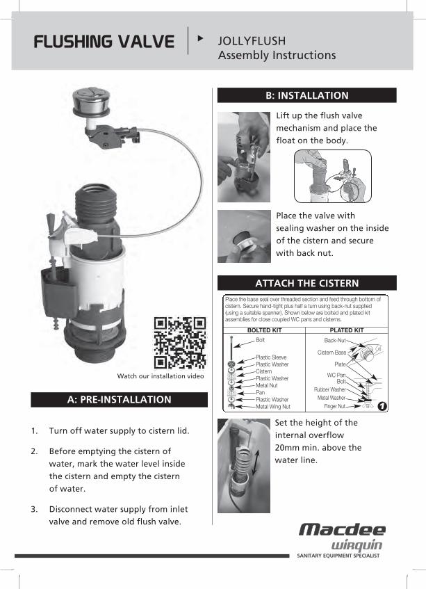
Place the base seal over threaded section and feed through bottom ofcistern. Secure hand-tight plus half a turn using back-nut supplied(using a suitable spanner). Shown below are bolted and plated kitassemblies for close coupled WC pans and cisterns.
BOLTED KIT PLATED KIT
Back-Nut
Cistern Base
Plate
WC PanBolt
Rubber WasherMetal Washer
Finger Nut 1
Bolt
Plastic SleevePlastic WasherCisternPlastic WasherMetal NutPanPlastic WasherMetal Wing Nut
Important for new installations : before turning water on, ensure that one cold water tap is open so that dirt and loose particles in the pipe work are flushed through the tap (we also recommend to flush through the water supply pipe to the cistern before connection is made.
INLET VALVE ▼ Assembly instruction leaflet• Jollyfill telescopic bottom entry inlet valve
SANITARY EQUIPMENT SPECIALIST
- Fit the filling valve. Ensure that the valve does not obstruct the flush mechanism. Do not overtighten the back nut.
2
If pressure < 1 bar (15 p.s.i) : cut here (gravity pressure/ header tank)
A : PRE-INSTALLATION
B : INSTALLATION
Turn off water supply to cistern and remove cistern lid.
Flush the cistern and remove any loose dirt from inside the tank.
Disconnect and remove the existing inlet valve.
Insert correct filter restrictor into threaded tail.
1
2
3
1
- Fit the filling valve. Ensure that the valve does not obstruct the flush mechanism. Do not overtighten the back nut.
2
If pressure < 1 bar (15 p.s.i) : cut here (gravity pressure/ header tank)
Fit the filling valve. Ensure that the valve does not obstruct the flush mechanism. Do not overtighten the back nut.
2
3
Connect water supply.4
JOLLYFILL TELESCOPIC BOTTOM ENTRY INLET VALVE
!
Turn on water supply. Allow the cistern to fill,5
Adjust the water level,A
WaterlineInternal overflow
2 cm
25 mm minimum from internal overflow to critical level (CL)
NOT OKOK
A
min 0 tomax150mm
on inlet valve.
OK
min 0 tomax150mm
If the water level is not correct, turn off water supply.Adjust the water level by : Turning slowly right or left to open.Pulling up the body of the telescopic part, (see pic B).Turning slowly right or left to lock. Turn on water supply.
B
BA
WaterlineInternal overflow
2 cm
25 mm minimum from internal overflow to critical level (CL)
NOT OKOK
A
min 0 tomax150mm
on inlet valve.
CYou can precisely adjust the float basin with the red rod. Unclip the red rod
Adjust the float basin Clip the red rod.
C
WaterlineInternal overflow
2 cm
25 mm minimum from internal overflow to critical level (CL)
NOT OKOK
A
min 0 tomax150mm
on inlet valve.
TROUBLE SHOOTING MAINTENANCE
FOR JOLLYFILL SIDE AND BOTTOM ENTRY VALVES
A B !Turn off water supply before any maintenance is carried out.
A B1 BOTTOM ENTRY 1 SIDE ENTRYA B2
2 Remove and wash the diaphragm and reassemble in reverse order.
(Scheme 9)
6
(Photo 8)
3 Remove and wash the filter restrictor and reassemble in reverse order.
6
A B
3
If pressure < 1 bar (15 p.s.i.) :cut here (gravity pressure / header tank)
Adjustment rod
Float
Float basin
Threaded tailRubber washer
Back nut
Filter restrictor
!
NOT OKOK

Observation Problems Solution
Water is leaking back into the pan
The cable is obstructed Pick up the cistern lid slightly and push button to check that the flush valve is moving up and down and not obstructed by the inlet valve or touching the cistern wall or kinked or twisted cable
The water level in the cistern is above the internal overflow.
Check that the overflow is set 20mm above the waterline marked on the cistern.
Seal not sitting flat on the valve base.
Check the seal is clean from debris. Take off and clean then refit.
Not flushing Button is not working. Locate the button and push witha click into the cable base.
Make sure the cable is free andnot kinked.
Important for new installations : before turning water on, ensure that one cold water tap is open so that dirt and loose particles in the pipe work are flushed through the tap (we also recommend to flush through the water supply pipe to the cistern before connection is made.
INLET VALVE ▼ Assembly instruction leaflet• Jollyfill telescopic bottom entry inlet valve
SANITARY EQUIPMENT SPECIALIST
- Fit the filling valve. Ensure that the valve does not obstruct the flush mechanism. Do not overtighten the back nut.
2
If pressure < 1 bar (15 p.s.i) : cut here (gravity pressure/ header tank)
A : PRE-INSTALLATION
B : INSTALLATION
Turn off water supply to cistern and remove cistern lid.
Flush the cistern and remove any loose dirt from inside the tank.
Disconnect and remove the existing inlet valve.
Insert correct filter restrictor into threaded tail.
1
2
3
1
- Fit the filling valve. Ensure that the valve does not obstruct the flush mechanism. Do not overtighten the back nut.
2
If pressure < 1 bar (15 p.s.i) : cut here (gravity pressure/ header tank)
Fit the filling valve. Ensure that the valve does not obstruct the flush mechanism. Do not overtighten the back nut.
2
3
Connect water supply.4
JOLLYFILL TELESCOPIC BOTTOM ENTRY INLET VALVE
!
Turn on water supply. Allow the cistern to fill,5
Adjust the water level,A
WaterlineInternal overflow
2 cm
25 mm minimum from internal overflow to critical level (CL)
NOT OKOK
A
min 0 tomax150mm
on inlet valve.
OK
min 0 tomax150mm
If the water level is not correct, turn off water supply.Adjust the water level by : Turning slowly right or left to open.Pulling up the body of the telescopic part, (see pic B).Turning slowly right or left to lock. Turn on water supply.
B
BA
WaterlineInternal overflow
2 cm
25 mm minimum from internal overflow to critical level (CL)
NOT OKOK
A
min 0 tomax150mm
on inlet valve.
CYou can precisely adjust the float basin with the red rod. Unclip the red rod
Adjust the float basin Clip the red rod.
C
WaterlineInternal overflow
2 cm
25 mm minimum from internal overflow to critical level (CL)
NOT OKOK
A
min 0 tomax150mm
on inlet valve.
TROUBLE SHOOTING MAINTENANCE
FOR JOLLYFILL SIDE AND BOTTOM ENTRY VALVES
A B !Turn off water supply before any maintenance is carried out.
A B1 BOTTOM ENTRY 1 SIDE ENTRYA B2
2 Remove and wash the diaphragm and reassemble in reverse order.
(Scheme 9)
6
(Photo 8)
3 Remove and wash the filter restrictor and reassemble in reverse order.
6
A B
3
If pressure < 1 bar (15 p.s.i.) :cut here (gravity pressure / header tank)
Adjustment rod
Float
Float basin
Threaded tailRubber washer
Back nut
Filter restrictor
!
NOT OKOK

SANITARY EQUIPMENT SPECIALIST
WIRQUIN LTD - Warmsworth Halt Industrial Estate - Warmsworth - Doncaster DN4 9LS - UNITED KINGDOM Sales / Aftersales: ) 0044 (0)333 222 4488 * [email protected] / [email protected] www.wirquin.co.uk
CodeIssue No.Date
2403081
June/2016
TROUBLESHOOTER
THE CISTERN IS NOT FILLING
LEAK FROM THE FLUSHING INTERNAL VALVE OVERFLOW
THE FULL FLUSH OR THE HALF FLUSH IS NOT SUFFICIENT
THE INLET VALVE DOES NOT SHUT OFF OR SHUTS OFF VERY SLOWLY (At the installation)
THE INLET VALVE DOES NOT SHUT OFF OR SHUTS OFF VERY SLOWLY (after a few months of using)
THE CISTERN IF FILLING VERY SLOWLY (at the installation)
PROBLEM CAUSE SOLUTIONS
• Turn on water supply
• The inlet valve is shut off and does not open
• The high level of the float basin is higher than the top level of the overflow
• The water height is too low in the tank
• The float is completely outside the float basin.
• The diaphragm has some debris because the filter is missing.
• The diaphragm has some debris because the dirt and loose particles in the pipe work have not been flushed through the tap before having turned the water on (the filter has well been assembled on the valve).
• The filter restrictor has some debris.
• The diaphragm has some debris.
• The diaphragm is damaged.
• The flow restrictor has not been fitted in accordance with the instructions.
• The diaphragm has some debris because the filter restrictor is missing.
• The diaphragm has some debris because the dirt and loose particles in the pipe work have not been flushed through the tap before having turned water on (the filter has been assembled on the valve.).
• Turn on water supply
• Check all moving components move up and down freely. If not unclip the rod from the float (photos 1 and 2). Reclip it in correct way (photos 3 and 4).
• Flush the cistern. Turn the water supply off. Unclip the adjustment rod from the float (photos 1 and 2).
• Push on the float in ordere to make it go down.
• Clip the adjustment rod on the float in the correct way (photos 3 and 4).
• Check that the water level is right (scheme 5).
• Flush the cistern. Turn off water supply. Unclip the adjustment rod from the float (photos 1 and 2)
• Raise the level of the float basin on the body
• Re clip the adjustment rod on the float in the correct way (photos 3 and 4).
• Check the flush is sufficient.
• Unclip the red adjustment rod from the float (photos 1 and 2). Reclip it in correct way (photos 3 and 4).
• Put the filter restrictor in accordance with the instructions (Scheme 6).
• Wash the diaphragm in conformity with the instructions described on the back. Before turning water on, ensure that one cold water tap is open so that dirt and loose particles in the pipe work are flushed through the tap (Scheme 7).
• Wash the filter restrictor (photo 10) in conformity with the instructions described on the back.
• Wash the diaphragm (Scheme 7) in conformity with the instructions described on the back.
• Call after self service number (Helpline Number).
• Put the filter restrictor in accordance with the instructions (Scheme 6).
• Put the filter restrictor in accordance with the instructions (Scheme 6).
• Wash the diaphragm in conformity with the instructions described on the back (Scheme 7). Before turning water on, ensure that one cold water tap is open so that dirt and loose particles in the pipe work are flushed through the tap.
(Scheme 9)
6
(Photo 8)THE CISTERN IS NOT FILLING OR IS FILLING VERY SLOWLY(After a few months of using)
THE CISTERN IS FILLING TOO QUICKLY
LEAK FROM THE BACK NUT
• The diaphragm has some debris
• The diaphragm is damaged
• The filter restrictor has not been fitted in accordance the instructions
• The back nut is not tight enough
• The rubber washer is missing on the inlet valve
• The rubber washer is damaged
• Wash the diaphragm (Scheme 7) in conformity with the instructions described on the back.
• Call after self service number (Helpline number).
• Put the filter restrictor in accordance with the instructions (Scheme 6).
• Re tighten the back nut (photo 8).
• Assemble the rubber washer on the valve (Scheme 9).
• Call after service number (Helpline number).
(photo 1/2)
(photo 4)
Important for new installations : before turning water on, ensure that one cold water tap is open so that dirt and loose particles in the pipe work are flushed through the tap (we also recommend to flush through the water supply pipe to the cistern before connection is made.
INLET VALVE ▼ Assembly instruction leaflet• Jollyfill telescopic bottom entry inlet valve
SANITARY EQUIPMENT SPECIALIST
- Fit the filling valve. Ensure that the valve does not obstruct the flush mechanism. Do not overtighten the back nut.
2
If pressure < 1 bar (15 p.s.i) : cut here (gravity pressure/ header tank)
A : PRE-INSTALLATION
B : INSTALLATION
Turn off water supply to cistern and remove cistern lid.
Flush the cistern and remove any loose dirt from inside the tank.
Disconnect and remove the existing inlet valve.
Insert correct filter restrictor into threaded tail.
1
2
3
1
- Fit the filling valve. Ensure that the valve does not obstruct the flush mechanism. Do not overtighten the back nut.
2
If pressure < 1 bar (15 p.s.i) : cut here (gravity pressure/ header tank)
Fit the filling valve. Ensure that the valve does not obstruct the flush mechanism. Do not overtighten the back nut.
2
3
Connect water supply.4
JOLLYFILL TELESCOPIC BOTTOM ENTRY INLET VALVE
!
Turn on water supply. Allow the cistern to fill,5
Adjust the water level,A
WaterlineInternal overflow
2 cm
25 mm minimum from internal overflow to critical level (CL)
NOT OKOK
A
min 0 tomax150mm
on inlet valve.
OK
min 0 tomax150mm
If the water level is not correct, turn off water supply.Adjust the water level by : Turning slowly right or left to open.Pulling up the body of the telescopic part, (see pic B).Turning slowly right or left to lock. Turn on water supply.
B
BA
WaterlineInternal overflow
2 cm
25 mm minimum from internal overflow to critical level (CL)
NOT OKOK
A
min 0 tomax150mm
on inlet valve.
CYou can precisely adjust the float basin with the red rod. Unclip the red rod
Adjust the float basin Clip the red rod.
C
WaterlineInternal overflow
2 cm
25 mm minimum from internal overflow to critical level (CL)
NOT OKOK
A
min 0 tomax150mm
on inlet valve.
TROUBLE SHOOTING MAINTENANCE
FOR JOLLYFILL SIDE AND BOTTOM ENTRY VALVES
A B !Turn off water supply before any maintenance is carried out.
A B1 BOTTOM ENTRY 1 SIDE ENTRYA B2
2 Remove and wash the diaphragm and reassemble in reverse order.
(Scheme 9)
6
(Photo 8)
3 Remove and wash the filter restrictor and reassemble in reverse order.
6
A B
3
If pressure < 1 bar (15 p.s.i.) :cut here (gravity pressure / header tank)
Adjustment rod
Float
Float basin
Threaded tailRubber washer
Back nut
Filter restrictor
!
NOT OKOK
Code
Issue No.
Date
240323
1
July 2016