Embed Size (px)
Citation preview
Joint Tactical Radio Joint Tactical Radio SystemSystem
John D. Bard, Ph.D.Space Coast Communication Systems, Inc.
100 Rialto Place Suite 730Melbourne, FL 32901W +1 (321) 951-8320F +1 (321) 951-9920
[email protected]://www.spacecoastcomm.com/
Copyright 2003, Space Coast Communication Systems, Inc. 1
Table of Contents
• JTRS –Today and Tomorrow• JTRS Technology Challenges• JTRS 101 - Understanding SDR • JTRS Clusters• The Software Communications Architecture• JTRS Compliance• JTRS Waveform Applications • JTRS Lessons Learned
Copyright 2003, Space Coast Communication Systems, Inc. 2
JTRS Mission Statement• Provide a family of interoperable radio sets• Capable of loading multiple waveforms• Support Joint operations• Capability to transmit, receive, bridge, and gateway
between– waveforms– network protocols – across service boundaries– voice, video, and data
• Allow collaboration between commanders and staffs• Perform the same functions and missions supported by
the legacy radios
Copyright 2003, Space Coast Communication Systems, Inc. 3
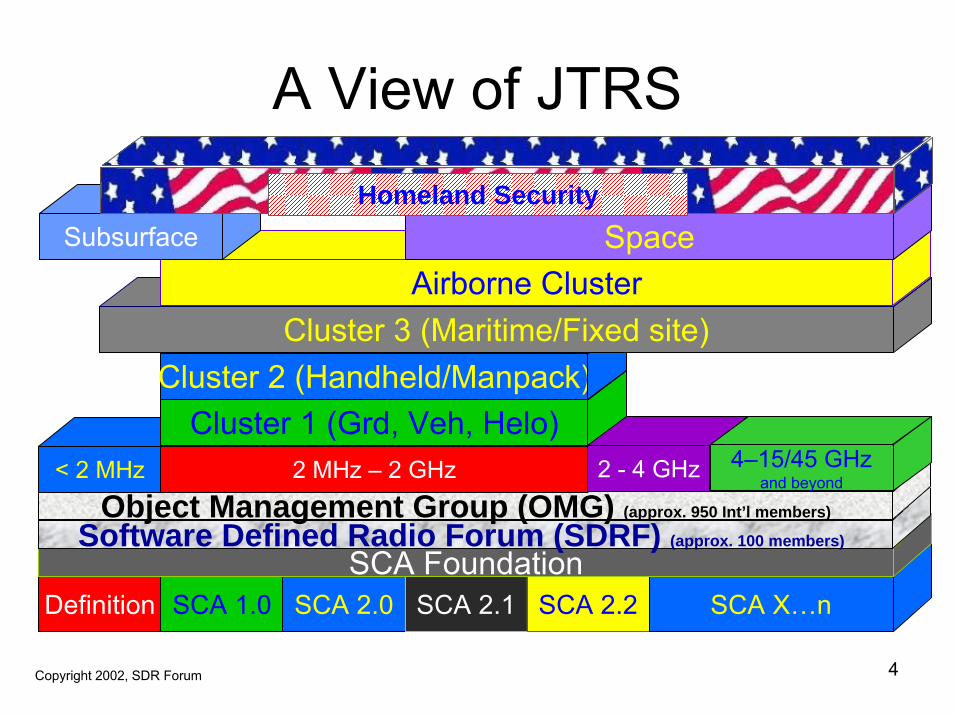
A View of JTRS
Definition SCA 1.0 SCA 2.0 SCA 2.1 SCA 2.2 SCA X…nSCA Foundation
Software Defined Radio Forum (SDRF) (approx. 100 members)
Object Management Group (OMG) (approx. 950 Int’l members)
< 2 MHz 2 MHz – 2 GHz 2 - 4 GHz
Cluster 1 (Grd, Veh, Helo)Cluster 2 (Handheld/Manpack)
Cluster 3 (Maritime/Fixed site)Airborne Cluster
SpaceSubsurface
4–15/45 GHzand beyond
Homeland Security
Copyright 2003, Space Coast Communication Systems, Inc. 4Copyright 2002, SDR Forum
Background and Current Status of JTRS
• Architecture Study, 1998– General Dynamics Decision Systems Team– Raytheon Team
• Architecture Definition, Step 2A,’99-’01– Raytheon Team, > 5 team members
• Architecture Validation, Step 2B,’00-’02– Multiple, > 6 Awards plus Follow-On
• Cluster One Award, 2002 – Boeing - Anaheim, Prime Integrator– H/W&S/W Providers, Collins & BAE Systems
Copyright 2003, Space Coast Communication Systems, Inc. 5
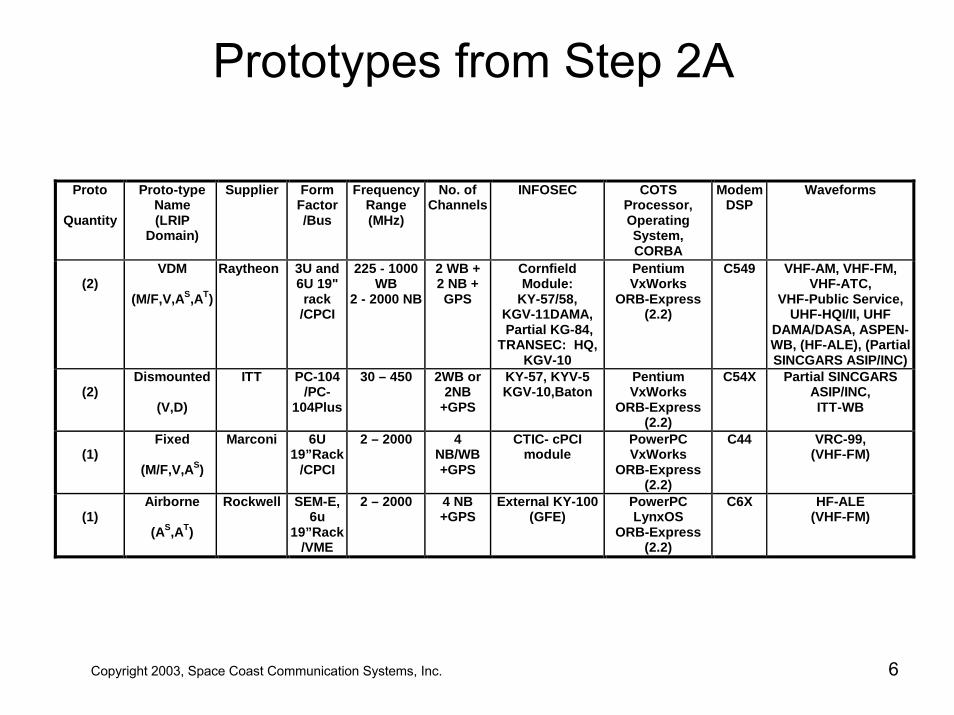
Prototypes from Step 2A
Proto
Quantity
Proto-type Name (LRIP
Domain)
Supplier Form Factor /Bus
FrequencyRange (MHz)
No. of Channels
INFOSEC COTS Processor, Operating System, CORBA
Modem DSP
Waveforms
(2)
VDM (M/F,V,AS,AT)
Raytheon 3U and 6U 19" rack
/CPCI
225 - 1000 WB
2 - 2000 NB
2 WB + 2 NB + GPS
Cornfield Module:
KY-57/58, KGV-11DAMA, Partial KG-84,
TRANSEC: HQ, KGV-10
Pentium VxWorks
ORB-Express (2.2)
C549 VHF-AM, VHF-FM, VHF-ATC,
VHF-Public Service, UHF-HQI/II, UHF
DAMA/DASA, ASPEN-WB, (HF-ALE), (Partial SINCGARS ASIP/INC)
(2)
Dismounted
(V,D)
ITT PC-104/PC-
104Plus
30 – 450
2WB or 2NB
+GPS
KY-57, KYV-5 KGV-10,Baton
Pentium VxWorks
ORB-Express (2.2)
C54X Partial SINCGARS ASIP/INC, ITT-WB
(1)
Fixed
(M/F,V,AS)
Marconi 6U 19”Rack
/CPCI
2 – 2000 4 NB/WB+GPS
CTIC- cPCI module
PowerPC VxWorks
ORB-Express (2.2)
C44 VRC-99, (VHF-FM)
(1)
Airborne
(AS,AT)
Rockwell SEM-E,6u
19”Rack/VME
2 – 2000 4 NB +GPS
External KY-100 (GFE)
PowerPC LynxOS
ORB-Express (2.2)
C6X HF-ALE (VHF-FM)
Copyright 2003, Space Coast Communication Systems, Inc. 6
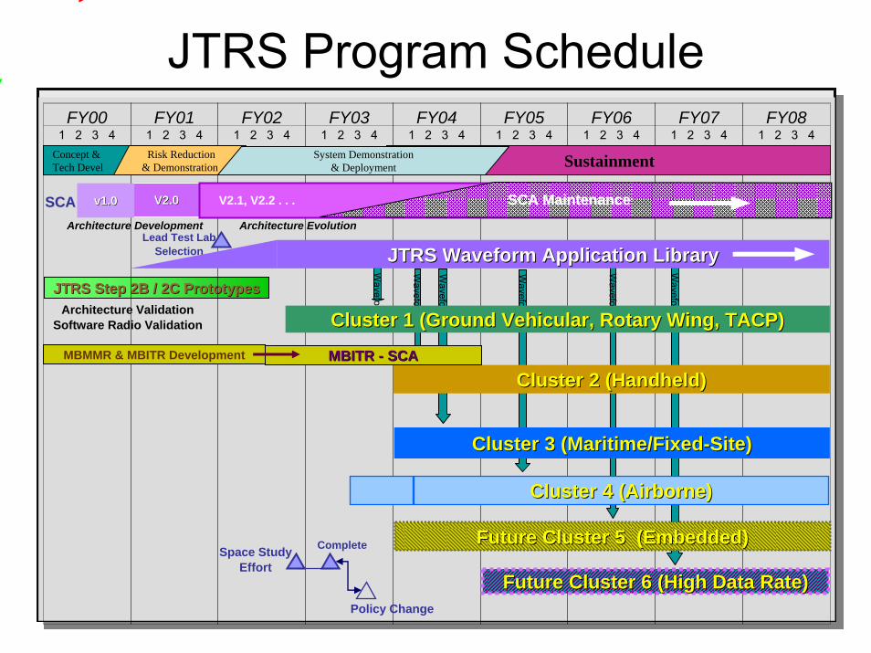
JTRS Program Schedule
Copyright 2003, Space Coast Communication Systems, Inc. 7
Waveform
Waveform
Waveform
JTRS Step 2B / 2C PrototypesJTRS Step 2B / 2C Prototypes
FY001 2 3 4
FY011 2 3 4
FY021 2 3 4
FY031 2 3 4
FY041 2 3 4
FY051 2 3 4
FY061 2 3 4
FY071 2 3 4
FY081 2 3 4
Waveform
Waveform
Concept & Tech Devel
Risk Reduction& Demonstration SustainmentSystem Demonstration
& Deployment
V2.0V2.0v1.0v1.0SCASCAArchitecture Development Architecture Evolution
Architecture ValidationSoftware Radio Validation
Future Cluster 6 (High Data Rate)Future Cluster 6 (High Data Rate)
Lead Test LabSelection
V2.1, V2.2 . . . SCA MaintenanceSCA Maintenance
Waveform
Cluster 1 (Ground Vehicular, Rotary Wing, TACP)Cluster 1 (Ground Vehicular, Rotary Wing, TACP)
JTRS Waveform Application LibraryJTRS Waveform Application Library
Cluster 2 (Handheld)Cluster 2 (Handheld)
Cluster 3 (Maritime/FixedCluster 3 (Maritime/Fixed--Site)Site)
Future Cluster 5 (Embedded)Future Cluster 5 (Embedded)Space Study
Effort
Policy Change
Complete
MBMMR & MBITR Development MBITR MBITR -- SCASCA
Cluster 4 (Airborne)Cluster 4 (Airborne)
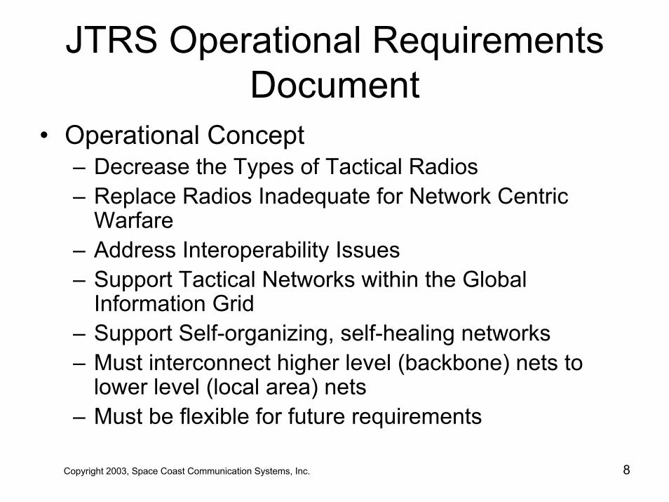
JTRS Operational RequirementsDocument
• Operational Concept– Decrease the Types of Tactical Radios– Replace Radios Inadequate for Network Centric
Warfare– Address Interoperability Issues– Support Tactical Networks within the Global
Information Grid– Support Self-organizing, self-healing networks– Must interconnect higher level (backbone) nets to
lower level (local area) nets– Must be flexible for future requirements
Copyright 2003, Space Coast Communication Systems, Inc. 8
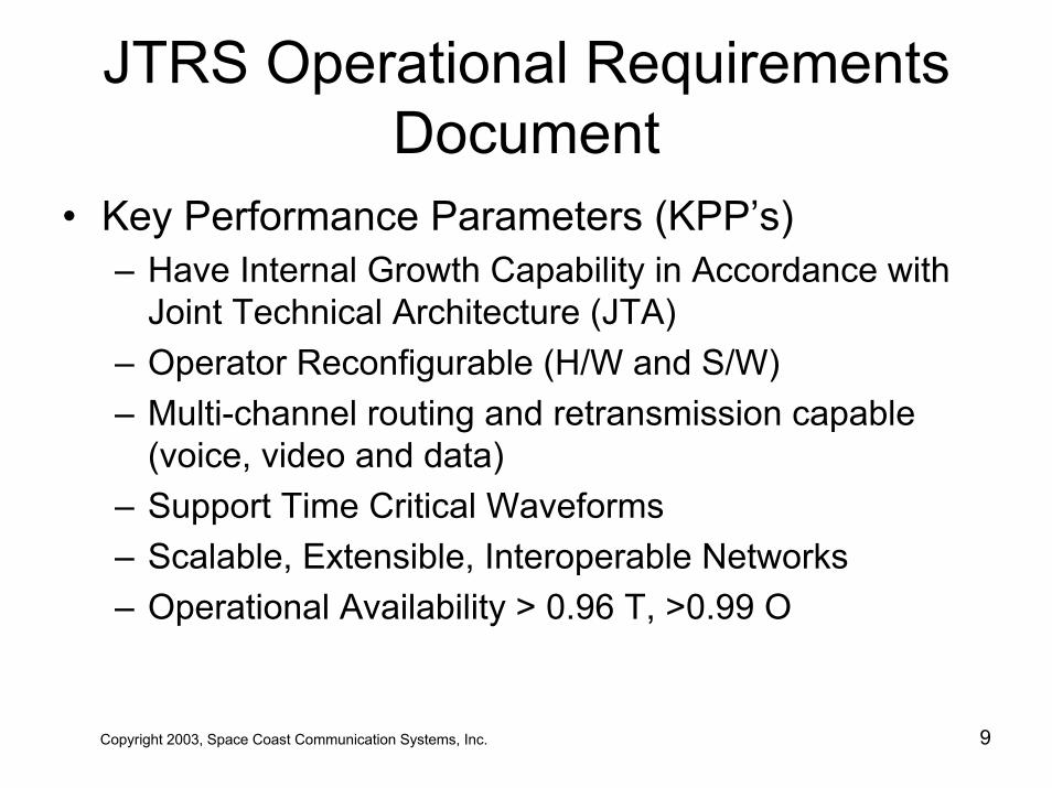
JTRS Operational RequirementsDocument
• Key Performance Parameters (KPP’s)– Have Internal Growth Capability in Accordance with
Joint Technical Architecture (JTA)– Operator Reconfigurable (H/W and S/W)– Multi-channel routing and retransmission capable
(voice, video and data)– Support Time Critical Waveforms– Scalable, Extensible, Interoperable Networks– Operational Availability > 0.96 T, >0.99 O
Copyright 2003, Space Coast Communication Systems, Inc. 9
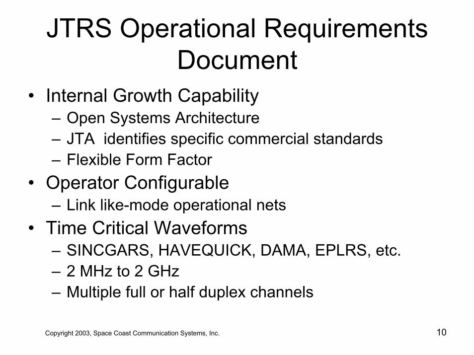
JTRS Operational RequirementsDocument
• Internal Growth Capability– Open Systems Architecture– JTA identifies specific commercial standards– Flexible Form Factor
• Operator Configurable– Link like-mode operational nets
• Time Critical Waveforms– SINCGARS, HAVEQUICK, DAMA, EPLRS, etc.– 2 MHz to 2 GHz– Multiple full or half duplex channels
Copyright 2003, Space Coast Communication Systems, Inc. 10
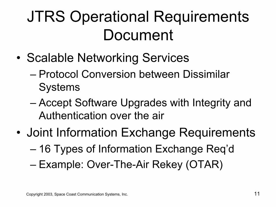
JTRS Operational RequirementsDocument
• Scalable Networking Services– Protocol Conversion between Dissimilar
Systems– Accept Software Upgrades with Integrity and
Authentication over the air• Joint Information Exchange Requirements
– 16 Types of Information Exchange Req’d– Example: Over-The-Air Rekey (OTAR)
Copyright 2003, Space Coast Communication Systems, Inc. 11
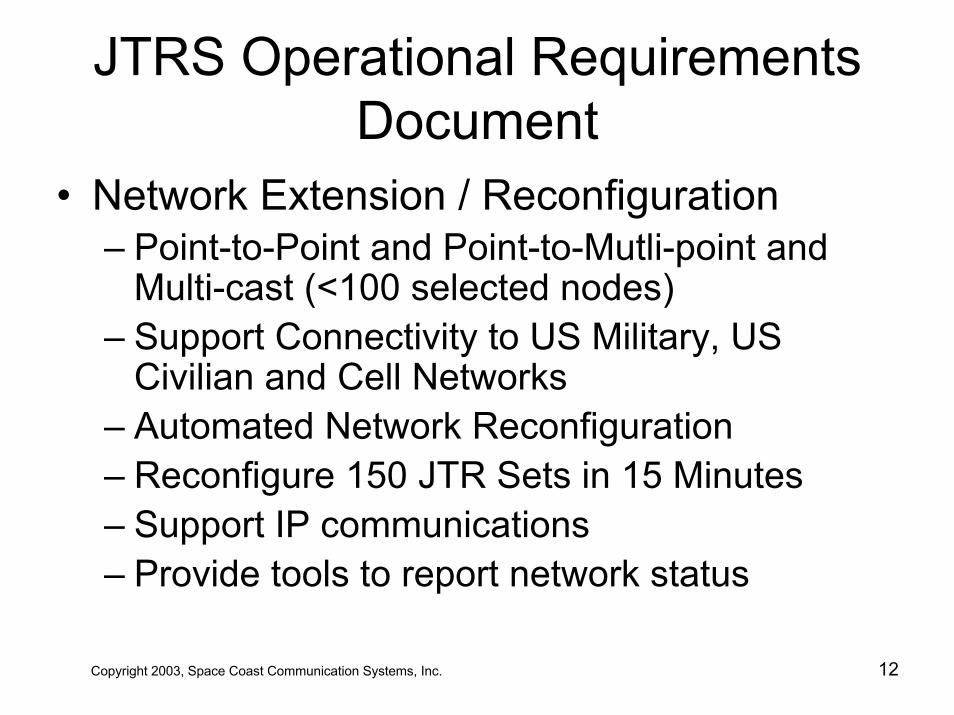
JTRS Operational RequirementsDocument
• Network Extension / Reconfiguration– Point-to-Point and Point-to-Mutli-point and
Multi-cast (<100 selected nodes)– Support Connectivity to US Military, US
Civilian and Cell Networks– Automated Network Reconfiguration– Reconfigure 150 JTR Sets in 15 Minutes– Support IP communications– Provide tools to report network status
Copyright 2003, Space Coast Communication Systems, Inc. 12
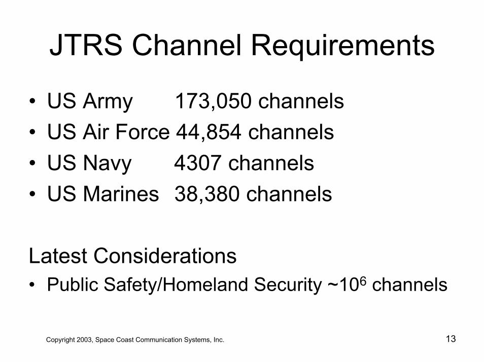
JTRS Channel Requirements
• US Army 173,050 channels• US Air Force 44,854 channels• US Navy 4307 channels• US Marines 38,380 channels
Latest Considerations• Public Safety/Homeland Security ~106 channels
Copyright 2003, Space Coast Communication Systems, Inc. 13
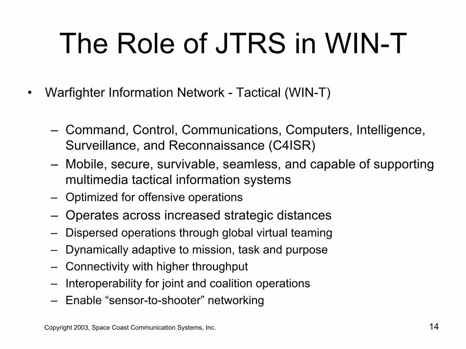
The Role of JTRS in WIN-T• Warfighter Information Network - Tactical (WIN-T)
– Command, Control, Communications, Computers, Intelligence, Surveillance, and Reconnaissance (C4ISR)
– Mobile, secure, survivable, seamless, and capable of supporting multimedia tactical information systems
– Optimized for offensive operations– Operates across increased strategic distances– Dispersed operations through global virtual teaming– Dynamically adaptive to mission, task and purpose– Connectivity with higher throughput– Interoperability for joint and coalition operations– Enable “sensor-to-shooter” networking
Copyright 2003, Space Coast Communication Systems, Inc. 14
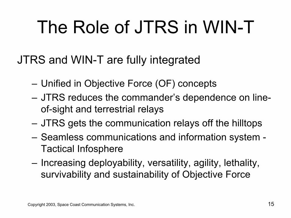
The Role of JTRS in WIN-T
JTRS and WIN-T are fully integrated
– Unified in Objective Force (OF) concepts– JTRS reduces the commander’s dependence on line-
of-sight and terrestrial relays– JTRS gets the communication relays off the hilltops– Seamless communications and information system -
Tactical Infosphere– Increasing deployability, versatility, agility, lethality,
survivability and sustainability of Objective Force
Copyright 2003, Space Coast Communication Systems, Inc. 15
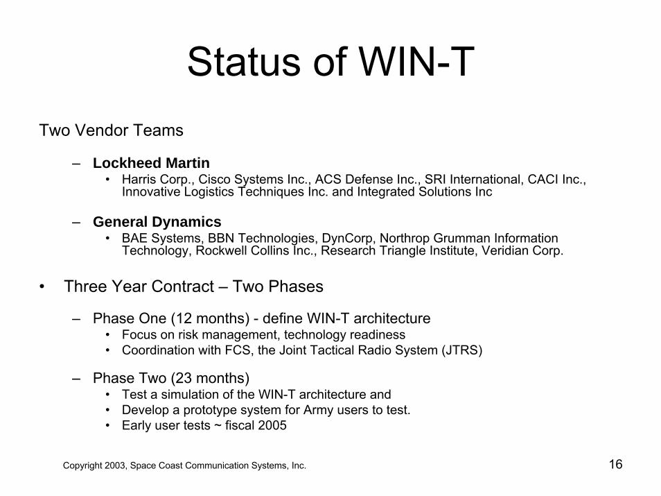
Status of WIN-TTwo Vendor Teams
– Lockheed Martin• Harris Corp., Cisco Systems Inc., ACS Defense Inc., SRI International, CACI Inc.,
Innovative Logistics Techniques Inc. and Integrated Solutions Inc
– General Dynamics• BAE Systems, BBN Technologies, DynCorp, Northrop Grumman Information
Technology, Rockwell Collins Inc., Research Triangle Institute, Veridian Corp.
• Three Year Contract – Two Phases
– Phase One (12 months) - define WIN-T architecture • Focus on risk management, technology readiness • Coordination with FCS, the Joint Tactical Radio System (JTRS)
– Phase Two (23 months)• Test a simulation of the WIN-T architecture and• Develop a prototype system for Army users to test. • Early user tests ~ fiscal 2005
Copyright 2003, Space Coast Communication Systems, Inc. 16
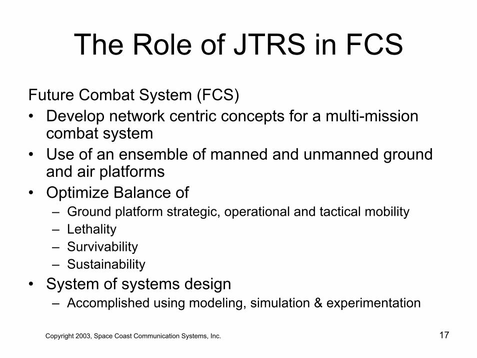
The Role of JTRS in FCSFuture Combat System (FCS)• Develop network centric concepts for a multi-mission
combat system• Use of an ensemble of manned and unmanned ground
and air platforms• Optimize Balance of
– Ground platform strategic, operational and tactical mobility– Lethality– Survivability– Sustainability
• System of systems design – Accomplished using modeling, simulation & experimentation
Copyright 2003, Space Coast Communication Systems, Inc. 17
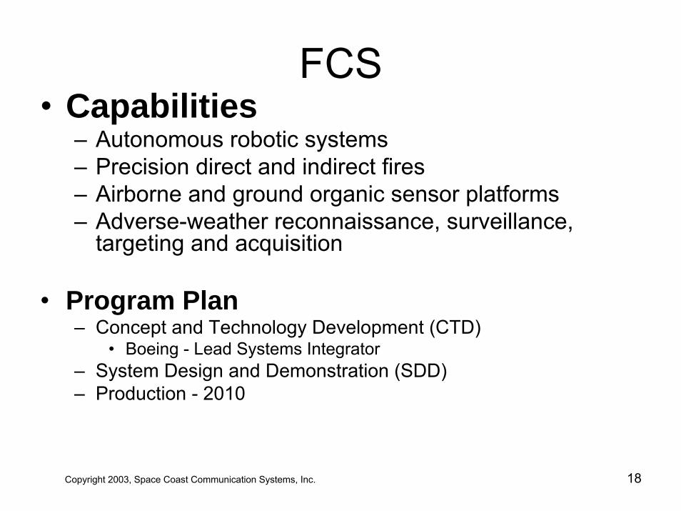
FCS• Capabilities
– Autonomous robotic systems – Precision direct and indirect fires – Airborne and ground organic sensor platforms– Adverse-weather reconnaissance, surveillance,
targeting and acquisition
• Program Plan– Concept and Technology Development (CTD)
• Boeing - Lead Systems Integrator– System Design and Demonstration (SDD)– Production - 2010
Copyright 2003, Space Coast Communication Systems, Inc. 18
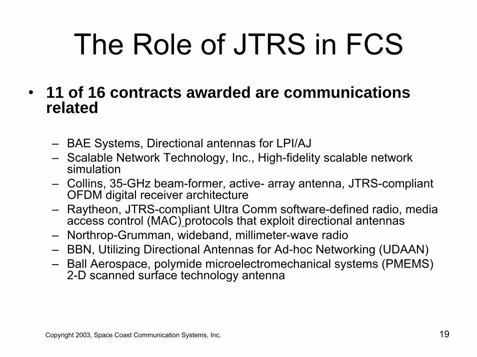
The Role of JTRS in FCS• 11 of 16 contracts awarded are communications
related
– BAE Systems, Directional antennas for LPI/AJ– Scalable Network Technology, Inc., High-fidelity scalable network
simulation– Collins, 35-GHz beam-former, active- array antenna, JTRS-compliant
OFDM digital receiver architecture– Raytheon, JTRS-compliant Ultra Comm software-defined radio, media
access control (MAC) protocols that exploit directional antennas – Northrop-Grumman, wideband, millimeter-wave radio– BBN, Utilizing Directional Antennas for Ad-hoc Networking (UDAAN)– Ball Aerospace, polymide microelectromechanical systems (PMEMS)
2-D scanned surface technology antenna
Copyright 2003, Space Coast Communication Systems, Inc. 19
The Role of JTRS in FCS
• 11 of 16 contracts awarded are communications related (cont’d)– Titan/Atlantic Aerospace Corporation, UHF array
over a high impedance surface– Georgia Institute of Technology Research Institute,
micro-switched percolating reconfigurable aperture development
– General Dynamics, high-capacity, low probability of detection technologies
– Ipitek, low phase-noise millimeter-wave source
Copyright 2003, Space Coast Communication Systems, Inc. 20
The Role of JTRS in GIG• Global Information Grid
– Implements Joint Vision 2010• Dominant maneuver• Precision engagement• Full dimensional protection• Focused logistics
– GIG Architecture (v1.0)– Single Architecture - Three views:
• Operational Architecture (OA) View • Systems Architecture (SA) View• Technical Architecture View (TA)
– The TA view is the Joint Technical Architecture (JTA)
Copyright 2003, Space Coast Communication Systems, Inc. 21
The Role of JTRS in JTA• Joint Technical Architecture
– Technical View of the Global Information Grid– Defines the service areas, interfaces, and standards
applicable to all DoD systems• Two Parts
– JTA Core and JTA domains• Domains: C4ISR, Combat Support, Modeling and Simulation;
and Weapon Systems, Intelligence, Surveillance and Reconnaissance (ISR)
• JTA standards identify commercial off-the-shelf implementations available from multiple vendors
– Elements of JTRS SCA all called out in the JTA, namely POSIX and CORBA
Copyright 2003, Space Coast Communication Systems, Inc. 22
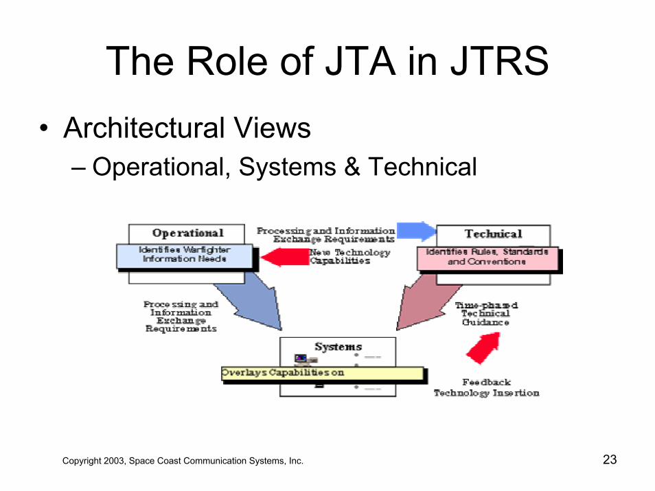
The Role of JTA in JTRS• Architectural Views
– Operational, Systems & Technical
Copyright 2003, Space Coast Communication Systems, Inc. 23
The Big Picture• Interoperability Path Forward
– WIN-T – the bandwidth to interoperate – Military Satellite Communications – key enabler– JTRS – interoperable wireless communications– ABCS SSEI – eliminating system stovepipes– FCS – the ultimate in interoperability
• Need major advances in interoperability standards– current process too slow & ad hoc– years to make changes
• Testing environment needs to be standardized– Reusable simulation / stimulation suite of tools
• Joint Forces Command– Interoperability experimentation before fielding
Copyright 2003, Space Coast Communication Systems, Inc. 24
JTRS Responsibilities
Copyright 2003, Space Coast Communication Systems, Inc. 25
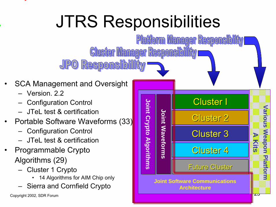
• SCA Management and Oversight– Version. 2.2– Configuration Control– JTeL test & certification
• Portable Software Waveforms (33)– Configuration Control– JTeL test & certification
• Programmable CryptoAlgorithms (29)– Cluster 1 Crypto
• 14 Algorithms for AIM Chip only– Sierra and Cornfield Crypto
• Required in near future
Cluster ICluster I
Cluster 2Cluster 2
Cluster 3Cluster 3
Cluster 4Cluster 4
Future ClusterFuture ClusterFuture Cluster
Joint Waveform
sJoint W
aveforms
Joint Crypto A
lgorithms
Joint Crypto A
lgorithms
Joint Software Communications Architecture
Various Weapon Platform
A K
its
Copyright 2002, SDR Forum
JTRS Compliance
• Software Communications Architecture– Over a thousand “shall” requirements– SCA v2.1 has been adopted by the SDR Forum
• Partial Solution: By itself does not ensure portability• Defining Layered Applications Program Interfaces (API’s)
– OMG has adopted slices of the SCA1. Platform Independent Model2. Software Radio RFP3. Lightweight CORBA Components Model RFP4. Deployment and Configuration RFP5. Lightweight Log Services (Approved, Nov 2002)
Copyright 2003, Space Coast Communication Systems, Inc. 26
JTRS: Test and Evaluation• JTRS Technology Laboratory (JTeL)
– SPAWAR (San Diego and Charleston, SC)– Responsibilities include
• Complete SCA Compliance testing• Waveform Performance testing• Complete Security testing• Provide waveform repository and maintain
waveforms for their lifetime• Provide for representative JTR Set• Provide for pilot JTRS waveforms• Facilitate a distributed test environment
Copyright 2003, Space Coast Communication Systems, Inc. 27
Copyright 2003, Space Coast Communication Systems, Inc. 28
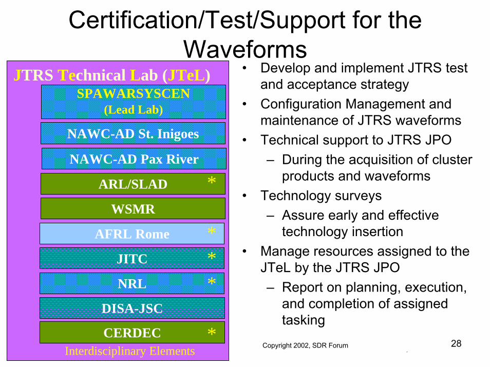
Certification/Test/Support for the Waveforms
SPAWARSYSCEN(Lead Lab)
ARL/SLAD
NAWC-AD Pax River
NAWC-AD St. Inigoes
AFRL Rome
NRL
JITC
WSMR
CERDEC
DISA-JSC
JTRS Technical Lab (JTeL)
Interdisciplinary Elements
• Develop and implement JTRS test and acceptance strategy
• Configuration Management and maintenance of JTRS waveforms
• Technical support to JTRS JPO – During the acquisition of cluster
products and waveforms• Technology surveys
– Assure early and effective technology insertion
• Manage resources assigned to the JTeL by the JTRS JPO – Report on planning, execution,
and completion of assigned tasking
* Center of Excellence Selectees, to date.
*
***
*Copyright 2002, SDR Forum
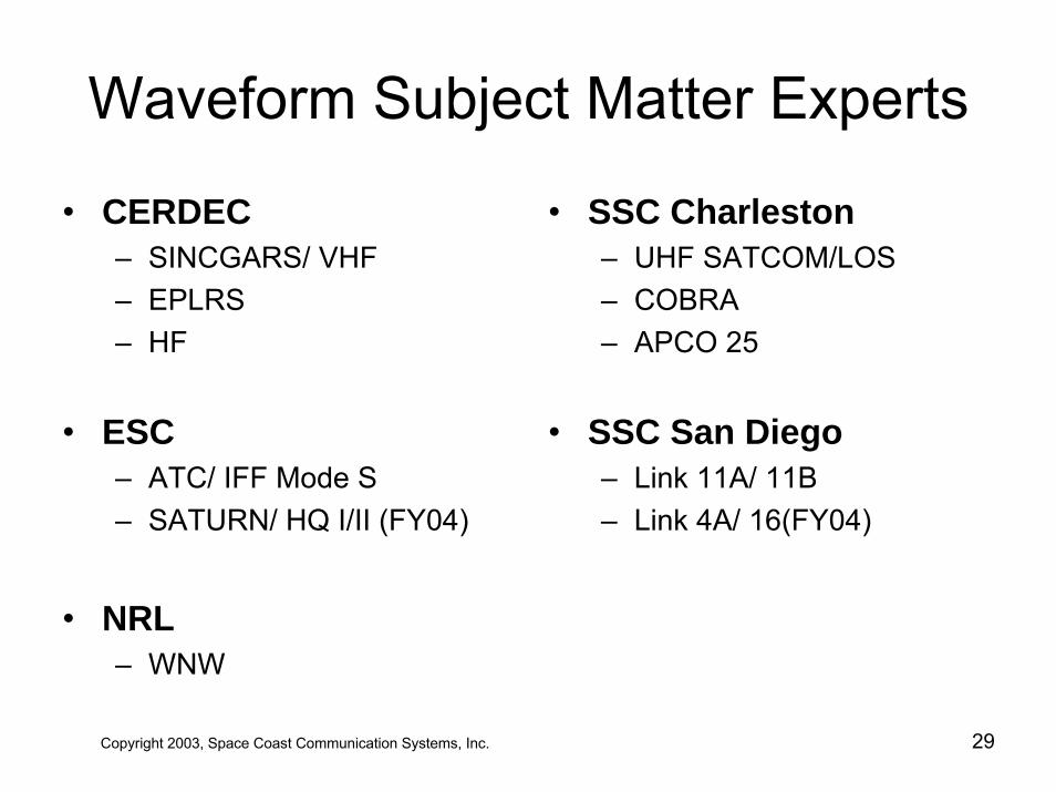
Waveform Subject Matter Experts
• CERDEC– SINCGARS/ VHF– EPLRS– HF
• ESC– ATC/ IFF Mode S – SATURN/ HQ I/II (FY04)
• NRL– WNW
• SSC Charleston– UHF SATCOM/LOS– COBRA– APCO 25
• SSC San Diego– Link 11A/ 11B– Link 4A/ 16(FY04)
Copyright 2003, Space Coast Communication Systems, Inc. 29
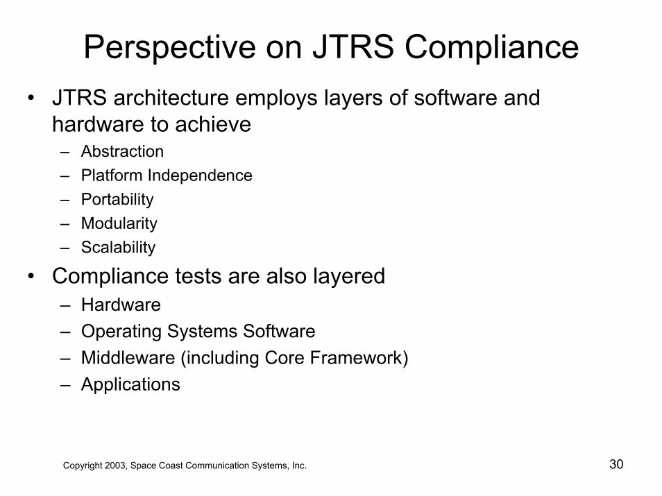
Perspective on JTRS Compliance• JTRS architecture employs layers of software and
hardware to achieve– Abstraction– Platform Independence– Portability– Modularity– Scalability
• Compliance tests are also layered– Hardware– Operating Systems Software– Middleware (including Core Framework)– Applications
Copyright 2003, Space Coast Communication Systems, Inc. 30
Table of Contents
• JTRS –Today and Tomorrow• JTRS Technology Challenges• JTRS 101 - Understanding SDR • JTRS Clusters• The Software Communications Architecture• JTRS Compliance• JTRS Waveform Applications • JTRS Lessons Learned
Copyright 2003, Space Coast Communication Systems, Inc. 31
JTRS Technology Challenges
Copyright 2003, Space Coast Communication Systems, Inc. 32
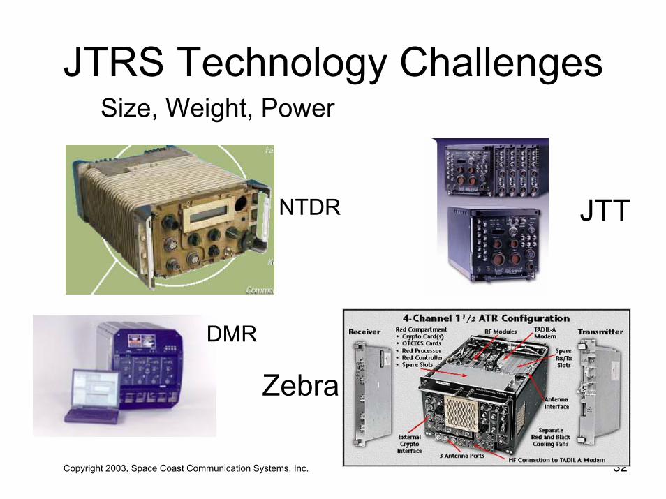
Size, Weight, Power
Zebra
NTDR
DMR
JTT
JTRS Technology Challenges• Physics, Analog RF Section
• The notion of SDR requires state-of-the-art analog performance of components from the antenna through to the digitizers
• JTRS requires 2 MHz to 2 GHz with ALL thesensitivity, dynamic range, bandwidth control, adjacent channel rejection, elimination of spurious emissions, frequency hop settling times, and terminal latencies
of ALL the Legacy terminals it replaces
Copyright 2003, Space Coast Communication Systems, Inc. 33
JTRS Technology Challenges• Improvement of Standards
– SCA is only part of the solution for JTA Compliance– Lacking Applications Program Interface– Standardized RF Hardware Interfaces– Accommodating other (non-CORBA) middleware's– Lack of Hardware-based Timing Services
• Lack of Software and Emulator Tools• Clear delineation of testability requirements
– Infrastructure vs. Waveforms
• Lack of Metric for Infrastructure Capability/Stability• Modem development largely considered proprietary • No standards for Waveform Description• Not yet reliable enough for ATC usage (Cluster 4)
Copyright 2003, Space Coast Communication Systems, Inc. 34
JTRS Technology Challenges• Connectivity
– Attempting to connect parties thata) don’t want to share their infob) might be friendly today but hostile tomorrow
• Being a node in the network– My battery life is shortened because someone else is
pushing video data through my node which I can’t even look at because I don’t have the proper cryptography
• Information Security vs. Open Architecture• Information Security on a COTS Operating System• Wideband data transfer with LPI/LPD• LPI/LPD for non Line-Of-Sight• IP-based networks on Geosynchronous satellites
Copyright 2003, Space Coast Communication Systems, Inc. 35
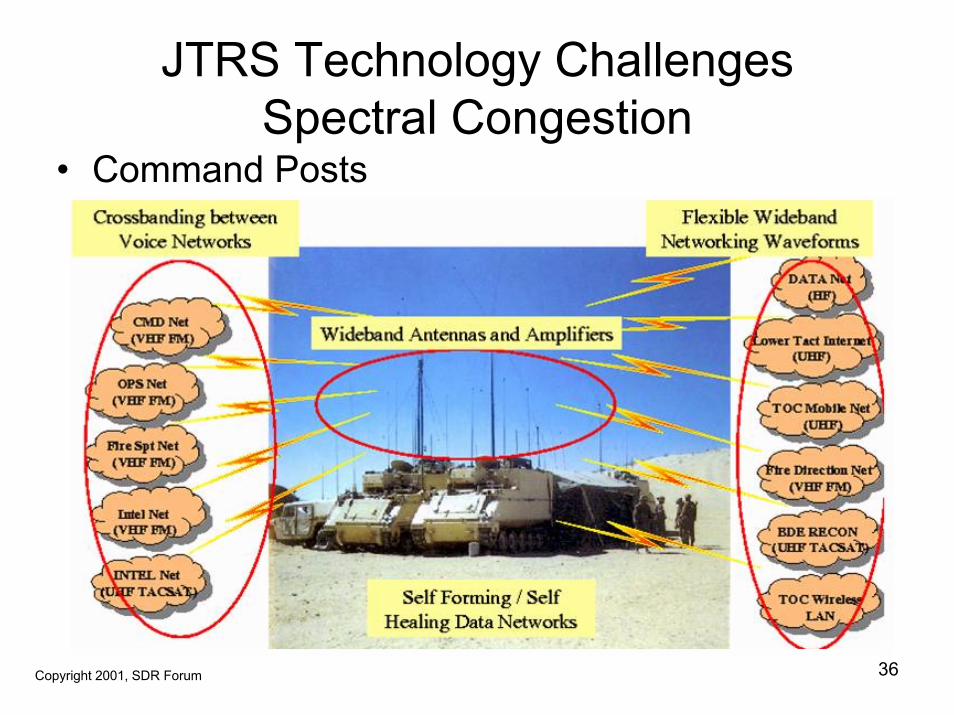
JTRS Technology ChallengesSpectral Congestion
• Command Posts
Copyright 2003, Space Coast Communication Systems, Inc. 36Copyright 2001, SDR Forum
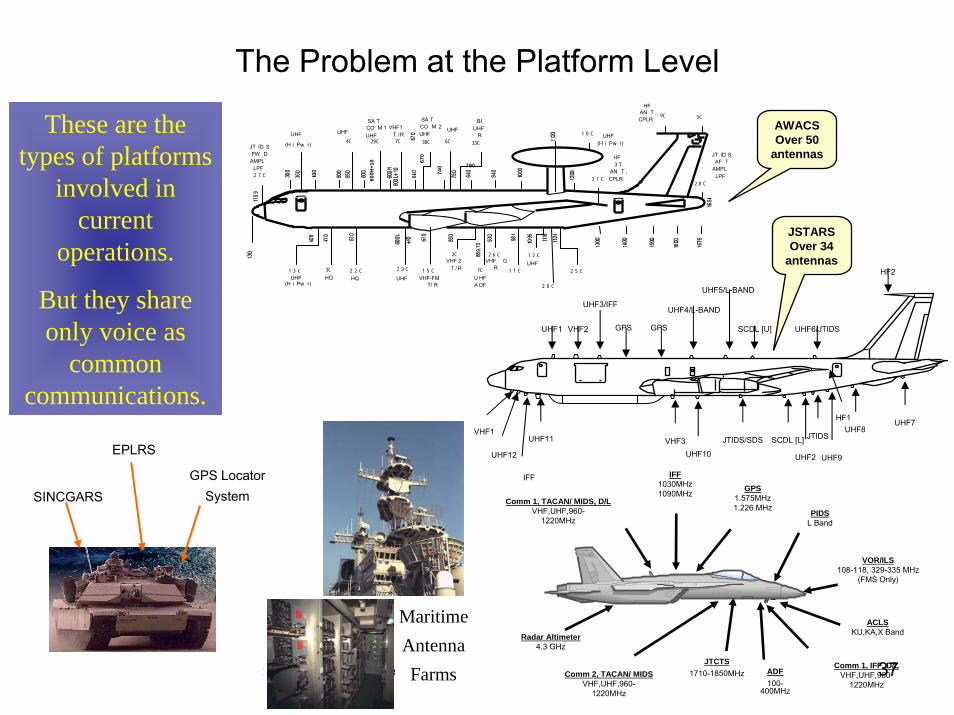
The Problem at the Platform Level
Copyright 2003, Space Coast Communication Systems, Inc. 37
EPLRS
GPS LocatorSystemSINCGARS
GPS1.575MHz1.226 MHz
Comm 1, TACAN/ MIDS, D/LVHF,UHF,960-
1220MHz
Radar Altimeter4.3 GHz
ACLSKU,KA,X Band
ADF100-
400MHz
JTCTS1710-1850MHz
IFF1030MHz1090MHz
PIDSL Band
Comm 2, TACAN/ MIDSVHF,UHF,960-
1220MHz
Comm 1, IFF, D/LVHF,UHF,960-
1220MHz
VOR/ILS108-118, 329-335 MHz
(FMS Only)
These are the types of platforms
involved in current
operations.
But they share only voice as
common communications.
UHF1 VHF2
UHF3/IFFUHF4/L-BAND
SCDL [U]
UHF5/L-BAND
GPS GPS UHF6/JTIDS
HF2
VHF1
HF1 UHF7UHF8
VHF3
UHF12
UHF11
UHF9
SCDL [L]JTIDS/SDS
UHF10
IFF
JTIDS
UHF2
MaritimeAntennaFarms
JSTARSOver 34
antennas
AWACSOver 50
antennas
2 0 C
4C 7C 6C
3C 1 5 C1 3 C 1C
2C 2 6 C
1 1 C
1 2 C
2 5 CUHF
(H i Pw r)HQ UHF VHF-FM
T/ R
VHF 2T / R
U HFA DF
VHF GR
UHF
HQ
UHF
(H i Pw r)
VHF1T /R UHF
(H i Pw r)
1 0 C
HF3 T
AN T ,CPLR2 1 C
9C
HFAN T ,CPLR 5C
2 8 C
JT ID SAF T
AMPLLPF2 7 C
SA TCO M 1UHF
JT ID SFW D
AMPLLPF
30C29C
2 2 C 2 3 C
UHF UHF
33C
790
BIUHF
R
600H
+10
SA TCO M 2UHF
670
740
Reconfigurable Devices
Copyright 2003, Space Coast Communication Systems, Inc. 38
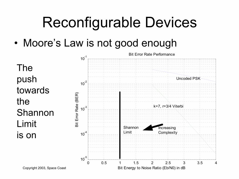
• Moore’s Law is not good enough
0 0.5 1 1.5 2 2.5 3 3.5 410-5
10-4
10-3
10-2
10-1Bit Error Rate Performance
Bit Energy to Noise Ratio (Eb/N0) in dB
Bit
Erro
r Rat
e (B
ER
)
ShannonLimit
Uncoded PSK
k=7, r=3/4 Viterbi
IncreasingComplexity
The push towards the Shannon Limitis on
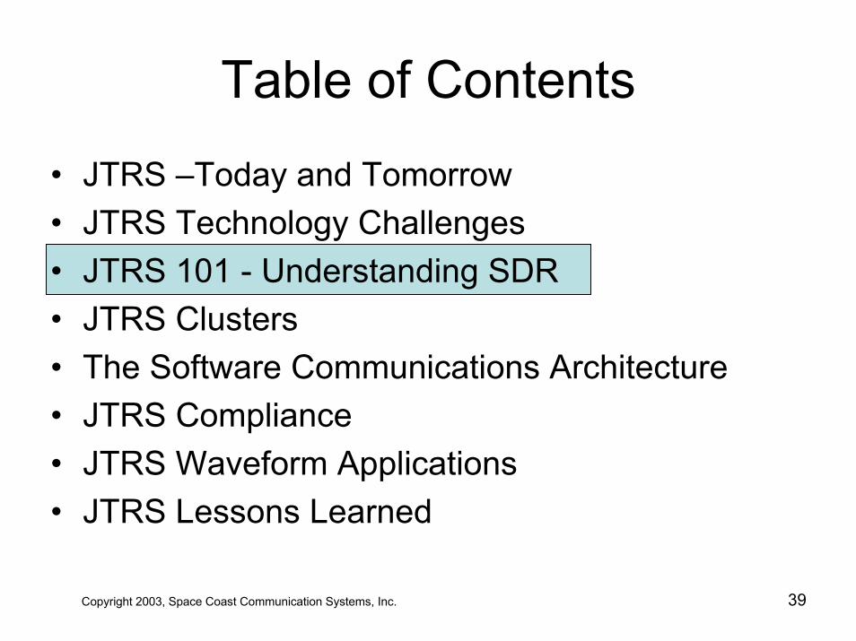
Table of Contents
• JTRS –Today and Tomorrow• JTRS Technology Challenges• JTRS 101 - Understanding SDR • JTRS Clusters• The Software Communications Architecture• JTRS Compliance• JTRS Waveform Applications • JTRS Lessons Learned
Copyright 2003, Space Coast Communication Systems, Inc. 39
Understanding SDR• SDR defined (by Joe Mitola)
– “A software radio is a radio whose channel modulation waveforms are defined in software. That is, waveforms are generated as sampled digital signals, converted from digital to analog via a wideband DAC and then possibly upconverted from IF to RF. The receiver, similarly, employs a wideband Analog to Digital Converter (ADC) that captures all of the channels of the software radio node. The receiver then extracts, downconverts and demodulates the channel waveform using software on a general purpose processor ”
Copyright 2003, Space Coast Communication Systems, Inc. 40
Understanding SDR
• SDR defined (by the FCC)– “47 C.F.R. 2.1 (c) Software defined radio. A
radio that includes a transmitter in which the operating parameters of frequency range, modulation type or maximum output power (either radiated or conducted) can be altered by making a change in software without making any changes to hardware components that affect the radio frequency emissions.”
Copyright 2003, Space Coast Communication Systems, Inc. 41
Understanding SDR
Copyright 2003, Space Coast Communication Systems, Inc. 42
• Emerging Architectures - Commercial– Sun Microsystems
• Java already used on NTT Docomo iMode phones– Intel
• “SDR in every die within 10 years”– Qualcomm
• BREW, Binary Runtime Environment for Wireless– GNU Radio (the Linux movement)
• GNU Radio allows the construction of radios where the actual waveforms transmitted and received are defined by software
Understanding SDR
Copyright 2003, Space Coast Communication Systems, Inc. 43
• Business Opportunities– Open Architecture mandated by JPO
• allows third-party development• productivity and development tools• new waveforms• upgrades• add-on applications
– SDR promotes technology insertion• innovative hardware upgrades easily installed• no modification to software• Moore’s law
Understanding SDREconomics
• Initial cost of entry high– High performance front ends– Large software infrastructure– Lots of computational horsepower– Not generally available on the open market
• IF implemented correctly …• Recurring AND operational costs lowered
– Don’t have to bring the ships into port – New applications on existing hardware
Copyright 2003, Space Coast Communication Systems, Inc. 44
Understanding SDR• Capability and Performance Incentives
– Interoperability• Typically implemented with redundant hardware• US inter-service not so bad• US and Allies huge problem space• Want “switchable” interoperability
– Spectral Usages• On demand commodity
– Waveform Portability• Waveform==Software increases portability
Copyright 2003, Space Coast Communication Systems, Inc. 45
Some Current DoD SDR Programs
• Technology Evolution 1996-present– Programmable Modular Communication
System (PMCS) This is what JTRS wascalled before it became JTRS
– Zebra Systems™– Joint Combat Information Terminal (JCIT)– Digital Modular Radio (DMR)
Copyright 2003, Space Coast Communication Systems, Inc. 46
Copyright 2003, Space Coast Communication Systems, Inc. 47
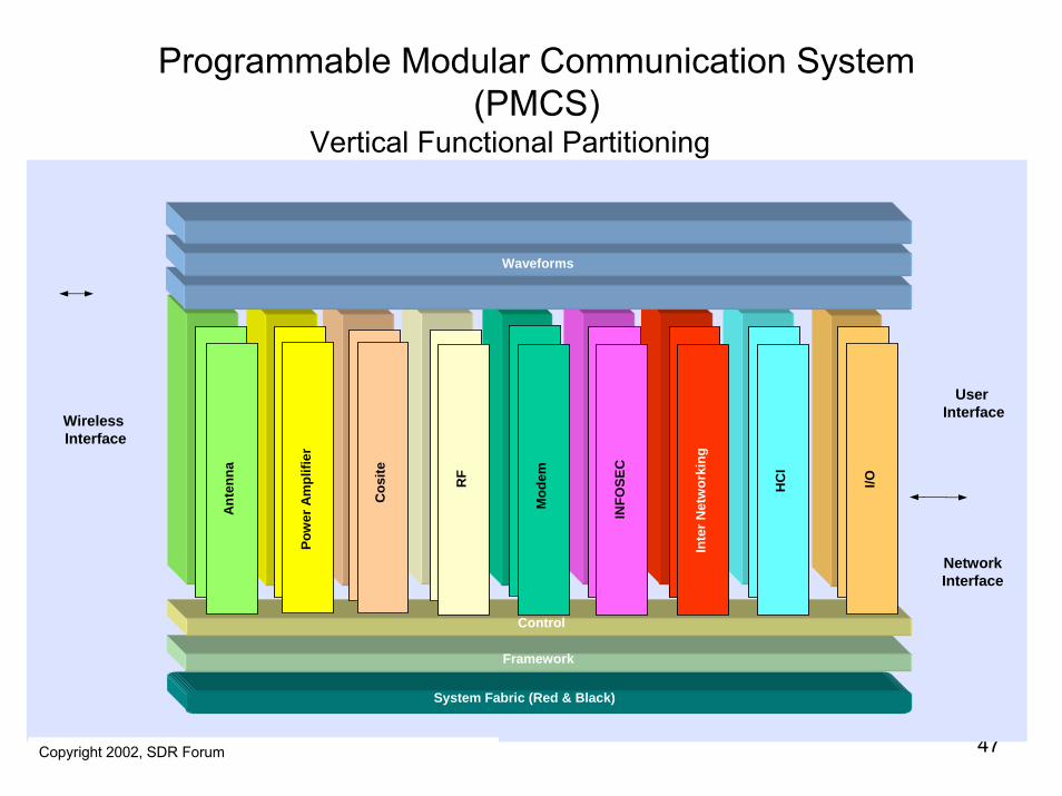
Programmable Modular Communication System(PMCS)
Vertical Functional Partitioning
UserInterface
Network Interface
System Fabric (Red & Black)
Framework
Control
Waveforms
Mod
em
INFO
SEC
Inte
r Net
wor
king
Cos
ite
Pow
er A
mpl
ifier
Ant
enna
RF
HC
I
I/O
WirelessInterface
Copyright 2002, SDR Forum
Current SDR DoD Programs• Zebra Systems ™• Multi-channel UHF SATCOM Transceiver• Architecture: PMCS / SDR Forum
– Programmable Modular Communication System
• First production units in late ’96• 2,4 and 8 channel versions• Waveforms
– TIBS, TRAP/TADIXS-B, SIDS, TADIL-A, OTCIXS• Multiple Embedded Crypto
– Railman, Hayfield, CDH
Copyright 2003, Space Coast Communication Systems, Inc. 48Zebra Systems is a Trademark of Mnemonics, Inc.
Copyright 2003, Space Coast Communication Systems, Inc. 49
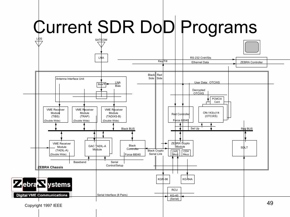
Current SDR DoD ProgramsLOS SATCOM
LNA
Bias T LNA Bias
Antenna Interface Unit
VME Receiver Module (TIBS)
VME Receiver Module (TRAP)
VME Receiver Module
(TADIXS-B)(Double Wide) (Double Wide) (Double Wide)
VME Receiver Module
(TADIL-A)(Double Wide)
GAC TADIL-A Module
Black Controller
Black BUS
Baseband Serial Control/Setup
Red BUSSet Up
Red Controller ON-143(v)14 (OTCIXS)
Decrypted OTCIXS
PCMCIA Card
User Data: OTCIXS
ZEBRA Controller
ZEBRA Crypto Module SDLT
Intf Mezz
CDH Mezz
KGR-96 KG-84A
RCU
KG-40 (Serial)
Black Side
Red Side
Key Fill Ethernet DataRS-232 Cntrl/Sts
�
Black Crypto Serial Link
Serial Interface (8 Pairs)
ZEBRA Chassis
Force 68040
Force 68040
Copyright 1997 IEEE
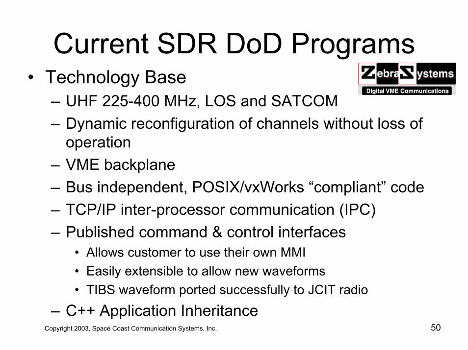
Current SDR DoD Programs• Technology Base
– UHF 225-400 MHz, LOS and SATCOM– Dynamic reconfiguration of channels without loss of
operation– VME backplane– Bus independent, POSIX/vxWorks “compliant” code – TCP/IP inter-processor communication (IPC)– Published command & control interfaces
• Allows customer to use their own MMI• Easily extensible to allow new waveforms• TIBS waveform ported successfully to JCIT radio
– C++ Application InheritanceCopyright 2003, Space Coast Communication Systems, Inc. 50
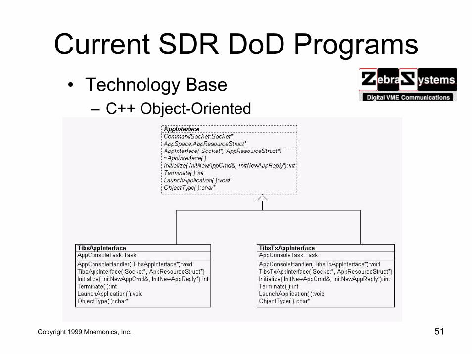
Current SDR DoD Programs
Copyright 2003, Space Coast Communication Systems, Inc. 51
• Technology Base– C++ Object-Oriented
Copyright 1999 Mnemonics, Inc.
Current SDR DoD Programs
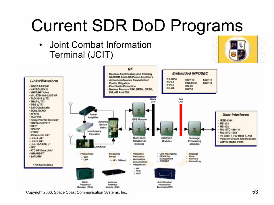
• Joint Combat Information Terminal (JCIT)– Naval Research Lab, 1995-present– Architecture: PMCS– 8 channel, 2 MHz to 512 MHz– CPUs: Lots and Lots of them– Form factor: SEM-E, IEEE 1394 backplane– Embedded INFOSEC, 14 algorithms– Waveforms:
• TRAP, TIBS, VHF ATC, SINCGARS
Copyright 2003, Space Coast Communication Systems, Inc. 52
Copyright 2003, Space Coast Communication Systems, Inc. 53
Current SDR DoD Programs• Joint Combat Information
Terminal (JCIT)
Current SDR DoD Programs
• Joint Combat Information Terminal (JCIT)– JCIT Application Queue Library (JAQL)– “C” library supports inter-processor communication
• jcom_send()• jcom_receive()• jcom_taskSpawn()• jcom_taskEnd()
– single header file “jcom.h” • visible in all compilation spaces• entire message catalog, array of structs indexed by #defines• automated tool synchronizes ICD and “jcom.h”
Copyright 2003, Space Coast Communication Systems, Inc. 54
Current SDR DoD Programs• Digital Modular Radio (DMR)
– Architecture: PMCS– First Demonstrated: June 1999– CPUs: G3 PPC’s, “n” proprietary single channel
modems with FPGA’s and dual ADSP 21060’s – Form factor: Compact PCI – INFOSEC: Advanced INFOSEC Module– Waveforms:
• MIL-STD 188-181 and 188-183 DAMA• Havequick, SINCGARS, Link 11 (partial)
Copyright 2003, Space Coast Communication Systems, Inc. 55
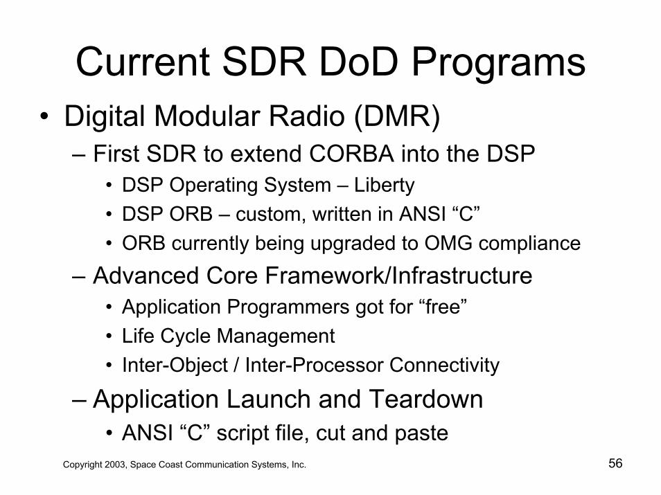
Current SDR DoD Programs• Digital Modular Radio (DMR)
– First SDR to extend CORBA into the DSP• DSP Operating System – Liberty• DSP ORB – custom, written in ANSI “C”• ORB currently being upgraded to OMG compliance
– Advanced Core Framework/Infrastructure• Application Programmers got for “free”• Life Cycle Management• Inter-Object / Inter-Processor Connectivity
– Application Launch and Teardown• ANSI “C” script file, cut and paste
Copyright 2003, Space Coast Communication Systems, Inc. 56
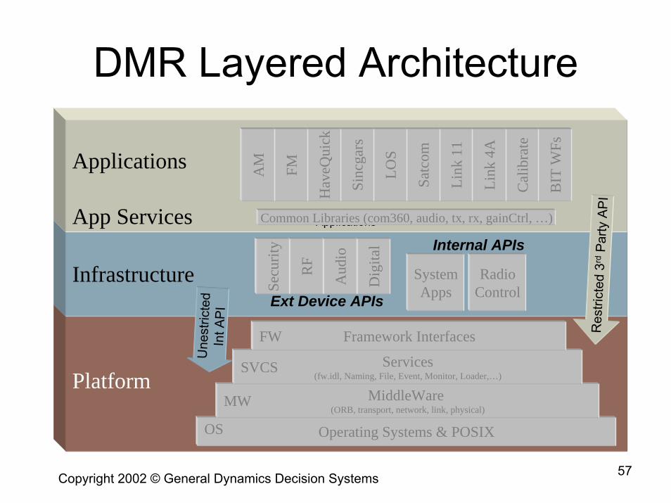
DMR Layered Architecture
Platform
ApplicationsCommon Libraries (com360, audio, tx, rx, gainCtrl, …)
Applications
Infrastructure
Platform
RadioControl
SystemApps
App Services
BIT
WFs
Internal APIs
Ext Device APIs
Res
trict
ed 3
rdPa
rty A
PI
Une
stric
ted
Int A
PI
Cal
ibra
te
Link
4A
Link
11
Satc
om
LOS
Sinc
gars
Hav
eQui
ck
FMAM
Dig
ital
Aud
io
RF
Secu
rity
Operating Systems & POSIX
MiddleWare (ORB, transport, network, link, physical)
Services(fw.idl, Naming, File, Event, Monitor, Loader,…)
Framework Interfaces
OS
MW
SVCS
FW
Copyright 2003, Space Coast Communication Systems, Inc. 57Copyright 2002 © General Dynamics Decision Systems
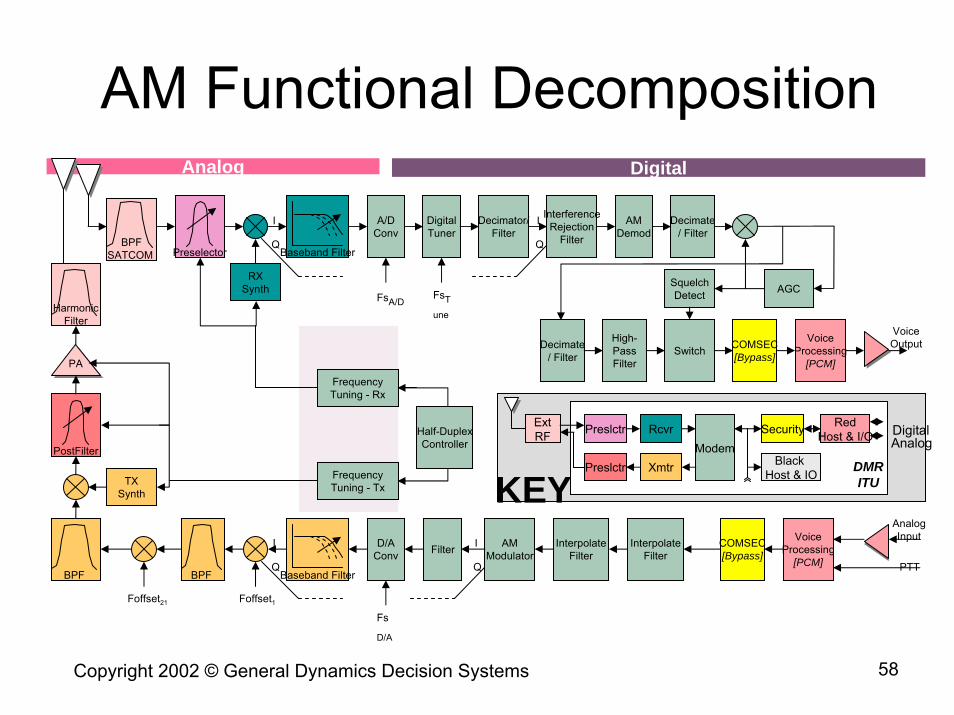
AM Functional DecompositionDigitalAnalog
Baseband Filter
A/DConv
DigitalTuner
Decimator/Filter
InterferenceRejection
Filter
AMDemod
Decimate/ Filter
Preselector
RXSynth
Baseband Filter
D/AConv Filter AM
ModulatorInterpolate
Filter
BPF
Foffset1Foffset21
BPF
PostFilter
TXSynth
PAPA
HarmonicFilter
FsA/D
Fs
D/A
FsTune
I
Q
I
Q
I
Q
I
Q
Decimate/ Filter Switch COMSEC
[Bypass]
COMSEC[Bypass]
VoiceProcessing
[PCM]
VoiceProcessing
[PCM]
AnalogInput
PTT
VoiceOutput
ExtRF Preslctr
Preslctr Xmtr
RcvrModem
Black Host & IO
Security RedHost & I/O Digital
Analog
DMRITUFrequency
Tuning - Tx
FrequencyTuning - Rx
AGCSquelchDetect
InterpolateFilter
High-PassFilter
Half-DuplexController
KEY
BPFSATCOM
Copyright 2003, Space Coast Communication Systems, Inc. 58Copyright 2002 © General Dynamics Decision Systems
Table of Contents
• JTRS –Today and Tomorrow• JTRS Technology Challenges• JTRS 101 - Understanding SDR • JTRS Clusters• The Software Communications Architecture• JTRS Compliance• JTRS Waveform Applications • JTRS Lessons Learned
Copyright 2003, Space Coast Communication Systems, Inc. 59
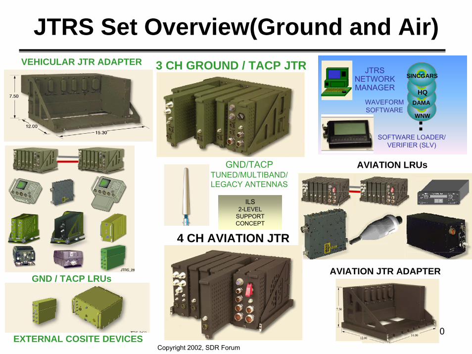
JTRS Set Overview(Ground and Air)
Copyright 2003, Space Coast Communication Systems, Inc. 60
3 CH GROUND / TACP JTR
EXTERNAL COSITE DEVICES
VEHICULAR JTR ADAPTER
4 CH AVIATION JTR
GND / TACP LRUs
GND/TACPTUNED/MULTIBAND/LEGACY ANTENNAS
AVIATION LRUs
AVIATION JTR ADAPTER
WAVEFORMSOFTWARE
SOFTWARE LOADER/VERIFIER (SLV)
WNW
DAMAHQ
SINCGARSJTRS
NETWORKMANAGER
ILS2-LEVEL
SUPPORT CONCEPT
Copyright 2002, SDR Forum
Copyright 2003, Space Coast Communication Systems, Inc. 61
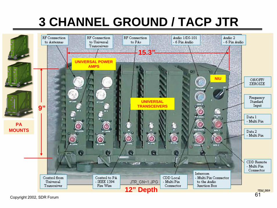
3 CHANNEL GROUND / TACP JTR
9”
15.3”
12” Depth
NIU
UNIVERSAL TRANSCEIVERS
UNIVERSAL POWER AMPS
PAMOUNTS
Copyright 2002, SDR Forum
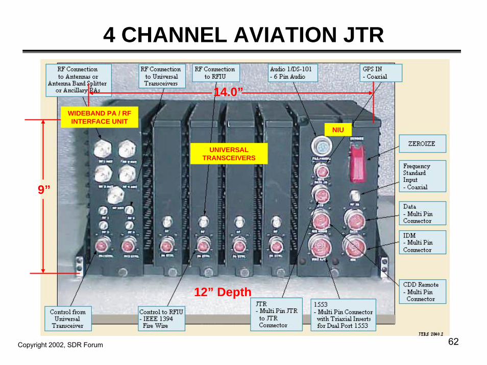
4 CHANNEL AVIATION JTR
Copyright 2003, Space Coast Communication Systems, Inc. 62
9”
14.0”
12” Depth
UNIVERSAL TRANSCEIVERS
NIU
WIDEBAND PA / RF INTERFACE UNIT
Copyright 2002, SDR Forum
Copyright 2003, Space Coast Communication Systems, Inc. 63
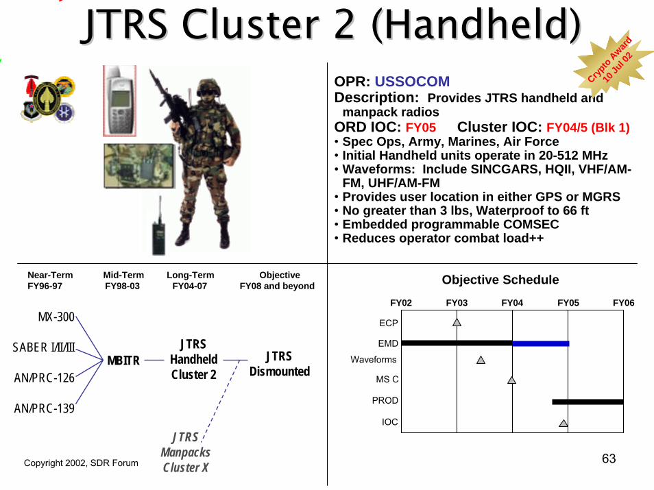
JTRS Cluster 2 (Handheld)JTRS Cluster 2 (Handheld)
FY06
ECP
EMD
MS C
PROD
IOC
FY02 FY03 FY04 FY05
Objective Schedule
Waveforms
OPR: USSOCOMDescription: Provides JTRS handheld and
manpack radiosORD IOC: FY05 Cluster IOC: FY04/5 (Blk 1)• Spec Ops, Army, Marines, Air Force• Initial Handheld units operate in 20-512 MHz• Waveforms: Include SINCGARS, HQII, VHF/AM-
FM, UHF/AM-FM• Provides user location in either GPS or MGRS• No greater than 3 lbs, Waterproof to 66 ft• Embedded programmable COMSEC• Reduces operator combat load++
Copyright 2002, SDR Forum
MX-300
SABER I/II/III
AN/PRC-126
AN/PRC-139
Near-Term Mid-Term Long-Term ObjectiveFY96-97 FY98-03 FY04-07 FY08 and beyond
MBITRJTRS
HandheldCluster 2
JTRSDismounted
JTRSManpacksCluster X
Crypto A
ward
Crypto A
ward
10 Ju
l 02
10 Ju
l 02
JTRS Cluster 3 (Maritime/FixedJTRS Cluster 3 (Maritime/Fixed--site)site)
Copyright 2003, Space Coast Communication Systems, Inc. 64
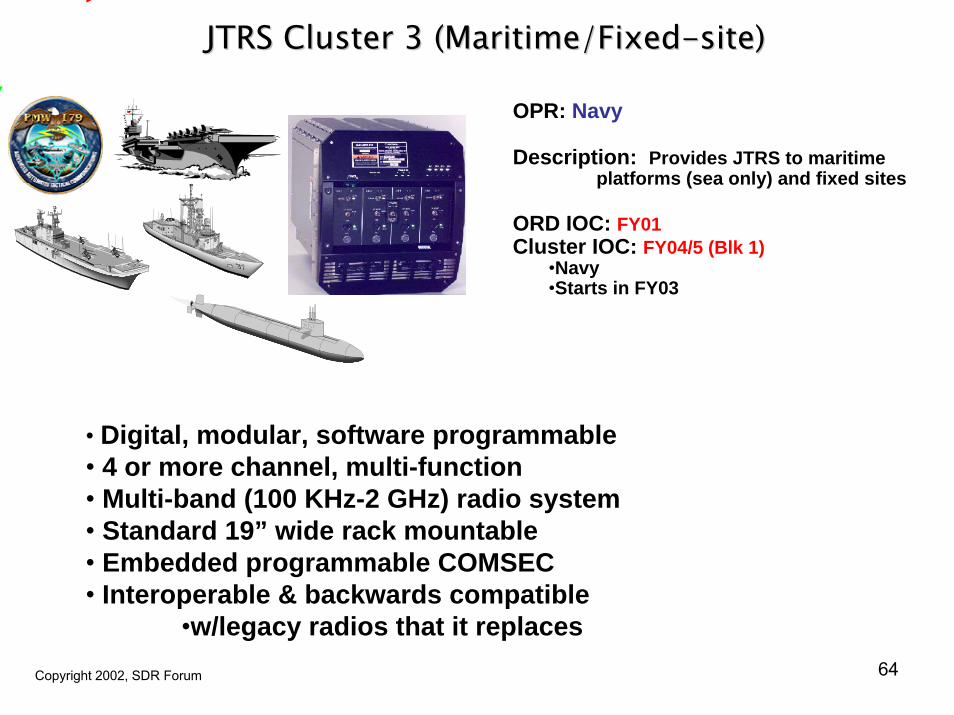
OPR: Navy
Description: Provides JTRS to maritime platforms (sea only) and fixed sites
ORD IOC: FY01Cluster IOC: FY04/5 (Blk 1)
•Navy•Starts in FY03
• Digital, modular, software programmable • 4 or more channel, multi-function• Multi-band (100 KHz-2 GHz) radio system• Standard 19” wide rack mountable• Embedded programmable COMSEC• Interoperable & backwards compatible
•w/legacy radios that it replacesCopyright 2002, SDR Forum
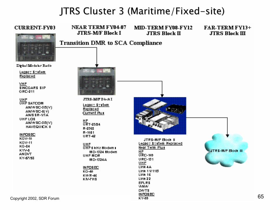
JTRS Cluster 3 (Maritime/FixedJTRS Cluster 3 (Maritime/Fixed--site)site)
Copyright 2003, Space Coast Communication Systems, Inc. 65Copyright 2002, SDR Forum
JTRS Cluster 4 (Airborne)JTRS Cluster 4 (Airborne)
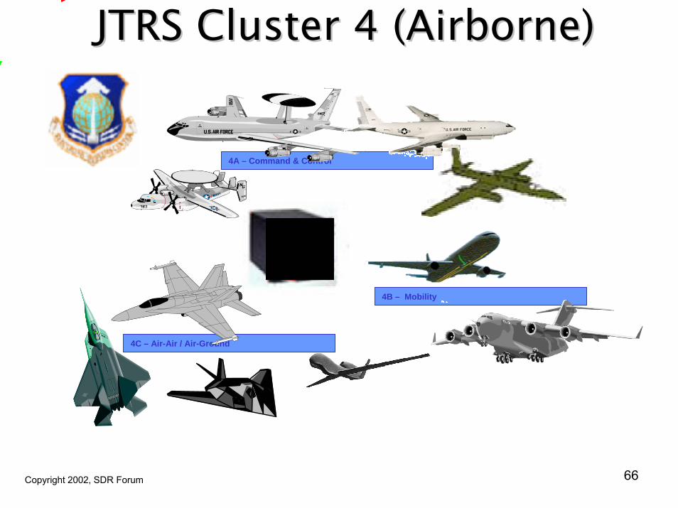
4C – Air-Air / Air-Ground
4A – Command & Control
4B – Mobility
Copyright 2003, Space Coast Communication Systems, Inc. 66Copyright 2002, SDR Forum
JTRS Cluster 4 (Airborne)JTRS Cluster 4 (Airborne)
Copyright 2003, Space Coast Communication Systems, Inc. 67Copyright 2002, SDR Forum
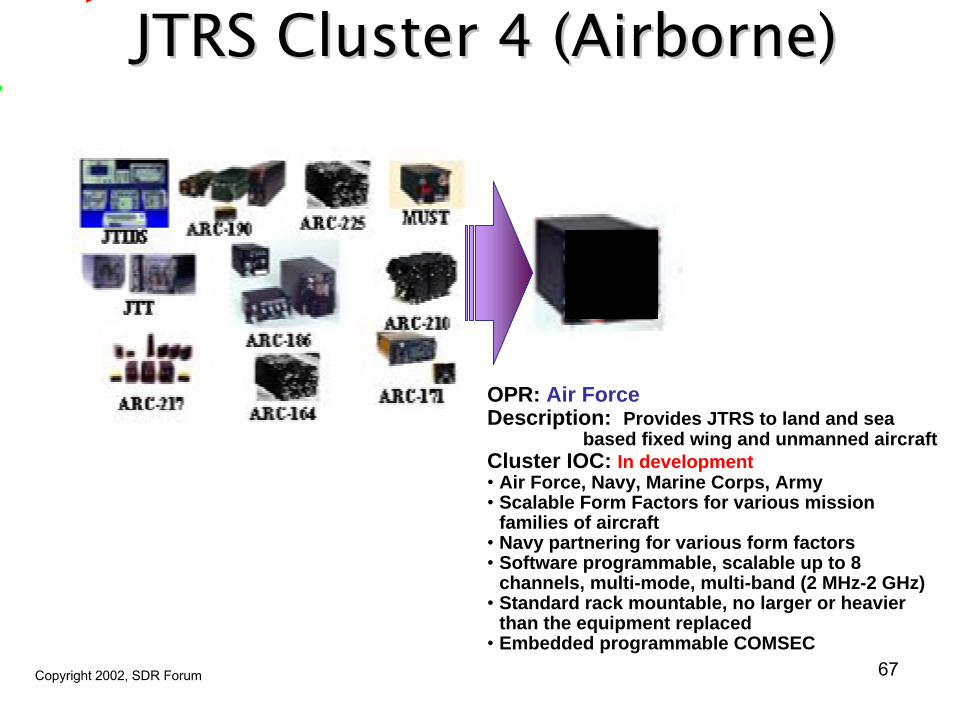
OPR: Air ForceDescription: Provides JTRS to land and sea
based fixed wing and unmanned aircraftCluster IOC: In development• Air Force, Navy, Marine Corps, Army• Scalable Form Factors for various mission
families of aircraft• Navy partnering for various form factors• Software programmable, scalable up to 8
channels, multi-mode, multi-band (2 MHz-2 GHz)• Standard rack mountable, no larger or heavier
than the equipment replaced• Embedded programmable COMSEC
Copyright 2003, Space Coast Communication Systems, Inc. 68Cry
pto
Obj
Non
-Cl1
CL
1 N
on-C
ore
Clu
ster
1 C
ore
Cry
pto
Cry
pto
Obj
Obj
NonNon
-- ClCl 1
CL
1 N
on1
CL
1 N
on-- C
ore
Clu
ster
1 C
ore
Cor
e
C
lust
er 1
Cor
e
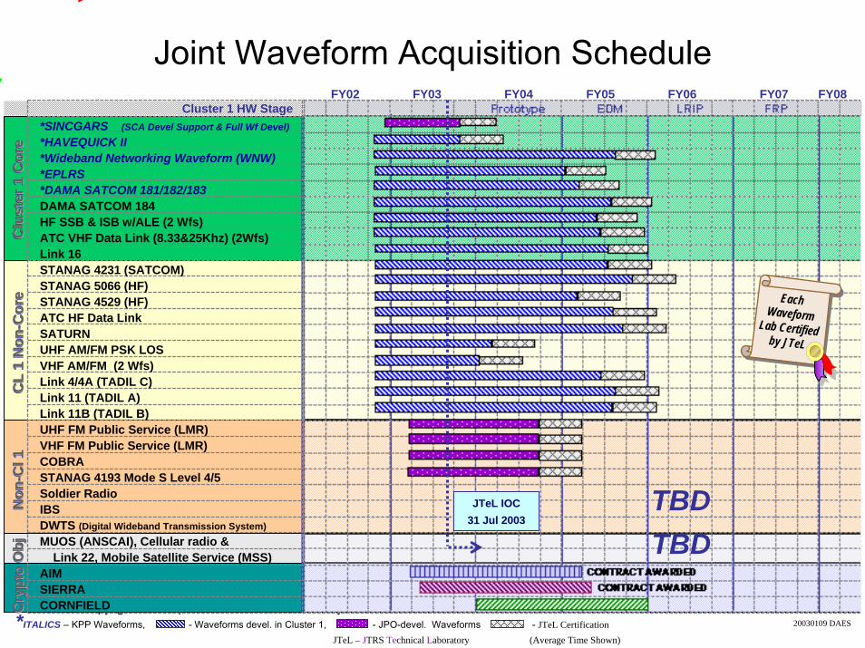
*SINCGARS (SCA Devel Support & Full Wf Devel)*HAVEQUICK II*Wideband Networking Waveform (WNW)*EPLRS*DAMA SATCOM 181/182/183DAMA SATCOM 184HF SSB & ISB w/ALE (2 Wfs)ATC VHF Data Link (8.33&25Khz) (2Wfs)Link 16STANAG 4231 (SATCOM)STANAG 5066 (HF)STANAG 4529 (HF)ATC HF Data LinkSATURNUHF AM/FM PSK LOSVHF AM/FM (2 Wfs)Link 4/4A (TADIL C)Link 11 (TADIL A)Link 11B (TADIL B)UHF FM Public Service (LMR)VHF FM Public Service (LMR)COBRASTANAG 4193 Mode S Level 4/5Soldier RadioIBSDWTS (Digital Wideband Transmission System)MUOS (ANSCAI), Cellular radio &
Link 22, Mobile Satellite Service (MSS)AIMSIERRACORNFIELD
FY02 FY03 FY04 FY05 FY06 FY07 FY08Cluster 1 HW Stage Prototype EDM LRIP FRP
*ITALICS – KPP Waveforms, - Waveforms devel. in Cluster 1, - JPO-devel. Waveforms - JTeL CertificationJTeL – JTRS Technical Laboratory (Average Time Shown)
Joint Waveform Acquisition Schedule
EachWaveform
Lab Certified by JTeL
TBDTBD
20030109 DAES
JTeL IOC31 Jul 2003
Table of Contents
• JTRS –Today and Tomorrow• JTRS Technology Challenges• JTRS 101 - Understanding SDR • JTRS Clusters• The Software Communications Architecture• JTRS Compliance• JTRS Waveform Applications • JTRS Lessons Learned
Copyright 2003, Space Coast Communication Systems, Inc. 69
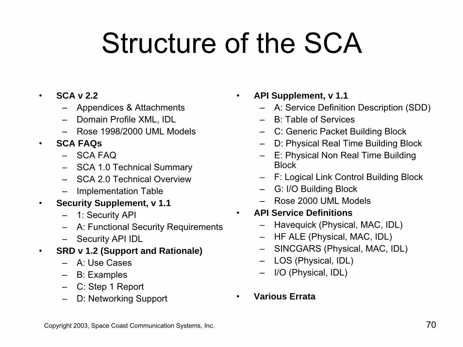
Structure of the SCA• SCA v 2.2
– Appendices & Attachments– Domain Profile XML, IDL– Rose 1998/2000 UML Models
• SCA FAQs– SCA FAQ– SCA 1.0 Technical Summary– SCA 2.0 Technical Overview– Implementation Table
• Security Supplement, v 1.1– 1: Security API– A: Functional Security Requirements– Security API IDL
• SRD v 1.2 (Support and Rationale)– A: Use Cases– B: Examples– C: Step 1 Report– D: Networking Support
• API Supplement, v 1.1– A: Service Definition Description (SDD)– B: Table of Services– C: Generic Packet Building Block– D: Physical Real Time Building Block– E: Physical Non Real Time Building
Block– F: Logical Link Control Building Block– G: I/O Building Block– Rose 2000 UML Models
• API Service Definitions– Havequick (Physical, MAC, IDL)– HF ALE (Physical, MAC, IDL)– SINCGARS (Physical, MAC, IDL)– LOS (Physical, IDL)– I/O (Physical, IDL)
• Various Errata
Copyright 2003, Space Coast Communication Systems, Inc. 70
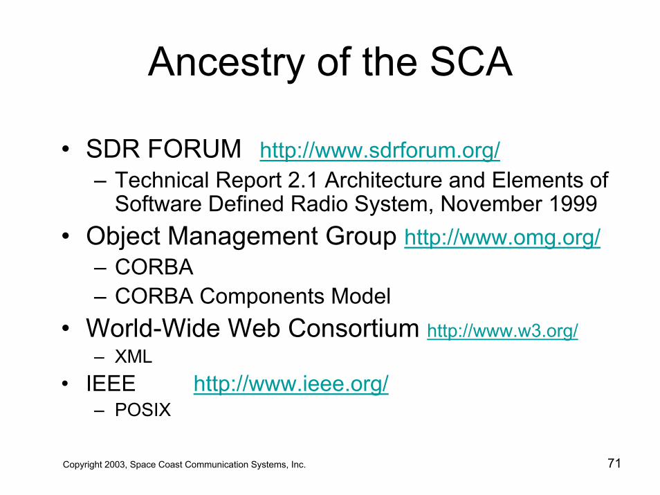
Ancestry of the SCA
• SDR FORUM http://www.sdrforum.org/– Technical Report 2.1 Architecture and Elements of
Software Defined Radio System, November 1999• Object Management Group http://www.omg.org/
– CORBA– CORBA Components Model
• World-Wide Web Consortium http://www.w3.org/– XML
• IEEE http://www.ieee.org/– POSIX
Copyright 2003, Space Coast Communication Systems, Inc. 71
Structure of the SCA
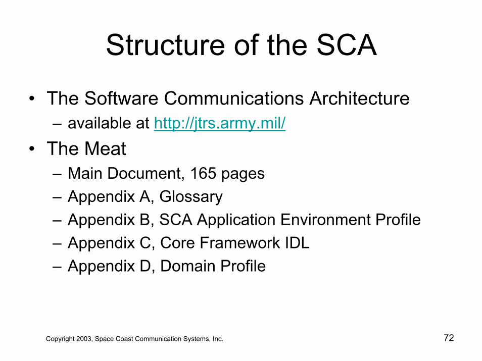
• The Software Communications Architecture– available at http://jtrs.army.mil/
• The Meat– Main Document, 165 pages– Appendix A, Glossary– Appendix B, SCA Application Environment Profile– Appendix C, Core Framework IDL– Appendix D, Domain Profile
Copyright 2003, Space Coast Communication Systems, Inc. 72
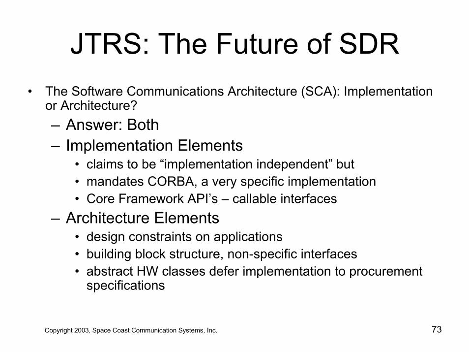
JTRS: The Future of SDR• The Software Communications Architecture (SCA): Implementation
or Architecture?– Answer: Both– Implementation Elements
• claims to be “implementation independent” but • mandates CORBA, a very specific implementation• Core Framework API’s – callable interfaces
– Architecture Elements• design constraints on applications• building block structure, non-specific interfaces• abstract HW classes defer implementation to procurement
specifications
Copyright 2003, Space Coast Communication Systems, Inc. 73
Structure of the SCA
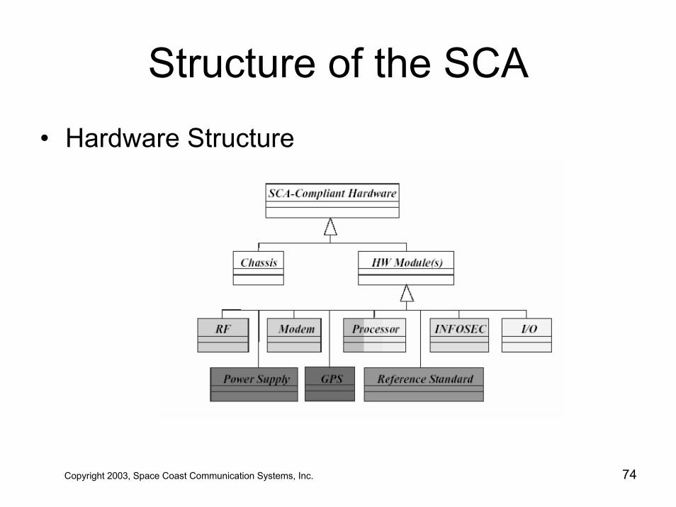
• Hardware Structure
Copyright 2003, Space Coast Communication Systems, Inc. 74
Core Framework (CF)Commercial Off-the-Shelf (COTS)
Non-Core (Radio) Applications
OE
Red (Non-Secure) Hardware Bus
CFServices &
Applications
CORBA ORB &Services
(Middleware)
Network Stacks & Serial Interface Services
Board Support Package (Bus Layer)
POSIX Operating System
RF API
RF API
Black (Secure) Hardware Bus
CFServices &
Applications
CORBA ORB &Services
(Middleware)
Network Stacks & Serial Interface Services
Board Support Package (Bus Layer)
POSIX Operating System
Core Framework IDL (“Logical Software Bus” via CORBA)
Non-CORBAModem
ApplicationsNon-CORBAModem API
Non-CORBASecurity
Applications
Non-CORBAHost
ApplicationsNon-CORBASecurity APIRF
ModemApplications
Link, NetworkApplications
SecurityApplications
ModemAdapter
SecurityAdapter
SecurityAdapter
HostAdapter
HostApplications
Modem NAPI Link, Network NAPI Link, Network NAPI
Non-CORBAHost API
Link, NetworkApplications
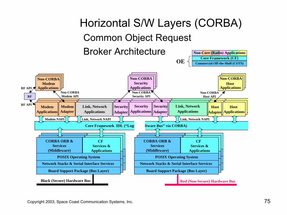
Horizontal S/W Layers (CORBA)Common Object Request Broker Architecture
Copyright 2003, Space Coast Communication Systems, Inc. 75
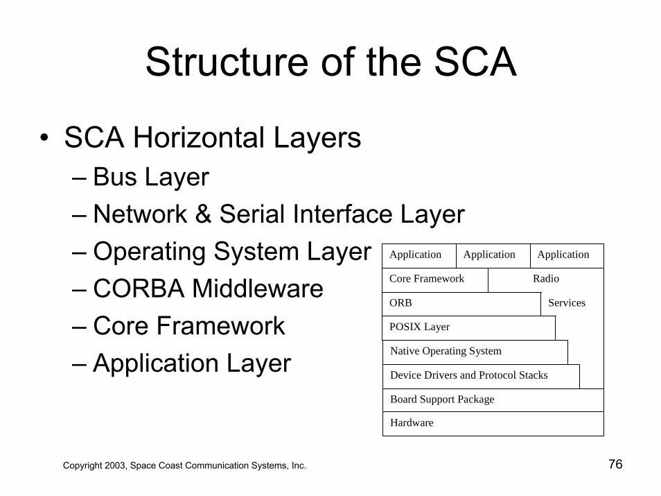
Structure of the SCA
• SCA Horizontal Layers– Bus Layer– Network & Serial Interface Layer– Operating System Layer– CORBA Middleware– Core Framework– Application Layer
Application Application
Core Framework
ORB
Radio
POSIX Layer
Native Operating System
Device Drivers and Protocol Stacks
Board Support Package
Hardware
Services
Application
Copyright 2003, Space Coast Communication Systems, Inc. 76
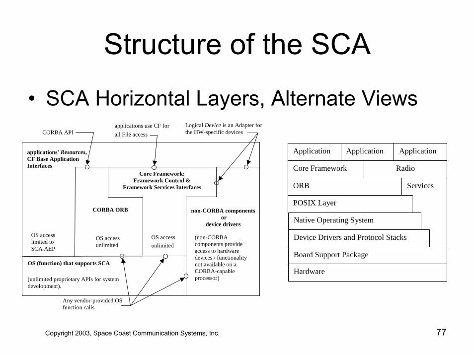
Structure of the SCA
• SCA Horizontal Layers, Alternate ViewsLogical Device is an Adapter forthe HW-specific devices
non-CORBA components or
device drivers
Core Framework:Framework Control &
Framework Services Interfaces
applications' Resources,CF Base ApplicationInterfaces
CORBA ORB
applications use CF forall File accessCORBA API
OS accesslimited toSCA AEP
OS accessunlimited
OS accessunlimited
OS (function) that supports SCA
(unlimited proprietary APIs for systemdevelopment).
Any vendor-provided OSfunction calls
(non-CORBAcomponents provideaccess to hardwaredevices / functionalitynot available on aCORBA-capableprocessor)
Application Application
Core Framework
ORB
Radio
POSIX Layer
Native Operating System
Device Drivers and Protocol Stacks
Board Support Package
Hardware
Services
Application
Copyright 2003, Space Coast Communication Systems, Inc. 77
Layers of the SCA
• The Bus Layer– Board Support Package
• Hardware Abstraction Layer (HAL)• Layer between Hardware and OS• Allows OS to port easily from board-to-board• Device Drivers offer uniform interface to OS• Homogenizes backplane differences• Unifies memory map• Usually offered by board vendor• Want to avoid using atypical features
Copyright 2003, Space Coast Communication Systems, Inc. 78
Structure of the SCA
• The SCA Networking Layer– SCA builds on commercial networking
protocols– Low level protocol stacks provide reliable
transport over Bus Layer– TCP/IP or 1394 might run over backplane– PPP, SLIP run over serial bus– CORBA can bypass the OS and directly
access these commercial layersCopyright 2003, Space Coast Communication Systems, Inc. 79
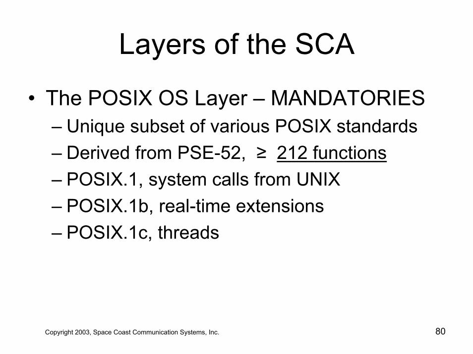
Layers of the SCA
• The POSIX OS Layer – MANDATORIES– Unique subset of various POSIX standards– Derived from PSE-52, ≥ 212 functions– POSIX.1, system calls from UNIX– POSIX.1b, real-time extensions– POSIX.1c, threads
Copyright 2003, Space Coast Communication Systems, Inc. 80
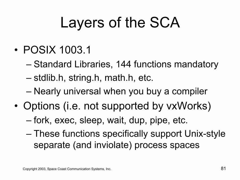
Layers of the SCA
• POSIX 1003.1– Standard Libraries, 144 functions mandatory – stdlib.h, string.h, math.h, etc.– Nearly universal when you buy a compiler
• Options (i.e. not supported by vxWorks)– fork, exec, sleep, wait, dup, pipe, etc.– These functions specifically support Unix-style
separate (and inviolate) process spaces
Copyright 2003, Space Coast Communication Systems, Inc. 81
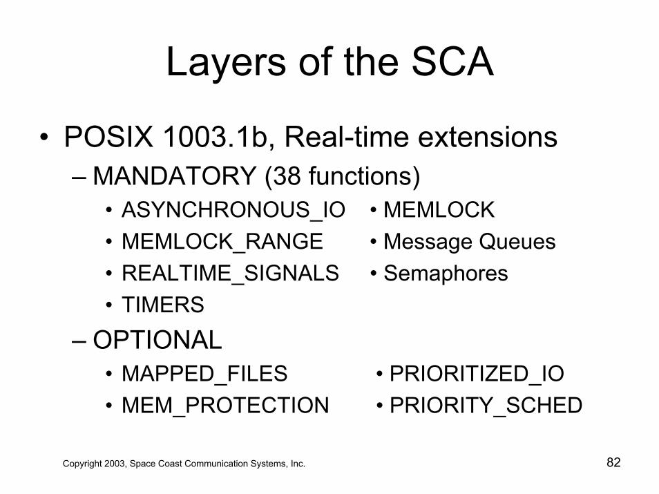
Layers of the SCA
• POSIX 1003.1b, Real-time extensions– MANDATORY (38 functions)
• ASYNCHRONOUS_IO • MEMLOCK• MEMLOCK_RANGE • Message Queues• REALTIME_SIGNALS • Semaphores• TIMERS
– OPTIONAL• MAPPED_FILES • PRIORITIZED_IO• MEM_PROTECTION • PRIORITY_SCHED
Copyright 2003, Space Coast Communication Systems, Inc. 82
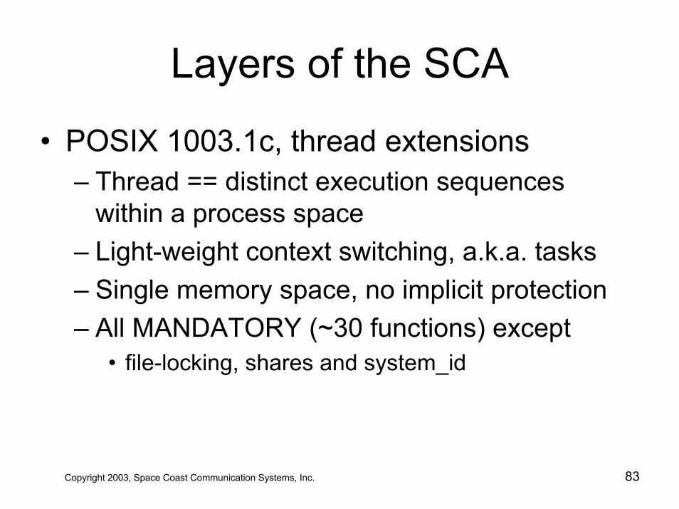
Layers of the SCA
• POSIX 1003.1c, thread extensions– Thread == distinct execution sequences
within a process space– Light-weight context switching, a.k.a. tasks– Single memory space, no implicit protection– All MANDATORY (~30 functions) except
• file-locking, shares and system_id
Copyright 2003, Space Coast Communication Systems, Inc. 83
SCA Middleware
• … shall use middleware that provides …– orbos/98-05-13, minimumCORBACommonObjectRequestBrokerArchitecturehttp://www.omg.org/cgi-bin/doc?orbos/98-05-13
Copyright 2003, Space Coast Communication Systems, Inc. 84
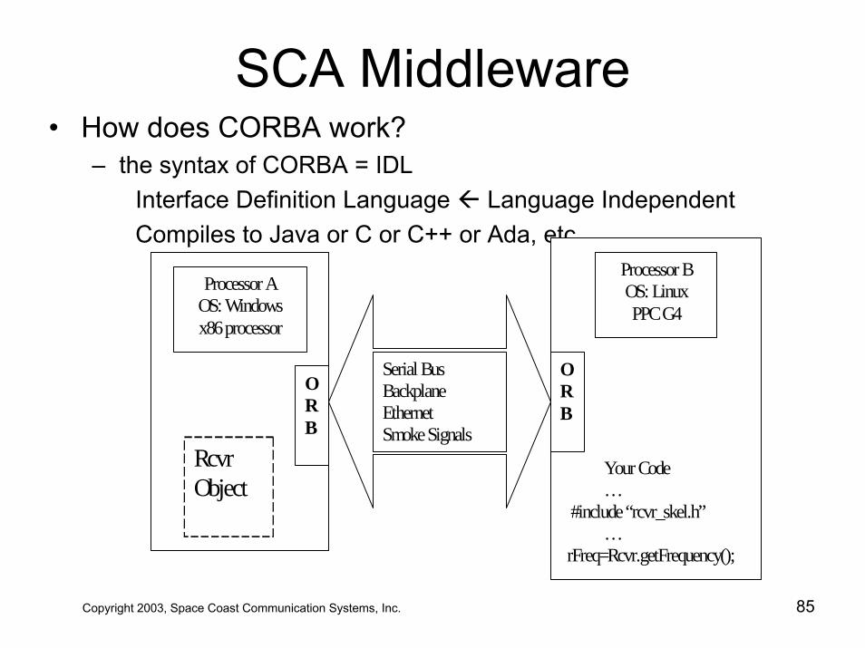
SCA Middleware• How does CORBA work?
– the syntax of CORBA = IDLInterface Definition Language Language IndependentCompiles to Java or C or C++ or Ada, etc.
Processor A OS: Windows x86 processor
Processor B OS: Linux PPC G4
Serial Bus Backplane Ethernet Smoke Signals
Your Code … #include “rcvr_skel.h” … rFreq=Rcvr.getFrequency();
Rcvr Object
ORB
ORB
Copyright 2003, Space Coast Communication Systems, Inc. 85
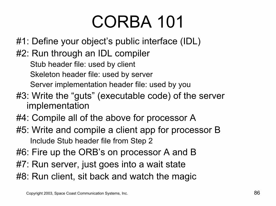
CORBA 101#1: Define your object’s public interface (IDL)#2: Run through an IDL compiler
Stub header file: used by clientSkeleton header file: used by serverServer implementation header file: used by you
#3: Write the “guts” (executable code) of the server implementation
#4: Compile all of the above for processor A#5: Write and compile a client app for processor B
Include Stub header file from Step 2#6: Fire up the ORB’s on processor A and B#7: Run server, just goes into a wait state#8: Run client, sit back and watch the magic
Copyright 2003, Space Coast Communication Systems, Inc. 86
SCA Middleware Services
• CORBA Naming Service shall …– shall support CosNaming CORBA module &
NamingContext operations …– formal/00-11-01– optional in SCA v2.1– MANDATORY in SCA v2.2
http://www.omg.org/cgi-bin/doc?formal/00-11-01
Copyright 2003, Space Coast Communication Systems, Inc. 87
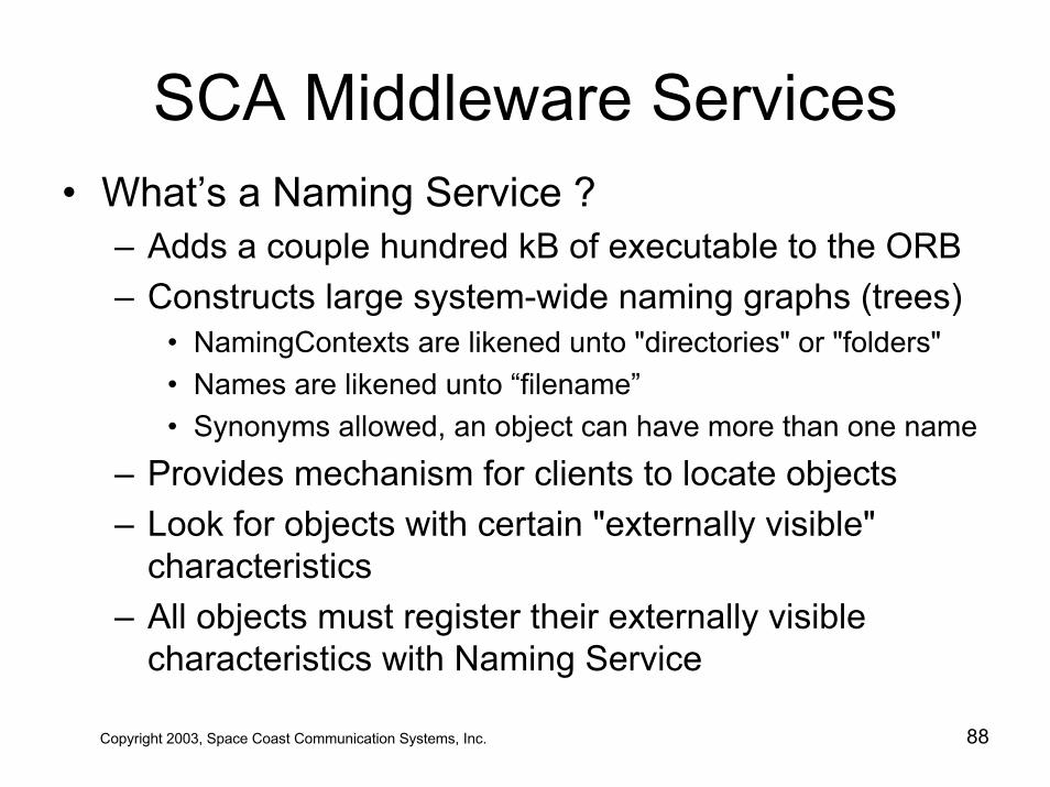
SCA Middleware Services• What’s a Naming Service ?
– Adds a couple hundred kB of executable to the ORB– Constructs large system-wide naming graphs (trees)
• NamingContexts are likened unto "directories" or "folders"• Names are likened unto “filename”• Synonyms allowed, an object can have more than one name
– Provides mechanism for clients to locate objects – Look for objects with certain "externally visible"
characteristics– All objects must register their externally visible
characteristics with Naming Service
Copyright 2003, Space Coast Communication Systems, Inc. 88
SCA Middleware Services
• CORBA Event Service shall …– shall support Push interfaces …– formal/01-03-01– not mentioned in SCA v2.1– MANDATORY in SCA v2.2
http://www.omg.org/cgi-bin/doc?formal/01-03-01
Copyright 2003, Space Coast Communication Systems, Inc. 89
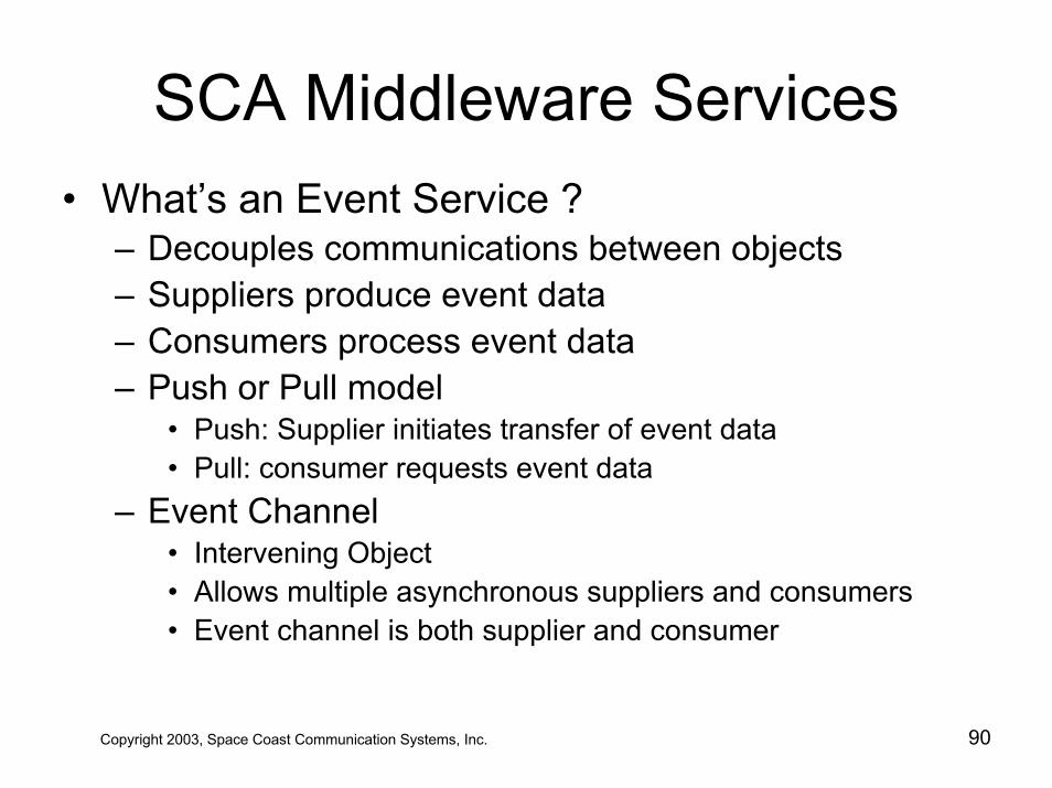
SCA Middleware Services• What’s an Event Service ?
– Decouples communications between objects– Suppliers produce event data– Consumers process event data– Push or Pull model
• Push: Supplier initiates transfer of event data• Pull: consumer requests event data
– Event Channel• Intervening Object• Allows multiple asynchronous suppliers and consumers• Event channel is both supplier and consumer
Copyright 2003, Space Coast Communication Systems, Inc. 90
What is an SCA Core Framework?
• Set of CORBA objects that provide …– deployment– management– interconnection– intercommunication
of software application components
Copyright 2003, Space Coast Communication Systems, Inc. 91
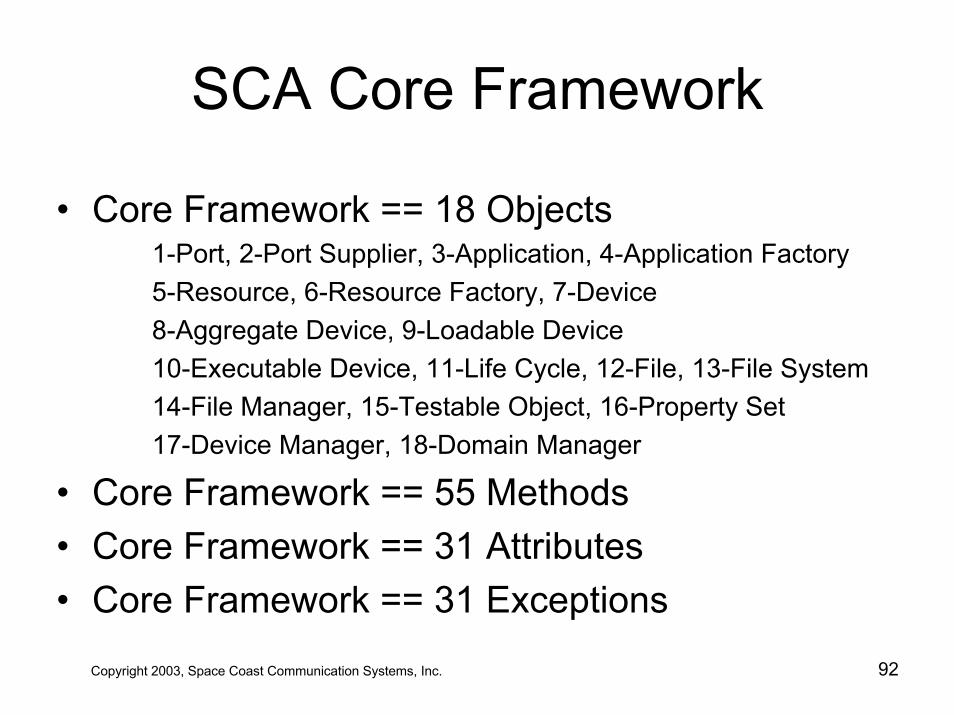
SCA Core Framework
• Core Framework == 18 Objects1-Port, 2-Port Supplier, 3-Application, 4-Application Factory5-Resource, 6-Resource Factory, 7-Device8-Aggregate Device, 9-Loadable Device10-Executable Device, 11-Life Cycle, 12-File, 13-File System14-File Manager, 15-Testable Object, 16-Property Set17-Device Manager, 18-Domain Manager
• Core Framework == 55 Methods• Core Framework == 31 Attributes• Core Framework == 31 Exceptions
Copyright 2003, Space Coast Communication Systems, Inc. 92
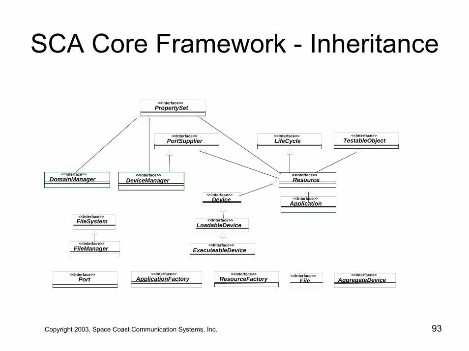
SCA Core Framework - Inheritance
<<Interface>>PortSupplier
<<Interface>>Device
<<Interface>>DomainManager
<<Interface>>DeviceManager
<<Interface>>FileManager
<<Interface>>FileSystem <<Interface>>
LoadableDevice
<<Interface>>ExecuteableDevice
<<Interface>>PropertySet
<<Interface>>Application
<<Interface>>Resource
<<Interface>>LifeCycle
<<Interface>>TestableObject
<<Interface>>Port
<<Interface>>ApplicationFactory
<<Interface>>ResourceFactory <<Interface>>
File<<Interface>>
AggregateDevice
Copyright 2003, Space Coast Communication Systems, Inc. 93
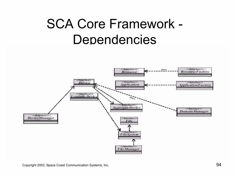
SCA Core Framework -Dependencies
Copyright 2003, Space Coast Communication Systems, Inc. 94
Copyright 2003, Space Coast Communication Systems, Inc. 95
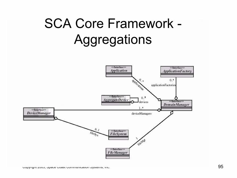
SCA Core Framework -Aggregations
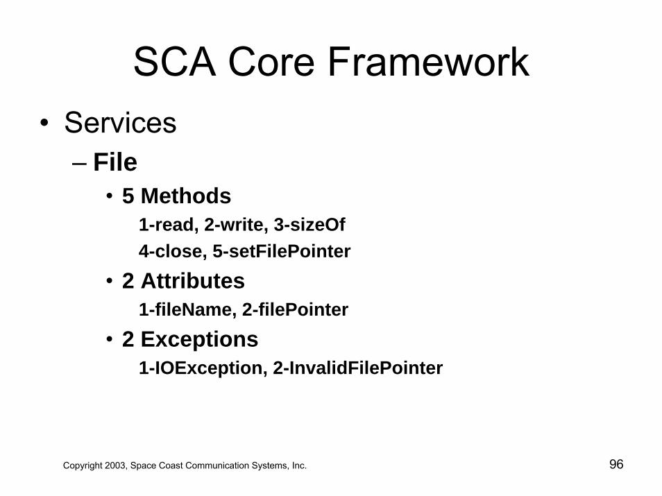
SCA Core Framework• Services
– File• 5 Methods
1-read, 2-write, 3-sizeOf4-close, 5-setFilePointer
• 2 Attributes1-fileName, 2-filePointer
• 2 Exceptions1-IOException, 2-InvalidFilePointer
Copyright 2003, Space Coast Communication Systems, Inc. 96
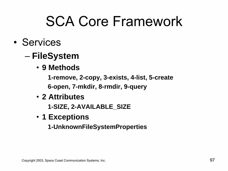
SCA Core Framework• Services
– FileSystem• 9 Methods
1-remove, 2-copy, 3-exists, 4-list, 5-create6-open, 7-mkdir, 8-rmdir, 9-query
• 2 Attributes1-SIZE, 2-AVAILABLE_SIZE
• 1 Exceptions1-UnknownFileSystemProperties
Copyright 2003, Space Coast Communication Systems, Inc. 97
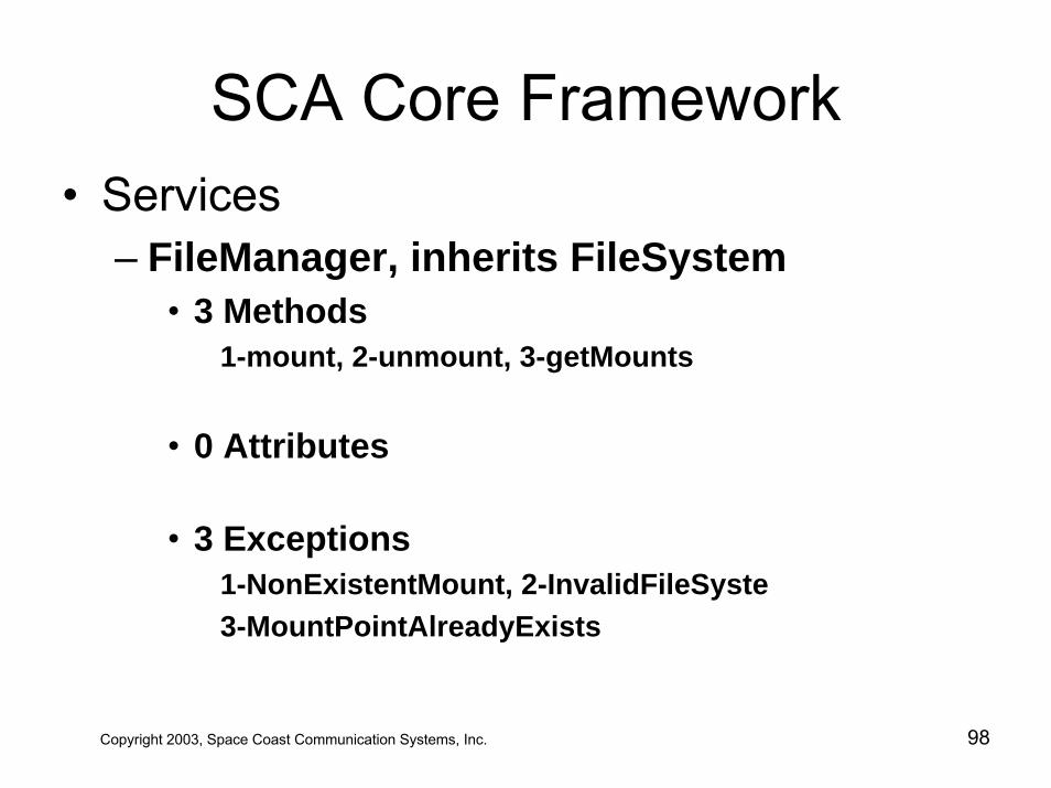
SCA Core Framework• Services
– FileManager, inherits FileSystem• 3 Methods
1-mount, 2-unmount, 3-getMounts
• 0 Attributes
• 3 Exceptions1-NonExistentMount, 2-InvalidFileSyste3-MountPointAlreadyExists
Copyright 2003, Space Coast Communication Systems, Inc. 98
SCA Core Framework
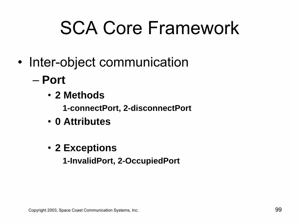
• Inter-object communication – Port
• 2 Methods1-connectPort, 2-disconnectPort
• 0 Attributes
• 2 Exceptions1-InvalidPort, 2-OccupiedPort
Copyright 2003, Space Coast Communication Systems, Inc. 99
SCA Core Framework
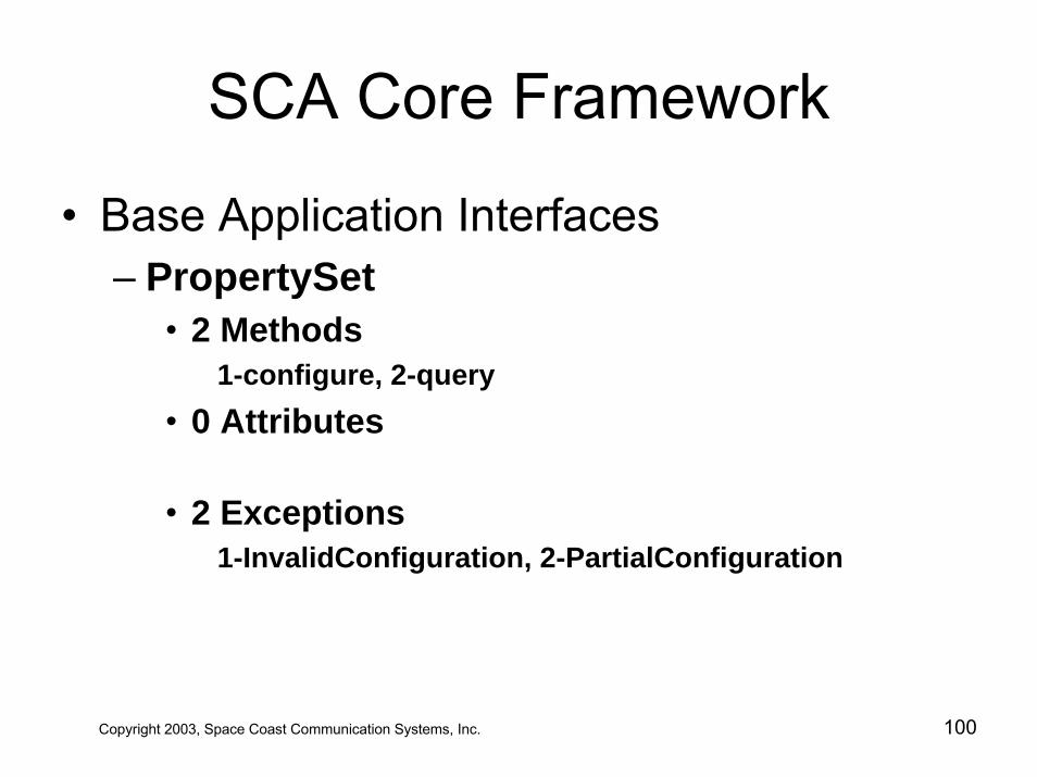
• Base Application Interfaces – PropertySet
• 2 Methods1-configure, 2-query
• 0 Attributes
• 2 Exceptions1-InvalidConfiguration, 2-PartialConfiguration
Copyright 2003, Space Coast Communication Systems, Inc. 100
SCA Core Framework
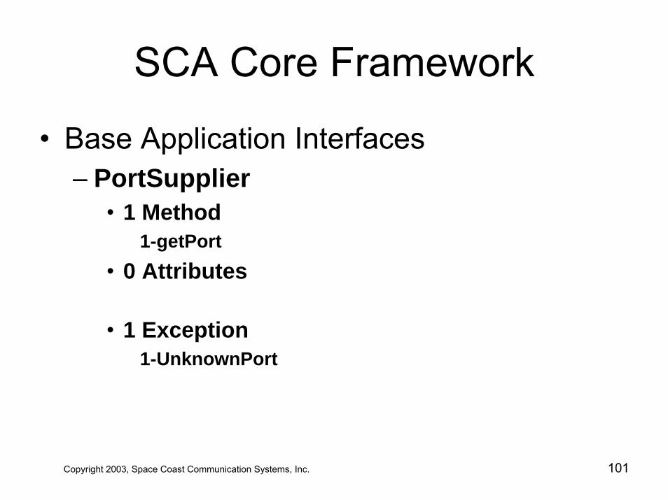
• Base Application Interfaces – PortSupplier
• 1 Method1-getPort
• 0 Attributes
• 1 Exception1-UnknownPort
Copyright 2003, Space Coast Communication Systems, Inc. 101
SCA Core Framework
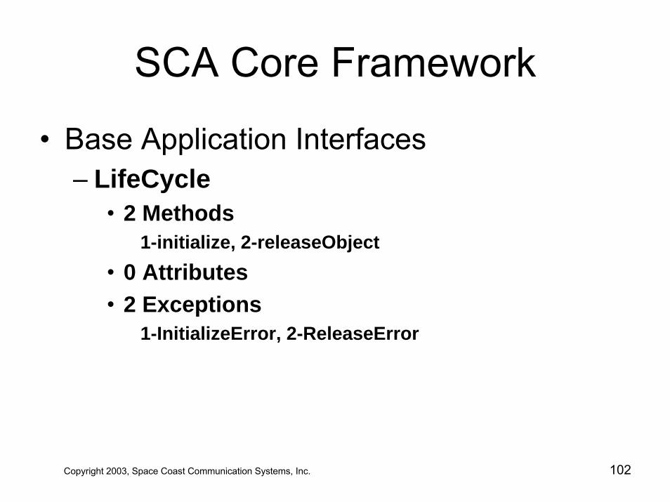
• Base Application Interfaces – LifeCycle
• 2 Methods1-initialize, 2-releaseObject
• 0 Attributes• 2 Exceptions
1-InitializeError, 2-ReleaseError
Copyright 2003, Space Coast Communication Systems, Inc. 102
SCA Core Framework
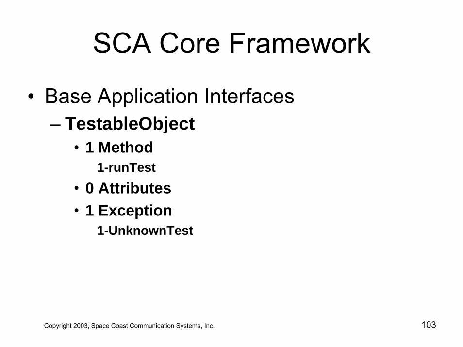
• Base Application Interfaces – TestableObject
• 1 Method1-runTest
• 0 Attributes• 1 Exception
1-UnknownTest
Copyright 2003, Space Coast Communication Systems, Inc. 103
SCA Core Framework
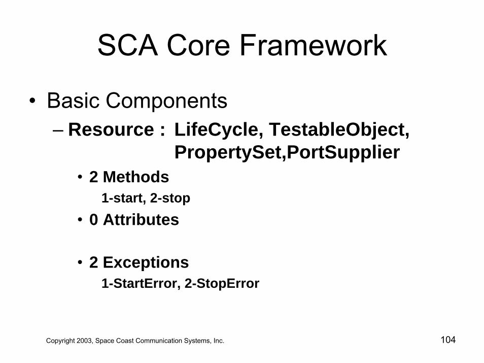
• Basic Components – Resource : LifeCycle, TestableObject,
PropertySet,PortSupplier• 2 Methods
1-start, 2-stop• 0 Attributes
• 2 Exceptions1-StartError, 2-StopError
Copyright 2003, Space Coast Communication Systems, Inc. 104
SCA Core Framework
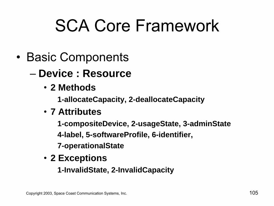
• Basic Components – Device : Resource
• 2 Methods1-allocateCapacity, 2-deallocateCapacity
• 7 Attributes1-compositeDevice, 2-usageState, 3-adminState4-label, 5-softwareProfile, 6-identifier,7-operationalState
• 2 Exceptions1-InvalidState, 2-InvalidCapacity
Copyright 2003, Space Coast Communication Systems, Inc. 105
SCA Core Framework
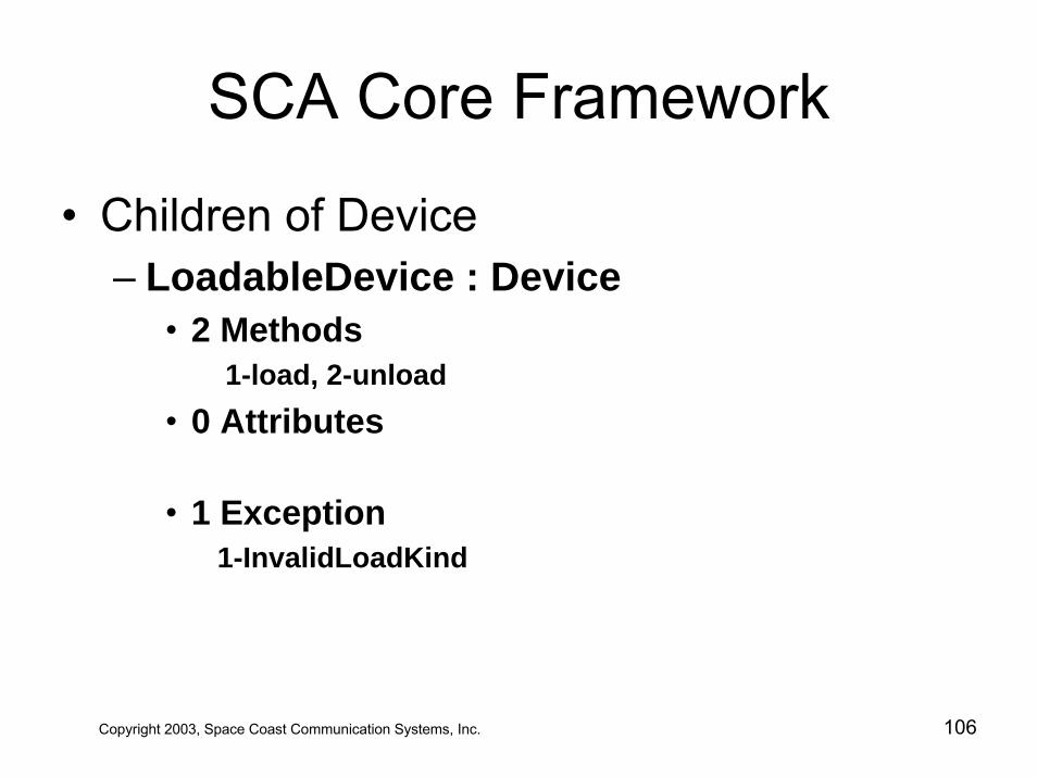
• Children of Device – LoadableDevice : Device
• 2 Methods1-load, 2-unload
• 0 Attributes
• 1 Exception1-InvalidLoadKind
Copyright 2003, Space Coast Communication Systems, Inc. 106
SCA Core Framework
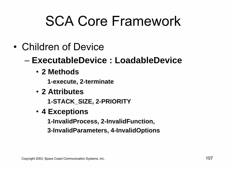
• Children of Device – ExecutableDevice : LoadableDevice
• 2 Methods1-execute, 2-terminate
• 2 Attributes1-STACK_SIZE, 2-PRIORITY
• 4 Exceptions1-InvalidProcess, 2-InvalidFunction, 3-InvalidParameters, 4-InvalidOptions
Copyright 2003, Space Coast Communication Systems, Inc. 107
SCA Core Framework
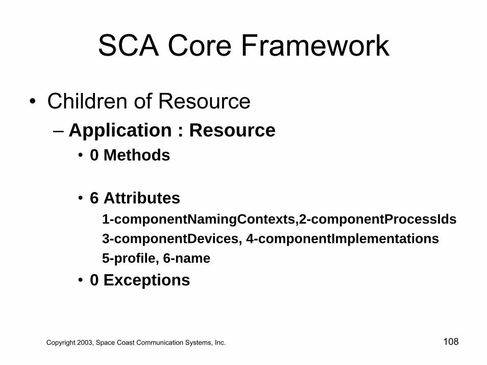
• Children of Resource– Application : Resource
• 0 Methods
• 6 Attributes1-componentNamingContexts,2-componentProcessIds3-componentDevices, 4-componentImplementations5-profile, 6-name
• 0 Exceptions
Copyright 2003, Space Coast Communication Systems, Inc. 108
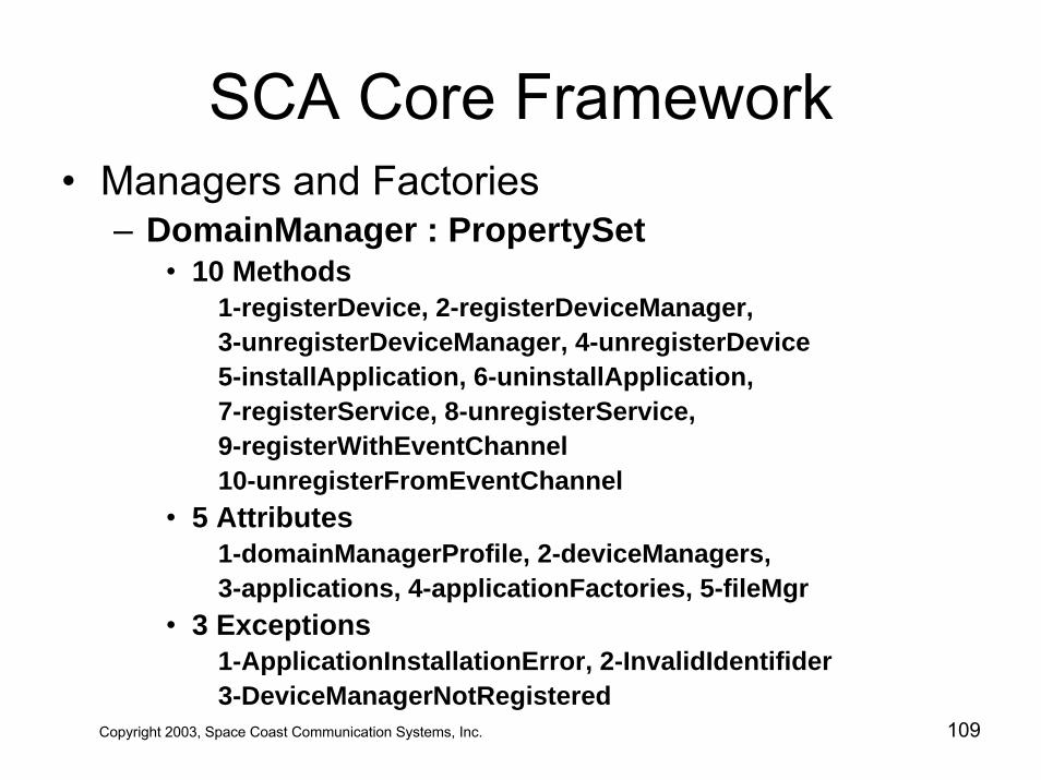
SCA Core Framework• Managers and Factories
– DomainManager : PropertySet• 10 Methods
1-registerDevice, 2-registerDeviceManager, 3-unregisterDeviceManager, 4-unregisterDevice5-installApplication, 6-uninstallApplication,7-registerService, 8-unregisterService,9-registerWithEventChannel10-unregisterFromEventChannel
• 5 Attributes1-domainManagerProfile, 2-deviceManagers,3-applications, 4-applicationFactories, 5-fileMgr
• 3 Exceptions1-ApplicationInstallationError, 2-InvalidIdentifider3-DeviceManagerNotRegistered
Copyright 2003, Space Coast Communication Systems, Inc. 109
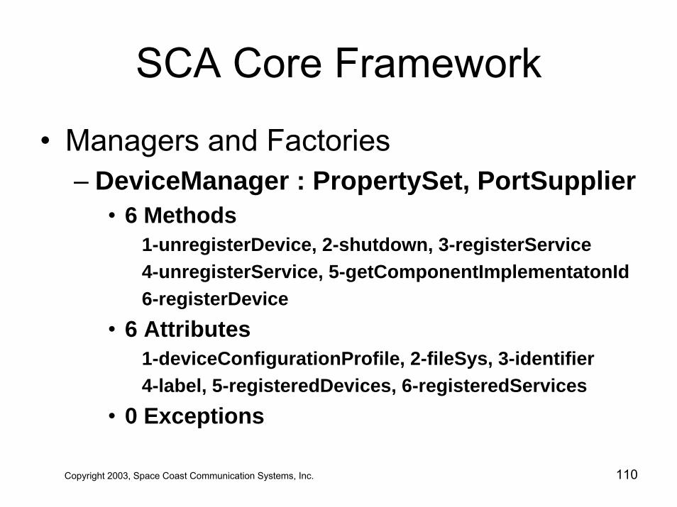
SCA Core Framework
• Managers and Factories – DeviceManager : PropertySet, PortSupplier
• 6 Methods1-unregisterDevice, 2-shutdown, 3-registerService4-unregisterService, 5-getComponentImplementatonId6-registerDevice
• 6 Attributes1-deviceConfigurationProfile, 2-fileSys, 3-identifier4-label, 5-registeredDevices, 6-registeredServices
• 0 Exceptions
Copyright 2003, Space Coast Communication Systems, Inc. 110
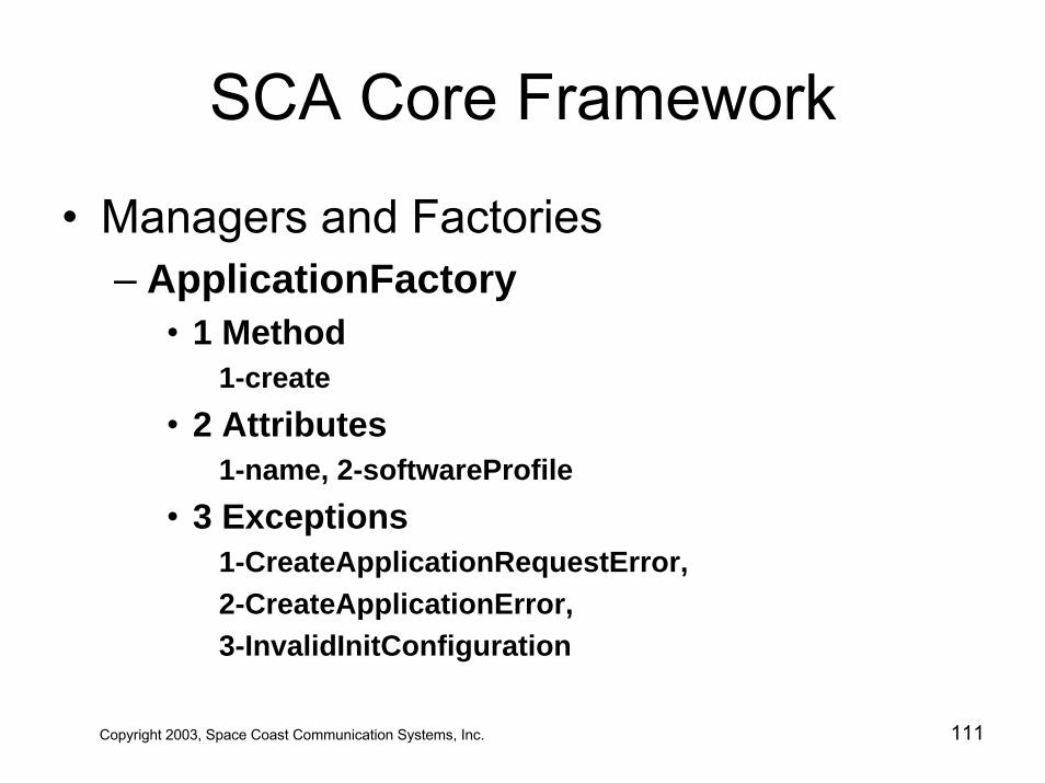
SCA Core Framework
• Managers and Factories – ApplicationFactory
• 1 Method1-create
• 2 Attributes1-name, 2-softwareProfile
• 3 Exceptions1-CreateApplicationRequestError, 2-CreateApplicationError,3-InvalidInitConfiguration
Copyright 2003, Space Coast Communication Systems, Inc. 111
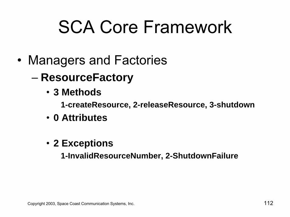
SCA Core Framework
• Managers and Factories – ResourceFactory
• 3 Methods1-createResource, 2-releaseResource, 3-shutdown
• 0 Attributes
• 2 Exceptions 1-InvalidResourceNumber, 2-ShutdownFailure
Copyright 2003, Space Coast Communication Systems, Inc. 112
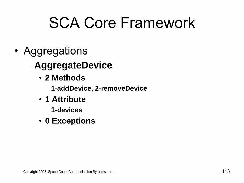
SCA Core Framework
• Aggregations – AggregateDevice
• 2 Methods1-addDevice, 2-removeDevice
• 1 Attribute1-devices
• 0 Exceptions
Copyright 2003, Space Coast Communication Systems, Inc. 113
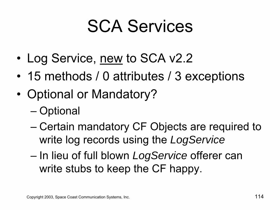
SCA Services
• Log Service, new to SCA v2.2• 15 methods / 0 attributes / 3 exceptions• Optional or Mandatory?
– Optional– Certain mandatory CF Objects are required to
write log records using the LogService– In lieu of full blown LogService offerer can
write stubs to keep the CF happy.
Copyright 2003, Space Coast Communication Systems, Inc. 114
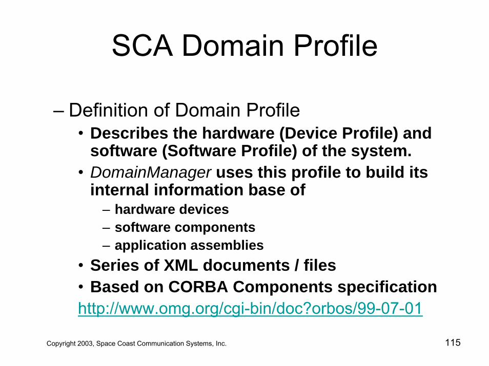
SCA Domain Profile
– Definition of Domain Profile • Describes the hardware (Device Profile) and
software (Software Profile) of the system. • DomainManager uses this profile to build its
internal information base of– hardware devices– software components– application assemblies
• Series of XML documents / files• Based on CORBA Components specificationhttp://www.omg.org/cgi-bin/doc?orbos/99-07-01
Copyright 2003, Space Coast Communication Systems, Inc. 115
SCA Domain ProfileeXtensibleMarkupLanguage
– Developed by World-Wide Web consortiumhttp://www.w3.org/TR/REC-xml
– “XML documents are containers for information”1
– 1 XML Elements of Style, Simon St. Laurent, McGraw-Hill, 2000
Copyright 2003, Space Coast Communication Systems, Inc. 116
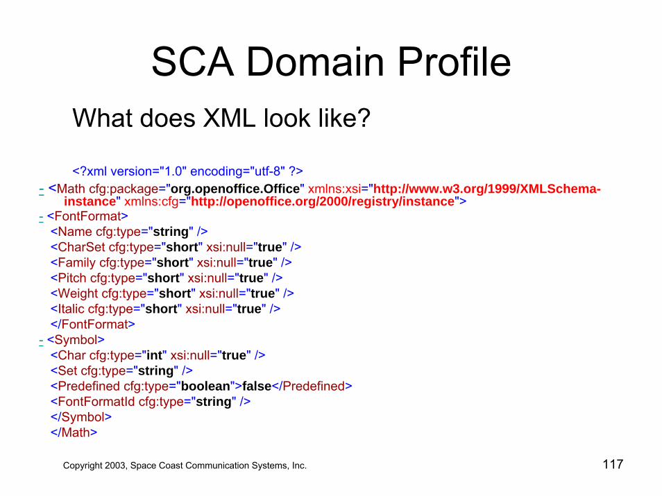
SCA Domain ProfileWhat does XML look like?
<?xml version="1.0" encoding="utf-8" ?>- <Math cfg:package="org.openoffice.Office" xmlns:xsi="http://www.w3.org/1999/XMLSchema-
instance" xmlns:cfg="http://openoffice.org/2000/registry/instance">- <FontFormat>
<Name cfg:type="string" /><CharSet cfg:type="short" xsi:null="true" /><Family cfg:type="short" xsi:null="true" /><Pitch cfg:type="short" xsi:null="true" /><Weight cfg:type="short" xsi:null="true" /><Italic cfg:type="short" xsi:null="true" /></FontFormat>
- <Symbol><Char cfg:type="int" xsi:null="true" /><Set cfg:type="string" /><Predefined cfg:type="boolean">false</Predefined><FontFormatId cfg:type="string" /></Symbol></Math>
Copyright 2003, Space Coast Communication Systems, Inc. 117
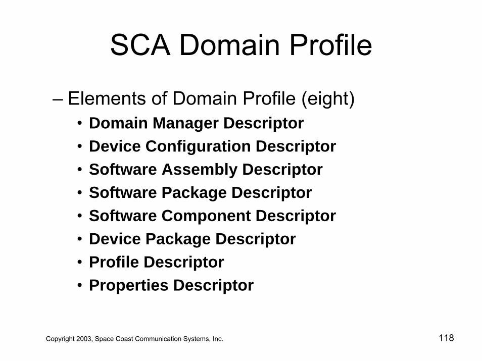
SCA Domain Profile
– Elements of Domain Profile (eight)• Domain Manager Descriptor• Device Configuration Descriptor • Software Assembly Descriptor• Software Package Descriptor• Software Component Descriptor• Device Package Descriptor• Profile Descriptor• Properties Descriptor
Copyright 2003, Space Coast Communication Systems, Inc. 118
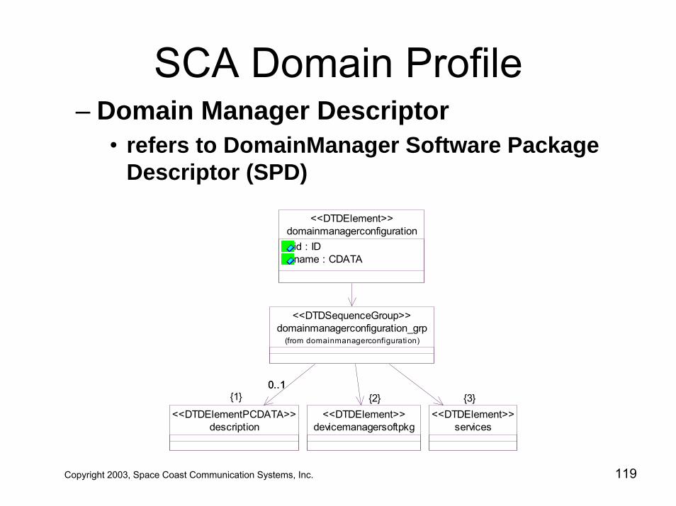
SCA Domain Profile– Domain Manager Descriptor
• refers to DomainManager Software Package Descriptor (SPD)
domainmanagerconfigurationid : IDname : CDATA
<<DTDElement>>
services<<DTDElement>>
description<<DTDElementPCDATA>>
devicemanagersoftpkg<<DTDElement>>
domainmanagerconfiguration_grp(from domainmanagerconfiguration)
<<DTDSequenceGroup>>
{3}0..10..1
{1} {2}
Copyright 2003, Space Coast Communication Systems, Inc. 119
Use of UUID’s• UUID == Universal Unique Identifier• Uniquely identifies objects
– 128-bit numbers guaranteed to be unique– 2^128 ≅ 3.4 x 1038
– The mass of a 180 Jupiter's in micro-grams!– Guaranteed unique through combination of:
• hardware addresses – MAC address, uniquely assigned by IEEE
• time stamps• random seeds
• All SPD’s must have a UUID
Copyright 2003, Space Coast Communication Systems, Inc. 120
SCA Domain Profile
– Software Package Descriptor (SPD)• identifies a software component
implementations• softpkg• name, author, property file• pointer to Software Component Descriptor
Copyright 2003, Space Coast Communication Systems, Inc. 121
SCA Domain Profile
– Software Component Descriptor (SCD)• Documents the component’s interface(s)• Component Description
– resource, device, etc.– inherited interfaces
• Message Ports– provides port– uses port– port “type”: data, control, status, responses, etc.
• IDL interfaces, repository ID
Copyright 2003, Space Coast Communication Systems, Inc. 122
SCA Domain Profile– Properties Descriptor
• Component and Device Attribute Settings• Series of
(id, type, value, units, range)• Supports structured collections of attributes• Select attributes can later be
– query() a.k.a. get– configure() a.k.a set
• Controls which attributes are– visible– settable a.k.a. read-only
Copyright 2003, Space Coast Communication Systems, Inc. 123
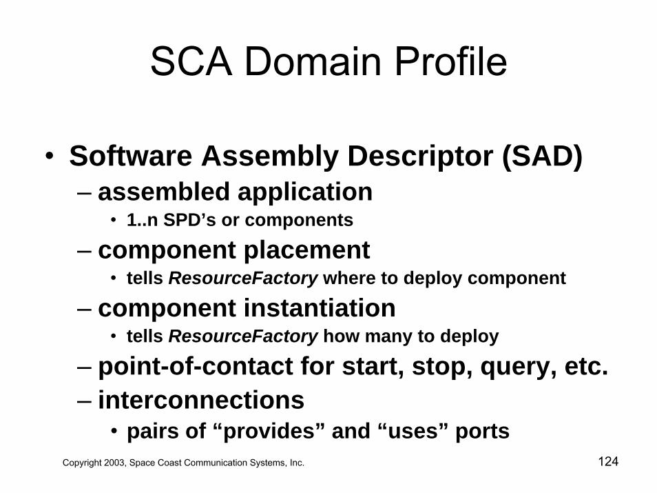
SCA Domain Profile
• Software Assembly Descriptor (SAD)– assembled application
• 1..n SPD’s or components
– component placement• tells ResourceFactory where to deploy component
– component instantiation• tells ResourceFactory how many to deploy
– point-of-contact for start, stop, query, etc. – interconnections
• pairs of “provides” and “uses” portsCopyright 2003, Space Coast Communication Systems, Inc. 124
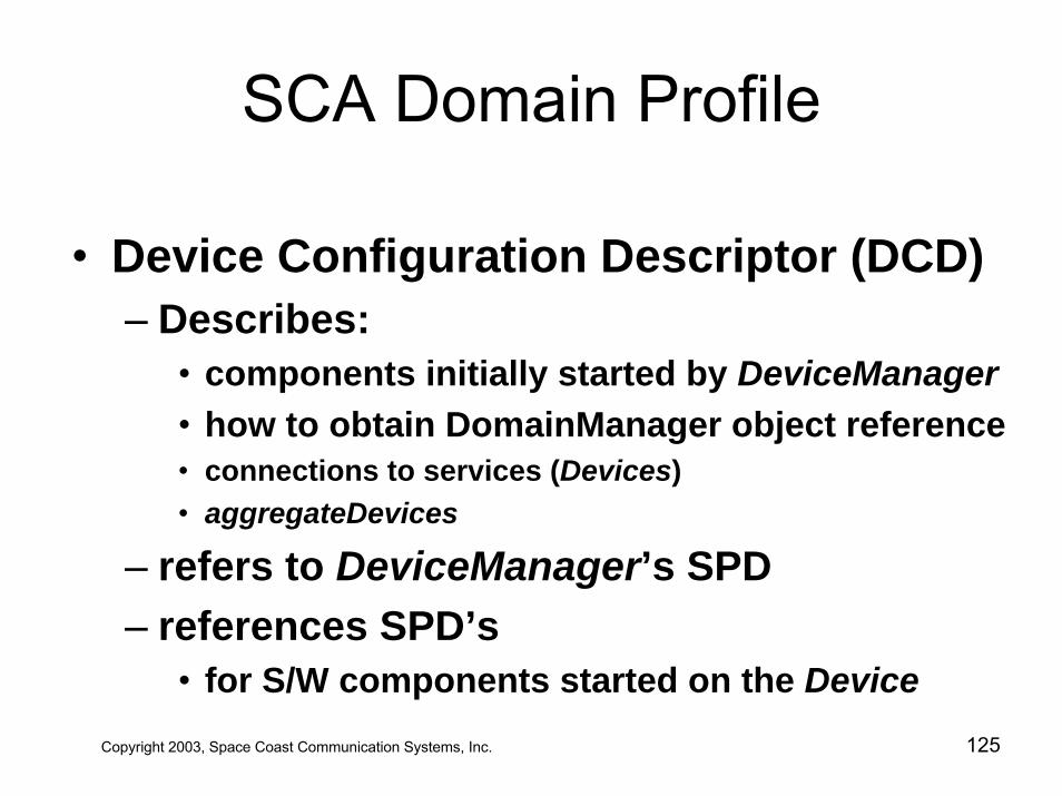
SCA Domain Profile
• Device Configuration Descriptor (DCD)– Describes:
• components initially started by DeviceManager• how to obtain DomainManager object reference• connections to services (Devices)• aggregateDevices
– refers to DeviceManager’s SPD – references SPD’s
• for S/W components started on the DeviceCopyright 2003, Space Coast Communication Systems, Inc. 125
SCA Domain Profile
Copyright 2003, Space Coast Communication Systems, Inc. 126
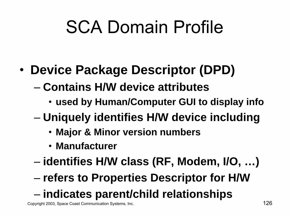
• Device Package Descriptor (DPD)– Contains H/W device attributes
• used by Human/Computer GUI to display info– Uniquely identifies H/W device including
• Major & Minor version numbers• Manufacturer
– identifies H/W class (RF, Modem, I/O, …)– refers to Properties Descriptor for H/W– indicates parent/child relationships
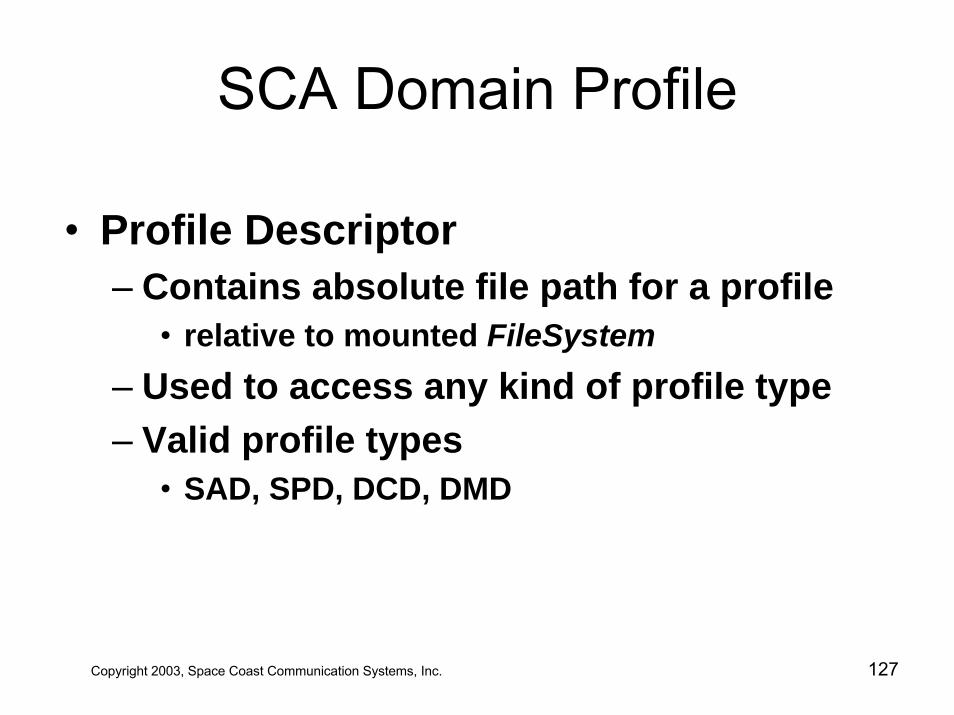
SCA Domain Profile
• Profile Descriptor– Contains absolute file path for a profile
• relative to mounted FileSystem– Used to access any kind of profile type– Valid profile types
• SAD, SPD, DCD, DMD
Copyright 2003, Space Coast Communication Systems, Inc. 127

SCA Domain Profile– Relationship between profile elements
Device Package Descriptor<<DTDElement>>
Profile Descriptor<<DTDElement>>
Properties Descriptor<<DTDElement>>0..n0..n Software Component Descriptor
<<DTDElement>>
0..n0..n
Software Assembly Descriptor<<DTDElement>>
11
Domain Profile
0..n0..n
Software Package Descriptor<<DTDElement>>
11
0..n0..n
0..10..1
1..n1..n
Device Configuration Descriptor<<DTDElement>>
0..n0..n
0..n0..n
1..n1..n
DomainManager Configuration Descriptor
11
11Profile Descriptor<<DTDElement>>
1111
Copyright 2003, Space Coast Communication Systems, Inc. 128
SCA from the Waveform DeveloperStandpoint
• Radio System comes with Operating Environment (OE)– Operating System– Middleware– Core Framework
– Devices & DeviceManager– Application & Application Factory
– Domain Profile
Copyright 2003, Space Coast Communication Systems, Inc. 129
SCA per Waveform Developer
• Developer S/W inherits from CF Objects– Automatically acquire significant functionality
• read/write files• get, connect & disconnect Ports• create & release Resources• load and unload Devices• allocate & deallocate Device capacity
– Software Assembly Descriptor describes how to “wire” Ports together
Copyright 2003, Space Coast Communication Systems, Inc. 130
SCA per Waveform Developer
• Developer Rules of Engagement– OS interface through MANDATORY POSIX API’s
EXCEPT file access– All file access through Core Framework– CORBA interface though minimumCORBA API– Legacy (non-CORBA) interfaces must be wrapped
and appear as Devices• called Adapters
Copyright 2003, Space Coast Communication Systems, Inc. 131
SCA per Waveform Developer• Some simple truths about SCA implementations
– Core Frameworks are not portable– Core Framework source code is not generally
available– Waveform Applications are portable at the source
code level if and only if• Adapters, if used, are available in linkable object code of
the target, i.e. they appear as Devices• All inter-processor and external interfaces are IDL
Copyright 2003, Space Coast Communication Systems, Inc. 132
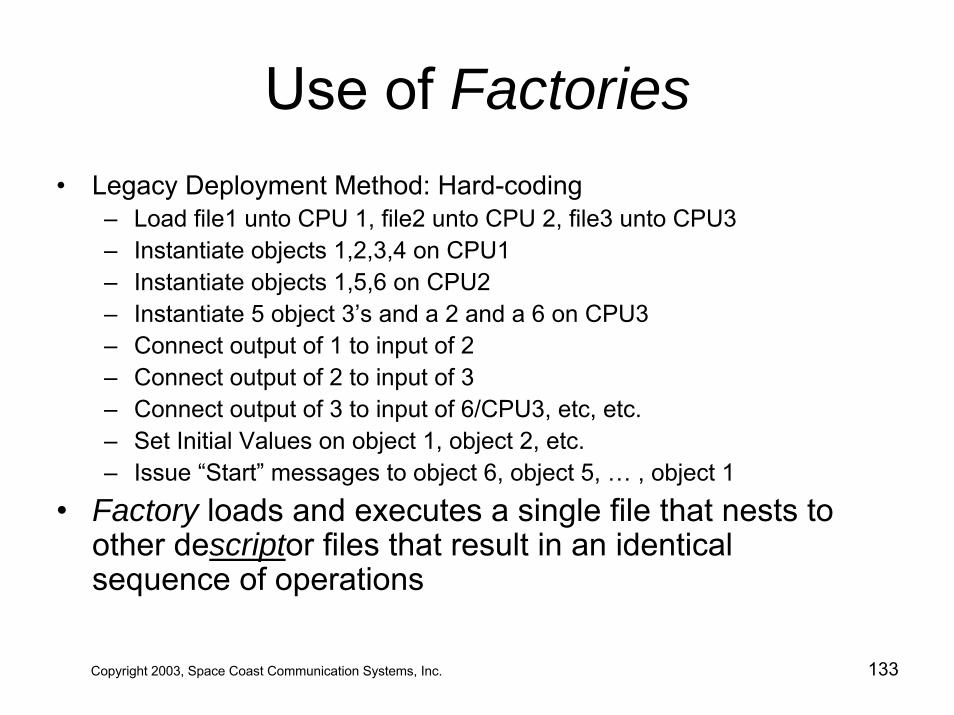
Use of Factories• Legacy Deployment Method: Hard-coding
– Load file1 unto CPU 1, file2 unto CPU 2, file3 unto CPU3– Instantiate objects 1,2,3,4 on CPU1– Instantiate objects 1,5,6 on CPU2– Instantiate 5 object 3’s and a 2 and a 6 on CPU3– Connect output of 1 to input of 2– Connect output of 2 to input of 3– Connect output of 3 to input of 6/CPU3, etc, etc.– Set Initial Values on object 1, object 2, etc.– Issue “Start” messages to object 6, object 5, … , object 1
• Factory loads and executes a single file that nests to other descriptor files that result in an identical sequence of operations
Copyright 2003, Space Coast Communication Systems, Inc. 133
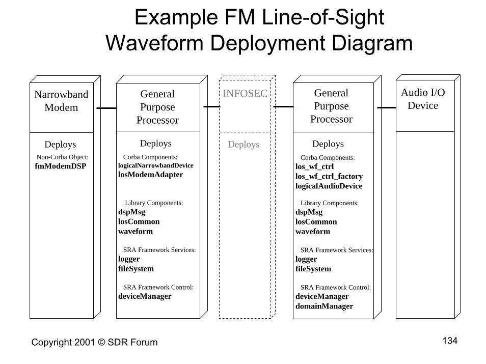
Example FM Line-of-Sight Waveform Deployment Diagram
GeneralPurpose
Processor
DeploysCorba Components:
logicalNarrowbandDevicelosModemAdapter
Library Components:dspMsglosCommonwaveform
SRA Framework Services:loggerfileSystem
SRA Framework Control:deviceManager
NarrowbandModem
DeploysNon-Corba Object:fmModemDSP
INFOSEC
Deploys
GeneralPurpose
Processor
DeploysCorba Components:
los_wf_ctrllos_wf_ctrl_factorylogicalAudioDevice
Library Components:dspMsglosCommonwaveform
SRA Framework Services:loggerfileSystem
SRA Framework Control:deviceManagerdomainManager
Audio I/ODevice
Copyright 2003, Space Coast Communication Systems, Inc. 134Copyright 2001 © SDR Forum
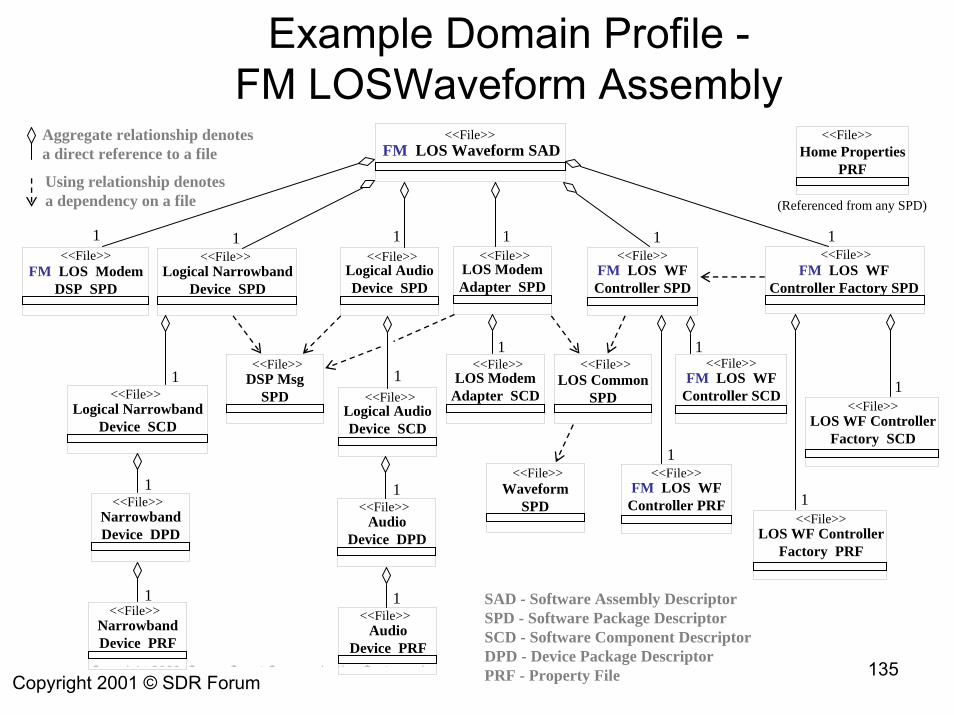
Example Domain Profile -FM LOSWaveform Assembly
Copyright 2003, Space Coast Communication Systems, Inc. 135Copyright 2001 © SDR Forum
1
FM LOS Waveform SAD<<File>>
Logical NarrowbandDevice SPD
<<File>>Logical AudioDevice SPD
<<File>>FM LOS Modem
DSP SPD
<<File>>
Home Properties PRF
<<File>>
LOS WF ControllerFactory SCD
<<File>>
1
1
1
SAD - Software Assembly DescriptorSPD - Software Package DescriptorSCD - Software Component DescriptorDPD - Device Package DescriptorPRF - Property File
(Referenced from any SPD)
Logical NarrowbandDevice SCD
<<File>>Logical AudioDevice SCD
<<File>>DSP Msg
SPD
<<File>>1
NarrowbandDevice DPD
<<File>>1
NarrowbandDevice PRF
<<File>>1
AudioDevice DPD
<<File>>1
AudioDevice PRF
<<File>>1
FM LOS WFController SPD
<<File>> <<File>>FM LOS WF
Controller Factory SPDLOS ModemAdapter SPD
<<File>>
LOS Common SPD
<<File>>
LOS WF ControllerFactory PRF
<<File>>
LOS ModemAdapter SCD
<<File>>FM LOS WF
Controller SCD
<<File>>1
WaveformSPD
<<File>>FM LOS WF
Controller PRF
<<File>>1
Aggregate relationship denotesa direct reference to a file
Using relationship denotesa dependency on a file
1 1 1 1 1 1
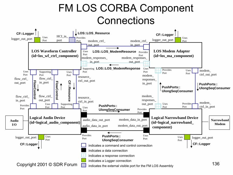
FM LOS CORBA Component Connections
LOS Waveform Controller(id=los_wf_ctrl_component)
LOS Modem Adapter(id=los_ma_component)
Logical Audio Device(id=logical_audio_component)
Logical Narrowband Device(id=logical_narrowband_component)
logger_out_port UsesPort
ProvidesPort
UsesPort
UsesPortUses
PortSupportingPort
CF::Logger LOS::LOS_Resource
UsesPort
SupportingPort
UsesPort
flow_ctrl_out_port
flow_ctrl_in_port
FlowC
ontrolflow_ctrl_out_port
ProvidesPort
SupportingPort
UsesPort
resource_ctrl_in_port
resource_ctrl_out_port
flow_ctrl_in_port
CF::R
esource
ProvidesPort
modem_responses_in_port
UsesPort
ProvidesPort
modem_responses_out_port
Copyright 2003, Space Coast Communication Systems, Inc. 136Copyright 2001 © SDR Forum
PushPorts::UlongSeqConsumer
UsesPort
ProvidesPort
modem_ctrl_in_port
PushPorts::UlongSeqConsumer
modem_ctrl_out_port
FlowC
ontrol
modem_responses_in_port
modem_responses_out_port
LOS::LOS_ModemResponse
HCI_in_port
LOS::LOS_ModemResource
modem_ctrl_in_port
modem_ctrl_out_port
logger_out_portCF::Logger
ProvidesPort
UsesPort
UsesPort
ProvidesPort
audio_data_in_port modem_data_out_port
PushPorts::UlongSeqConsumer
audio_data_out_port modem_data_in_port
PushPorts::UlongSeqConsumer
UsesPort
UsesPort
logger_out_port logger_out_port
CF::LoggerCF::Logger indicates a command and control connectionindicates a data connectionindicates a response connectionindicates a Logger connectionindicates the external visible port for the FM LOS Assembly
NarrowbandModem
AudioI/O
Table of Contents
• JTRS –Today and Tomorrow• JTRS Technology Challenges• JTRS 101 - Understanding SDR • JTRS Clusters• The Software Communications Architecture• JTRS Compliance• JTRS Waveform Applications • JTRS Lessons Learned
Copyright 2003, Space Coast Communication Systems, Inc. 137
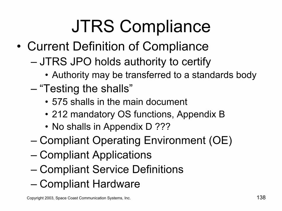
JTRS Compliance• Current Definition of Compliance
– JTRS JPO holds authority to certify• Authority may be transferred to a standards body
– “Testing the shalls”• 575 shalls in the main document• 212 mandatory OS functions, Appendix B• No shalls in Appendix D ???
– Compliant Operating Environment (OE)– Compliant Applications– Compliant Service Definitions– Compliant Hardware
Copyright 2003, Space Coast Communication Systems, Inc. 138
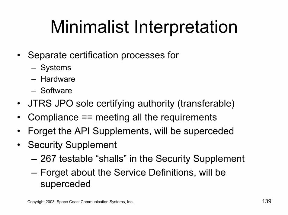
Minimalist Interpretation• Separate certification processes for
– Systems– Hardware– Software
• JTRS JPO sole certifying authority (transferable)• Compliance == meeting all the requirements• Forget the API Supplements, will be superceded• Security Supplement
– 267 testable “shalls” in the Security Supplement– Forget about the Service Definitions, will be
superceded
Copyright 2003, Space Coast Communication Systems, Inc. 139
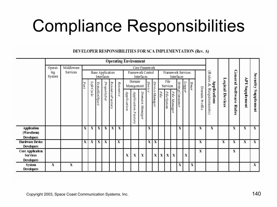
Compliance Responsibilities
Copyright 2003, Space Coast Communication Systems, Inc. 140
Latest SCA Enhancements• Requirements Hiding
– Out of 1099 reqm’ts only 465 are externally visible• Abstraction for Reconfigurable Devices (HAL)• Radio API’s – H/W abstractions• Software Download• Radio Services• Platform Independent Model (PIM)
#1 GoalBackward Compatibility and Portability
Copyright 2003, Space Coast Communication Systems, Inc. 141
Application Program Interface• An API forms an agreement between two components on the
– language and semantics used to communicate– services provided (Service Definitions)– behavior resulting from invocation of operations
• An SCA-compliant API is described using IDL and is formed by inheriting Interfaces derived from previously defined Building Blocks.
• Standardized APIs are essential for portability of applications and interchangeability of devices.
• API’s guarantee Service Provider and User can communicate regardless of OE or programming language.
• Uniquity of API definitions guaranteed via application of UUID
Copyright 2003, Space Coast Communication Systems, Inc. 142
Application Program Interface
I/O
Network
Physical
A
B
WaveformApplication
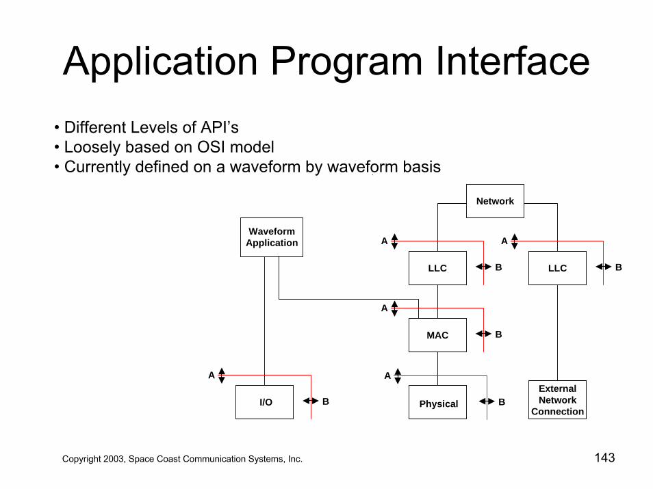
A Data and Real-time Control
B Non-real-time Control, Setup and Initialization,from applications, other levels, user interface
ExternalNetwork
Connection
LLC LLC
MAC
A
B
A
B
A
B
A
B
• Different Levels of API’s• Loosely based on OSI model• Currently defined on a waveform by waveform basis
Copyright 2003, Space Coast Communication Systems, Inc. 143
Application Program Interface• All SCA-compliant APIs shall have their interfaces described in IDL
• Rules of Engagement for API definitions
- Use existing API. - Create a new API via inheritance- Translate an existing non-JTRS API to IDL- Develop a new API based upon one or more Building Blocks.
• Rules of Engagement for API transfer mechanisms
- CORBA- Alternate or non-CORBA transfer mechanism- Documented in IDL, implemented in native language- Commercial or government standard preferred
Copyright 2003, Space Coast Communication Systems, Inc. 144
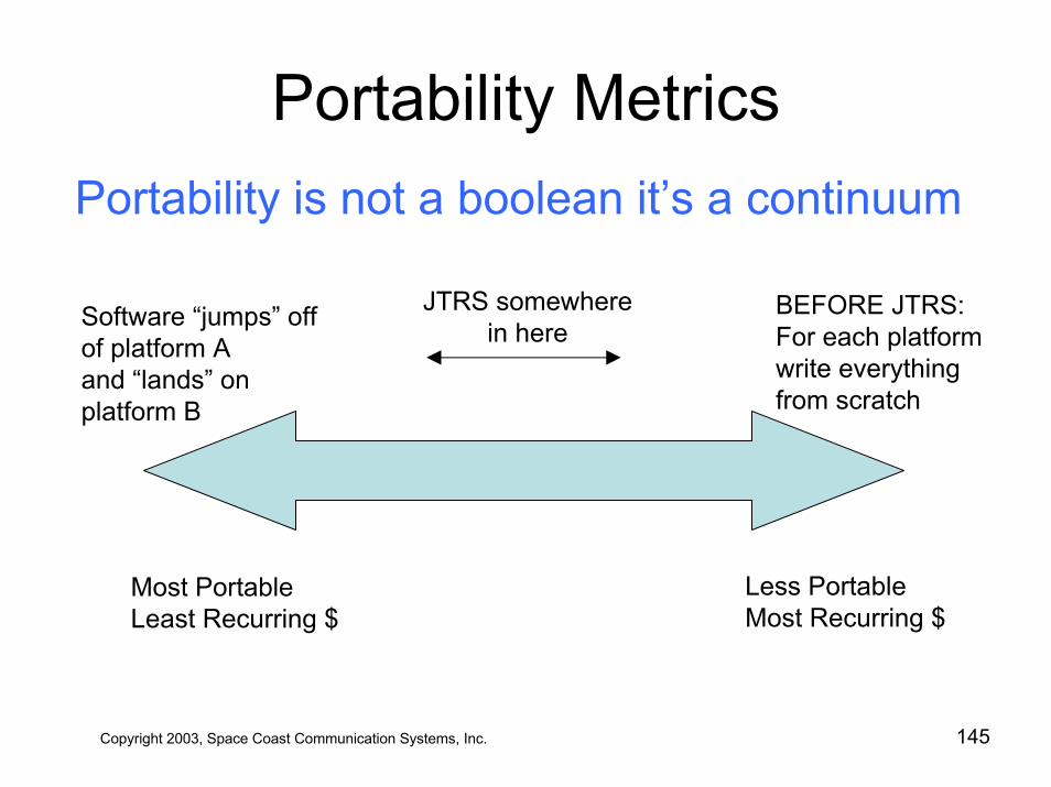
Portability MetricsPortability is not a boolean it’s a continuum
Software “jumps” off of platform Aand “lands” on platform B
BEFORE JTRS:For each platform write everything from scratch
JTRS somewherein here
Less PortableMost Recurring $
Most PortableLeast Recurring $
Copyright 2003, Space Coast Communication Systems, Inc. 145
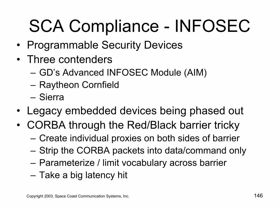
SCA Compliance - INFOSEC• Programmable Security Devices• Three contenders
– GD’s Advanced INFOSEC Module (AIM)– Raytheon Cornfield– Sierra
• Legacy embedded devices being phased out• CORBA through the Red/Black barrier tricky
– Create individual proxies on both sides of barrier– Strip the CORBA packets into data/command only– Parameterize / limit vocabulary across barrier– Take a big latency hit
Copyright 2003, Space Coast Communication Systems, Inc. 146
Table of Contents
• JTRS –Today and Tomorrow• JTRS Technology Challenges• JTRS 101 - Understanding SDR • JTRS Clusters• The Software Communications Architecture• JTRS Compliance• JTRS Waveform Applications • JTRS Lessons Learned
Copyright 2003, Space Coast Communication Systems, Inc. 147
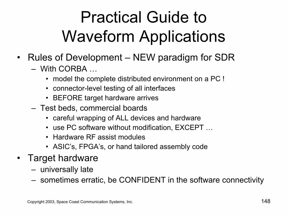
Practical Guide to Waveform Applications
• Rules of Development – NEW paradigm for SDR– With CORBA …
• model the complete distributed environment on a PC !• connector-level testing of all interfaces• BEFORE target hardware arrives
– Test beds, commercial boards• careful wrapping of ALL devices and hardware• use PC software without modification, EXCEPT …• Hardware RF assist modules• ASIC’s, FPGA’s, or hand tailored assembly code
• Target hardware – universally late– sometimes erratic, be CONFIDENT in the software connectivity
Copyright 2003, Space Coast Communication Systems, Inc. 148
Practical Guide to Waveform Applications
• The Holy Grail : Portable Software– avoid anything machine dependent
• in “C”, bit-fields, unions, pragmas, etc.• in Ada, all Appendix M “features” are taboo
avoid automatic conversions• avoid memorizing operator precedence, use parens
– use single source tree for all combinations of • target hardware• operating system
– when absolutely necessary• in “C” use #if (more extensible than #ifdef)
Copyright 2003, Space Coast Communication Systems, Inc. 149
Practical Guide to Waveform Applications
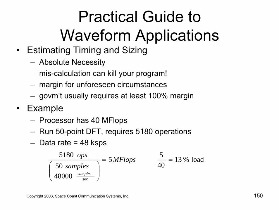
• Estimating Timing and Sizing– Absolute Necessity– mis-calculation can kill your program!– margin for unforeseen circumstances– govm’t usually requires at least 100% margin
• Example– Processor has 40 MFlops– Run 50-point DFT, requires 5180 operations– Data rate = 48 ksps
load%134055
48000505180
sec
==
⎟⎟⎠
⎞⎜⎜⎝
⎛MFlops
samplesops
samples
Copyright 2003, Space Coast Communication Systems, Inc. 150
Practical Guide to Waveform Applications
• Latency and Throughput– packet size vs. latency
• larger packet size, longer latency
– packet size vs. CPU load• larger packet size, lower CPU load
– packet size vs. bus bandwidth• modern buses support bursty communications• bus arbitration• larger packet size fewer arbitrations• slightly longer wait states
– Bus Wait times & Bus bandwidth << OS tick timers
Copyright 2003, Space Coast Communication Systems, Inc. 151
Practical Guide to Waveform Applications
• Latency and Throughput – Operating System– OS runs on tic-timer, < 1 msec. to 0.01 sec. – Principal, 40 S/W engineers running on one RTOS – Common Courtesy, complete your action and …
• yield go to back of the queue• yield go to sleep until awakened by event• lock minimize resource locking• lock never lock a resource and then go to sleep
– Who pre-empted me?– Recommend only 2 priority levels, PRI_HI & PRI_LO– Tasks running at higher priority MUST …
• Be courteous• Carefully contend for a resource locked by a lower task
Copyright 2003, Space Coast Communication Systems, Inc. 152
Practical Guide to Waveform Applications
• Latency and Throughput – Operating System– Always put your server object to sleep for an event– For external events use an interrupt– Interrupt code on target will not be portable– Can abstract interrupt behavior in sim world
• Create an interrupt object– Alternatives
• lowest priority spinning – slightly sluggish, prevents monitor tasks from running
• nanosleeping– more sluggish, smallest quanta of nanosleep == OS tic-
time• both methods dangerously prone to missing an event !
Copyright 2003, Space Coast Communication Systems, Inc. 153
Practical Guide to Waveform Applications
• CORBA Concurrency Models• What’s a concurrency model?• Describes ORB-to-ORB interactions
– Blocking– Reactive– Threaded– Thread-per-Client– Thread-per-Request– Thread Pool
Copyright 2003, Space Coast Communication Systems, Inc. 154
Practical Guide to Waveform Applications
• Blocking Model– Caller blocks until action complete unless oneway– IDL “oneway” says the client expects no reply– Single-threaded version– Server can only accommodate one client at a time– Simple, low overhead– Server is not spinning off new threads every time
there is something to do– Normally too sluggish for most RT applications
Copyright 2003, Space Coast Communication Systems, Inc. 155
Practical Guide to Waveform Applications
• Blocking Model– The oneway myth
• IDL modifier “oneway” tells the ORB to queue the requested action for processing but not to block the caller
• The first call to a method or object suffers a setup time while the ORB is initiating the line of communication with the other ORB(s)
• “Pre-connect” all time critical ORB calls during initialization phase
• Back-to-back calls on a single object or method can block even though they are “oneway” calls
• ORB-to-ORB “book-keeping” is highly implementation dependent
Copyright 2003, Space Coast Communication Systems, Inc. 156
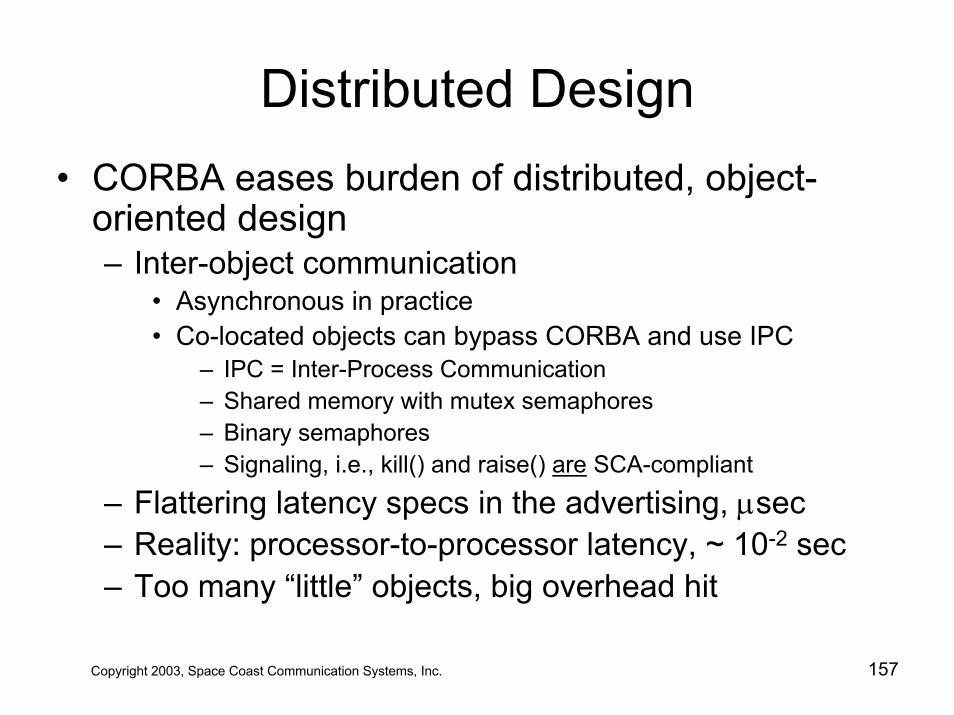
Distributed Design• CORBA eases burden of distributed, object-
oriented design– Inter-object communication
• Asynchronous in practice• Co-located objects can bypass CORBA and use IPC
– IPC = Inter-Process Communication – Shared memory with mutex semaphores– Binary semaphores– Signaling, i.e., kill() and raise() are SCA-compliant
– Flattering latency specs in the advertising, µsec– Reality: processor-to-processor latency, ~ 10-2 sec– Too many “little” objects, big overhead hit
Copyright 2003, Space Coast Communication Systems, Inc. 157
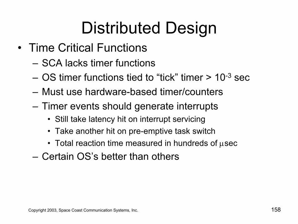
Distributed Design• Time Critical Functions
– SCA lacks timer functions – OS timer functions tied to “tick” timer > 10-3 sec– Must use hardware-based timer/counters – Timer events should generate interrupts
• Still take latency hit on interrupt servicing• Take another hit on pre-emptive task switch• Total reaction time measured in hundreds of µsec
– Certain OS’s better than others
Copyright 2003, Space Coast Communication Systems, Inc. 158
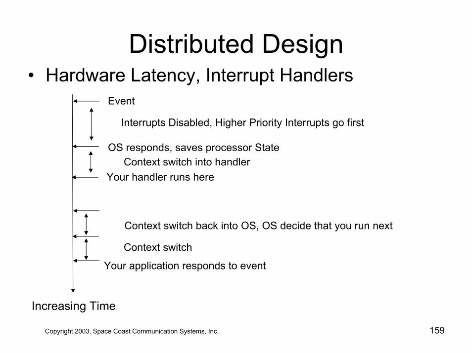
Distributed Design• Hardware Latency, Interrupt Handlers
Event
Interrupts Disabled, Higher Priority Interrupts go first
OS responds, saves processor StateContext switch into handler
Your handler runs here
Context switch back into OS, OS decide that you run next
Context switch
Your application responds to event
Increasing Time
Copyright 2003, Space Coast Communication Systems, Inc. 159
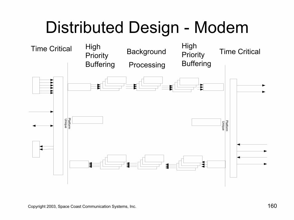
Distributed Design - Modem
Copyright 2003, Space Coast Communication Systems, Inc. 160
PlatformU
nique
PlatformU
nique
Background
Processing
High PriorityBuffering
Time CriticalHigh PriorityBuffering
Time Critical
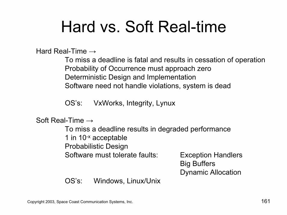
Hard vs. Soft Real-timeHard Real-Time →
To miss a deadline is fatal and results in cessation of operationProbability of Occurrence must approach zeroDeterministic Design and ImplementationSoftware need not handle violations, system is dead
OS’s: VxWorks, Integrity, Lynux
Soft Real-Time →To miss a deadline results in degraded performance1 in 10-x acceptableProbabilistic DesignSoftware must tolerate faults: Exception Handlers
Big BuffersDynamic Allocation
OS’s: Windows, Linux/Unix
Copyright 2003, Space Coast Communication Systems, Inc. 161
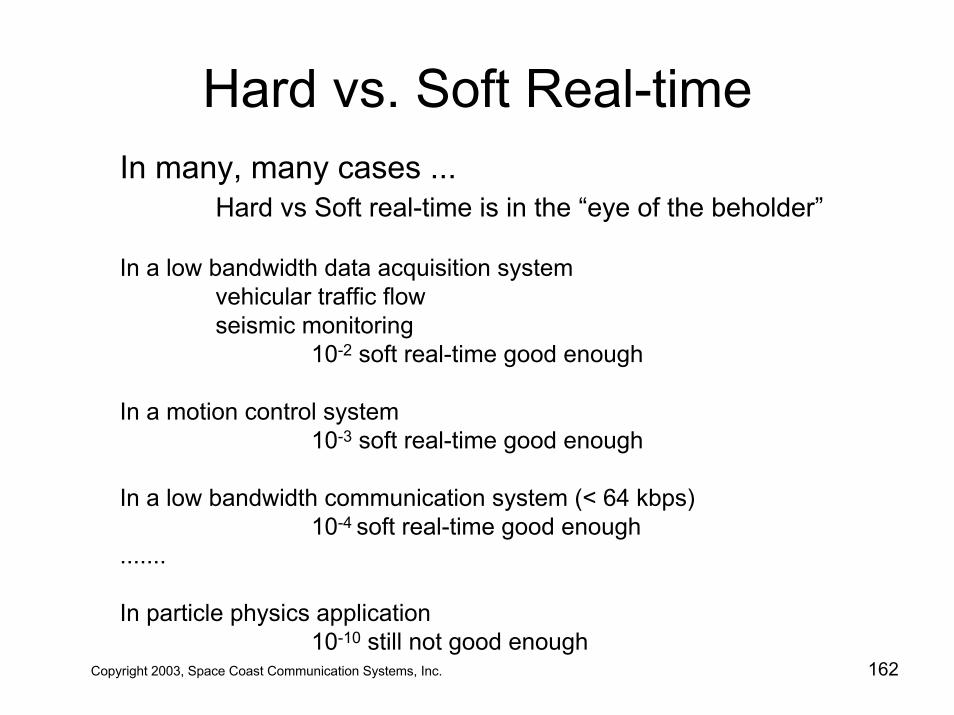
Hard vs. Soft Real-time
Copyright 2003, Space Coast Communication Systems, Inc. 162
In many, many cases ... Hard vs Soft real-time is in the “eye of the beholder”
In a low bandwidth data acquisition systemvehicular traffic flowseismic monitoring
10-2 soft real-time good enough
In a motion control system10-3 soft real-time good enough
In a low bandwidth communication system (< 64 kbps)10-4 soft real-time good enough
.......
In particle physics application10-10 still not good enough
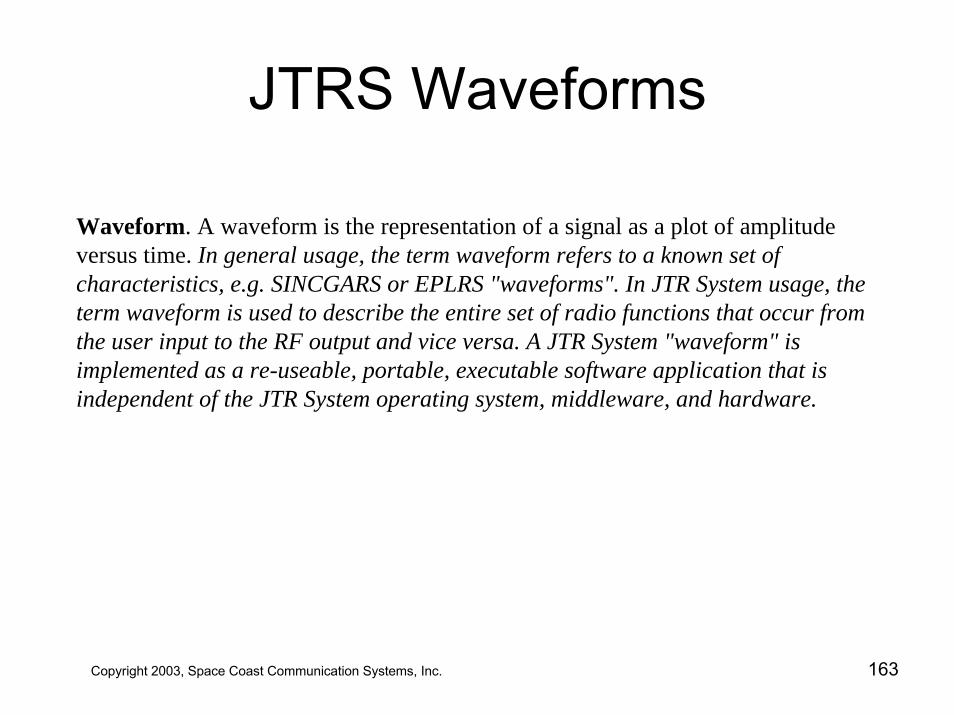
JTRS Waveforms
Waveform. A waveform is the representation of a signal as a plot of amplitude versus time. In general usage, the term waveform refers to a known set of characteristics, e.g. SINCGARS or EPLRS "waveforms". In JTR System usage, the term waveform is used to describe the entire set of radio functions that occur from the user input to the RF output and vice versa. A JTR System "waveform" is implemented as a re-useable, portable, executable software application that is independent of the JTR System operating system, middleware, and hardware.
Copyright 2003, Space Coast Communication Systems, Inc. 163
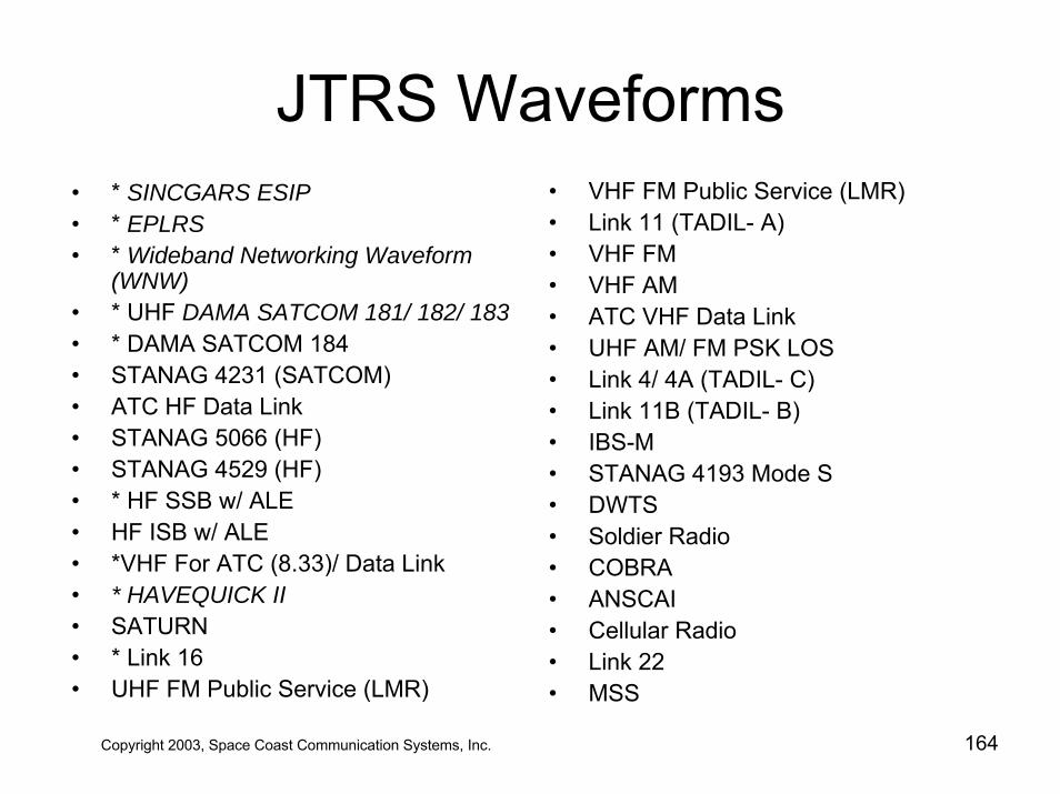
JTRS Waveforms• * SINCGARS ESIP• * EPLRS• * Wideband Networking Waveform
(WNW)• * UHF DAMA SATCOM 181/ 182/ 183• * DAMA SATCOM 184• STANAG 4231 (SATCOM)• ATC HF Data Link• STANAG 5066 (HF)• STANAG 4529 (HF)• * HF SSB w/ ALE• HF ISB w/ ALE• *VHF For ATC (8.33)/ Data Link• * HAVEQUICK II• SATURN• * Link 16• UHF FM Public Service (LMR)
• VHF FM Public Service (LMR)• Link 11 (TADIL- A)• VHF FM• VHF AM• ATC VHF Data Link• UHF AM/ FM PSK LOS• Link 4/ 4A (TADIL- C)• Link 11B (TADIL- B)• IBS-M• STANAG 4193 Mode S• DWTS • Soldier Radio• COBRA• ANSCAI• Cellular Radio• Link 22• MSS
Copyright 2003, Space Coast Communication Systems, Inc. 164
JTRS Waveforms• Capabilities Required. The performance requirements cited
in this section are capabilities for the JTR System or as they apply to each JTR Set configuration. Requirements are denoted as Key Performance Parameters (KPP); Threshold (T) and as Objective (O). These categories are to assist in the evolutionary acquisition process by showing precedence.
Copyright 2003, Space Coast Communication Systems, Inc. 165
JTRS Waveforms• SINCGARS ESIP (Single Channel Ground and Airborne Radio System)
– SINCGARS is a family of VHF-FM combat net radios which provides the primary means of command and control for Infantry, Armor and Artillery Units.
– Bandwidth: 25kHz– Center Frequency Range: 30-88 MHz– Data Rates: 16Kbps– Performance Requirements: K - T– Encryption: KY-57/58, KYV-5– Enhanced SINCGARS Improvement Program (ESIP) - analog and 16 KBPS
digital voce as well as at data rates of 75 BPS and 16 KBPS. SINCGARS will be compliant with MIL-STD-188-220 and 241-1/2.
– Single channel (SC) or frequency hopped (FH) modes– Cipher Text (CT) or Plain Text (PT)– Separate Internet Controller (INC) module performs IP routing on the SINCGARS net – ATC is developing JTRS SINCGARS for use in now and future Clusters
Copyright 2003, Space Coast Communication Systems, Inc. 166
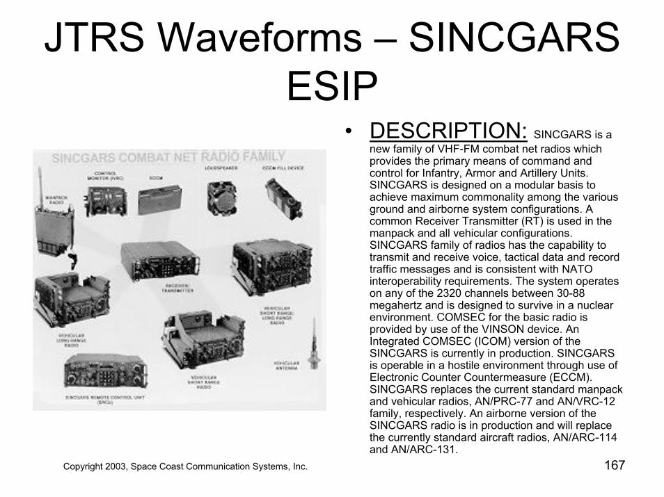
JTRS Waveforms – SINCGARS ESIP
• DESCRIPTION: SINCGARS is a new family of VHF-FM combat net radios which provides the primary means of command and control for Infantry, Armor and Artillery Units. SINCGARS is designed on a modular basis to achieve maximum commonality among the various ground and airborne system configurations. A common Receiver Transmitter (RT) is used in the manpack and all vehicular configurations. SINCGARS family of radios has the capability to transmit and receive voice, tactical data and record traffic messages and is consistent with NATO interoperability requirements. The system operates on any of the 2320 channels between 30-88 megahertz and is designed to survive in a nuclear environment. COMSEC for the basic radio is provided by use of the VINSON device. An Integrated COMSEC (ICOM) version of the SINCGARS is currently in production. SINCGARS is operable in a hostile environment through use of Electronic Counter Countermeasure (ECCM). SINCGARS replaces the current standard manpack and vehicular radios, AN/PRC-77 and AN/VRC-12 family, respectively. An airborne version of the SINCGARS radio is in production and will replace the currently standard aircraft radios, AN/ARC-114 and AN/ARC-131.
Copyright 2003, Space Coast Communication Systems, Inc. 167
JTRS Waveforms• EPLRS
– EPLRS Operates in the 420-450 MHZ frequency range. EPLRS will operate in the data mode at 57 KBPS VHSIC SIP and 228 KBPS VECP. EPLRS will be compliant with CDRL-4002W-001A.
– EPLRS primary purpose is to provide the digital backbone radio frequency communications to support connectivity of the C4I tactical data networks from regimental to company level.
– Bandwidth: 3 MHz– Center Frequency Range: 420-450 MHz– Data Rates: 57 Kbps VHSIC SIP, 114 Kbps VECP– Waveform Type: multiple modes: CSMA, TDMA, CDMA, FDMA– Encryption: KOK-13 (key generator), KGV-13 TRANSEC/COMSEC– The Receiver Transmitter (RT) is a transceiver with an embedded Controlled
Cryptographic Item (CCI) module, the KGV-13. It provides for dual-level secure data communications at either Confidential or Secret level between RTs. The RT can be equipped with two interfaces; Army Data Distribution System Interface (ADDSI), a subset of the X.25 protocol, and the MIL-STD 1553 interface.
– EPLRS Radio Set: AN/PSQ-4 EPLRS Radio
Copyright 2003, Space Coast Communication Systems, Inc. 168
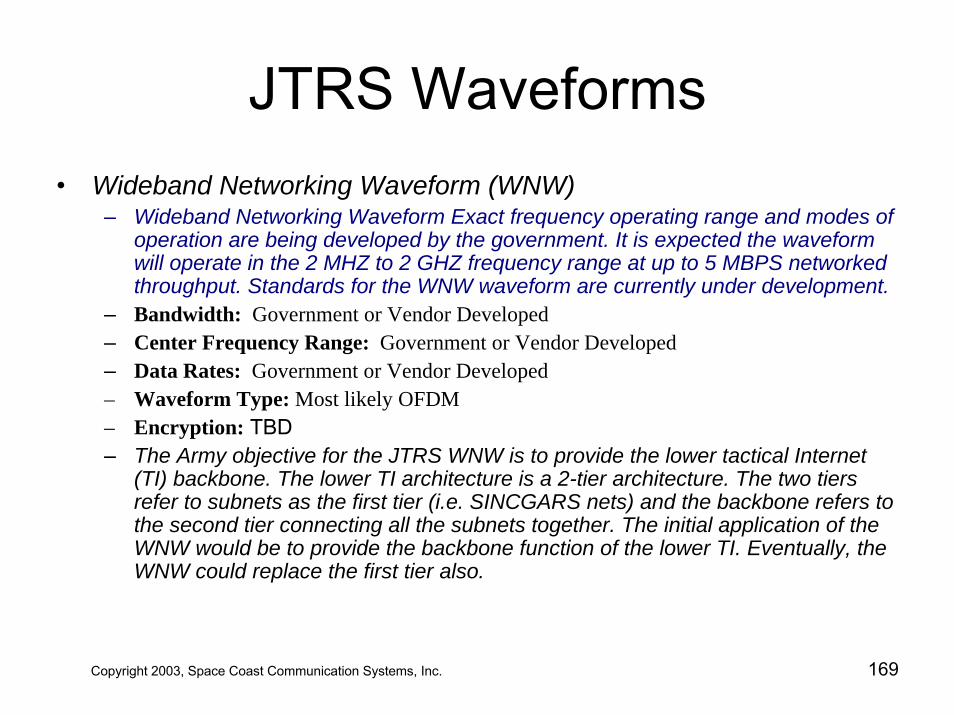
JTRS Waveforms• Wideband Networking Waveform (WNW)
– Wideband Networking Waveform Exact frequency operating range and modes of operation are being developed by the government. It is expected the waveform will operate in the 2 MHZ to 2 GHZ frequency range at up to 5 MBPS networked throughput. Standards for the WNW waveform are currently under development.
– Bandwidth: Government or Vendor Developed– Center Frequency Range: Government or Vendor Developed – Data Rates: Government or Vendor Developed– Waveform Type: Most likely OFDM– Encryption: TBD– The Army objective for the JTRS WNW is to provide the lower tactical Internet
(TI) backbone. The lower TI architecture is a 2-tier architecture. The two tiers refer to subnets as the first tier (i.e. SINCGARS nets) and the backbone refers to the second tier connecting all the subnets together. The initial application of the WNW would be to provide the backbone function of the lower TI. Eventually, the WNW could replace the first tier also.
Copyright 2003, Space Coast Communication Systems, Inc. 169
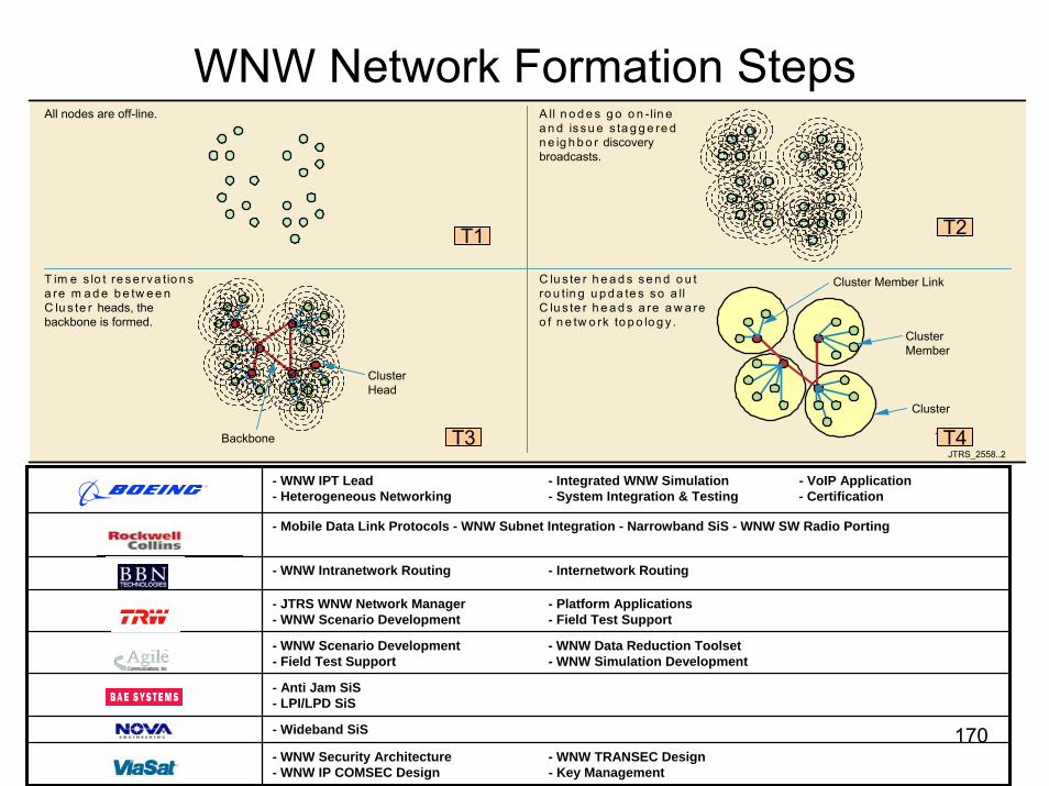
WNW Network Formation Steps
Copyright 2003, Space Coast Communication Systems, Inc. 170
JTRS_2558..2
All nodes are off-line. A ll n o d e s g o o n - lin ea n d issu e s ta g g e re dn e ig h b o r discoverybroadcasts.
T im e s lo t re se rva tio n sa re m a d e b e tw e e nC lu s te r heads, thebackbone is formed.
C lu s te r h e a d s se n d o u tro u tin g u p d a te s so a llC lu s te r h e a d s a re a w a reo f n e tw o rk to p o lo g y .
Cluster
ClusterHead
ClusterMember
Cluster Member Link
Backbone
T=0 T=1
T=10 T=20
- WNW IPT Lead - Integrated WNW Simulation - VoIP Application- Heterogeneous Networking - System Integration & Testing - Certification
- Mobile Data Link Protocols - WNW Subnet Integration - Narrowband SiS - WNW SW Radio Porting
- WNW Intranetwork Routing - Internetwork Routing
- JTRS WNW Network Manager - Platform Applications- WNW Scenario Development - Field Test Support
- WNW Scenario Development - WNW Data Reduction Toolset- Field Test Support - WNW Simulation Development
- Anti Jam SiS- LPI/LPD SiS
- Wideband SiS
- WNW Security Architecture - WNW TRANSEC Design- WNW IP COMSEC Design - Key Management
T1 T2
T3 T4
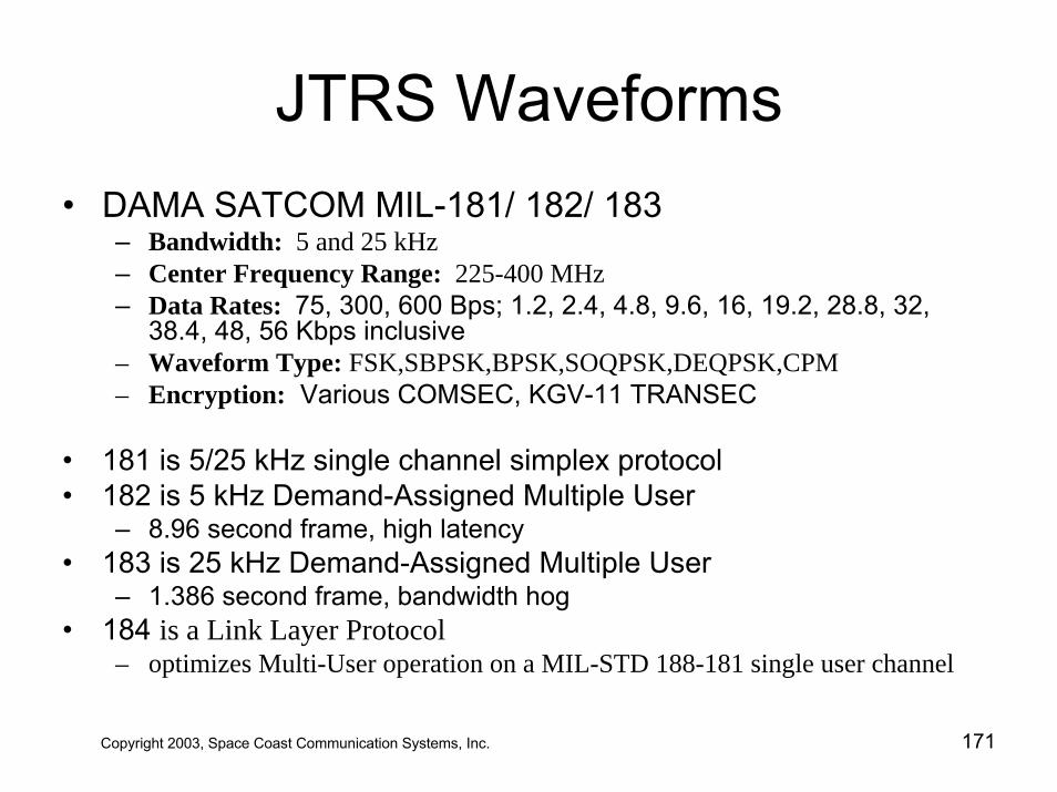
JTRS Waveforms• DAMA SATCOM MIL-181/ 182/ 183
– Bandwidth: 5 and 25 kHz– Center Frequency Range: 225-400 MHz– Data Rates: 75, 300, 600 Bps; 1.2, 2.4, 4.8, 9.6, 16, 19.2, 28.8, 32,
38.4, 48, 56 Kbps inclusive– Waveform Type: FSK,SBPSK,BPSK,SOQPSK,DEQPSK,CPM– Encryption: Various COMSEC, KGV-11 TRANSEC
• 181 is 5/25 kHz single channel simplex protocol• 182 is 5 kHz Demand-Assigned Multiple User
– 8.96 second frame, high latency• 183 is 25 kHz Demand-Assigned Multiple User
– 1.386 second frame, bandwidth hog• 184 is a Link Layer Protocol
– optimizes Multi-User operation on a MIL-STD 188-181 single user channel
Copyright 2003, Space Coast Communication Systems, Inc. 171
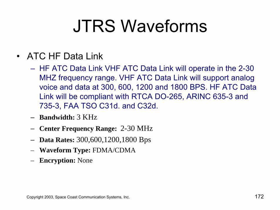
JTRS Waveforms• ATC HF Data Link
– HF ATC Data Link VHF ATC Data Link will operate in the 2-30 MHZ frequency range. VHF ATC Data Link will support analog voice and data at 300, 600, 1200 and 1800 BPS. HF ATC Data Link will be compliant with RTCA DO-265, ARINC 635-3 and 735-3, FAA TSO C31d. and C32d.
– Bandwidth: 3 KHz – Center Frequency Range: 2-30 MHz – Data Rates: 300,600,1200,1800 Bps – Waveform Type: FDMA/CDMA– Encryption: None
Copyright 2003, Space Coast Communication Systems, Inc. 172
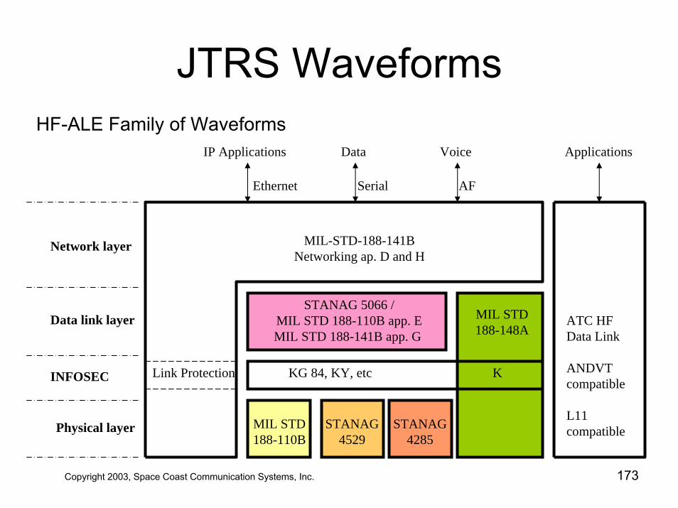
JTRS WaveformsHF-ALE Family of Waveforms
Network layer
Data link layer
INFOSEC
Physical layer
MIL-STD-188-141BNetworking ap. D and H
STANAG 5066 /MIL STD 188-110B app. EMIL STD 188-141B app. G
MIL STD188-148A
KG 84, KY, etc KLink Protection
MIL STD188-110B
STANAG4529
STANAG4285
ATC HFData Link
ANDVT compatible
L11 compatible
ApplicationsIP Applications Data Voice
AFSerialEthernet
Copyright 2003, Space Coast Communication Systems, Inc. 173
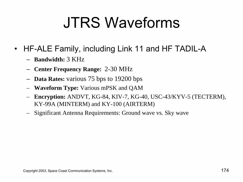
JTRS Waveforms• HF-ALE Family, including Link 11 and HF TADIL-A
– Bandwidth: 3 KHz – Center Frequency Range: 2-30 MHz – Data Rates: various 75 bps to 19200 bps – Waveform Type: Various mPSK and QAM– Encryption: ANDVT, KG-84, KIV-7, KG-40, USC-43/KYV-5 (TECTERM),
KY-99A (MINTERM) and KY-100 (AIRTERM)– Significant Antenna Requirements: Ground wave vs. Sky wave
Copyright 2003, Space Coast Communication Systems, Inc. 174
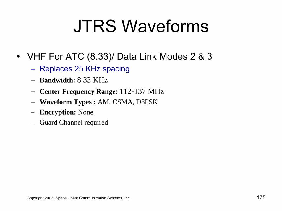
JTRS Waveforms• VHF For ATC (8.33)/ Data Link Modes 2 & 3
– Replaces 25 KHz spacing– Bandwidth: 8.33 KHz – Center Frequency Range: 112-137 MHz – Waveform Types : AM, CSMA, D8PSK – Encryption: None– Guard Channel required
Copyright 2003, Space Coast Communication Systems, Inc. 175
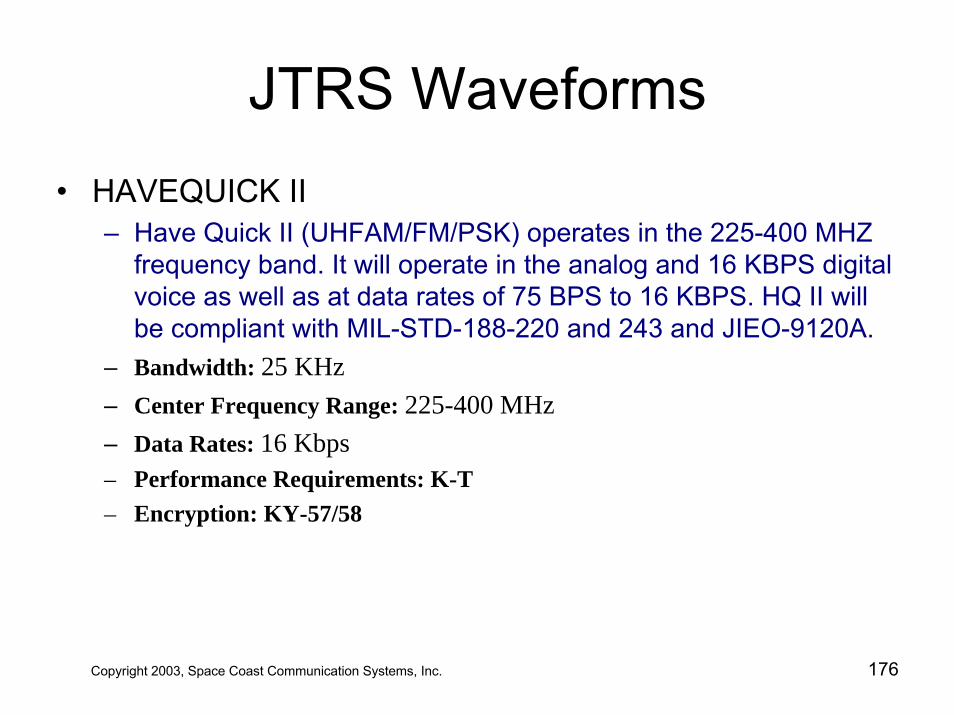
JTRS Waveforms• HAVEQUICK II
– Have Quick II (UHFAM/FM/PSK) operates in the 225-400 MHZ frequency band. It will operate in the analog and 16 KBPS digital voice as well as at data rates of 75 BPS to 16 KBPS. HQ II will be compliant with MIL-STD-188-220 and 243 and JIEO-9120A.
– Bandwidth: 25 KHz – Center Frequency Range: 225-400 MHz – Data Rates: 16 Kbps – Performance Requirements: K-T– Encryption: KY-57/58
Copyright 2003, Space Coast Communication Systems, Inc. 176
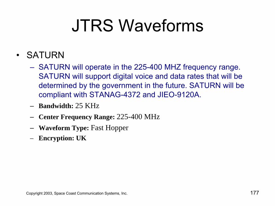
JTRS Waveforms• SATURN
– SATURN will operate in the 225-400 MHZ frequency range. SATURN will support digital voice and data rates that will be determined by the government in the future. SATURN will be compliant with STANAG-4372 and JIEO-9120A.
– Bandwidth: 25 KHz – Center Frequency Range: 225-400 MHz – Waveform Type: Fast Hopper – Encryption: UK
Copyright 2003, Space Coast Communication Systems, Inc. 177
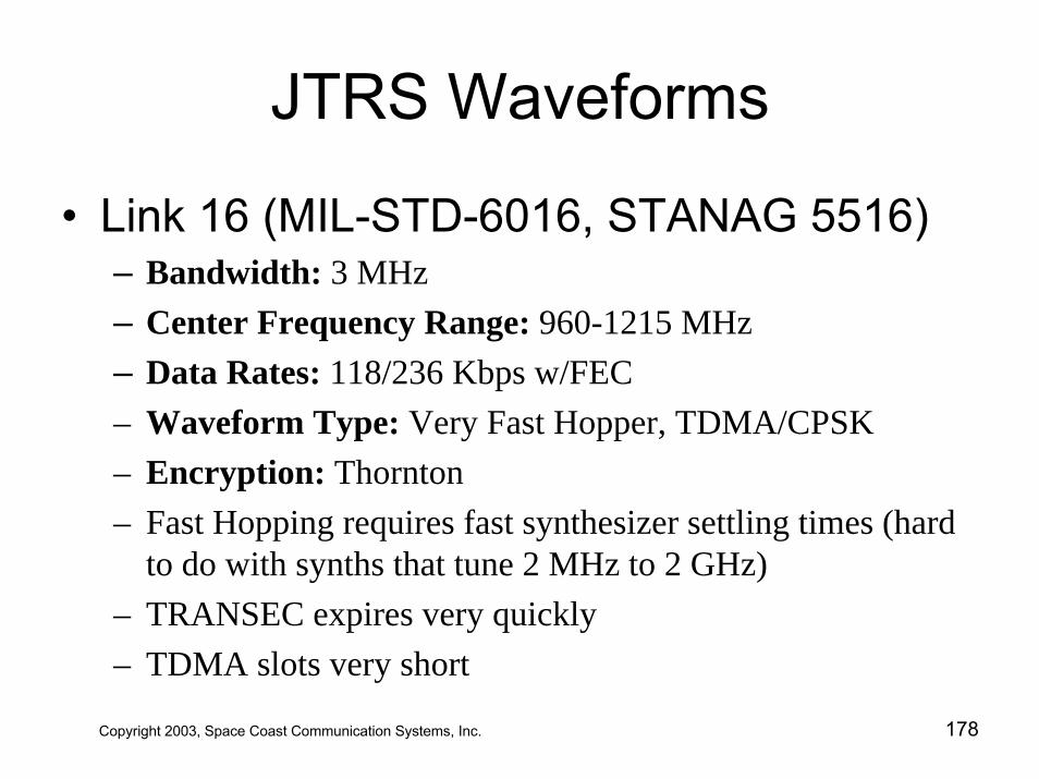
JTRS Waveforms
• Link 16 (MIL-STD-6016, STANAG 5516)– Bandwidth: 3 MHz– Center Frequency Range: 960-1215 MHz– Data Rates: 118/236 Kbps w/FEC– Waveform Type: Very Fast Hopper, TDMA/CPSK– Encryption: Thornton– Fast Hopping requires fast synthesizer settling times (hard
to do with synths that tune 2 MHz to 2 GHz)– TRANSEC expires very quickly– TDMA slots very short
Copyright 2003, Space Coast Communication Systems, Inc. 178
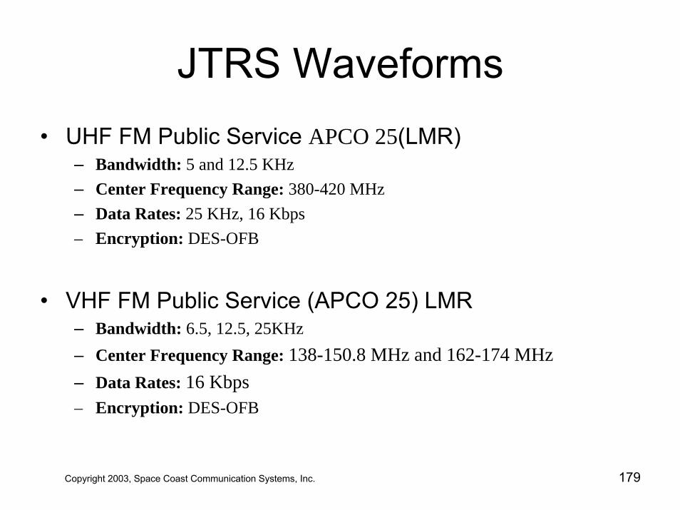
JTRS Waveforms• UHF FM Public Service APCO 25(LMR)
– Bandwidth: 5 and 12.5 KHz– Center Frequency Range: 380-420 MHz– Data Rates: 25 KHz, 16 Kbps – Encryption: DES-OFB
• VHF FM Public Service (APCO 25) LMR– Bandwidth: 6.5, 12.5, 25KHz– Center Frequency Range: 138-150.8 MHz and 162-174 MHz– Data Rates: 16 Kbps – Encryption: DES-OFB
Copyright 2003, Space Coast Communication Systems, Inc. 179
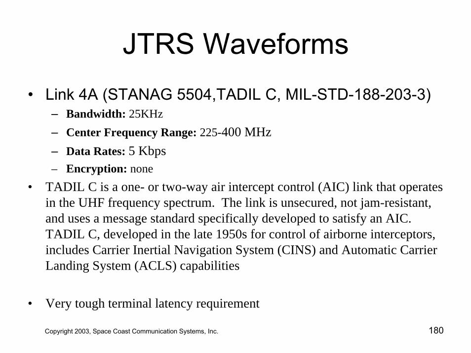
JTRS Waveforms• Link 4A (STANAG 5504,TADIL C, MIL-STD-188-203-3)
– Bandwidth: 25KHz– Center Frequency Range: 225-400 MHz– Data Rates: 5 Kbps – Encryption: none
• TADIL C is a one- or two-way air intercept control (AIC) link that operates in the UHF frequency spectrum. The link is unsecured, not jam-resistant, and uses a message standard specifically developed to satisfy an AIC. TADIL C, developed in the late 1950s for control of airborne interceptors, includes Carrier Inertial Navigation System (CINS) and Automatic Carrier Landing System (ACLS) capabilities
• Very tough terminal latency requirement
Copyright 2003, Space Coast Communication Systems, Inc. 180
JTRS Waveforms• Integrated Broadcast Service Module (IBS-M)
– Bandwidth: 5 and 25KHz– Center Frequency Range: 225-400 MHz– Data Rates: 19.2 Kbps (tunable 2.4, 4.8, 9.6, 19.2)– Waveform Type: BPSK, SOQPSK, LOS or SATCOM TDMA– Encryption: KGV-11
• IBS is the follow on to TRIXS, TRAP/TADIXS/TDDS and TIBS
Copyright 2003, Space Coast Communication Systems, Inc. 181
JTRS Waveforms• STANAG 4193 Mode S Level 4/5
– Bandwidth: 3.5 MHz/3 MHz– Center Frequency Range: 1030-1090 MHz– Data Rates: UK– Performance Requirements: Low Latency– Encryption: UK
• Identification Friend-or-Foe (IFF) Mark XII System and Air Traffic Control Radar Beacon System
Copyright 2003, Space Coast Communication Systems, Inc. 182
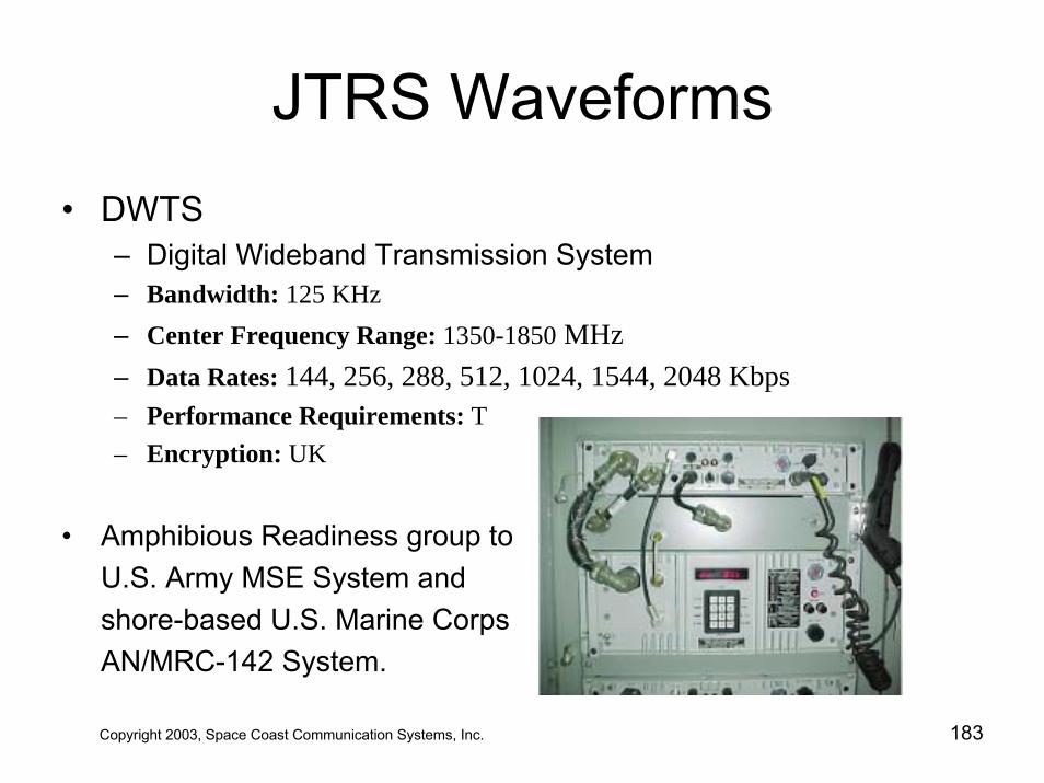
JTRS Waveforms• DWTS
– Digital Wideband Transmission System– Bandwidth: 125 KHz– Center Frequency Range: 1350-1850 MHz– Data Rates: 144, 256, 288, 512, 1024, 1544, 2048 Kbps– Performance Requirements: T– Encryption: UK
• Amphibious Readiness group to U.S. Army MSE System and shore-based U.S. Marine Corps AN/MRC-142 System.
Copyright 2003, Space Coast Communication Systems, Inc. 183
JTRS Waveforms• Soldier Radio / WLAN Soldier Radio
– Bandwidth: 25 KHz – Center Frequency Range: 1.75 –1.85 GHz– Data Rates: 16 Kbps / 1 Mbps– Performance Requirements: T– Encryption: UK
• Supports digital 16 Kbps voice and data at 1 Mbps • WLAN Soldier compliant with IEEE 802.11b, 802.11e and 802.11g.
Copyright 2003, Space Coast Communication Systems, Inc. 184
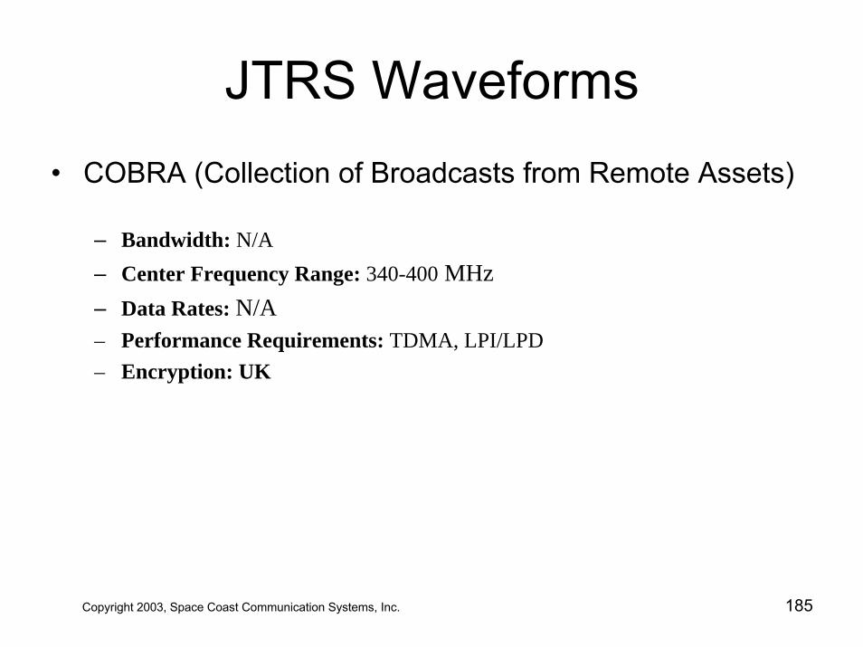
JTRS Waveforms• COBRA (Collection of Broadcasts from Remote Assets)
– Bandwidth: N/A– Center Frequency Range: 340-400 MHz– Data Rates: N/A– Performance Requirements: TDMA, LPI/LPD– Encryption: UK
Copyright 2003, Space Coast Communication Systems, Inc. 185
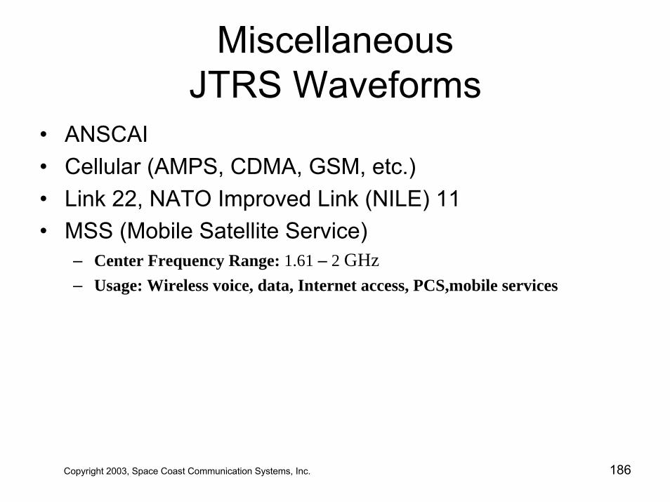
Miscellaneous JTRS Waveforms
• ANSCAI• Cellular (AMPS, CDMA, GSM, etc.)• Link 22, NATO Improved Link (NILE) 11 • MSS (Mobile Satellite Service)
– Center Frequency Range: 1.61 – 2 GHz– Usage: Wireless voice, data, Internet access, PCS,mobile services
Copyright 2003, Space Coast Communication Systems, Inc. 186
Table of Contents
• JTRS –Today and Tomorrow• JTRS Technology Challenges• JTRS 101 - Understanding SDR • JTRS Clusters• The Software Communications Architecture• JTRS Compliance• JTRS Waveform Applications • JTRS Lessons Learned
Copyright 2003, Space Coast Communication Systems, Inc. 187
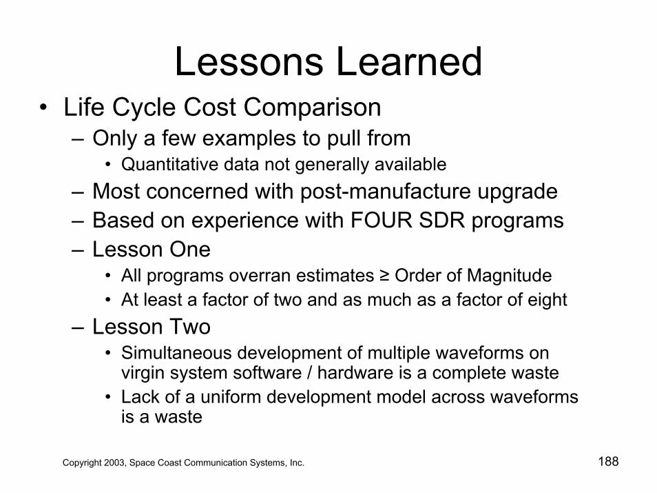
Lessons Learned• Life Cycle Cost Comparison
– Only a few examples to pull from• Quantitative data not generally available
– Most concerned with post-manufacture upgrade– Based on experience with FOUR SDR programs– Lesson One
• All programs overran estimates ≥ Order of Magnitude• At least a factor of two and as much as a factor of eight
– Lesson Two• Simultaneous development of multiple waveforms on
virgin system software / hardware is a complete waste• Lack of a uniform development model across waveforms
is a waste
Copyright 2003, Space Coast Communication Systems, Inc. 188
Lessons Learned• Life Cycle Cost Comparison
– Lesson Three• Infrastructure team not cognizant of Waveform
requirements – Lesson Four
• Once deployed on target hardware don’t abandon simulated development environment
• When hardware upgrade rolls in, must be superbly confident in the behavior of the software in order to isolate those nasty bus glitches, etc.
– Lesson Five• Tried and true legacy software designs generally not
tolerant enough to large fluctuations in CORBA/TCP-IP based communications protocols or multi-user run-time
Copyright 2003, Space Coast Communication Systems, Inc. 189
Lessons Learned• Life Cycle Cost Comparison
– Lesson Six• Some nasty glitches are not the fault of the APPARENT
offender. Quite often task 17 crashes because task 34 overran its stack.
• Heisenberg bugs • A pervasive system-wide design methodology must be
enforced across all development units• No cowboy programmers tolerated in a multi-threaded
environment
– Lesson Seven• It is harder to shut down a waveform cleanly (i.e., no
memory leaks) than it is to bring it up.
Copyright 2003, Space Coast Communication Systems, Inc. 190
Lessons Learned• Development Environments
– Brand New Toys• Everyone wants the latest point-n-click wiz bang tool• Let the kids play with toys• Make your engineers work with tools
– Bells and Whistles and Learning Curves• Cost One: Capitalize the new toy• Cost Two: Capitalize the engineer to learn about it
– Bench-marking• Breaking in a new toy must be specific to its intended
application• Encourage infrastructure folks to interact regularly with the
applications engineers– Stability
• Read your EULA; it’s always your fault, never theirs
Copyright 2003, Space Coast Communication Systems, Inc. 191
Lessons Learned
• Infrastructure– For JTRS includes mature, fully characterized
Core Framework / CORBA / OS combinations– Make/Buy– The Pseudo-Waveform and Confidence Testing– Usually overlaps Waveform Application
Development– Finger pointing: Applications vs. Infrastructure
Copyright 2003, Space Coast Communication Systems, Inc. 192
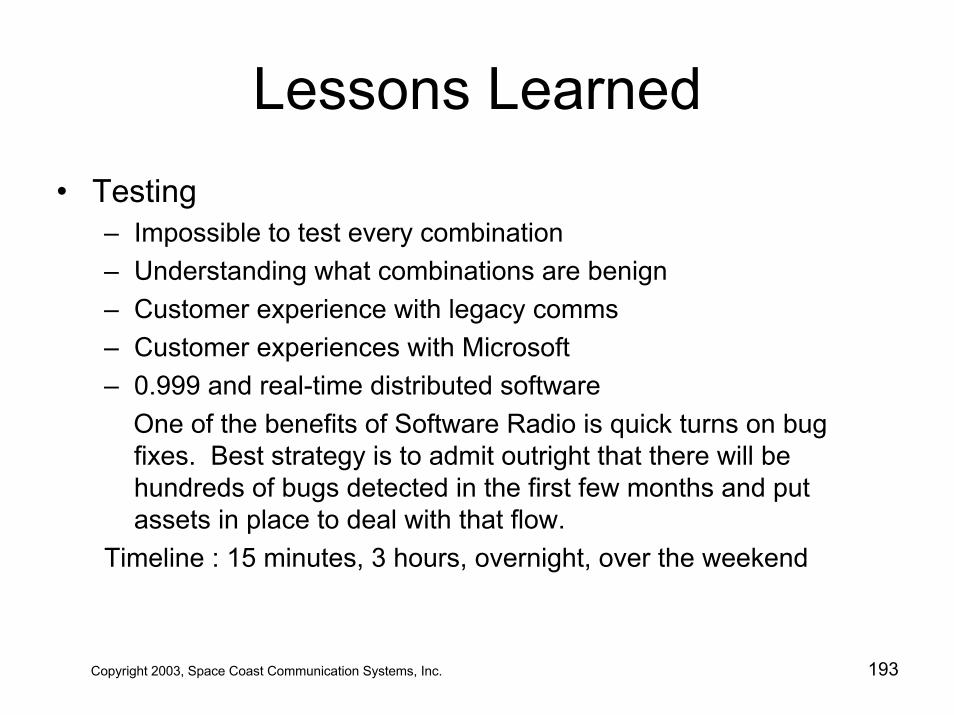
Lessons Learned• Testing
– Impossible to test every combination– Understanding what combinations are benign– Customer experience with legacy comms– Customer experiences with Microsoft– 0.999 and real-time distributed software
One of the benefits of Software Radio is quick turns on bug fixes. Best strategy is to admit outright that there will be hundreds of bugs detected in the first few months and put assets in place to deal with that flow.
Timeline : 15 minutes, 3 hours, overnight, over the weekend
Copyright 2003, Space Coast Communication Systems, Inc. 193
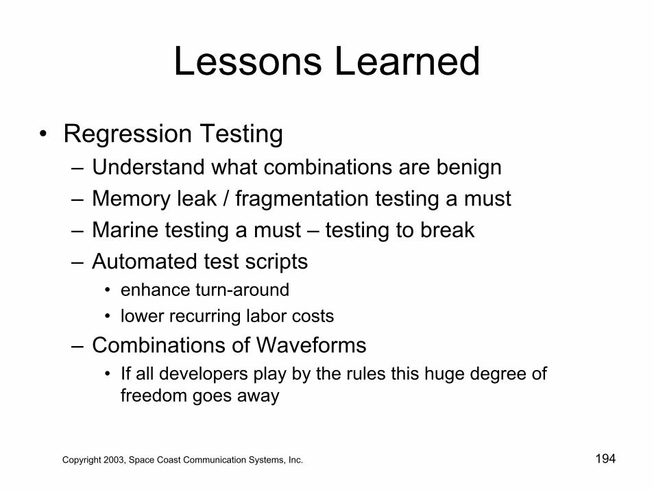
Lessons Learned
• Regression Testing– Understand what combinations are benign– Memory leak / fragmentation testing a must– Marine testing a must – testing to break– Automated test scripts
• enhance turn-around• lower recurring labor costs
– Combinations of Waveforms• If all developers play by the rules this huge degree of
freedom goes away
Copyright 2003, Space Coast Communication Systems, Inc. 194
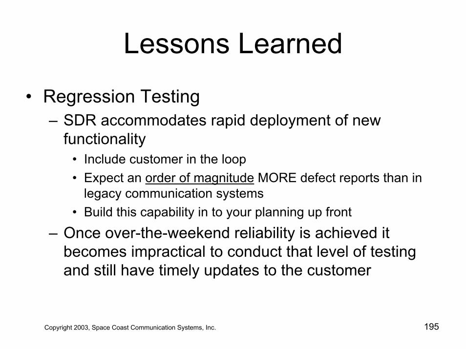
Lessons Learned
• Regression Testing– SDR accommodates rapid deployment of new
functionality• Include customer in the loop• Expect an order of magnitude MORE defect reports than in
legacy communication systems• Build this capability in to your planning up front
– Once over-the-weekend reliability is achieved it becomes impractical to conduct that level of testing and still have timely updates to the customer
Copyright 2003, Space Coast Communication Systems, Inc. 195
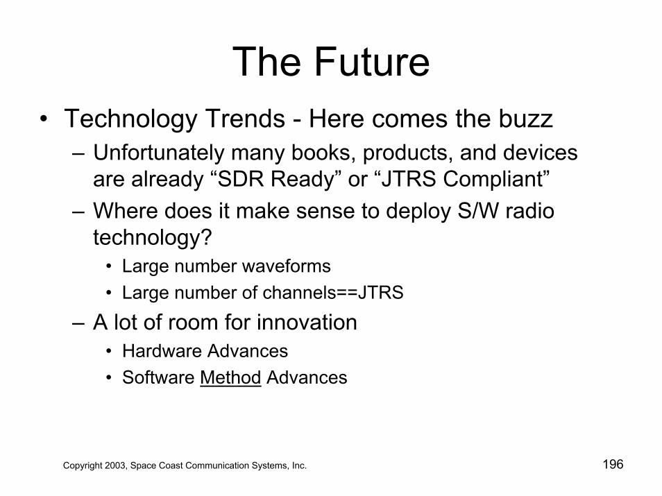
The Future• Technology Trends - Here comes the buzz
– Unfortunately many books, products, and devices are already “SDR Ready” or “JTRS Compliant”
– Where does it make sense to deploy S/W radio technology?
• Large number waveforms• Large number of channels==JTRS
– A lot of room for innovation• Hardware Advances• Software Method Advances
Copyright 2003, Space Coast Communication Systems, Inc. 196
The Future• JTRS has mandated an open systems approach to communication
systems procurement
– Cost per channel is still too high for commercialization– After DoD, Public Safety is next best beneficiary
Copyright 2003, Space Coast Communication Systems, Inc. 197
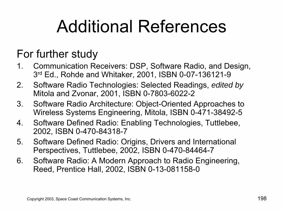
Additional ReferencesFor further study1. Communication Receivers: DSP, Software Radio, and Design,
3rd Ed., Rohde and Whitaker, 2001, ISBN 0-07-136121-92. Software Radio Technologies: Selected Readings, edited by
Mitola and Zvonar, 2001, ISBN 0-7803-6022-2 3. Software Radio Architecture: Object-Oriented Approaches to
Wireless Systems Engineering, Mitola, ISBN 0-471-38492-54. Software Defined Radio: Enabling Technologies, Tuttlebee,
2002, ISBN 0-470-84318-75. Software Defined Radio: Origins, Drivers and International
Perspectives, Tuttlebee, 2002, ISBN 0-470-84464-76. Software Radio: A Modern Approach to Radio Engineering,
Reed, Prentice Hall, 2002, ISBN 0-13-081158-0
Copyright 2003, Space Coast Communication Systems, Inc. 198
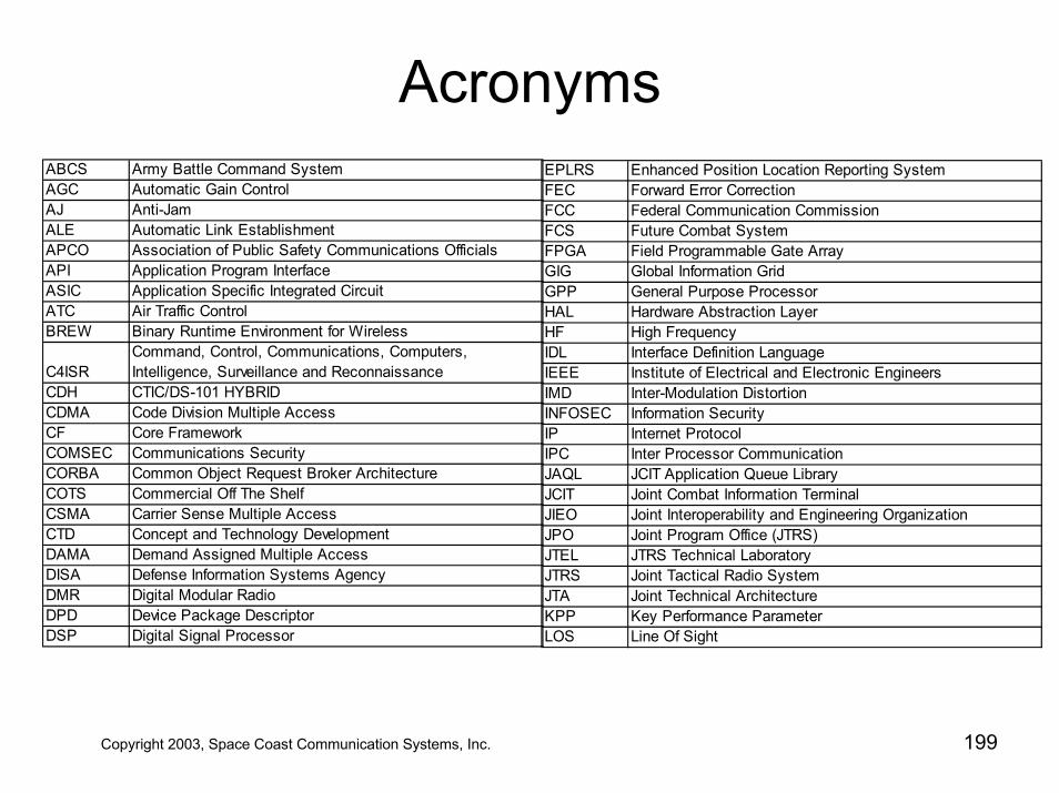
AcronymsABCS Army Battle Command System AGC Automatic Gain ControlAJ Anti-JamALE Automatic Link EstablishmentAPCO Association of Public Safety Communications Officials API Application Program InterfaceASIC Application Specific Integrated CircuitATC Air Traffic ControlBREW Binary Runtime Environment for Wireless
C4ISRCommand, Control, Communications, Computers, Intelligence, Surveillance and Reconnaissance
CDH CTIC/DS-101 HYBRID CDMA Code Division Multiple AccessCF Core FrameworkCOMSEC Communications SecurityCORBA Common Object Request Broker ArchitectureCOTS Commercial Off The ShelfCSMA Carrier Sense Multiple AccessCTD Concept and Technology DevelopmentDAMA Demand Assigned Multiple AccessDISA Defense Information Systems AgencyDMR Digital Modular RadioDPD Device Package DescriptorDSP Digital Signal Processor
EPLRS Enhanced Position Location Reporting SystemFEC Forward Error CorrectionFCC Federal Communication CommissionFCS Future Combat SystemFPGA Field Programmable Gate ArrayGIG Global Information GridGPP General Purpose ProcessorHAL Hardware Abstraction LayerHF High FrequencyIDL Interface Definition LanguageIEEE Institute of Electrical and Electronic EngineersIMD Inter-Modulation DistortionINFOSEC Information SecurityIP Internet ProtocolIPC Inter Processor CommunicationJAQL JCIT Application Queue LibraryJCIT Joint Combat Information TerminalJIEO Joint Interoperability and Engineering OrganizationJPO Joint Program Office (JTRS)JTEL JTRS Technical LaboratoryJTRS Joint Tactical Radio SystemJTA Joint Technical ArchitectureKPP Key Performance ParameterLOS Line Of Sight
Copyright 2003, Space Coast Communication Systems, Inc. 199
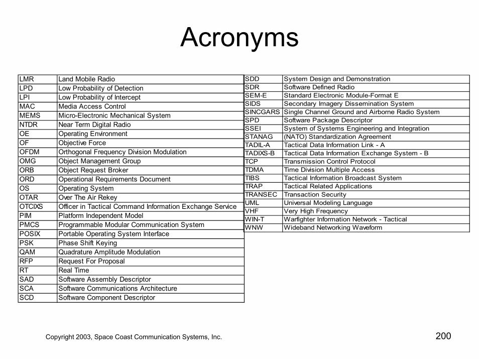
AcronymsLMR Land Mobile RadioLPD Low Probability of DetectionLPI Low Probability of InterceptMAC Media Access ControlMEMS Micro-Electronic Mechanical SystemNTDR Near Term Digital RadioOE Operating EnvironmentOF Objective ForceOFDM Orthogonal Frequency Division ModulationOMG Object Management GroupORB Object Request BrokerORD Operational Requirements DocumentOS Operating SystemOTAR Over The Air RekeyOTCIXS Officer in Tactical Command Information Exchange ServicePIM Platform Independent ModelPMCS Programmable Modular Communication SystemPOSIX Portable Operating System InterfacePSK Phase Shift KeyingQAM Quadrature Amplitude ModulationRFP Request For ProposalRT Real TimeSAD Software Assembly DescriptorSCA Software Communications ArchitectureSCD Software Component Descriptor
SDD System Design and DemonstrationSDR Software Defined RadioSEM-E Standard Electronic Module-Format E SIDS Secondary Imagery Dissemination SystemSINCGARS Single Channel Ground and Airborne Radio SystemSPD Software Package DescriptorSSEI System of Systems Engineering and Integration STANAG (NATO) Standardization AgreementTADIL-A Tactical Data Information Link - ATADIXS-B Tactical Data Information Exchange System - BTCP Transmission Control ProtocolTDMA Time Division Multiple AccessTIBS Tactical Information Broadcast SystemTRAP Tactical Related ApplicationsTRANSEC Transaction SecurityUML Universal Modeling LanguageVHF Very High FrequencyWIN-T Warfighter Information Network - TacticalWNW Wideband Networking Waveform
Copyright 2003, Space Coast Communication Systems, Inc. 200