Embed Size (px)
Citation preview

7/31/2019 Joint - Presentation
http://slidepdf.com/reader/full/joint-presentation 1/46
7/31/2019 Joint - Presentation
http://slidepdf.com/reader/full/joint-presentation 2/46
S.N. Sathiya Narayana
Under the Guidence of
Mr. Suresh Kumar Associate Professor
(Head of the Department – Mech)
7/31/2019 Joint - Presentation
http://slidepdf.com/reader/full/joint-presentation 3/46
To investigate the stress distribution of various
configuration of single lap joint by experimental
analysis .
A parametric study of hybrid joint by varying the three
dimensional parameters of the joint will be carried out
using FEA software.
7/31/2019 Joint - Presentation
http://slidepdf.com/reader/full/joint-presentation 4/46
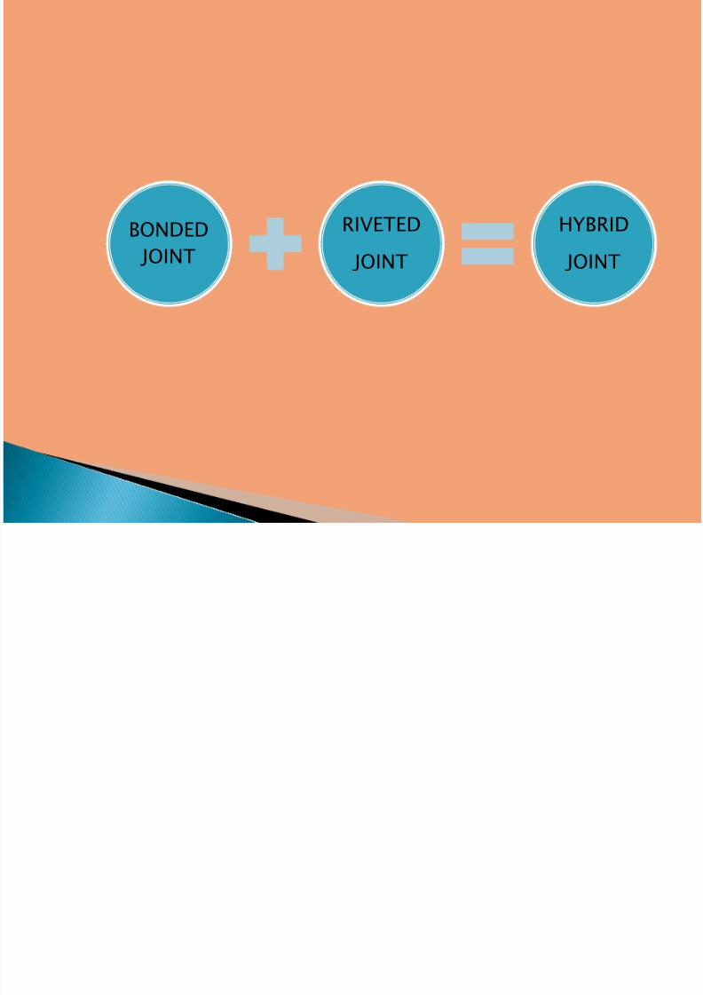
BONDED
JOINT
RIVETED
JOINT
HYBRID
JOINT
7/31/2019 Joint - Presentation
http://slidepdf.com/reader/full/joint-presentation 5/46
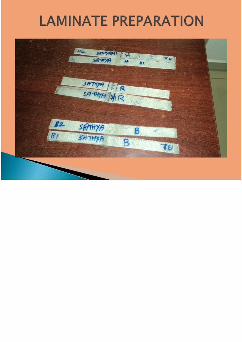
The various Joints were Prepared for analysis and
Experimental work
Such Joints are…
Bonded Joint
Riveted Joint Without Adhesive
Hybrid Joint
7/31/2019 Joint - Presentation
http://slidepdf.com/reader/full/joint-presentation 6/46
Bonded joints can be made by gluing together pre-cured
laminates with the suitable adhesives or by forming jointsduring the manufacturing process, in which case the jointand the laminate are cured at the same time (co-cured).
In general, there are numerous advantages of adhesivebonded joints over the traditional mechanical fastened
joints
These advantages include large bond area for loadtransfer, low stress concentration, smooth externalsurfaces at the joint, less sensitivity to cyclic loading,
time and cost saving, high strength to weight ratio,electrical and thermal insulation, conductivity, corrosionand fatigue resistance, crack retardation, dampingcharacteristic and so on.
7/31/2019 Joint - Presentation
http://slidepdf.com/reader/full/joint-presentation 7/46
Disassembly is impossible withoutcomponent damage.
They can be severely weakened byenvironmental effects.
They require surface preparation.
Joint integrity is difficult to confirm byinspection. Thus ensuring a quality of
bonding has been a challenging task.
7/31/2019 Joint - Presentation
http://slidepdf.com/reader/full/joint-presentation 8/46
The behavior of riveted joints is also influenced byrivet parameters such as rivet size, clamping force,hole size and tolerance. Of these parameters, theclamping force, that is, the force exerted in thethrough – thickness direction by the closing of thefastener, is of critical importance
Advantages of riveted joints are thatNo surface preparation of composite is required.
There are no abnormal inspection problems.
7/31/2019 Joint - Presentation
http://slidepdf.com/reader/full/joint-presentation 9/46
Hybrid joints have a combination of adhesivebonding and mechanical fasteners
The advantages of using a combinedbonded-riveted design apply mainly in arepair situation. It is generally accepted that abonded joint is stronger than a mechanicallyfastened joint and a well-designed bonded
joint is stronger than a hybrid joint.
7/31/2019 Joint - Presentation
http://slidepdf.com/reader/full/joint-presentation 10/46
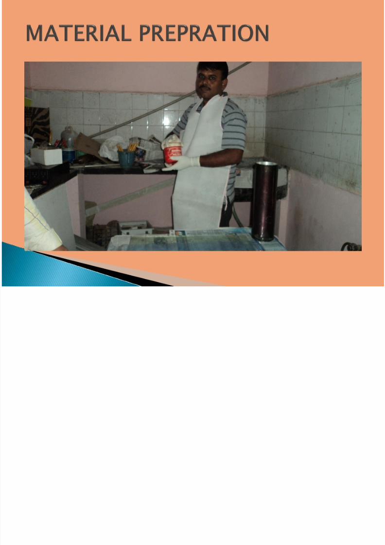
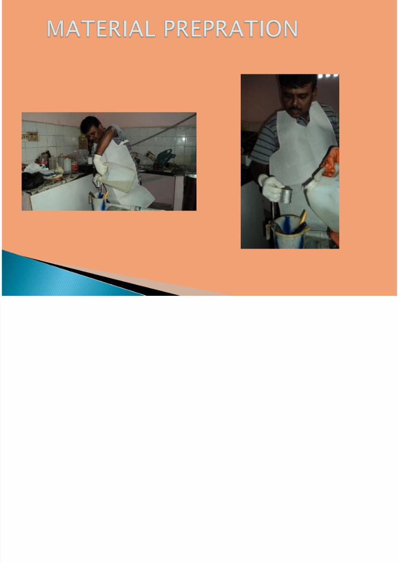
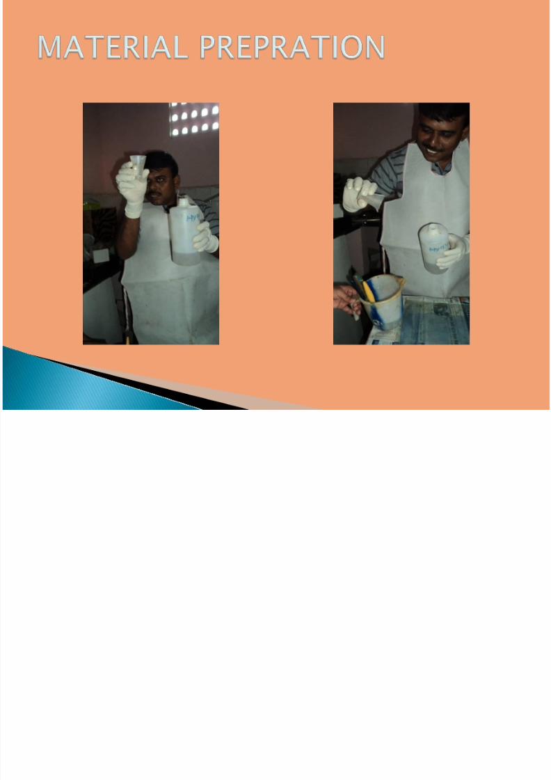
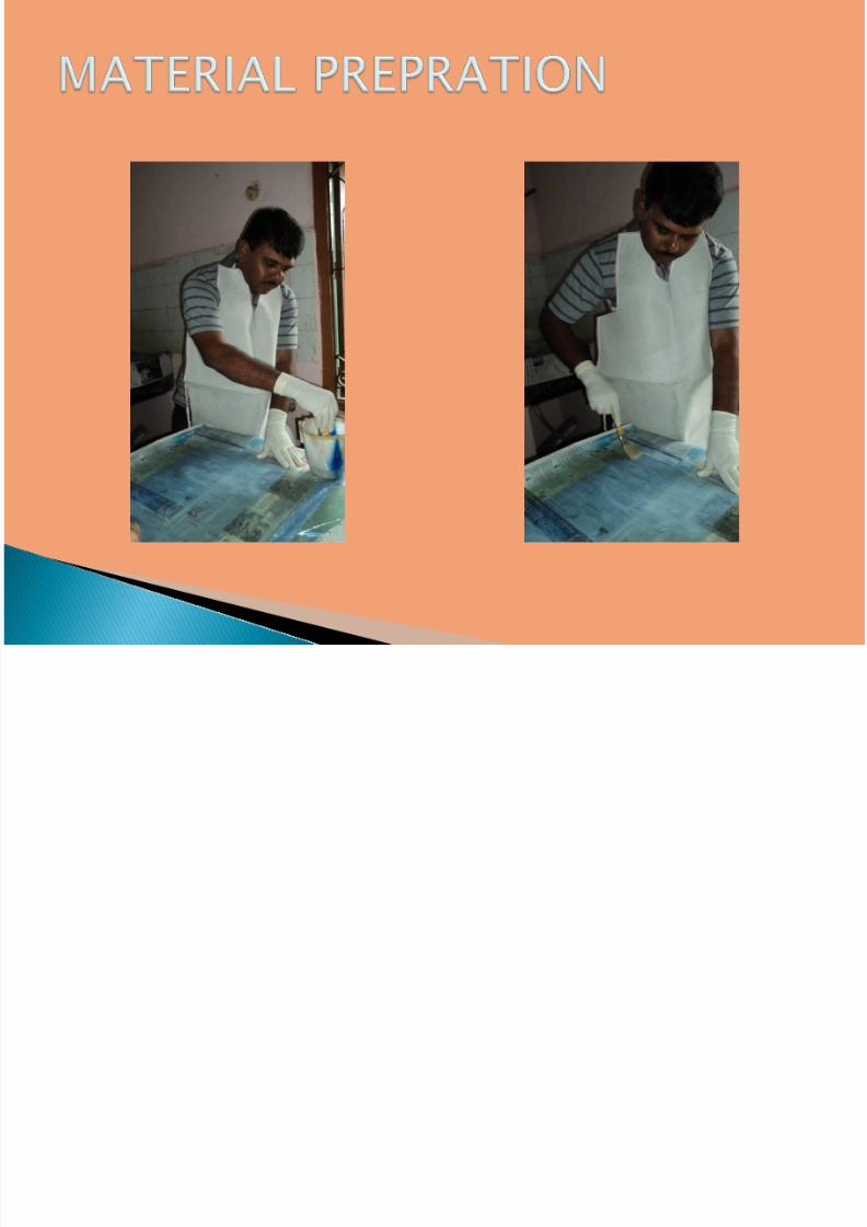
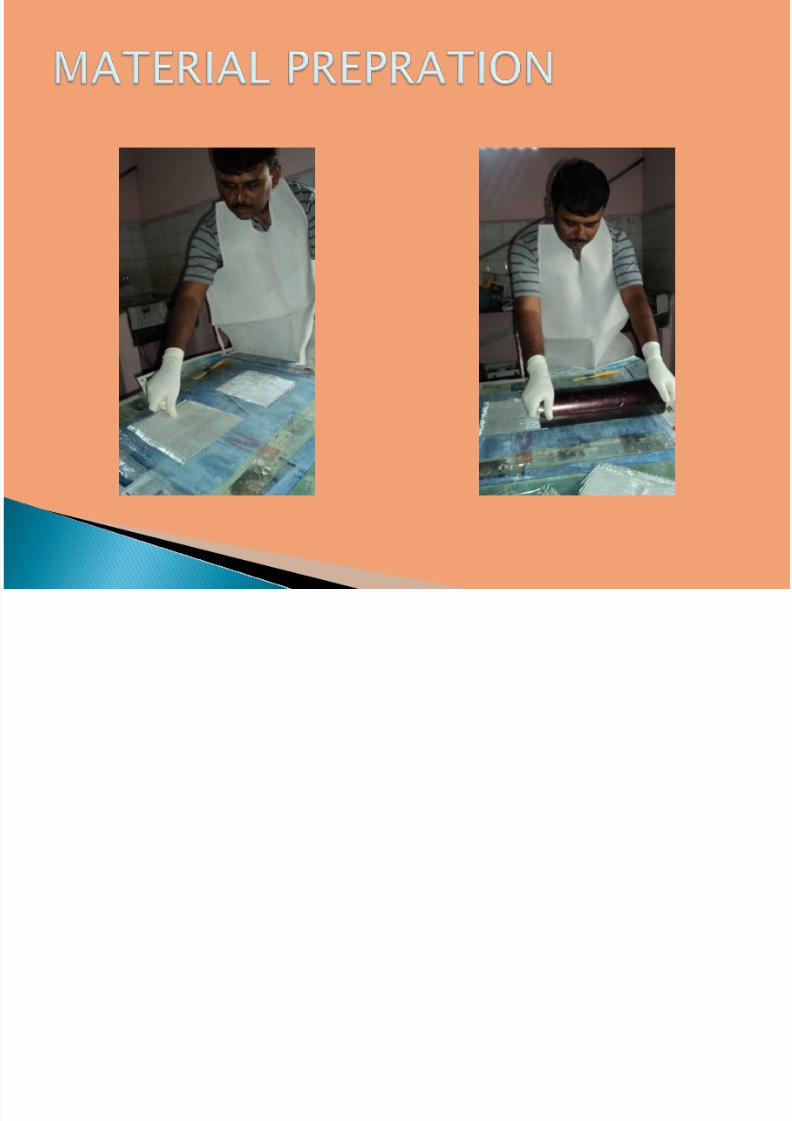
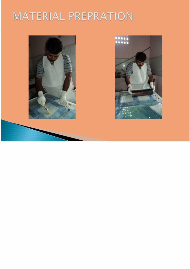
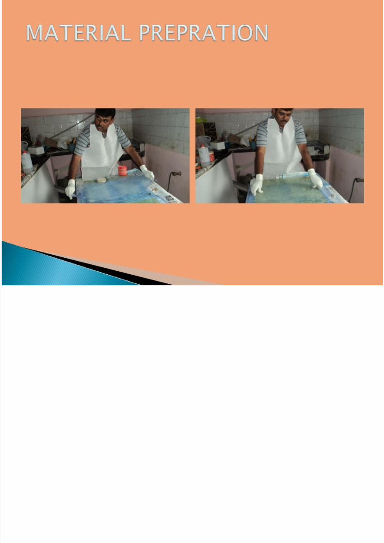
Manual method is adopted. Billet size 300 mm x 300 mm
Thickness of 3.5 mm. (3 layers)
Epoxy–
hardener ratio -> 10:1 Curing time-12 Hrs at Room temperature.
Load applied-10 kg.
7/31/2019 Joint - Presentation
http://slidepdf.com/reader/full/joint-presentation 11/46
7/31/2019 Joint - Presentation
http://slidepdf.com/reader/full/joint-presentation 12/46
7/31/2019 Joint - Presentation
http://slidepdf.com/reader/full/joint-presentation 13/46
7/31/2019 Joint - Presentation
http://slidepdf.com/reader/full/joint-presentation 14/46
7/31/2019 Joint - Presentation
http://slidepdf.com/reader/full/joint-presentation 15/46
7/31/2019 Joint - Presentation
http://slidepdf.com/reader/full/joint-presentation 16/46
7/31/2019 Joint - Presentation
http://slidepdf.com/reader/full/joint-presentation 17/46
7/31/2019 Joint - Presentation
http://slidepdf.com/reader/full/joint-presentation 18/46
7/31/2019 Joint - Presentation
http://slidepdf.com/reader/full/joint-presentation 19/46
7/31/2019 Joint - Presentation
http://slidepdf.com/reader/full/joint-presentation 20/46
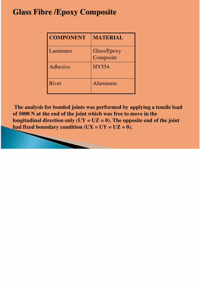
COMPONENT MATERIAL
Laminates Glass/Epoxy
Composite
Adhesive HY554
Rivet Aluminum
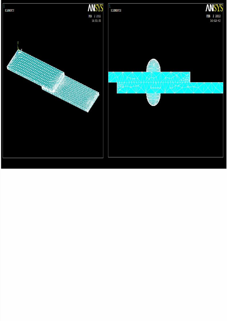
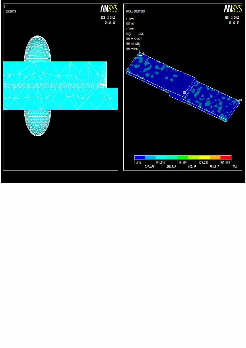
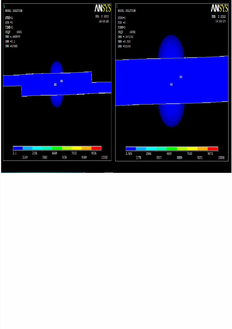
Glass Fibre /Epoxy Composite
The analysis for bonded joints was performed by applying a tensile load
of 5000 N at the end of the joint which was free to move in the
longitudinal direction only (UY = UZ = 0). The opposite end of the joint
had fixed boundary condition (UX = UY = UZ = 0).

7/31/2019 Joint - Presentation
http://slidepdf.com/reader/full/joint-presentation 21/46

7/31/2019 Joint - Presentation
http://slidepdf.com/reader/full/joint-presentation 22/46
7/31/2019 Joint - Presentation
http://slidepdf.com/reader/full/joint-presentation 23/46

7/31/2019 Joint - Presentation
http://slidepdf.com/reader/full/joint-presentation 24/46
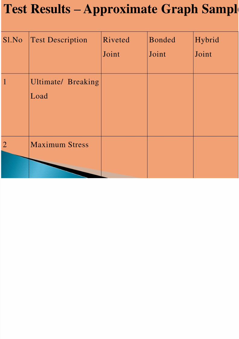
T t R lt A i t G h S l
7/31/2019 Joint - Presentation
http://slidepdf.com/reader/full/joint-presentation 25/46
Sl.No
Test Description
RivetedJoint Bonded
Joint HybridJoint
1
Ultimate/ BreakingLoad
2 Maximum Stress
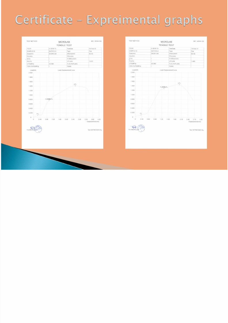
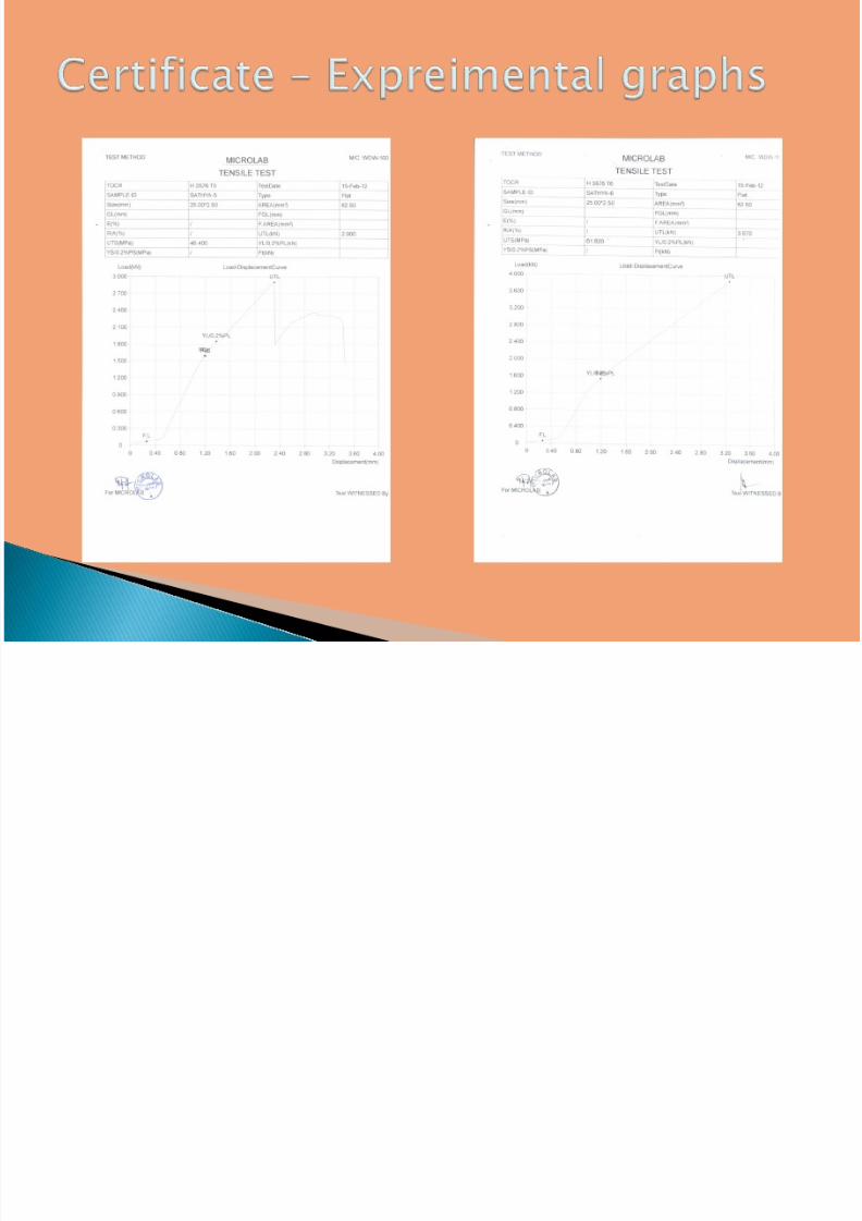
Test Results – Approximate Graph Sampl
7/31/2019 Joint - Presentation
http://slidepdf.com/reader/full/joint-presentation 26/46
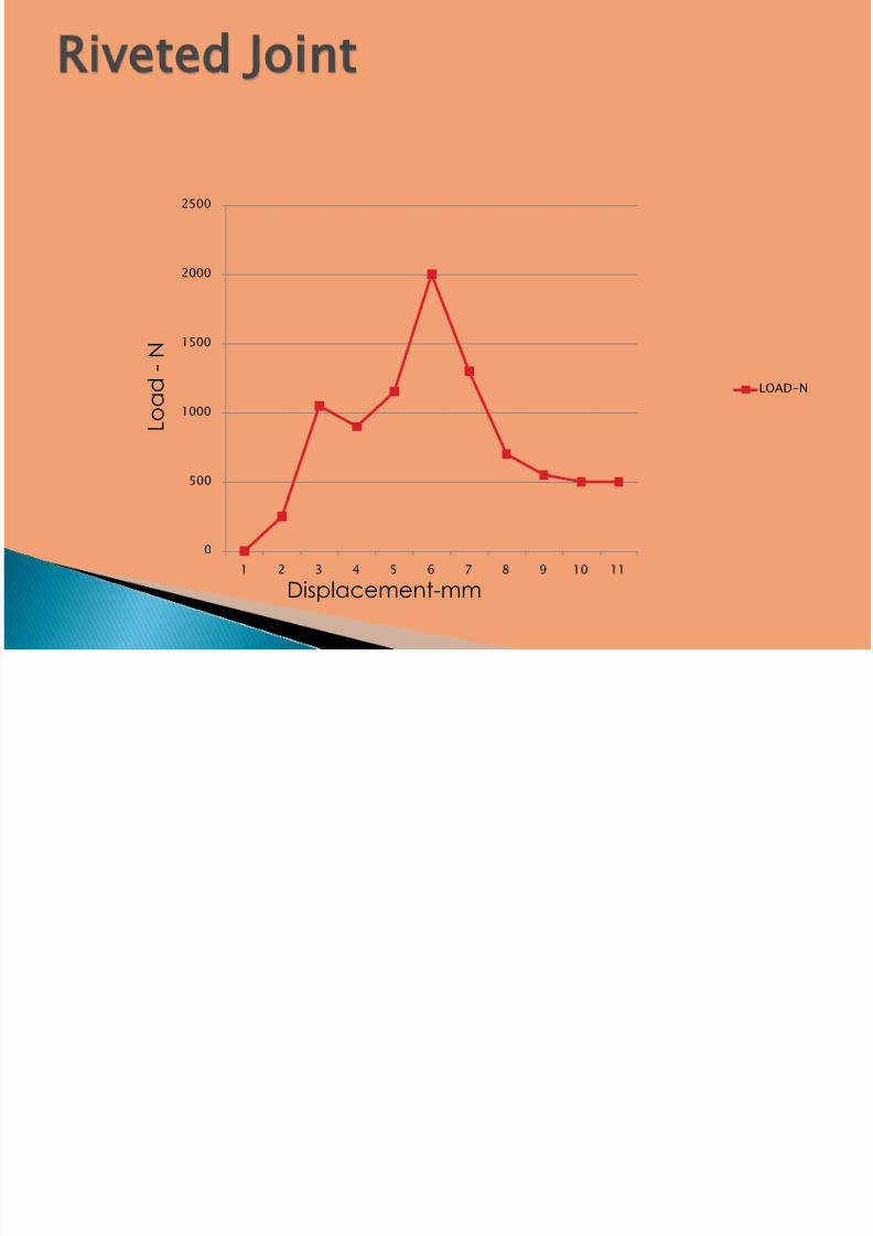
0
500
1000
1500
2000
2500
1 2 3 4 5 6 7 8 9 10 11
LOAD-N
L o a d -
N
Displacement-mm
7/31/2019 Joint - Presentation
http://slidepdf.com/reader/full/joint-presentation 27/46
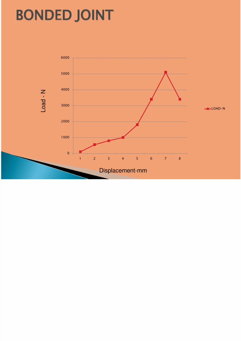
0
1000
2000
3000
4000
5000
6000
1 2 3 4 5 6 7 8
LOAD-N
Displacement-mm
L o a d
- N
7/31/2019 Joint - Presentation
http://slidepdf.com/reader/full/joint-presentation 28/46
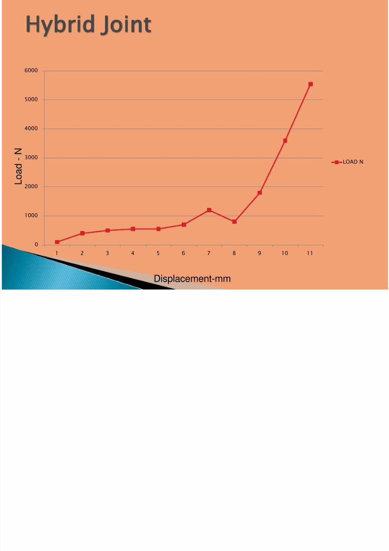
0
1000
2000
3000
4000
5000
6000
1 2 3 4 5 6 7 8 9 10 11
LOAD N
L o a d
- N
Displacement-mm

7/31/2019 Joint - Presentation
http://slidepdf.com/reader/full/joint-presentation 29/46
FINITE ELEMENT
ANALYSIS

7/31/2019 Joint - Presentation
http://slidepdf.com/reader/full/joint-presentation 30/46

7/31/2019 Joint - Presentation
http://slidepdf.com/reader/full/joint-presentation 31/46

7/31/2019 Joint - Presentation
http://slidepdf.com/reader/full/joint-presentation 32/46

7/31/2019 Joint - Presentation
http://slidepdf.com/reader/full/joint-presentation 33/46
7/31/2019 Joint - Presentation
http://slidepdf.com/reader/full/joint-presentation 34/46
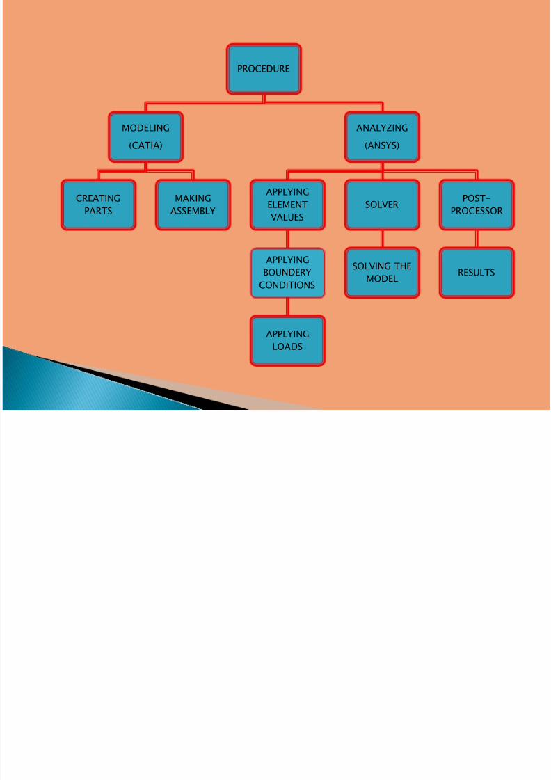
PROCEDURE
MODELING
(CATIA)
CREATINGPARTS
MAKINGASSEMBLY
ANALYZING
(ANSYS)
APPLYINGELEMENT
VALUES
APPLYING
BOUNDERY
CONDITIONS
APPLYING
LOADS
SOLVER
SOLVING THE
MODEL
POST-PROCESSOR
RESULTS
7/31/2019 Joint - Presentation
http://slidepdf.com/reader/full/joint-presentation 35/46
7/31/2019 Joint - Presentation
http://slidepdf.com/reader/full/joint-presentation 36/46
7/31/2019 Joint - Presentation
http://slidepdf.com/reader/full/joint-presentation 37/46
7/31/2019 Joint - Presentation
http://slidepdf.com/reader/full/joint-presentation 38/46
7/31/2019 Joint - Presentation
http://slidepdf.com/reader/full/joint-presentation 39/46
The study can be extended to the failureprediction of the various configurations of joints
using various failure modes and also the progressive
failure analysis (dynamic analysis) can be carried out.
The analysis of hybrid joints can be done using
other criteria so that more progress can be made in
the hybrid joining technology leading to the use of hybrid joints as a primary repair technique.
SCOPE OF THE PROJECT
7/31/2019 Joint - Presentation
http://slidepdf.com/reader/full/joint-presentation 40/46
Thus from the Experimental and Analysis, it
was found that a well-designed hybrid joint is
very efficient when compared to bonded or
riveted joints in the case of repair situation in
aircraft structures.
7/31/2019 Joint - Presentation
http://slidepdf.com/reader/full/joint-presentation 41/46
7/31/2019 Joint - Presentation
http://slidepdf.com/reader/full/joint-presentation 42/46
7/31/2019 Joint - Presentation
http://slidepdf.com/reader/full/joint-presentation 43/46
7/31/2019 Joint - Presentation
http://slidepdf.com/reader/full/joint-presentation 44/46
7/31/2019 Joint - Presentation
http://slidepdf.com/reader/full/joint-presentation 45/46

7/31/2019 Joint - Presentation
http://slidepdf.com/reader/full/joint-presentation 46/46