Embed Size (px)
Citation preview
1
Joint Power and Blocklength Optimization for
URLLC in a Factory Automation Scenario
Hong Ren, Cunhua Pan, Yansha Deng, Maged Elkashlan, and Arumugam
Nallanathan, Fellow, IEEE
Abstract
Ultra-reliable and low-latency communication (URLLC) is one of three pillar applications defined
in the fifth generation new radio (5G NR), and its research is still in its infancy due to the difficulties
in guaranteeing extremely high reliability (say 10−9 packet loss probability) and low latency (say 1 ms)
simultaneously. In URLLC, short packet transmission is adopted to reduce latency, such that conventional
Shannon’s capacity formula is no longer applicable, and the achievable data rate in finite blocklength
becomes a complex expression with respect to the decoding error probability and the blocklength. To
provide URLLC service in a factory automation scenario, we consider that the central controller transmits
different packets to a robot and an actuator, where the actuator is located far from the controller, and the
robot can move between the controller and the actuator. In this scenario, we consider four fundamental
downlink transmission schemes, including orthogonal multiple access (OMA), non-orthogonal multiple
access (NOMA), relay-assisted, and cooperative NOMA (C-NOMA) schemes. For all these transmission
schemes, we aim for jointly optimizing the blocklength and power allocation to minimize the decoding
error probability of the actuator subject to the reliability requirement of the robot, the total energy
constraints, as well as the latency constraints. We further develop low-complexity algorithms to address
the optimization problems for each transmission scheme. For the general case with more than two
devices, we also develop a low-complexity efficient algorithm for the OMA scheme. Our results show
that the relay-assisted transmission significantly outperforms the OMA scheme, while NOMA scheme
performs well when the blocklength is very limited. We further show that the relay-assisted transmission
has superior performance over the C-NOMA scheme due to larger feasible region of the former scheme.
I. INTRODUCTION
The fifth-generation (5G) networks are envisaged to support three pillar use cases: enhanced
mobile broadband (eMBB), massive machine type communication (mMTC), and mission-critical
H. Ren, C. Pan, M. Elkashlan, and A. Nallanathan are with School of Electronic Engineering and Computer Science, QueenMary University of London, London, E1 4NS, U.K. (Email: h.ren, c.pan, maged.elkashlan, [email protected]). Y. Dengis with the Department of Informatics, Kings College London, London WC2R 2LS, U.K. (e-mail: [email protected]).
arX
iv:1
911.
1305
0v1
[ee
ss.S
P] 2
9 N
ov 2
019
2
internet of things (IoT) [1]. Extensive research has focused on eMBB and mMTC, but the research
on mission-critical IoT is still in its infancy [2]–[6]. The applications of mission-critical tasks
include factory automation (FA), autonomous driving, remote surgery, smart grid automation,
unmanned aerial vehicles (UAVs) control information delivery [7], which require ultra reliable
and low latency communication (URLLC) [8]–[10]. For example, in Industrial 4.0 [11], wired
connection will be replaced by wireless transmission to enhance the flexibility and reduce the
infrastructure cost. This change imposes challenging requirements on the wireless transmission in
terms of latency and reliability [12]. For mission-critical tasks in FA, the transmission duration
is expected to be lower than 100 µs to allow processing delays during queuing, scheduling,
backhaul transmission, and propagation [13], while guaranteeing the packet error probability of
10−9.
In conventional human-to-human (H2H) communications, the transmission delay is relatively
long (say 20-30 ms) and the packet size is large (say 1500 bytes), thus Shannon’s capacity can be
served as a tight upper bound of the achievable data rate due to the law of large numbers [14]. In
contrast, in URLLC, the packet size should be extremely low (say 20 bytes) to support the low-
latency transmission [13]. In this case, Shannon’s capacity formula is no longer applicable as the
law of large numbers is not valid. Thus, the achievable data rate under short blocklength needs
to be retreated. In [15], the achievable data rate in finite blocklength regime has been derived
as a complicated function of the signal-to-noise (SNR), the blocklength, and the decoding error
probability.
Recently, extensive research attention has been devoted to the short packet transmission (SPT)
design [16]–[26]. In particular, the frame structure is designed in [16] for SPT, where their results
showed that it is beneficial to group multiple messages from some users into a single packet
based on approximations from finite blocklength information theory. In [17], She et al. studied
the network available range maximization problem by dynamically selecting the transmission
modes between device-to-device (D2D) and cellular links. The non-asymptotic upper and lower
bounds on the coding rate for SPT over a Rician memoryless block-fading channel were derived
in [18] under a given packet error probability requirement. The overall error probability of
relay-assisted transmission under finite blocklength was derived in [19] under the assumption
of perfect channel state information (CSI). They further extended this model to the quasi-static
Rayleigh channels where only the average CSI is available at the source in [20], as well as
to the two-way amplify-and-forward relay network in [21]. Recently, the delay and decoding
3
error probability were analyzed in [22] for simultaneous wireless information and power transfer
(SWIPT) relay-assisted system, where the relay first harvests energy from the source and then
uses the harvested energy to forward the source’s information to the destination node.
The aforementioned studies [16]–[22] mainly focused on the performance analysis of finite
blocklength transmission. In order to design a practical URLLC system, it is imperative to
intelligently optimize the resource allocation including blocklength and power allocation under
the given error probability and latency requirements. Unfortunately, the achievable coding rate
expression is neither convex nor concave with respect to the blocklength and the transmit power,
which brings the difficulty in obtaining the globally optimal solution [5]. This motivates the recent
studies in resource allocation for the SPT in [23]–[27]. Specifically, the average throughput and
the max-min throughput optimization under the latency constraint was solved via the exhaustive
search method with high complexity in [23]. Sun et al. in [24] considered the SPT for a two-
user downlink non-orthogonal multiple access (NOMA) system, with an aim to maximize the
throughput of user 1 subject to the throughput requirements for user 2. Note that the decoding
error probability requirement has not been considered in [23] and [24], and the throughput
is less important in URRLC as only control signals or measurement data with small packet
size are transmitted in URLLC. In [25], She et al. jointly optimized the uplink and downlink
transmission blocklengths to minimize the required total bandiwidth based on statistical channel
state information (CSI). However, the optimization is based on the simplified expression of the
rate for SPT, which cannot accurately characterize the relationship between the decoding error
probability and blocklength. In addition, several approximations are involved in the derivation of
the decoding error probability for each user due to the fact that only statistical CSI is available.
Most recently, Hu et al. [26] considered SWIPT in relay-assisted URLLC systems, where the
SWIPT parameters and blocklength are jointly optimized to maximize the reliability performance.
However, the decoding error probability at the relay cannot be guaranteed and the power is
assumed to be fixed in [26]. Most recently, in [27] we jointly optimize the blocklength and
unmanned aerial vehicle’s (UAV’s) location to minimize the decoding error probability while
guaranteeing the latency requirement and decoding error probability target. However, the power
allocation was not considered. Furthermore, the optimization over UAV’s location is obtained
by observing the curve of the second-order derivative of the objective function over location
variable without strict proof.
In this paper, we consider a typical mission-critical scenario (i.e., a FA scenario), where the
4
central controller needs to transmit a certain amount of different data to two devices within
a given transmission time and under a very low packet error probability. One device named
actuator is located far away from the controller, while the other device named robot can move
between the controller and the actuator. We consider four fundamental transmission schemes,
namely, orthogonal multiple access (OMA), NOMA, relay-assisted transmission and cooperative
NOMA (C-NOMA). In this scenario, we aim for jointly optimizing the blocklength and the
transmit power of these two devices to minimize the decoding error probability for the actuator
while guaranteeing the decoding error probability for the robot, taking into account the energy
and blocklength constraints, which were not considered in [24]–[26] and new methods needs to
be developed. The main contributions of this paper are summarized as follows:
1) For the OMA scheme, we first prove that both the decoding error probability and energy
constraints hold with equality at the optimal point, and then propose a novel iterative
algorithm to obtain tight lower and upper bounds of the blocklength to reduce the search
complexity. A low-complexity algorithm is proposed to find the globally optimal solution
of transmit power. For the case of more than two devices, we also develop a novel
low-complexity algorithms to find the suboptimal solution of the optimization problem.
2) For the NOMA scheme, the search set of blocklength is first derived to reduce the search
complexity. In contrast to the OMA case, the decoding error probability function for each
given blocklength in the NOMA case is non-continuous with respect to the transmit power,
which complicates the optimization problem. Fortunately, we rigorously proved that the
decoding error probability holds with equality at the optimal point, such that the one-
dimensional line search algorithm can be used to find the optimal solution. We also provide
a sufficient condition when the decoding error probability function is a convex function,
which facilitates the application of a low-complexity bisection search method.
3) For the relay-assisted scheme, we also adopt the iterative algorithm to reduce the search
complexity of blocklength. Unlike the OMA and NOMA schemes, the decoding error
probability constraint of relay-assisted transmission does not hold with equality. To resolve
this issue, we fix the blocklength, such that the original optimization problem is reduced
to a one-dimension search optimization problem.
4) For the C-NOMA scheme, we adapt the iterative algorithm to reduce the search complexity
of blocklength, and then one-dimension search is proposed to find the optimal transmit

5
power. For the special case, low-complexity bisection search method is applied.
5) To compare the performance of our proposed four transmission schemes, we perform exten-
sive simulation results, which show that the relay-assisted scheme significantly outperforms
the other three schemes for most times in terms of both the decoding error probability and
the network availability. Our results demonstrate the effectiveness of relaying transmission
in enhancing the reliability performance in the industrial automation scenario.
The remainder of this paper is organized as follows. In Section II, the system model and the
problem formulation are provided. In Section III, the transmission scheme is presented. The
general case with more than two devices is considered in Section IV. Simulation results and
analysis are presented in Section V. Finally, Section VI concludes the paper.
II. SYSTEM MODEL
A. System model
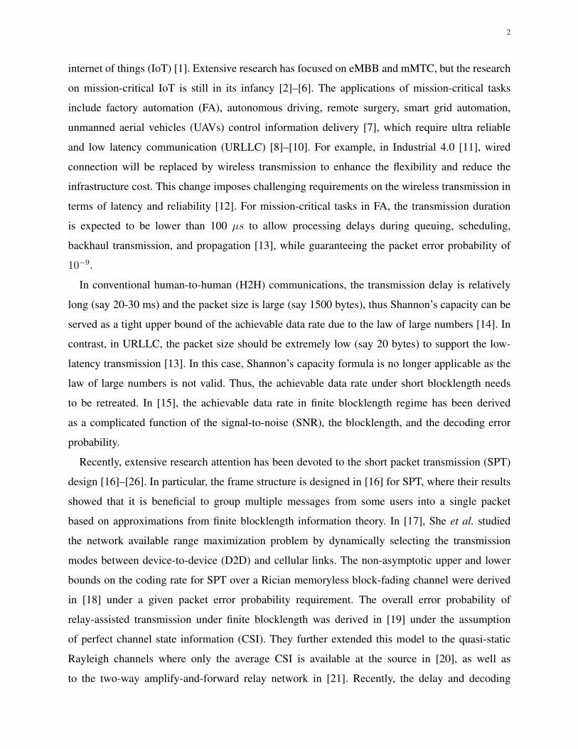
Consider a downlink communication in one factory, where a central controller serves a robot
and an actuator as shown in Fig. 1. The robot is assumed to be located in the vicinity of the
controller, and the actuator is far away from the controller. Both the robot and the actuator are
equipped with a single antenna. The controller needs to transmit two small packets to the two
devices. The packet sizes for the actuator and the robot are assumed to be the same, and are
denoted as D bits.
The transmission of these two packets is subject to a latency constraint, i.e., the transmission
has to finish within M symbols or channel uses. The transmission time corresponds to tmax =
MTs seconds, where Ts is the symbol duration that is equal to 1/B with B as the system
bandwidth. For the applications with URLLC requirement, short frame structure is adopted and
the end-to-end delay should be kept within 1 ms [8], which is much shorter than the channel
coherence time. Hence, the channels are quasi-static fading and remain constant during the whole
transmission. The channel fading coefficients from the central controller to the robot and the
actuator are denoted as h1 and h2, respectively. The channel fading coefficient between the robot
and the actuator is denoted as h3. We also assume that these channels are perfectly known at the
controller, and the total energy consumption of the system should be below Etot Joule. Since
we have assumed that the actuator is far away from the controller, the channel power gain∣∣∣h2
∣∣∣2is very small.
6
1h
RobotActuator
2h
3h
Controller
Fig. 1: Illustration of a Factory Automation Scenario.
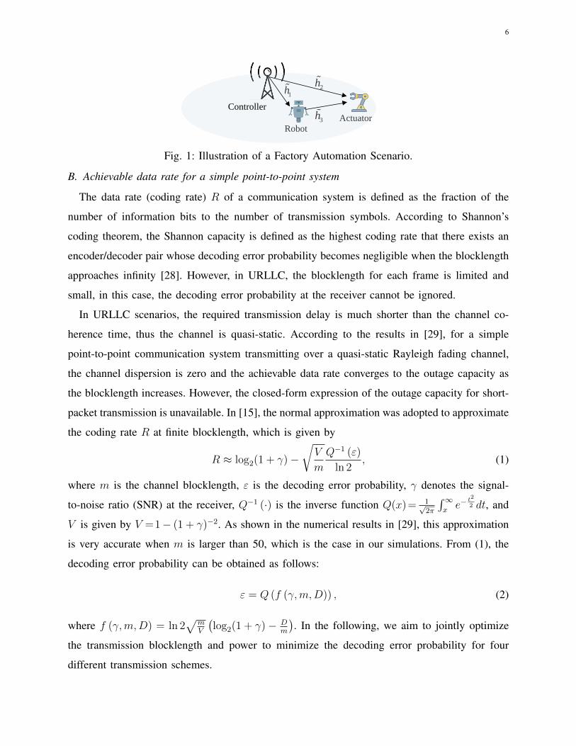
B. Achievable data rate for a simple point-to-point system
The data rate (coding rate) R of a communication system is defined as the fraction of the
number of information bits to the number of transmission symbols. According to Shannon’s
coding theorem, the Shannon capacity is defined as the highest coding rate that there exists an
encoder/decoder pair whose decoding error probability becomes negligible when the blocklength
approaches infinity [28]. However, in URLLC, the blocklength for each frame is limited and
small, in this case, the decoding error probability at the receiver cannot be ignored.
In URLLC scenarios, the required transmission delay is much shorter than the channel co-
herence time, thus the channel is quasi-static. According to the results in [29], for a simple
point-to-point communication system transmitting over a quasi-static Rayleigh fading channel,
the channel dispersion is zero and the achievable data rate converges to the outage capacity as
the blocklength increases. However, the closed-form expression of the outage capacity for short-
packet transmission is unavailable. In [15], the normal approximation was adopted to approximate
the coding rate R at finite blocklength, which is given by
R ≈ log2(1 + γ)−√V
m
Q−1 (ε)
ln 2, (1)
where m is the channel blocklength, ε is the decoding error probability, γ denotes the signal-
to-noise ratio (SNR) at the receiver, Q−1 (·) is the inverse function Q(x)= 1√2π
∫∞xe−
t2
2 dt, and
V is given by V =1− (1 + γ)−2. As shown in the numerical results in [29], this approximation
is very accurate when m is larger than 50, which is the case in our simulations. From (1), the
decoding error probability can be obtained as follows:
ε = Q (f (γ,m,D)) , (2)
where f (γ,m,D) = ln 2√
mV
(log2(1 + γ)− D
m
). In the following, we aim to jointly optimize
the transmission blocklength and power to minimize the decoding error probability for four
different transmission schemes.
7
III. TRANSMISSION SCHEMES
In this section, we aim for designing efficient resource allocation algorithms to minimize the
decoding error probability of the actuator under three sets of constraints: 1) the packets for robot
and actuator need to be transmitted within M symbols; 2) the robot should satisfy its reliability
requirement; 3) the total consumed energy should be kept within Etot. The OMA, NOMA,
relay-assisted transmission, and C-NOMA transmission schemes are studied in the following
subsections.A. OMA transmission
The OMA scheme is the simplest transmission scheme, where the controller serves the robot
and the actuator in two different orthogonal channel uses or blocklengths. In detail, the controller
transmits signal x1 to the robot with m1 blocklength. Due to this orthogonal property, the received
signal at the robot can be represented asy1 =
√p1h1x1 + n1, (3)
where p1 is the transmit power of the robot, n1 is the zero-mean additive complex white Gaussian
noise (AWGN) with variance σ21 , x1 carries information knowledge for the robot with packet
size D. Hence, the coding rate at the robot is given by D/m1.
From (3), the received signal to noise ratio (SNR) at the robot is given by
γ1 = p1h1, (4)
where h1 = |h1|2/σ21 denotes the normalized channel gain from the controller to the robot. Then,
according to (2), the decoding error probability of x1 at the robot is given by
ε1 = Q (f (γ1,m1, D)) . (5)
The controller transmits signal x2 to the actuator with blocklength equal to m2. The corre-
sponding error probability at the actuator is derived as
ε2 = Q (f (γ2,m2, D)) , (6)
where γ2 = p2h2 with p2 as the transmit power of the actuator and h2 = |h2|2/σ22 as the
normalized channel gain for the actuator. Without loss of generality (w.l.o.g.), we assume that
in this paper the robot has higher normalized channel gain than the actuator, i.e., h1 > h2.
The resource allocation problem for the OMA transmission can be formulated as:min
{m1,m2,p1,p2}ε2 (7a)
s.t. ε1 ≤ εmax1 , (7b)
m1p1 +m2p2 ≤ Etot, (7c)
m1 +m2 ≤M, (7d)
m1,m2 ∈ Z, (7e)
8
where constraint in (7b) is the decoding error probability requirement of the robot, constraint
(7c) ensures the system total energy consumption is within a budget Etot = EtotTs, (7d) is the
constraint on the latency constraint, and constraint (7e) ensures that the blocklength for each
transmission phase is integer with Z denoting the positive integer set. The maximum decoding
error probability εmax1 is assumed to be much less than 0.1 to ensure the stringent reliability
requirement, and this assumption holds for the remaining transmission schemes. As a result, ε1
should be smaller than 0.1. Then, the inequality Dm1
< log2(1 + γ1) should hold.
To solve the optimization problem in (7), we first provide the following lemma.
Lemma 1: Constraints (7b) and (7c) hold with equality at the optimum solution.
Proof : Please see Appendix A.
With m1 and m2 to be integers, the exhaustive search method can be used to find the optimal
solution. To reduce the search complexity when M is large, we shorten the search range of m1
and m2. In the following, we aim to derive the bounds of m1 and m2.
1) The upper and lower bounds of m1 and m2: Since εmax1 is assumed to be a very small
value that is much smaller than 10−1, a necessary condition for constraint (7b) to hold is that
log2 (1 + p1h1) > D/m11, which leads to
p1 >(
2Dm1 − 1
)/h1. (8)
On the other hand, based on the energy constraint (7c), we have: p1 < Etot/m1. Thus, the
blocklength allocation of the robot m1 should satisfy the following inequality:
Etot >m1
h1
(2Dm1 − 1)
∆= g(m1). (9)
To investigate the properties of g(m1), the first-order and second-order derivatives of function
g(m1) w.r.t. m1 are give byg′(m1) = 2
Dm1 − 1− ln 2 · D
m1
2Dm1 , (10)
g′′(m1) = (ln 2)2 · D2
m31
2Dm1 ≥ 0. (11)
Thus, g′(m1) is a monotonically increasing function of m1, and we have
g′(m1) ≤ limm1→+∞
g′(m1) = 0. (12)
Hence, function g(m1) is a monotonically decreasing function of m1. Then, we can find the
lower bound of m1 that satisfies the inequality (9) which is denoted as mlb(0)1 , and m1 should
be no smaller than mlb(0)1 , i.e., m1 ≥ m
lb(0)1 . Similarly, for practical applications, the decoding
1 This can be proved as follows: ε1 = Q (f (γ1,m1, D)) < εmax1 < 0.5 = Q (0). Since Q-function is a decreasing function,
we have f (γ1,m1, D) > 0. By substituting the expression of f (γ1,m1, D), the proof is complete.

9
error probability of the actuator ε2 should be very small, e.g., much lower than 0.5. In this case,
the inequality log2 (1 + p2h2) > D/m2 should hold, which leads to
p2 >(
2Dm2 − 1
)/h2. (13)
By using the inequality m2 ≤M −mlb(0)1 , we have
m2p2 ≥m2
h2
(2
Dm2 − 1
)≥ M −mlb(0)
1
h2
(2
D
M−mlb(0)1 − 1
)∆= A(0). (14)
By using constraint (7c), we have
Etot − A(0) >m1
h1
(2
Dm1 − 1
). (15)
By using (15), the updated lower bound of m1 can be obtained, and denoted as mlb(1)1 . Similar
to (14), we can obtain A(1) by substituting mlb(1)1 into mlb(0)
1 , and the lower bound of m1 can be
obtained by using (15), where A(0) is replaced by A(1), and the updated lower bound is denoted
as mlb(2)1 . Repeat the above procedure until mlb(n)
1 = mlb(n−1)1 or mlb(n)
1 = M − mlb(0)2 . Then,
denote the final lower bound of m1 as mlb1 .
This procedure is proved to converge as follows. By using A(0) ≥ 0 and comparing (9) and
(15), we can obtain mlb(1)1 ≥ m
lb(0)1 , and thus A(1) ≥ A(0), which leads to mlb(2)
1 ≥ mlb(1)1 . Hence,
the sequence of the lower bound mlb(n)1 is monotonically increasing. Furthermore, the sequence
is upper bounded by M − mlb(0)2 . As a result, the sequence generated by the above iterative
procedure is guaranteed to converge.
By using the similar iterative procedure, we can also obtain the lower bound of m2, which is
denoted as mlb2 . As a result, the search region of m1 is given by mlb
1 ≤ m1 ≤ (M−mlb2 )
∆= mub
1 .
For each given m1, we need to find the search range of m2, which is detailed as follows. The
optimal p1 can be obtained by solving the equation ε1 = εmax1 with given m1, which is denoted
as p∗1. The solution can be readily obtained by using the bisection search method due to the fact
that ε1(p1) is a monotonically decreasing function of p1. Then, we have
Etot −m1p∗1 = m2p2 ≥
m2
h2
(2
Dm2 − 1
). (16)
Hence, the lower bound of m2 with given m1 (denoted as mlb2 (m1)) can be obtained from
(16), which is the minimum integer that satisfies (16). Obviously, the upper bound of m2 with
given m1 is M −m1. Hence, the search region of m2 is given by mlb2 (m1) ≤ m2 ≤ (M −m1).
10
2) Algorithm to solve Problem (7): Based on the above analysis, the algorithm to solve
Problem (7) is given in Algorithm 1. The main idea can be summarized as follows. For each
given integer value of m1 that satisfies mlb1 ≤ m1 ≤ mub
1 , we calculate the value of ε1 when p1 is
set as Etot/m1. If ε1 > εmax1 , then the value of m1 is not feasible, and we increase the value of m1
by one and continue to check the updated m1. Otherwise, we apply the bisection search method
to find the value of p1 such that ε1 = εmax1 due to the monotonically decreasing property of
decoding error probability ε1 w.r.t. p1 [24]. By using Lemma 1, we have m2p2 = Etot −m1p1.
The search range of m2 is given by mlb2 (m1) ≤ m2 ≤ M − m1. For each given m2, the
corresponding p2 is given by p2 = (Etot − m1p1)/m2, and we can calculate the value of ε2.
For each feasible m1, we can find the optimal solutions for m2 and p2 that yield the minimum
value of ε2, respectively. At last, we check all feasible m1 in the range of mlb1 ≤ m1 ≤ mub
1 ,
and choose the final globally optimal solution.
Algorithm 1: Algorithm for Problem (7)Input : h1, h2, D,M, εmax
1 , EtotOutput: p?1, p?2,m?
1,m?2
1 Apply the iterative procedure to calculate mlb1 ,m
ub1 and mlb
2 ;2 for m1 = mlb
1 : mub1 do
3 Set p1 = Etot/m1, and calculate the value of ε1.4 if ε1 > εmax
1 then5 The current m1 is not feasible, and return to the next m1;6 else7 Use (16) to find the lower bound of m2, denoted as mlb
2 (m1). Apply the bisectionsearch method to find the value of p1 such that ε1 = εmax
1 ;8 for m2 = mlb
2 (m1) : M −m1 do9 Calculate p2 = (Etot −m1p1)/m2, and the value of ε2, denoted as ε2(m1,m2).
10 end11 Given m1, find the blocklength m2 with the minimum value of ε2(m1,m2):
m#2
∣∣∣m1
= arg minmlb
2 ≤m2≤M−m1
ε2 (m1,m2) .
12 end13 end14 Return m?
1 = arg minmlb
1 ≤m1≤mub1
ε2
(m1, m
#2
∣∣∣m1
),m?
2 = m#2
∣∣∣m?
1
and the corresponding p?1 and p?2.
3) Special case of Problem (7): In steps 8-10 of Algorithm 1, one has to calculate the value
of ε2 for each m2, which may incur high complexity. In this subsection, we consider one special
case when the SNR value γ is very high, i.e., γ � 1. In this case, V in (2) can be approximated
as one, i.e., V ≈ 1 2. The optimization problem in this special case can be efficiently solved.
2 In general, when γ > 20 dB, the value of V is larger than 0.99, which can be approximated as one.
11
Specifically, the decoding error probability in (2) can be approximated as
ε = Q(f (γ,m,D)
), (17)
where f (γ,m,D) = ln 2√m(log2(1 + γ)− D
m
).
For given m1 and p1, the product of m2 and p2 should satisfy m2p2 = Etot − m1p1∆= E2
according to Lemma 1. Then, the original problem defined in (7) can be transformed to the
following optimization problem:
minmlb
2 ≤m2≤M−m1,m2∈ZQ(f (γ2,m2, D)
). (18)
Since Q-function is a decreasing function, the above problem is equivalent to the following
problem by substituting p2 = E2/m2 into it as
maxmlb
2 ≤m2≤M−m1,m2∈Zln 2√m2
(log2
(1+
E2h2
m2
)−Dm2
). (19)
To solve the above problem, we first relax the integer variable m2 to a continuous variable,
and defineg(m2)
∆=√m2
(log2
(1 +
E2h2
m2
)− D
m2
). (20)
In the following theorem, we provide a sufficient condition for g(m2) to be a concave function.
Theorem 1: g(m2) is a concave function when E2h2M−m1
≥ e−1, where e is the natural constant.
Proof : Please see Appendix B.
When the condition in Theorem 1 is satisfied, Problem (19) is a convex optimization problem.
If g′(mlb2 ) ≤ 0, the optimal m2 is given by m2 = mlb
2 . If g′(M − m1) ≥ 0, the optimal m2
is m2 = M − m1. Otherwise, the optimal m∗2 satisfies g′(m2) = 0, and the low-complexity
bisection search method can be used to find m∗2. The final optimal integer m2 is the one with
lower objective value for its two neighbor integers, i.e., bm∗2c and bm∗2c+ 1.
B. NOMA transmission
In NOMA transmission, superposition coding is employed at the controller so that the con-
troller can transmit signals to the two devices simultaneously with different power levels. The
controller allocates higher transmit power to the user with lower channel gains and lower power
to the one with higher channel gains. On the one hand, the robot decodes the actuator’s signal
first. If decoding correctly, the robot will subtract the actuator’s signal from its received signals
and decodes its own signal. This is the so-called successive interference cancellation (SIC).
Otherwise, it has to decode its own signal by treating actuator’s information as interference.
12
On the other hand, the actuator directly decodes its own signal by treating the robot’s signal as
interference since the controller allocates higher transmit power than the robot. To implement
this scheme, it is crucial that the robot knows whether SIC is successful or not. To this end, we
assume that the controller sends the actuator’s channel coding information along with the robot’s
channel coding information to the robot through dedicated error-free channels. The channel
coding information for both devices are different and the channel coding can assist in detecting
whether the decoded information is correct or not. Hence, the robot knows whether the SIC
is successful or not. In general, the channel coding information changes when CSI changes,
which is much longer than the URLLC transmission. Hence, each channel coherence time can
accommodate multiple URLLC transmissions. Then, the coding information only needs to be
transmitted to the robot at the beginning of channel coherence time, which causes negligible
overhead consumption.
In NOMA, the transmission blocklength for two devices is equal to M . Specifically, the
received signals at the robot and the actuator are given by
y1 =√p1h1x1 +
√p2h1x2 + n1,
y2 =√p1h2x1 +
√p2h2x2 + n2,
(21)
where the notations in (21) has the same meaning as those in the OMA transmission scheme.
For the robot, it first decodes the actuator’s signal, where the decoding signal to interference
plus noise ratio (SINR) is given byγ1
2 =p2h1
p1h1 + 1. (22)
Following (2), the decoding error probability of x2 at the robot can be written as ε12 =
Q (f (γ12 ,M,D)). This equivalently indicates that the information x2 can be accurately cancelled
at the robot with probability 1− ε12. Note that this is different from the infinite blocklength case
in NOMA, where perfect decoding can be achieved by the robot. If the SIC is successful, the
robot decodes its signal x1 by removing the decoded signal x2. By using the first equality in
(21), the SINR of decoding the signal x1 is given byγ1 = p1h1. (23)
Thus, following (2), the decoding error probability of x1 at the robot under perfect SIC
condition is given by ε1 = Q (f (γ1,M,D)). However, if the SIC fails, the robot will decode its
information x1 while treating x2 as interference, and the corresponding SINR is given by
γ1 =p1h1
p2h1 + 1. (24)
Thus, the decoding error probability of x1 at the robot is given by ε1 = Q (f (γ1,M,D)). Based
13
on the above discussion, the decoding error probability of x1 at the robot is Bernoulli-distributed.
With probability 1− ε12, the decoding error probability is equal to ε1, and with probability ε1
2, it
is equal to ε1. Hence, the average decoding error probability of x1 at the robot is formulated as
ε1 = ε1(1− ε12) + ε1ε
12. (25)
Recall that the actuator directly decodes its own signal by treating the signal from the robot
as interference, and its SINR is given by
γ2 =p2h2
p1h2 + 1. (26)
The corresponding decoding error probability is given by ε2 = Q (f (γ2,M,D)).
Now, we can formulate the optimization problem under NOMA transmission as:
min{p1,p2}
ε2 (27a)
s.t. ε1 ≤ εmax1 , (27b)
Mp1 +Mp2 ≤ Etot, (27c)p1 ≤ p2, (27d)
where (27d) represents that more power should be allocated to the user with weaker channel
gains.
Similar to the proof of Lemma 1, we can show that the energy constraint in (27c) holds with
equality at the optimum point. Then, we study the feasible range of the power allocation p1 to
facilitate the search algorithm. The expression of ε1 can be reexpressed as
ε1 = ε1 + (ε1 − ε1)ε12 ≥ ε1. (28)
By using constraints (27b) and (28), we have ε1 ≤ εmax1 . By denoting f(γ) = f(γ,M,D), the
lower bound of p1 can be derived as
p1 ≥f−1 (Q−1(εmax
1 ))
h1
∆= plb
1 . (29)
From constraint (27d), we know that p1 ≤ Etot
2M. To guarantee the meaningfulness of ε1
2, the
inequality log2 (1 + γ12) ≥ D/M should hold. Then, we have
p1 ≤Etot2
− DM
M− 1
h1
+2−
DM
h1
. (30)
In addition, to guarantee the meaningfulness of ε2, the inequality log2 (1 + γ2) ≥ D/M should
hold, which yields
p1 ≤Etot2
− DM
M− 1
h2
+2−
DM
h2
. (31)
Since h1 > h2, the upper bound of p1 is given by

14
p1 ≤ min
{Etot2
− DM
M− 1
h2
+2−
DM
h2
,Etot
2M
}∆= pub
1 . (32)
To further reduce the search complexity, in the following theorem, we prove that constraint
(27b) holds with equality at the optimum point.
Theorem 2: Constraint (27b) holds with equality at the optimum solution.
Proof: Please see Appendix C.
Based on Theorem 2, we can readily know that the one-dimensional line search algorithm can
be used to find the optimal p?1.
C. Relay-assisted transmission
In this scheme, the robot acts as a relay that assists the transmission for actuator, where
decode-and-forward (DF) relay is assumed at the robot. The packet ID is inserted in the packet
head for each device to differentiate their corresponding data information. The whole blocklength
is divided into two phases, the broadcast phase with blocklength m1 and the relay phase with
blocklength m2, which satisfy the constraint of m1 +m2 ≤M .
In the first phase, the controller broadcasts a large packet that is a combination of two packets
to both devices, where the combined packet size is 2D. The received signals at both devices are
given byy1,1 =
√psh1x1 + n1,
y1,2 =√psh2x1 + n2,
(33)
where ps denotes the power allocated to the combined packet, x1 carries the data information
of the combined packet with coding rate 2D/m1. Then, the SNR of the robot to decode the
combined packet is given by γ1 = psh1, and the decoding error probability at the robot is given
by ε1 = Q (f (γ1,m1, 2D)).
Since the robot acts as a relay based on the DF mode, if the robot successfully decodes the
combined packet, it will forward the actuator’s packet to the actuator with coding rate D/m2 in
the second phase, and the received signal at the actuator is given by
y2,2 =√prh3x2 + n3, (34)
where pr is the transmit power at the actuator. The received SNR is γ2 = prh3, where h3
is the normalized channel gain given by h3 =∣∣∣h3
∣∣∣2/σ22 . The error probability is given by
ε2 = Q (f (γ2,m2, D)).
There is a possibility that the actuator cannot decode its packet due to the following two
reasons: 1) the robot is not able to correctly decode the combined packet and will not forward

15
anything to the actuator with probability ε1; and 2) the robot correctly decodes the combined
packet and forwards the packet to the actuator with probability 1 − ε1, but with probability
ε2, the actuator fails to decode the packet. In this case the actuator will have to decode the
combined packet by using the received signal from the first phase, i.e., y1,2. The achieved SNR
of the actuator for decoding the combined packet is given by γ2 = psh2, and the corresponding
decoding error probability is given by ε2 = Q (f (γ2,m1, 2D)).
As a result, the expected error probability of the actuator decoding its packet in the relay-
assisted transmission scheme is given by
ε2 = ((1− ε1) ε2 + ε1) ε2. (35)
Then, the resource allocation problem is formulated asmin
{m1,m2,ps,pr}ε2 (36a)
s.t. ε1 ≤ εmax1 , (36b)
m1ps +m2pr ≤ Etot, (36c)m1 +m2 ≤M, (36d)m1,m2 ∈ Z. (36e)
By using the contradiction method, we can easily prove that constraint (36c) holds with
equality at the optimal solution. However, in contrast to the above two transmission schemes,
the decoding error probability constraint (36b) may not hold with equality at the optimal solution,
as the objective function may also decrease with ε1. The algorithms proposed for the OMA and
NOMA transmission schemes cannot be applied.
By using the similar iterative procedure in OMA scheme, we are able to obtain the feasible
region of m1 as mlb1 ≤ m1 ≤ mub
1 . For given m1, the search region of m2 can also be obtained
as mlb2 (m1) ≤ m2 ≤ (M −m1).
In the following, we study the optimization problem of the power allocation ps and pr under
fixed m1 and m2. For each given m2, we can obtain the lower bound of pr to make ε2 meaningful:
pr ≥(2D/m2 − 1
)/h3
∆= plb
r . Thus, the upper bound of ps can be derived as
ps ≤Etot
m1
− m2
m1
plbr
∆= pup
s . (37)
Hence, the feasible region of ps is given by plbs ≤ ps ≤ pub
s , where plbs is the solution to equation
ε1(ps) = εmax1 with given m1. When ps is given, pr can be calculated as pr = (Etot −m1ps)/m2.
Then, the original optimization problem reduces to a one-dimension optimization problem as

16
minps
ε2 (38a)
s.t. plbs ≤ ps ≤ pub
s . (38b)
The one-dimensional line search method can be used to solve Problem (38).
In summary, we provide Algorithm 2 to solve Problem (36).
Algorithm 2: Algorithm for Problem (36)Input : h1, h2, D,M, εmax
1 , EtotOutput: p?s, p?r,m?
1,m?2
1 Apply the iterative procedure to calculate mlb1 ,m
ub1 and mlb
2 ;2 for m1 = mlb
1 : mub1 do
3 Calculate the solution to the equation ε1 = εmax1 , which is denoted as plb
s . Calculate thelower bound of m2 with given m1, denoted as mlb
2 (m1).4 for m2 = mlb
2 : (M −m1) do5 Calculate the upper bound of ps as pub
s in (37), and solve Problem (38). Calculatethe objective value ε2(m1,m2).
6 end7 Given m1, find the blocklength m2 with the minimum value of ε2(m1,m2):
m#2
∣∣∣m1
= arg minmlb
2 ≤m2≤M−m1
ε2 (m1,m2) .
8 end9 Return m?
1 = arg minmlb
1 ≤m1≤mub1
ε2
(m1, m
#2
∣∣∣m1
),m?
2 = m#2
∣∣∣m?
1
and the corresponding p?s and p?r .
D. C-NOMA transmission
In this part, we consider the C-NOMA transmission in [30], which is a combination of the
NOMA scheme and relay-assisted scheme. Specifically, in the first phase, the controller transmits
two signals x1 and x2 to the two devices via the NOMA technique. In the second phase, the
robot acts as a relay and forwards the packet to the actuator. The blocklength for these two
phases are denoted by m1 and m2, which satisfies m1 +m2 ≤M .
Specifically, in the first phase, the received signals at the robot and the actuator are given by
y1,1 =√p1h1x1 +
√p2h1x2 + n1,
y1,2 =√p1h2x1 +
√p2h2x2 + n2,
(39)
respectively, where p1 and p2 are the transmit power allocated to the robot and the actuator, x1
and x2 carries different information knowledge for different packets with size D. Hence, the
coding rate for the transmission to the robot and the actuator are given by D/m1.
17
By using the NOMA scheme, the SIC technique is employed at the robot side to cancel the
interference from the actuator. Similar to the analysis in the NOMA scheme, the decoding error
probability of x2 at the robot is given by
ε12 = Q
(f(γ1
2 ,m1, D)), (40)
where γ12 is the same as that in (22). Under perfect SIC condition, the decoding error probability
of x1 at the robot is given byε1 = Q (f (γ1,m1, D)) , (41)
where γ1 = p1h1. However, if SIC fails, the corresponding decoding error probability of x1 at
the robot is given by ε1 = Q (f (γ1,m1, D)), where γ1 is given by (24). Using the same analysis
as in NOMA, the average decoding probability at the robot is given by
ε1 = ε1(1− ε12) + ε1ε
12. (42)
By using the similar analysis as in the relay-assisted scheme, the decoding error probability
of the actuator decoding x2 under the C-NOMA scheme is given by
ε2 =((
1− ε12
)ε2 + ε1
2
)ε2, (43)
where ε12 and ε2 are given in Subsection-III-B, and ε2 is the decoding error probability of the
actuator when the actuator has to decode x2 from the received signal in the first phase. The
expression of ε2 is given byε2 = Q (f (γ2,m1, D)) , (44)
where γ2 is given by
γ2 =p2h2
p1h2 + 1. (45)
Therefore, the optimization problem of C-NOMA transmission scheme can be formulated as
min{m1,m2,p1,p2,pr}
ε2 (46a)
s.t. ε1 ≤ εmax1 , (46b)
m1(p1 + p2) +m2pr ≤ Etot, (46c)m1 +m2 ≤M, (46d)m1,m2 ∈ Z, (46e)p1 ≤ p2. (46f)
Following the similar proof as Lemma 1, we can show that constraints (46b) and (46c) hold
with equality at the optimal point, thus the search method can be used to find the optimal solution
of Problem (46). To reduce the search complexity, we need to find tight lower and upper bounds
on m1 and m2.
18
However, unlike the previous schemes that only two power allocation variables are involved,
the number of power allocation variables in C-NOMA scheme is three. This will complicate
the analysis of deriving the bounds of m1 and m2. To deal with this difficulty, we regard the
summation of p1 + p2 as a whole entity. To realize the functionality of the C-NOMA scheme,
ε1 and ε12 should be very small, e.g., much lower than 0.5. Then, we have
p1 ≥1
h1
(2
Dm1 − 1
), (47)
p2 ≥1
h1
(2
Dm1 − 1
)(1 + p1h1) . (48)
By substituting (47) into the right hand side of (48), we have
p2 ≥1
h1
(2
Dm1 − 1
)2
Dm1 . (49)
By adding (47) and (49), one can obtain
p1 + p2 ≥1
h1
(2
2Dm1 − 1
). (50)
To ensure that ε2 is meaningful, we have
pr ≥1
h3
(2
Dm2 − 1
). (51)
By using the similar iterative procedure, we can also obtain the lower bounds of m1 and m2,
which are denoted as mlb1 and mlb
2 , respectively. As a result, the search region of m1 is given
by mlb1 ≤ m1 ≤ (M −mlb
2 )∆= mub
1 . For each given m1 within the range, we need to find the
search range of m2, which is detailed as follows. Since ε1 < ε1 ≤ εmax1 , the lower bound of p1
can be obtained by solving the equation of ε1(p1) = εmax1 for given m1, which is denoted as plb
1 .
By using (48), we can obtain the lower bound of p2 as follows:
p2 ≥1
h1
(2
Dm1 − 1
) (1 + plb
1 h1
) ∆= plb
2 . (52)
Based on (46c), we have
Etot −m1(plb1 + plb
2 ) ≥ m2pr ≥m2
h3
(2
Dm2 − 1
), (53)
where the last inequality is due to the fact that pr ≥ 1h3
(2
Dm2 − 1
)must hold to guarantee the
meaningfulness of ε2. The lower bound of m2 under given m1 (denoted as mlb2 (m1)) can be
obtained from (53), which is the minimum integer that satisfies (53). Obviously, the upper bound
of m2 with given m1 is M −m1. Hence, the search region of m2 is given by mlb2 (m1) ≤ m2 ≤
19
(M −m1).
Given m1 and m2, we need to find the optimal p1, p2 and ps. These variables are coupled
and it is difficult to find the optimal solution by using the optimization method. The one-
dimensional search is adopted to find the optimal solution. In particular, we first fix the value
of the sum of p1 and p2 as t, i.e., t = p1 + p2. Since constraint (46b) holds with equality at
the optimal point, the optimal p1 can be obtained by solving the equation ε1(p1) = εmax1 by
inserting p2 = t− p1 into this equation. By combining (48) and (46f), the upper bound of p1 is
obtained as p1 ≤ min(t · 2−
Dm1 − 1
h1+ 1
h1· 2−
Dm1 , t
2
), pup
1 , and p1 should be within the domain
p1 ∈ (plb1 , p
up1 ). This equation has only one variable p1 and the one-dimensional search method
can be adopted to solve the equation. As constraint (46c) holds with equality, pr can be directly
obtained as pr = (Etot − tm1)/m2. Calculate the objective value with given m1, m2, t and pr.
The remaining task is to find the tight search region t. Obviously, the lower bound of t is given
by tlb = plb1 + plb
2 . To obtain the upper bound of t, we first find the lower bound of m2pr, which
is given by
m2pr ≥m2
h3
(2
Dm2 − 1
). (54)
Then, the upper bound of t is given by
t ≤ 1
m1
(Etot −
m2
h3
(2
Dm2 − 1
))= tub. (55)
Based on the above analysis, we provide Algorithm 3 to solve Problem (36).
Remark: It is noted that the feasible region of C-NOMA scheme is smaller than that of the
relay-assisted transmission scheme. Specifically, if p∗1 and p∗2 is any one feasible solution of
Problem (46), it can be readily checked that ps = p∗1 + p∗2 is also a feasible solution of Problem
(36). However, if {p∗1, p∗2} is not a feasible solution of Problem (46), ps = p∗1 + p∗2 may still be
feasible for Problem (36). For example, by letting
p2 =1
h2
(2
Dm1 − 1
), p1 =
1
h1
(2
2Dm1 − 1
)− 1
h2
(2
Dm1 − 1
), (56)
it can be readily checked that p1 and p2 do not satisfy condition (48), which is not feasible
for Problem (46). However by setting ps = p1 + p2, ps is still feasible for Problem (36). This
observation means the feasible region for Problem (36) is larger than that of Problem (46).
IV. EXTENSION TO MORE DEVICES FOR THE OMA SCHEME
In this section, we consider the more general case when the system has more than two devices
for the OMA scheme. The extension to other schemes will be studied in the future work.
20
Algorithm 3: Algorithm for Problem (46)Input : h1, h2, h3, D,M, εmax
1 , EtotOutput: p?1, p?2, p?r,m?
1,m?2
1 Apply the iterative procedure to calculate mlb1 ,m
ub1 and mlb
2 ;2 for m1 = mlb
1 : mub1 do
3 Calculate the solution to the equation ε1 = εmax1 , which is denoted as plb
1 . Use (52) tocalculate the lower bound of p2, denoted as plb
2 . Use (53) to find the lower bound ofm2, denoted as mlb
2 (m1).4 if mlb
2 (m1) ≤ (M −m1) then5 for m2 = mlb
2 (m1) : (M −m1) do6 Calculate the lower bound of t as tlb = plb
1 + plb2 , and the upper bound of t as
tub from (55). Use the one-dimensional search to find the optimal t thatachieves the minimum objective value. Denote the optimal objective valueε2(m1,m2).
7 end8 Given m1, find the blocklength m2 with the minimum value of ε2(m1,m2):
m#2
∣∣∣m1
= arg minmlb
2 (m1)≤m2≤M−m1
ε2 (m1,m2) .
9 end10 end11 Return m?
1 = arg minmlb
1 ≤m1≤mub1
ε2
(m1, m
#2
∣∣∣m1
),m?
2 = m#2
∣∣∣m?
1
and the corresponding p?1 and p?2.
A. Sytem Model and Problem Formulation
Let us denote the total number of devices as K, and the set of all devices as K. We assume
that the normalized channel gains of all K devices are arranged in a decreasing order, i.e.,
h1 > h2 > · · · > hK3. Then, we aim to jointly optimize the power and blocklength allocation to
minimize the decoding error probability of the Kth device while guaranteeing the decoding error
probability requirements of the first K − 1 devices. Mathematically, the optimization problem
can be formulated as follows:
min{mk,k∈K},{pk,k∈K}
εK (57a)
s.t. εk ≤ εmaxk , k ∈ K\K, (57b)∑
k∈Kmkpk ≤ Etot, (57c)∑
k∈Kmk ≤M, (57d)
mk ∈ Z, k ∈ K. (57e)
3Due to the small-scale fading, the probability that any two or more devices have the same channel gain is equal to zero.
21
In contrast to the case of two devices where the globally optimal solution to Problem (7) can
be obtained, the globally optimal solution to Problem (57) for the more general case is not
available. In the following, we aim to obtain a suboptimal solution to Problem (57).
B. Problem Reformulation
To make Problem (57) tractable, we again approximate V as one, i.e., V ≈ 1. This approx-
imation is very accurate when the SNR value γ is very high, i.e., γ � 1. As the decoding
error probability is a decreasing function of power and blocklength, we can readily prove
that constraints (57b), (57c) and (57d) hold with equality at the optimum point by using the
contradiction method. By using the fact that εk = εmaxk , k ∈ K\K, pk can be derived as a
function of mk, given by
pk =2
Dmk
+Q−1(εmax
k )
ln 2√mk − 1
hk, χ(mk), k ∈ K\K. (58)
By substituting (58) into (57), Problem (57) can be transformed as follows:
min{mk,k∈K},pK
εK (59a)
s.t.∑
k∈K\K
mkχ(mk) +mKpK = Etot, (59b)
∑k∈K
mk = M,mk ∈ Z, k ∈ K. (59c)
Compared with the original Problem (57), the number of optimization variables of Problem (59)
is significantly reduced. However, this problem is still difficult to solve. In the following, we
first use the exhaustive search to find mK , and then optimize pK . To this end, we need to find
tight lower and upper bounds of mK to reduce the computational complexity.
C. Bounds of mK
In this subsection, we attempt to obtain the bounds of mK . We first provide the following
theorem.
Theorem 3: Define Ak = Q−1(εmaxk )/ln 2 and g (mk)
∆= mkχ(mk). Then, g (mk) is a mono-
tonically decreasing and convex function when mk satisfies:
√mk <
34Ak ln 2 +
√916
(ln 2)2A2k + 8D ln 2
2. (60)
22
Proof : Please see Appendix D.
In general, for a typical URLLC system, the number of transmission bits is around 100 bits
and the decoding error probability requirement is around 10−9. Then, Ak is 8.653, and the value
of the right hand side of (60) is given by 14.236. Then, when mk ≤ 202, the inequality (60)
holds. In short packet transmission with OMA scheme, the number of blocklength to each device
is generally smaller than 100. Hence, in our considered scenario, g (mk) can be regarded as a
monotonically decreasing and convex function.
In the following, we provide an iterative procedure to obtain the tight bounds of mK . Since
mkpk = g(mk) < Etot and g(mk) is a monotonically decreasing function, we can obtain the
lower bound of mk by using the bisection search method, which is denoted as mlb(0)k , k ∈ K\K.
To guarantee the meaningfulness of εK , the following inequality holds
pK >(
2D
mK − 1)/
hK . (61)
Then, we have
Etot > mKpK >mK
hK
(2
DmK − 1
)∆= q(mK). (62)
As a result, we can obtain the lower bound of mK from (62), which is denoted as mlb(0)K .
Then, for each device k, the upper bound of mk is given by mub(0)k = M −
∑i∈K\km
lb(0)i , k ∈
K. Since q(mK) defined in (62) is a monotonically decreasing function, we have q(mK) >
q(mub(0)K ). In addition, g(mk) is a monotonically decreasing function of mk, and we have g(mk) >
g(mub(0)k ), k ∈ K\K. Then, for each k ∈ K\K, we have
Etot −∑
i∈K\{K,k}g(m
ub(0)i )− q(mub(0)
K ) > g(mk), k ∈ K\K. (63)
Then, the lower bound of mk for k ∈ K\K can be obtained as mlb(1)k , k ∈ K\K. For the Kth
device, we have
Etot −∑
k∈K\Kg(m
ub(0)k ) >
mK
hK
(2
DmK − 1
). (64)
Then, based on (64) we can update the lower bound of mK as mlb(1)K . Then, for each device
k, the upper bound of mk is given by mub(1)k = M −
∑i∈K\km
lb(1)i , k ∈ K. Finally, repeat the
above procedure until mlb(n)K = m
lb(n+1)K and mub(n)
K = mub(n+1)K , where n is the iteration number.
Similar to the case of two devices, the above procedure can be proved to be convergent, and
denote the final converged upper and lower bounds of mK as mubK and mlb
K , respectively.
23
D. Optimization of pK with Given mK
Given mK , εK is a monotonically decreasing function of pK and pK is given by
pK =1
mK
Etot −∑
k∈K\K
mkχ(mk)
, (65)
Problem (59) can then be equivalently transformed as
min{mk,k∈K\K}
∑k∈K\K
mkχ(mk) (66a)
s.t.∑
k∈K\K
mk = M −mK , (66b)
mk ∈ Z, k ∈ K\K. (66c)
This problem is still difficult to solve due to the integer constraint (66c). To resolve this issue,
we relax {mk, k ∈ K\K} to continuous values. Then, Problem (66) can be relaxed as follows:
min{mk,k∈K\K}
∑k∈K\K
mkχ(mk) (67a)
s.t. mk ≥ mlbk , k ∈ K\K, (66b), (67b)
where {mlbk , k ∈ K\K} are given in the above subsection. Since mkχ(mk) is proved to be
convex as shown in Theorem 2, Problem (67) is a convex optimization problem, which can be
solved by using the Lagrangian dual decomposition method [31]. We first introduce the Lagrange
multiplier λ associated with constraint (66b), the partial Lagrangian function of Problem (67) is
given by
L(m, λ) =∑
k∈K\K
mkχ(mk) + λ
∑k∈K\K
mk −M −mK
, (68)
where m = {mk, k ∈ K\K}.
In the following, we aim to obtain the optimal mk, k ∈ K\K for given λ, which is denoted as
m?k(λ), k ∈ K\K. As L(m, λ) is a convex function of mk, k ∈ K\K, the optimal mk for given
λ can be obtained in the following. If
∂L(m, λ)
∂mk
∣∣∣∣mk=mlb
k
≥ 0, (69)
24
the optimal mk is given by m?k(λ) = mlb
k . Otherwise, m?k(λ) is the solution to the following
equation:∂L(m, λ)
∂mk
= 0, (70)
which can be obtained by using the bisection search method.
Upon obtaining the optimal m?k(λ), k ∈ K\K, we can obtain the value of the left hand side
of (66b), which is defined as function F (λ)
F (λ)∆=∑
k∈K\K
m?k(λ). (71)
By using the similar technique as in Appendix A of [32], we can prove that F (λ) is a mono-
tonically decreasing function of λ. Hence, the bisection search method can be adopted to find
the solution of λ to the equation F (λ) = M −mK if the original problem is feasible.
Denote the solution obtained by solving the relaxed problem (67) as {mk, k ∈ K\K}. In
general, {mk, k ∈ K\K} may violent the integer requirement. Hence, we need to convert the
continuous {mk, k ∈ K\K} to integer solutions, denoted as {m?k, k ∈ K\K}. However, the
integer conversion problem is a combinatorial optimization problem, which is NP to solve.
In the following, we apply the greedy search method to solve the integer conversion problem.
Specifically, we first initialize the integer solution as m?k = bmkc , k ∈ K\K. Note that g(mk)
is a monotonically decreasing function of mk. Each time we allocate one blocklength to the
device with the largest decrement of g(mk), i.e., k∗ = arg maxk∈K\K {g(mk)− g(mk + 1)}.
The rational behind this is that based on (66b) more energy can be allocated to the Kth device,
thus decreasing εK most. For the k∗th device, we set m?k∗ = m?
k∗ + 1. If p?K is smaller than
zero, set ε?K = 1. Repeat the above procedure until∑
k∈K\Km?k = M −mK . Then, the power
allocated to the Kth device can be recalculated as
pK =
Etot −∑
k∈K\Kg(m?
k)
mK
. (72)
Thus, we can calculate εK based on current mK and p?K .
V. SIMULATIONS RESULTS
In this section, simulation results are provided to evaluate the performance of the proposed
algorithms. For simplicity, we assume that the controller, the robot and the actuator are located
on the same line, and the robot is moving from the controller to the actuator, and the robot is
25
served as the relay to help the transmission of the actuator. The distance between the controller
and the actuator is set as 500 m. Let us denote d1, d2 and d3 as the distances from the controller
to the robot, the controller to the actuator, and the robot to the actuator, respectively. The system
bandwidth is set as B = 1 MHz. Hence, the downlink transmission delay duration is calculated
as 100 us that meets a criterion of industrial standards [13]. The noise power spectral density is
-173 dBm/Hz. The decoding (packet) error probability requirement for the robot is set as 10−9.
The large-scale path loss model is 35.3 + 37.6 log10 dB [33]. The simulation section is divided
into two subsections. In the first subsection, we assume that the channel gain is only determined
by the path loss in order to obtain the insights of all the schemes. In the second subsection,
we consider the network availability performance [17] taking into account small-scale fading
obeying the Rayleigh distribution.
A. Only Large-scale Fading
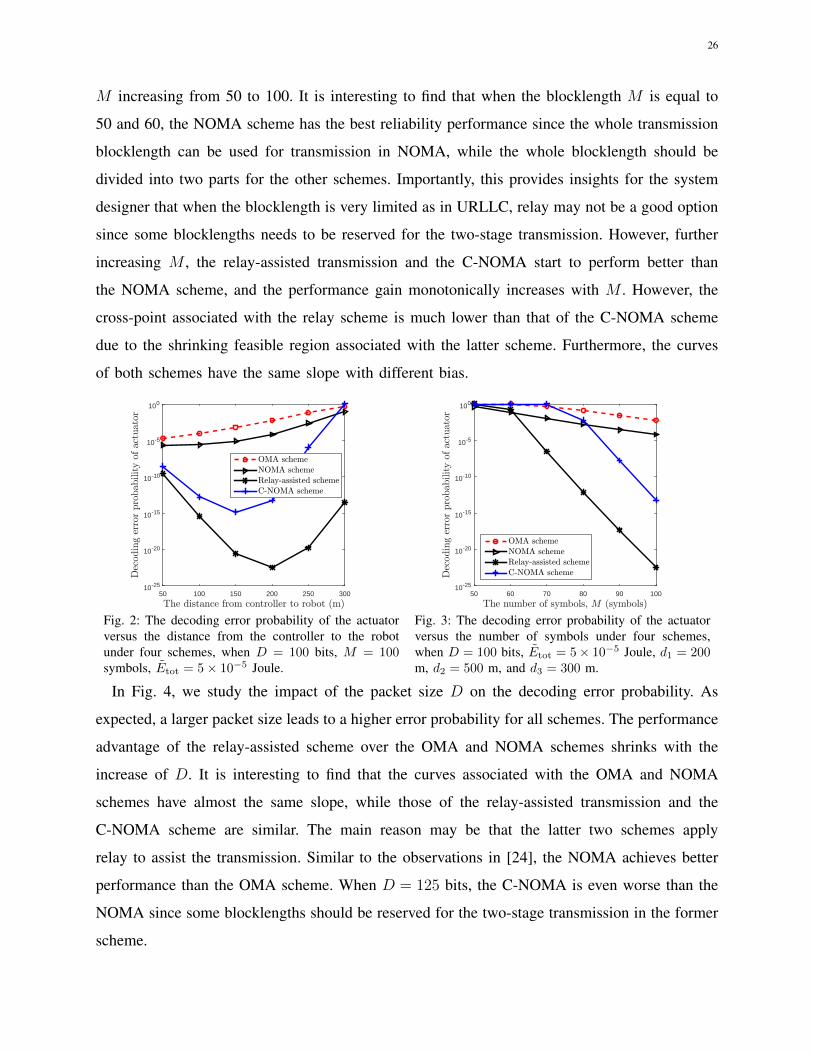
In Fig. 2, we first study the impact of distance d1 on the decoding error probability. We
observe that relay-assisted transmission outperforms the other three schemes. It is interesting to
see that when the robot moves from the controller to the actuator, the decoding error probability
achieved by the OMA and NOMA schemes always decreases. The main reason is that the
channel gain from controller to robot decreases with increasing the distance, so the energy and
blocklength required for the robot to guarantee its error probability requirement increases. As a
result, the available energy and blocklength for the actuator will decrease. On the other hand,
the reliability performances achieved by the C-NOMA and relay-assisted schemes first increase
and then decrease when the robot moves in the line. This can be explained as follows. When the
robot moves from 50 m to 150 m for the C-NOMA and 200 m for relay-assisted scheme, the
channel gain from the robot to the actuator becomes weak, which is the performance bottleneck
that limits the decoding error probability of the actuator. However, when the robot continues
to move towards the actuator, the transmission link from the controller to the robot becomes
the bottleneck link. Hence, the distance d1 can be optimized to additionally improve the system
performance, which can be treated in the future work. It is interesting to observe that the C-
NOMA performs worse than the relay-assisted scheme, which is due to the larger feasible region
for the latter scheme as explained at the end of Section III.
In Fig. 3, we examine the impact of available blocklength M on the decoding error probability
of the actuator. As expected, larger M leads to much better reliability performance in all schemes,
and the decoding error probability achieved by the relay scheme decreases from 1 to 10−22 with
26
M increasing from 50 to 100. It is interesting to find that when the blocklength M is equal to
50 and 60, the NOMA scheme has the best reliability performance since the whole transmission
blocklength can be used for transmission in NOMA, while the whole blocklength should be
divided into two parts for the other schemes. Importantly, this provides insights for the system
designer that when the blocklength is very limited as in URLLC, relay may not be a good option
since some blocklengths needs to be reserved for the two-stage transmission. However, further
increasing M , the relay-assisted transmission and the C-NOMA start to perform better than
the NOMA scheme, and the performance gain monotonically increases with M . However, the
cross-point associated with the relay scheme is much lower than that of the C-NOMA scheme
due to the shrinking feasible region associated with the latter scheme. Furthermore, the curves
of both schemes have the same slope with different bias.
The distance from controller to robot (m)50 100 150 200 250 300
Dec
odin
ger
rorpro
bab
ility
ofac
tuat
or
10-25
10-20
10-15
10-10
10-5
100
OMA schemeNOMA schemeRelay-assisted schemeC-NOMA scheme
Fig. 2: The decoding error probability of the actuatorversus the distance from the controller to the robotunder four schemes, when D = 100 bits, M = 100symbols, Etot = 5× 10⁻⁵ Joule.
The number of symbols, M (symbols)50 60 70 80 90 100
Dec
odin
ger
rorpro
bab
ility
ofac
tuat
or
10-25
10-20
10-15
10-10
10-5
100
OMA schemeNOMA schemeRelay-assisted schemeC-NOMA scheme
Fig. 3: The decoding error probability of the actuatorversus the number of symbols under four schemes,when D = 100 bits, Etot = 5× 10⁻⁵ Joule, d1 = 200m, d2 = 500 m, and d3 = 300 m.
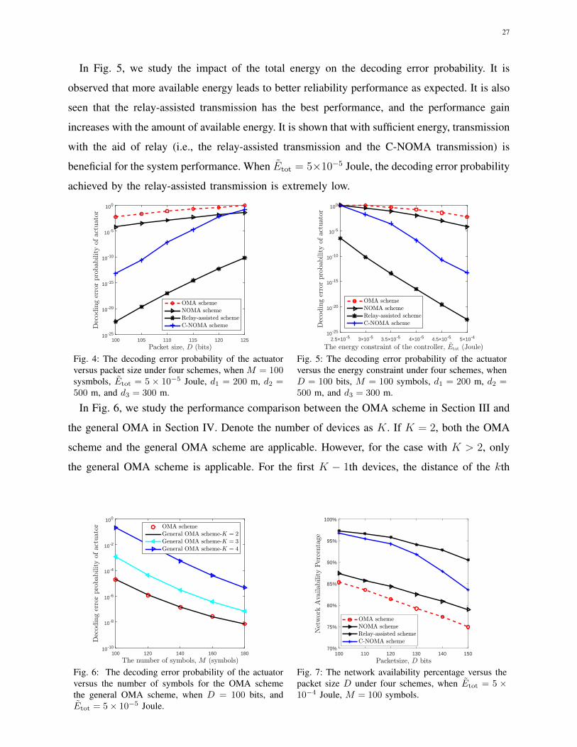
In Fig. 4, we study the impact of the packet size D on the decoding error probability. As
expected, a larger packet size leads to a higher error probability for all schemes. The performance
advantage of the relay-assisted scheme over the OMA and NOMA schemes shrinks with the
increase of D. It is interesting to find that the curves associated with the OMA and NOMA
schemes have almost the same slope, while those of the relay-assisted transmission and the
C-NOMA scheme are similar. The main reason may be that the latter two schemes apply
relay to assist the transmission. Similar to the observations in [24], the NOMA achieves better
performance than the OMA scheme. When D = 125 bits, the C-NOMA is even worse than the
NOMA since some blocklengths should be reserved for the two-stage transmission in the former
scheme.
27
In Fig. 5, we study the impact of the total energy on the decoding error probability. It is
observed that more available energy leads to better reliability performance as expected. It is also
seen that the relay-assisted transmission has the best performance, and the performance gain
increases with the amount of available energy. It is shown that with sufficient energy, transmission
with the aid of relay (i.e., the relay-assisted transmission and the C-NOMA transmission) is
beneficial for the system performance. When Etot = 5×10⁻⁵ Joule, the decoding error probability
achieved by the relay-assisted transmission is extremely low.
Packet size, D (bits)100 105 110 115 120 125
Dec
odin
ger
ror
pro
bab
ility
ofac
tuat
or
10-25
10-20
10-15
10-10
10-5
100
OMA schemeNOMA schemeRelay-assisted schemeC-NOMA scheme
Fig. 4: The decoding error probability of the actuatorversus packet size under four schemes, when M = 100sysmbols, Etot = 5 × 10⁻⁵ Joule, d1 = 200 m, d2 =500 m, and d3 = 300 m.
The energy constraint of the controller, ~Etot (Joule)2.5×10⁻⁵ 3×10⁻⁵ 3.5×10⁻⁵ 4×10⁻⁵ 4.5×10⁻⁵ 5×10⁻⁴
Dec
odin
ger
ror
pro
bab
ility
ofac
tuat
or
10-25
10-20
10-15
10-10
10-5
100
OMA schemeNOMA schemeRelay-assisted schemeC-NOMA scheme
Fig. 5: The decoding error probability of the actuatorversus the energy constraint under four schemes, whenD = 100 bits, M = 100 symbols, d1 = 200 m, d2 =500 m, and d3 = 300 m.
In Fig. 6, we study the performance comparison between the OMA scheme in Section III and
the general OMA in Section IV. Denote the number of devices as K. If K = 2, both the OMA
scheme and the general OMA scheme are applicable. However, for the case with K > 2, only
the general OMA scheme is applicable. For the first K − 1th devices, the distance of the kth
The number of symbols, M (symbols)100 120 140 160 180
Decodingerrorprobab
ilityof
actuator
10-10
10-8
10-6
10-4
10-2
100
OMA schemeGeneral OMA scheme-K = 2General OMA scheme-K = 3General OMA scheme-K = 4
Fig. 6: The decoding error probability of the actuatorversus the number of symbols for the OMA schemethe general OMA scheme, when D = 100 bits, andEtot = 5× 10⁻⁵ Joule.
100 110 120 130 140 150 70%
75%
80%
85%
90%
95%
100%
Fig. 7: The network availability percentage versus thepacket size D under four schemes, when Etot = 5 ×10⁻⁴ Joule, M = 100 symbols.
28
device to the controller is set as 50× k m, while the distance of the last device to the controller
is set as 500 m. The other parameters are the same as the previous figures. It is interesting to
find that the decoding error probability achieved by the OMA scheme and the general OMA
scheme is almost the same when K = 2, which implies that the general OMA can achieve
almost the globally optimal solution in this setup. However, the general OMA scheme has lower
complexity than the OMA scheme. It is also noted from this figure that the decoding error
probability achieved by the Kth device increases when the number of total devices increases.
This can be explained as follows. When the number of total devices increases, the total resource
such as energy and channel blocklength allocated to the first K − 1 devices will increase. Then,
the left resource allocated for the Kth device decreases, leading to its sworse decoding error
probability performance.
B. Network Availability Performance (Channel Generation Times=1000)
In this subsection, the small-scale fading channel is taken into consideration in the channel
gain, and we study the network availability performance, which is defined as the ratio of the
number of channel generations, where the decoding error probability achieved by both devices is
no larger than 10−9, to the total number of channel generations [2]. In the following simulations,
the total number of channel generations is set as 1000. The distances are set as d1 = 200 m,
d2 = 500 m, and d3 = 300 m, respectively.
Fig. 7 illustrates the network availability performance versus the packet size D for all schemes.
As expected, the network availability performance achieved by all schemes decreases with D. The
relay-assisted transmission has the best network availability performance over the whole region of
D. It is observed that when D = 100 bits, the network availability percentage of the relay-assisted
scheme and the C-NOMA scheme is almost the same, as high as 98%. However, the performance
gap of these two schemes increases rapidly with D due to the shrinking feasible region of the
C-NOMA scheme compared to the relay-assisted transmission. However, the network availability
performance for both the OMA scheme and the NOMA scheme are lower than that of relay-
assisted scheme and C-NOMA scheme, and the network availability percentage is as low as 87%
for NOMA scheme even when D = 100 bits.
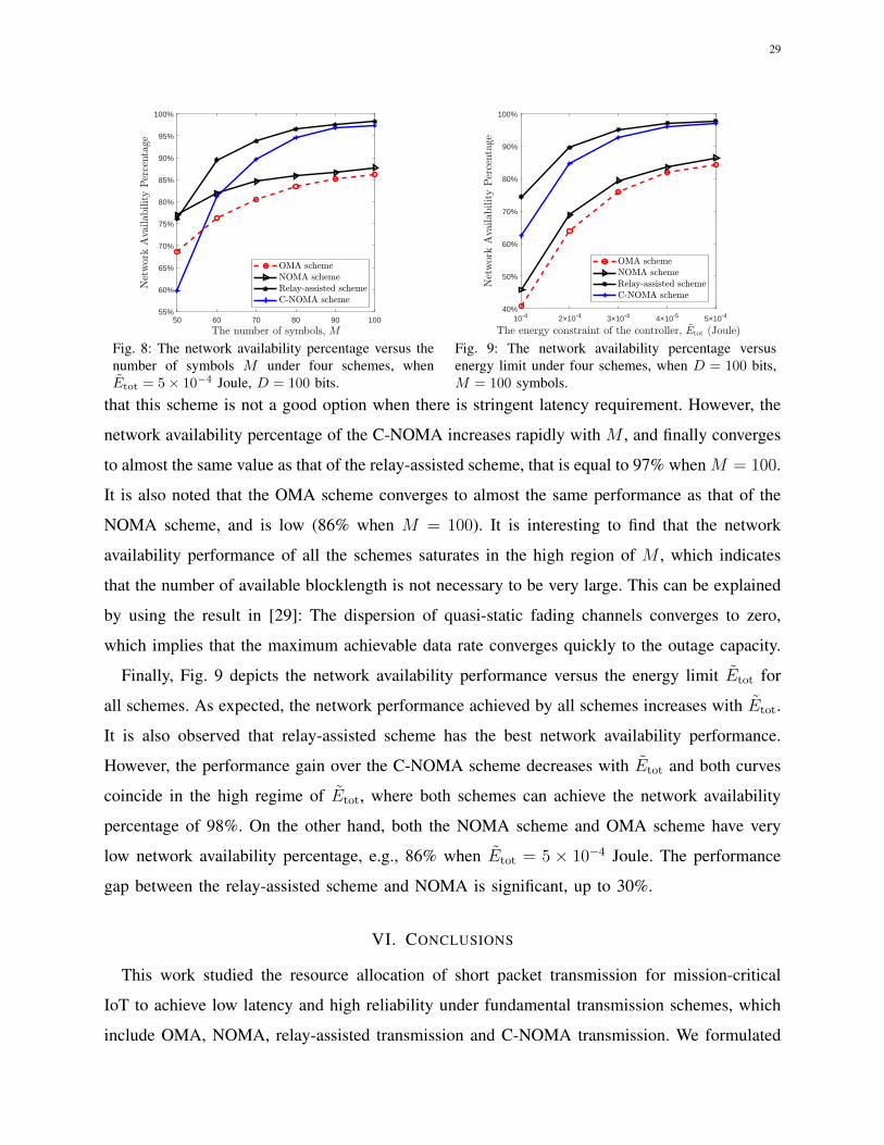
Fig. 8 shows the network availability performance versus the number of symbols for four
schemes. As expected, the network availability performance increases with M for all schemes.
The NOMA scheme performs slightly better than the relay scheme when M = 50. It is interesting
to note that the C-NOMA scheme has the worst performance when M = 50, which means
29
50 60 70 80 90 100 55%
60%
65%
70%
75%
80%
85%
90%
95%
100%
Fig. 8: The network availability percentage versus thenumber of symbols M under four schemes, whenEtot = 5× 10⁻⁴ Joule, D = 100 bits.
10-4 2×10⁻⁴ 3×10⁻⁴ 4×10⁻⁵ 5×10⁻⁴ 40%
50%
60%
70%
80%
90%
100%
Fig. 9: The network availability percentage versusenergy limit under four schemes, when D = 100 bits,M = 100 symbols.
that this scheme is not a good option when there is stringent latency requirement. However, the
network availability percentage of the C-NOMA increases rapidly with M , and finally converges
to almost the same value as that of the relay-assisted scheme, that is equal to 97% when M = 100.
It is also noted that the OMA scheme converges to almost the same performance as that of the
NOMA scheme, and is low (86% when M = 100). It is interesting to find that the network
availability performance of all the schemes saturates in the high region of M , which indicates
that the number of available blocklength is not necessary to be very large. This can be explained
by using the result in [29]: The dispersion of quasi-static fading channels converges to zero,
which implies that the maximum achievable data rate converges quickly to the outage capacity.
Finally, Fig. 9 depicts the network availability performance versus the energy limit Etot for
all schemes. As expected, the network performance achieved by all schemes increases with Etot.
It is also observed that relay-assisted scheme has the best network availability performance.
However, the performance gain over the C-NOMA scheme decreases with Etot and both curves
coincide in the high regime of Etot, where both schemes can achieve the network availability
percentage of 98%. On the other hand, both the NOMA scheme and OMA scheme have very
low network availability percentage, e.g., 86% when Etot = 5 × 10⁻⁴ Joule. The performance
gap between the relay-assisted scheme and NOMA is significant, up to 30%.
VI. CONCLUSIONS
This work studied the resource allocation of short packet transmission for mission-critical
IoT to achieve low latency and high reliability under fundamental transmission schemes, which
include OMA, NOMA, relay-assisted transmission and C-NOMA transmission. We formulated

30
an optimization problem to minimize the decoding error probability for the actuator with lower
channel gain while guaranteeing that the robot achieved a low error probability target. To facilitate
the optimal design of the blocklength and power allocation, we derived the tight bounds on the
blocklength and the transmit power for all schemes. Simulation results demonstrated that relay-
assisted transmission significantly outperforms the other schemes for most cases in terms of
packet error probability as well as network availability percentage performance. It was also
noted that the NOMA scheme performs well when the delay requirement is very stringent.
For the C-NOMA and relay-assisted schemes, there exists one optimal transmission distance
between the central controller and the robot. We also observed that the general OMA scheme
can achieve almost the same performance as the OMA scheme, while the former scheme has a
lower complexity.
Concerning our future work, we will consider a more general scenario with more than two
devices for the other three schemes.
APPENDIX A
PROOF OF LEMMA 1
We prove it by using contradiction. In the following, we first prove that constraint (7b) holds
with equality at the optimum solution. The second one can be proved similarly.
Denote the optimal solution of Problem (7) as s? = {m?1,m
?2, p
?1, p
?2} and the corresponding
ε1 and ε2 are denoted as ε?1 and ε?2, respectively. Suppose that ε?1 is strictly smaller than εmax1 ,
i.e., ε?1 < εmax1 . In Proposition 1 of [24], the author proved that Q (f (γ1,m1, D)) monotonically
decreases with γ1. Then, we can construct a new solution s# = {m?1,m
?2, p
#1 , p
#2 }, where p#
1 =
p?1−∆p and p#2 = p?2 +
m?1∆p
m?2
with ∆p > 0. It can be verified that the following equation holds,
m?1p
#1 +m?
2p#2 = m?
1p?1 +m?
2p?2 ≤ Etot. (73)
Hence, the new constructed solution s# still satisfies the energy constraint (7c). In addition,
we can always find a proper positive ∆p such that the new ε#1 with the new solution s# is equal
to εmax1 , i.e., ε#
1 = εmax1 , which satisfies constraint (7b). Hence, the new constructed solution s#
is a feasible solution of Problem (7). Since p#2 > p?2, we have ε#
2 < ε?2. This contradicts with
the assumption that s? is an optimal solution. The same method is applicable to the proof of the
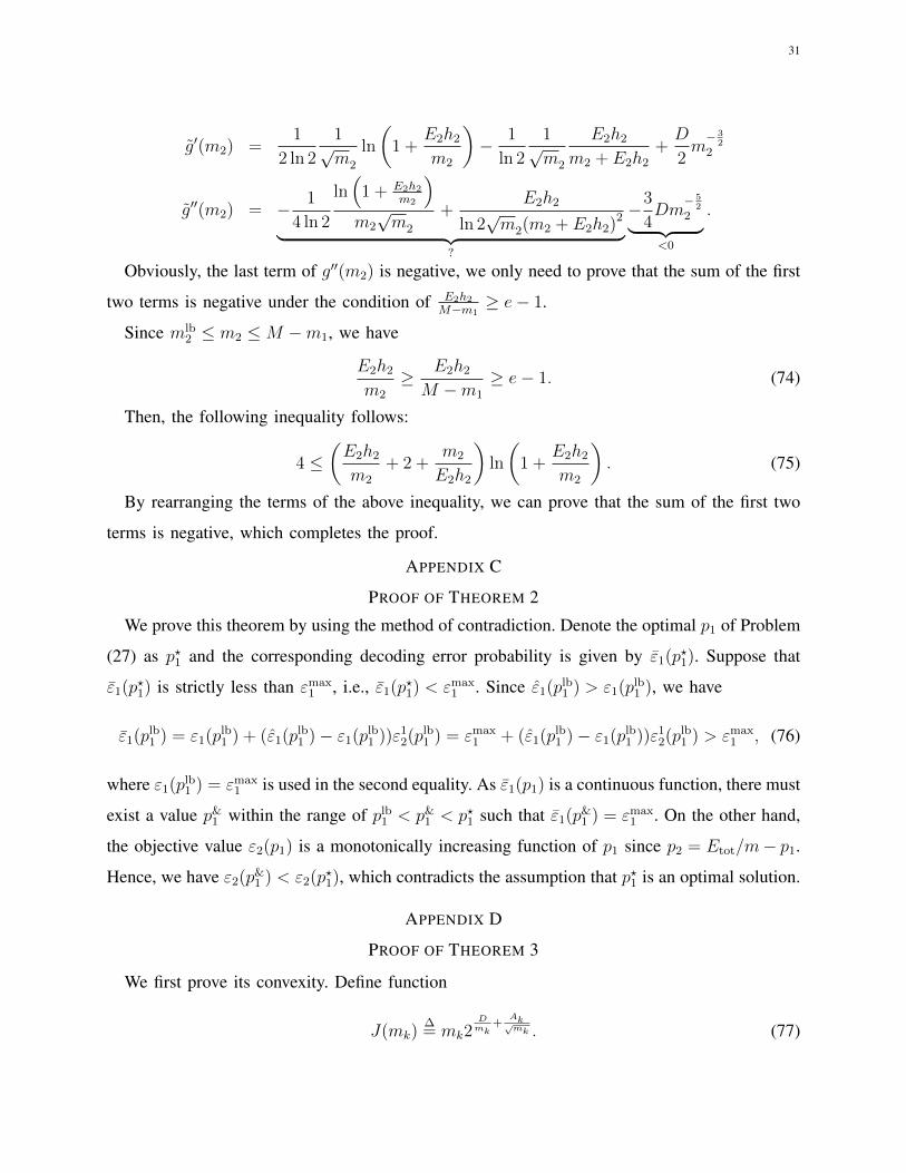
second conclusion.APPENDIX B
PROOF OF THEOREM 1
The first and second derivative of function g(m2) w.r.t. m2 can be calculated as
31
g′(m2) =1
2 ln 2
1√m2
ln
(1 +
E2h2
m2
)− 1
ln 2
1√m2
E2h2
m2 + E2h2
+D
2m− 3
22
g′′(m2) = − 1
4 ln 2
ln(
1 + E2h2m2
)m2
√m2
+E2h2
ln 2√m2(m2 + E2h2)2︸ ︷︷ ︸
?
−3
4Dm
− 52
2︸ ︷︷ ︸<0
.
Obviously, the last term of g′′(m2) is negative, we only need to prove that the sum of the first
two terms is negative under the condition of E2h2M−m1
≥ e− 1.
Since mlb2 ≤ m2 ≤M −m1, we have
E2h2
m2
≥ E2h2
M −m1
≥ e− 1. (74)
Then, the following inequality follows:
4 ≤(E2h2
m2
+ 2 +m2
E2h2
)ln
(1 +
E2h2
m2
). (75)
By rearranging the terms of the above inequality, we can prove that the sum of the first two
terms is negative, which completes the proof.
APPENDIX C
PROOF OF THEOREM 2
We prove this theorem by using the method of contradiction. Denote the optimal p1 of Problem
(27) as p?1 and the corresponding decoding error probability is given by ε1(p?1). Suppose that
ε1(p?1) is strictly less than εmax1 , i.e., ε1(p?1) < εmax
1 . Since ε1(plb1 ) > ε1(plb
1 ), we have
ε1(plb1 ) = ε1(plb
1 ) + (ε1(plb1 )− ε1(plb
1 ))ε12(plb
1 ) = εmax1 + (ε1(plb
1 )− ε1(plb1 ))ε1
2(plb1 ) > εmax
1 , (76)
where ε1(plb1 ) = εmax
1 is used in the second equality. As ε1(p1) is a continuous function, there must
exist a value p&1 within the range of plb
1 < p&1 < p?1 such that ε1(p&
1 ) = εmax1 . On the other hand,
the objective value ε2(p1) is a monotonically increasing function of p1 since p2 = Etot/m− p1.
Hence, we have ε2(p&1 ) < ε2(p?1), which contradicts the assumption that p?1 is an optimal solution.
APPENDIX D
PROOF OF THEOREM 3
We first prove its convexity. Define function
J(mk)∆= mk2
Dmk
+Ak√mk . (77)
32
Then, g (mk) can be rewritten as g (mk) = (J(mk)−mk)/hk. Then, if J(mk) is convex, function
g (mk) is also convex. Hence, in the following, we prove that J(mk) is a convex function. Define
function J(mk) as
J(mk)∆= ln (J(mk)) = ln(mk) +
(D
mk
+Ak√mk
)ln 2. (78)
The second-order derivative of J(mk) w.r.t. mk is given by
J ′′(mk) =1
m3k
(2D ln 2−mk +
3
4Ak√mk ln 2
). (79)
Note that the denominator of (79) is a quadratic function of√mk. Hence, if the inequality in
(60) is satisfied, J ′′(mk) is always positive, which means J(mk) is a convex function of mk.
Since J(mk) = eJ(mk), according to the composition rule in [31], we can show that J(mk) is
also a convex function. Hence, g (mk) is a convex function of mk when the inequality in (60)
is satisfied.
Now, we proceed to prove that g (mk) is a monotonically decreasing function of mk. The
first-order derivative of g (mk) w.r.t. mk is given by
g′ (mk) =1
hk
[2
Dmk
+Ak√mk
(− D
mk
ln 2− ln 2
2
Ak√mk
+ 1
)− 1
]. (80)
Since g (mk) is a convex function, we have g′′ (mk) ≥ 0, which means g′ (mk) is a monotonically
increasing function. Hence, we have
g′ (mk) < g′ (∞) = 0. (81)
Hence, g (mk) is a monotonically decreasing function of mk when the inequality in (60) holds.
REFERENCES
[1] M. Shafi, A. F. Molisch, P. J. Smith, T. Haustein, P. Zhu, P. De Silva, F. Tufvesson, A. Benjebbour, and G. Wunder, “5G:
A Tutorial Overview of Standards, Trials, Challenges, Deployment, and Practice,” IEEE J. Sel. Areas Commun., vol. 35,
no. 6, pp. 1201–1221, June 2017.
[2] P. Schulz, M. Matthe, H. Klessig, M. Simsek, G. Fettweis, J. Ansari, S. A. Ashraf, B. Almeroth, J. Voigt, and I. Riedel,
“Latency Critical IoT Applications in 5G: Perspective on the Design of Radio Interface and Network Architecture,” IEEE
Commun. Mag., vol. 55, no. 2, pp. 70–78, February 2017.
[3] M. Bennis, M. Debbah, and H. V. Poor, “Ultrareliable and low-latency wireless communication: Tail, risk, and scale,”
Proceedings of the IEEE, vol. 106, no. 10, pp. 1834–1853, 2018.

33
[4] P. Popovski, J. J. Nielsen, C. Stefanovic, E. de Carvalho, E. G. Strom, K. F. Trillingsgaard, A. Bana, D. Kim,
R. Kotaba, and J. Park, “Ultra-reliable low-latency communication (URLLC): principles and building blocks,” arXiv preprint
arXiv:1708.07862, 2017.
[5] C. She, C. Yang, and T. Q. S. Quek, “Radio Resource Management for Ultra-Reliable and Low-Latency Communications,”
IEEE Commun. Mag., vol. 55, no. 6, pp. 72–78, 2017.
[6] J. J. Nielsen, R. Liu, and P. Popovski, “Ultra-Reliable Low Latency Communication Using Interface Diversity,” IEEE
Trans. Commun., vol. 66, no. 3, pp. 1322–1334, March 2018.
[7] M. Mozaffari, W. Saad, M. Bennis, Y.-H. Nam, and M. Debbah, “A tutorial on UAVs for wireless networks: Applications,
challenges, and open problems,” IEEE Commun. Surveys & Tutorials, 2019.
[8] M. Simsek, A. Aijaz, M. Dohler, J. Sachs, and G. Fettweis, “5G-enabled tactile internet,” IEEE J. Sel. Areas Commun.,
vol. 34, no. 3, pp. 460–473, 2016.
[9] H. Ren, N. Liu, C. Pan, M. Elkashlan, A. Nallanathan, X. You, and L. Hanzo, “Power-and rate-adaptation improves the
effective capacity of C-RAN for Nakagami-m fading channels,” IEEE Trans. Veh. Technol., vol. 67, no. 11, pp. 10 841–
10 855, 2018.
[10] ——, “Low-latency C-RAN: An next-generation wireless approach,” IEEE Veh. Technol. Mag., vol. 13, no. 2, pp. 48–56,
2018.
[11] A. Varghese and D. Tandur, “Wireless requirements and challenges in Industry 4.0,” in 2014 IC3I, Nov 2014, pp. 634–638.
[12] L. Liu and W. Yu, “A D2D-Based Protocol for Ultra-Reliable Wireless Communications for Industrial Automation,” IEEE
Trans. Wireless Commun., vol. 17, no. 8, pp. 5045–5058, Aug 2018.
[13] O. N. Yilmaz, Y.-P. E. Wang, N. A. Johansson, N. Brahmi, S. A. Ashraf, and J. Sachs, “Analysis of ultra-reliable and
low-latency 5G communication for a factory automation use case,” in 2015 IEEE ICC). IEEE, 2015, pp. 1190–1195.
[14] G. Durisi, T. Koch, and P. Popovski, “Toward Massive, Ultrareliable, and Low-Latency Wireless Communication With
Short Packets,” Proc. IEEE, vol. 104, no. 9, pp. 1711–1726, Sept 2016.
[15] Y. Polyanskiy, H. V. Poor, and S. Verdu, “Channel Coding Rate in the Finite Blocklength Regime,” IEEE Trans. Inf.
Theory, vol. 56, no. 5, pp. 2307–2359, May 2010.
[16] K. F. Trillingsgaard and P. Popovski, “Downlink Transmission of Short Packets: Framing and Control Information
Revisited,” IEEE Trans. Commun., vol. 65, no. 5, pp. 2048–2061, May 2017.
[17] C. She, Z. Chen, C. Yang, T. Q. Quek, Y. Li, and B. Vucetic, “Improving network availability of ultra-reliable and
low-latency communications with multi-connectivity,” IEEE Trans. Commun., vol. 66, no. 11, pp. 5482–5496, 2018.
[18] J. Ostman, G. Durisi, E. G. Strom, M. C. Coskun, and G. Liva, “Short packets over block-memoryless fading channels:
Pilot-assisted or noncoherent transmission?” IEEE Trans. Commun., vol. 67, no. 2, pp. 1521–1536, 2019.
[19] Y. Hu, J. Gross, and A. Schmeink, “On the Capacity of Relaying With Finite Blocklength,” IEEE Trans. Veh. Technol.,
vol. 65, no. 3, pp. 1790–1794, March 2016.
[20] Y. Hu, A. Schmeink, and J. Gross, “Blocklength-Limited Performance of Relaying Under Quasi-Static Rayleigh Channels,”
IEEE Trans. Wireless Commun., vol. 15, no. 7, pp. 4548–4558, July 2016.
[21] Y. Gu, H. Chen, Y. Li, L. Song, and B. Vucetic, “Short-Packet Two-Way Amplify-and-Forward Relaying,” IEEE Sig. Proc.
Lett., vol. 25, no. 2, pp. 263–267, Feb 2018.
[22] O. L. A. Lopez, R. D. Souza, H. Alves, and E. M. G. Fernandez, “Ultra reliable short message relaying with wireless
power transfer,” in 2017 ICC, May 2017, pp. 1–6.
[23] Y. Hu, M. C. Gursoy, and A. Schmeink, “Efficient transmission schemes for low-latency networks: NOMA vs. relaying,”
in 2017 IEEE PIMRC, Oct 2017, pp. 1–6.

34
[24] X. Sun, S. Yan, N. Yang, Z. Ding, C. Shen, and Z. Zhong, “Short-Packet Downlink Transmission With Non-Orthogonal
Multiple Access,” IEEE Trans. Wireless Commun., vol. 17, no. 7, pp. 4550–4564, July 2018.
[25] C. She, C. Yang, and T. Q. S. Quek, “Joint Uplink and Downlink Resource Configuration for Ultra-Reliable and Low-
Latency Communications,” IEEE Trans. Commun., vol. 66, no. 5, pp. 2266–2280, May 2018.
[26] Y. Hu, Y. Zhu, M. C. Gursoy, and A. Schmeink, “SWIPT-enabled relaying in IoT networks operating with finite blocklength
codes,” IEEE J. Sel. Areas Commun., vol. 37, no. 1, pp. 74–88, 2019.
[27] C. Pan, H. Ren, Y. Deng, M. Elkashlan, and A. Nallanathan, “Joint blocklength and location optimization for URLLC-
enabled UAV relay systems,” IEEE Commun. Lett., vol. 23, no. 3, pp. 498–501, March 2019.
[28] C. Shannon, “A Mathematical Theory of Communication,” The Bell System Technical Journal, vol. 27, no. 1, pp. 379–423,
July 1948.
[29] W. Yang, G. Durisi, T. Koch, and Y. Polyanskiy, “Quasi-static multiple-antenna fading channels at finite blocklength,”
IEEE Trans. Inf. Theory, vol. 60, no. 7, pp. 4232–4265, July 2014.
[30] Y. Liu, Z. Ding, M. Elkashlan, and H. V. Poor, “Cooperative Non-orthogonal Multiple Access With Simultaneous Wireless
Information and Power Transfer,” IEEE J. Sel. Areas Commun., vol. 34, no. 4, pp. 938–953, April 2016.
[31] S. Boyd and L. Vandenberghe, “Convex optimization,” Cambridge, U.K.: Cambridge Univ. Press, 2004.
[32] C. Pan, H. Ren, K. Wang, M. Elkashlan, A. Nallanathan, J. Wang, and L. Hanzo, “Intelligent reflecting surface enhanced
MIMO broadcasting for simultaneous wireless information and power transfer,” arXiv preprint arXiv:1908.04863, 2019.
[33] E. U. T. R. Access, “Further advancements for E-UTRA physical layer aspects,” 3GPP TR 36.814, Tech. Rep., 2010.