Embed Size (px)
Citation preview

JOINT IMPLEMENTATION PROJECT DESIGN DOCUMENT FORM - Version 01
Joint Implementation Supervisory Committee page 1
This template shall not be altered. It shall be completed without modifying/adding headings or logo, format or font.
JOINT IMPLEMENTATION PROJECT DESIGN DOCUMENT FORM
Version 01 - in effect as of: 15 June 2006
CONTENTS
A. General description of the project
B. Baseline
C. Duration of the project / crediting period
D. Monitoring plan
E. Estimation of greenhouse gas emission reductions
F. Environmental impacts
G. Stakeholders’ comments
Annexes
Annex 1: Contact information on project participants
Annex 2: Baseline information
Annex 3: Monitoring plan

JOINT IMPLEMENTATION PROJECT DESIGN DOCUMENT FORM - Version 01
Joint Implementation Supervisory Committee page 2
This template shall not be altered. It shall be completed without modifying/adding headings or logo, format or font.
SECTION A. General description of the project
A.1. Title of the project:
>>
RWE Renewables Polska Wind Power Project
PDD Version: 01
Date: 24 February 2012
A.2. Description of the project:
>>
The RWE Renewables Polska Wind Power Project (hereafter referred to as the project) is located in
Northern Poland.
The objective of the project is to generate electricity using renewable wind resources and to supply the
generated electricity to the Polish Grid. The project will involve construction of the wind turbines and
also the accompanying infrastructure e.g. internal access roads and power lines for transferring the
generated electricity to the grid.
The project consists of three sites which belong to RWE Renewables Polska with Special Purpose
Vehicles (SPV) for each wind farm. The names of the SPVs are as follows:
- Park Wiatrowy Suwalki Sp. z o.o.
- Piecki Sp. z o.o. (51 % of the shares are owned by RWE Renewables Polska, 49% of the shares
are owned by HSE)
- Park Wiatrowy Tychowo Sp. z o.o.
The project specific details can be found below:
Site No Location No of
Turbines
Capacity of
Turbine (MW)
Total Installed
Capacity (MW)
1 Suwalki 18 2,3 41,4
2 Piecki 15 2,3 34,5
3 Tychowo 16 2 32
Total 49 107,9
For sites 1 and 3 the wind turbines are produced by Siemens Wind Power GmbH and site 2 uses wind
turbines produced by Gamesa Wind Poland Sp. z o.o.
The project will contribute to greenhouse gas (GHG) emission reductions by supplying renewable
electrictiy to the grid and by replacing this part of electricity generation from a fossil fuel-fired power
intensive grid. The estimated annual GHG emission reduction is approximately 196,388 tCO2e.
The project will not only supply renewable electricity to the grid but will also contribute to sustainable
energy development in Poland by:
� Reducing the emission of GHG resulting from the power generation industry, compared with the
business-as-usual-scenarios;
� Promote the development of renewable energy in Poland;
� Creating new employment opportunities; � Mitigate the dependence of fossil fuel power supply and accelerate local economic development.

JOINT IMPLEMENTATION PROJECT DESIGN DOCUMENT FORM - Version 01
Joint Implementation Supervisory Committee page 3
This template shall not be altered. It shall be completed without modifying/adding headings or logo, format or font.
A.3. Project participants:
>>
Name of the Party
involved
Private and/or public entity(ies)
Project participants
Kindly indicate if the Party
involved wishes to be considered as
project participants
Poland (Host Party) RWE Renewables Polska Sp. z o.o. No
Germany RWE Power AG No
RWE Renewables Polska is owned by RWE Innogy which pools the renewable energy expertise and
power plants of the RWE Group. RWE Renewables Polska is planning to construct a total of 300 MW
generation by wind power stations by 2015. In 2009 it has built the first wind turbines in Poland which
has been the Suwalki wind park.
RWE Power AG is the electricity producer within the RWE Group. Its portfolio is based on lignite, hard
coal, nuclear energy and gas. With an installed capacity of 34,028 MW (2010) and an electricity
production of 165.1 bn kWh (2010), RWE is one of the biggest electricity generators in Europe.
Curently, RWE Power participates in more than 100 CDM and JI projects worldwide.
A.4. Technical description of the project:
A.4.1. Location of the project:
>>
A.4.1.1. Host Party(ies):
>>
Poland (Republic of Poland)
A.4.1.2. Region/State/Province etc.:
>>
Project Site Voivodship / County
1 Podlaskie / Suwałki
2 Podlaskie / Suwałki
3 West Pomeranian / Stargard Szczeciński
A.4.1.3. City/Town/Community etc.:
>>
Project Site Municipality / Community
1 Suwałki / Biała Woda
2 Filipów / Piecki
3 Stargard Szczeciński / Trzebiatów
A.4.1.4. Detail of physical location, including information allowing the unique
identification of the project (maximum one page):
>>
The project consist of three site which are located in Norther Poland at:
- Site 1 - Park Wiatrowy Suwalki, Biala Woda 25, 16-402 Suwalki, Poland
- Site 2 - Park Wiatrowy Piecki, Stacja GPZ Park Wiatrowy, 16-402 Piecki, Poland
- Site 3 - Park Wiatrowy Tychowo, Trzebiatów 13, 73-131 Pęzino, Poland
JOINT IMPLEMENTATION PROJECT DESIGN DOCUME
Joint Implementation Supervisory Committee
This template shall not be altered. It shall be completed without modifying/adding headings or logo, format or font.
The geographical coordinates of the
� Suwalki: 22° 52’39” E and 54°09’30” N
� Piecki: 22° 46’04” E and 54°11’01” N
� Tychowo: 15° 09’22” E and 53°19’11” N
Figure A
A.4.2. Technology(ies) to be employed, or measures, operations or actions to be
implemented by the project:
>>
The proposed project will use 18 wind
The main technical parameters are presented in Tab
Table A-4-1 Main technical parameter
Part
Turbine
Rated Power
Rotor diameter
Height of hub
Start up speed
Shutdown speed
JOINT IMPLEMENTATION PROJECT DESIGN DOCUMENT FORM - Version 01
Joint Implementation Supervisory Committee
This template shall not be altered. It shall be completed without modifying/adding headings or logo, format or font.
The geographical coordinates of the sites are:
E and 54°09’30” N
E and 54°11’01” N
E and 53°19’11” N
Figure A-4-1 Geographical position of the project sites
Technology(ies) to be employed, or measures, operations or actions to be
wind turbine generators manufactured by Siemens at the Suwalki site
The main technical parameters are presented in Table A-4-1:
1 Main technical parameters of Suwalki wind park
Parameter
Siemens SWT
2.3 MW
93 m
103 m
4 m/s
25 m/s
Version 01
page 4
This template shall not be altered. It shall be completed without modifying/adding headings or logo, format or font.
Technology(ies) to be employed, or measures, operations or actions to be
Siemens at the Suwalki site.
s of Suwalki wind park
Parameter
Siemens SWT-2.3
2.3 MW

JOINT IMPLEMENTATION PROJECT DESIGN DOCUMENT FORM - Version 01
Joint Implementation Supervisory Committee page 5
This template shall not be altered. It shall be completed without modifying/adding headings or logo, format or font.
The proposed project will use 16 wind turbine generators manufactured by Gamesa at the Piecki site. The
main technical parameters are presented in Table A-4-3:
Table A-4-2 Main technical parameters of Piecki wind park
Part Parameter
Turbine Gamesa G90
Rated Power 2 MW
Rotor diameter 90 m
Hun height 78 m
Start up speed 3 m/s
Shutdown speed 25 m/s
The proposed project will use 15 wind turbine generators manufactured by Siemens at the Tychowo site.
The main technical parameters are presented in Table A-4-2:
Table A-4-3 Main technical parameters of Tychowo wind park
Part Parameter
Turbine Siemens SWT-2.3
Rated Power 2.3 MW
Rotor diameter 93 m
Hun height 103 m
Start up speed 4 m/s
Shutdown speed 25 m/s
Implementation Schedule
The decision to undertake the projects PW Tychowo and PW Suwałki has been made by the Board of
RWE AG in 03.04.2007. and the decision to undertake the projetct PW Piecki has been made by the
Board of RWE Innogy in 01.12.2009.
For site 1, in March 2008 the investment stage has been started by signing the Turbine Supply
Agreement with Siemens Wind Power GmbH. Construction works began in June 2008 and lasted until
August 2009. The official commissioing of the Suwalki wind park has been in October 2009.
For site 2, the investment stage has been started in November 2010 by signing an umbrella agreement
with Gamesa Wind Poland Sp. z o.o. The construction works began in February 2009 and lasted until
September 2010. The official commissioning of the Piecki wind park has been in November 2010.
For site 3, the investment stage has been started in April 2008 by signing the turbine supply agreement
with Siemens Wind Power GmbH. Construction works began in February 2010 and lasted one year. The
official commissioning of the Tychowo wind park has been in February 2011.
The expected lifetime of the project is 20 years. For all sites, there are O&M agreements with the specific
equipment manufacturers (Siemens, Gamesa) for five years.
JOINT IMPLEMENTATION PROJECT DESIGN DOCUMENT FORM - Version 01
Joint Implementation Supervisory Committee page 6
This template shall not be altered. It shall be completed without modifying/adding headings or logo, format or font.
A.4.3. Brief explanation of how the anthropogenic emissions of greenhouse gases by
sources are to be reduced by the proposed JI project, including why the emission reductions would
not occur in the absence of the proposed project, taking into account national and/or sectoral
policies and circumstances:
> >
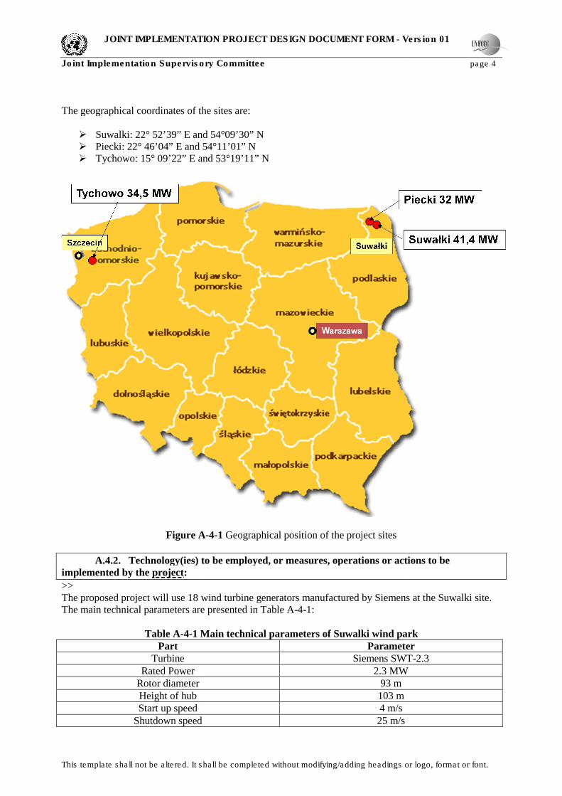
Anthropogenic emissions of greenhouse gases are to be reduced due to use of renewable power
generation. It implies emission reductions due to substitution of electricity from the national grid, which
has a high carbon intensity factor of 0.812 tCO2e/MWh1.
In 2010, almost 90 % of the electricity has been generated by coal-fired and lignite-fired power plants,
whereas the electricity generated by wind power plants or other types of renewable energy only amounts
to around 3.5 % (including hydroelectric power plants).
Figure A-4-2 Share in the domestic electricity production in Poland, by fuel type in 20102
Taking into account a number of significant technological barriers, connected with renewable energy,
other barriers described in details in Section B and the fact that renewable energy is not a common
practice in Poland, it is concluded that emission reductions would not occur in the absence of the
proposed project.
1 Source: http://www.kobize.pl/materialy/jicdm/JI-wskaznik_referencyjny_26sie2011_publik.pdf
2 Source: http://www.pse-operator.pl/uploads/kontener/raport_pse_2010_en.pdf
JOINT IMPLEMENTATION PROJECT DESIGN DOCUMENT FORM - Version 01
Joint Implementation Supervisory Committee page 7
This template shall not be altered. It shall be completed without modifying/adding headings or logo, format or font.
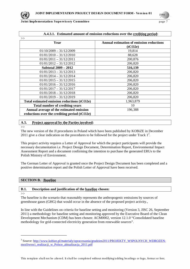
A.4.3.1. Estimated amount of emission reductions over the crediting period:
>>
Year Annual estimation of emission reductions
(tCO2e)
01/10/2009 – 31/12/2009 19,814
01/01/2010 – 31/12/2010 88,628
01/01/2011 – 31/12/2011 200,876
01/01/2012 – 31/12/2012 206,820
Subtotal 2009 – 2012 516,139
01/01/2013 – 31/12/2013 206,820
01/01/2014 – 31/12/2014 206,820
01/01/2015 – 31/12/2015 206,820
01/01/2016 – 31/12/2016 206,820
01/01/2017 – 31/12/2017 206,820
01/01/2018 – 31/12/2018 206,820
01/01/2019 – 31/12/2019 206,820
Total estimated emission reductions (tCO2e) 1,963,879
Total number of crediting years 10
Annual average of the estimated emission
reductions over the crediting period (tCO2e)
196,388
A.5. Project approval by the Parties involved:
>>
The new version of the JI procedures in Poland which have been published by KOBiZE in December
2011 give a clear indication on the procedures to be followed for the project under Track 13.
This project activity requires a Letter of Approval for which the project participants will provide the
necessary documentation i.e. Project Design Document, Determination Report, Environmental Impact
Assessment Report and a document confirming the intention to purchase the generated ERUs to the
Polish Ministry of Environment.
The German Letter of Approval is granted once the Project Design Document has been completed and a
positive determination report and the Polish Letter of Approval have been received.
SECTION B. Baseline
B.1. Description and justification of the baseline chosen:
>>
The baseline is the scenario that reasonably represents the anthropogenic emissions by sources of
greenhouse gases (GHG) that would occur in the absence of the proposed project activity.,
In line with the Guidelines on criteria for baseline setting and monitoring (Version 3, JISC 26, September
2011) a methodology for baseline setting and monitoring approved by the Executive Board of the Clean
Development Mechanism (CDM) has been chosen: ACM0002, version 12.1.0 “Consolidated baseline
methodology for grid-connected electricity generation from renewable sources”.
3 Source: http://www.kobize.pl/materialy/opracowania/grudzien2011/PROJEKTY_WSPOLNYCH_WDROZEN-
mozliwosci_realizacji_w_Polsce_aktualizacja_2011.pdf

JOINT IMPLEMENTATION PROJECT DESIGN DOCUMENT FORM - Version 01
Joint Implementation Supervisory Committee page 8
This template shall not be altered. It shall be completed without modifying/adding headings or logo, format or font.
Table B-1-1. Applicability of the baseline methodology ACM0002
ACM0002 Applicability Criteria Project Characteristics
The project activity is the installation, capacity
addition, retrofit or replacement of a power
plant/unit of one of the following types: hydro
power plant/unit (either with a run-of-river
reservoir or an accumulation reservoir), wind
power plant/unit, geothermal power plant/unit,
solar power plant/unit, wave power plant/unit or
tidal power plant/unit.
The project is the installation of a wind power
plant. Therefore this criteria can be seen as
fulfilled.
In the case of capacity additions, retrofits or
replacements (except for wind, solar, wave or tidal
power capacity addition projects which use Option
2: on page 11 to calculate the parameter
EGPJ,y): the existing plant started commercial
operation prior to the start of a minimum historical
reference period of five years, used for the
calculation of baseline emissions and defined in
the baseline emission section, and no capacity
expansion or retrofit of the plant has been
undertaken between the start of this minimum
historical reference period and the implementation
of the project activity.
As the project is a wind power plant this criteria is
not applicable.
In case of hydro power plants, one of the
following conditions must apply:
o The project activity is implemented in an
existing reservoir, with no change in the volume
of reservoir; or
o The project activity is implemented in an
existing reservoir, where the volume of reservoir
is increased and the power density of the project
activity, as per definitions given in the
Project Emissions section, is greater than 4 W/m2;
or
o The project activity results in new reservoirs and
the power density of the power plant, as
per definitions given in the Project Emissions
section, is greater than 4 W/m2.
The project is a wind power plant. Therefore this
criteria is not applicable.
´
Step 1: Identify realistic and credible alternative baseline scenarios for power generation Alternative 1: The proposed project activity is undertaken without being registered as a JI project.
Alternative 2: Construction of a fuel-fired power plant with equivalent amount of annual electricity
output.
Alternative 3: Construction of a power plant using other sources of renewable energy with equivalent
amount of annual electricity output.
Alternative 4: Electricity delivered to the Polish Grid by the project activity would have otherwise been
generated by the operation of grid-connected power plants and by the addition of new generation sources.
The utilizing hours and stability of wind power are of great difference from that of thermal power. The
total installed capacity in the Polish Power System as of 31 December 2007 amounted to 35,096 MW,
slightly more than in the previous year (by 232 MW). At the end of 2007, the total maximum capacity of
JOINT IMPLEMENTATION PROJECT DESIGN DOCUMENT FORM - Version 01
Joint Implementation Supervisory Committee page 9
This template shall not be altered. It shall be completed without modifying/adding headings or logo, format or font.
the public thermal power plants amounted to 30,147 MW and represented 86 % of the total maximum
capacity of the power system.4
Sub-step 1b. Enforcement of mandatory laws and regulations. Development of renewable energies is one of the priorities listed in the document called “Energy Policy
until 2030”, adopted by the Polish Government on 10 November 2009. It provides for mechanisms that
are intended to encourage the development of renewable energy power plants such as:
- exemption of the green power from excise tax (already in force);
- green certificates and the relevant mechanisms supporting green power producers (already in
force);
- tax support tools (some tax relieves have already been introduced);
- support of RES projects from the EU and environment protection funds.5
Therefore, the alternative 3 complies with the Polish laws and regulations. However, due to the
technology development status and the high cost for power generation, solar PV, biomass or geothermal
power stations of similar installed capacity as the proposed project are not realistic alternatives in Poland.
The proposed project is located in areas which lack hydropower resources, thus the alternative 3 is not
feasible.
Polish government has promulgated laws and regulations to support the renewable energy project which
includes the wind power project, thus the alternative 1 complies with Polish current laws and regulations.
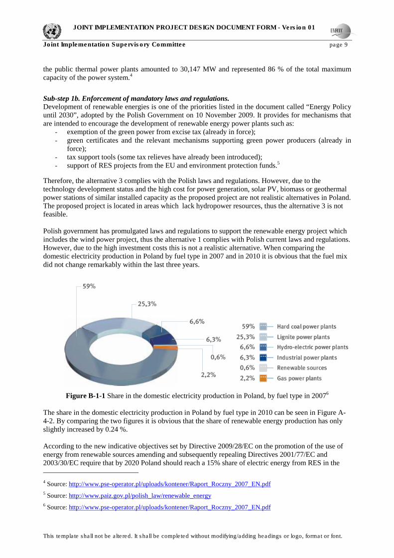
However, due to the high investment costs this is not a realistic alternative. When comparing the
domestic electricity production in Poland by fuel type in 2007 and in 2010 it is obvious that the fuel mix
did not change remarkably within the last three years.
Figure B-1-1 Share in the domestic electricity production in Poland, by fuel type in 2007
6
The share in the domestic electricity production in Poland by fuel type in 2010 can be seen in Figure A-
4-2. By comparing the two figures it is obvious that the share of renewable energy production has only
slightly increased by 0.24 %.
According to the new indicative objectives set by Directive 2009/28/EC on the promotion of the use of
energy from renewable sources amending and subsequently repealing Directives 2001/77/EC and
2003/30/EC require that by 2020 Poland should reach a 15% share of electric energy from RES in the
4 Source: http://www.pse-operator.pl/uploads/kontener/Raport_Roczny_2007_EN.pdf
5 Source: http://www.paiz.gov.pl/polish_law/renewable_energy
6 Source: http://www.pse-operator.pl/uploads/kontener/Raport_Roczny_2007_EN.pdf

JOINT IMPLEMENTATION PROJECT DESIGN DOCUMENT FORM - Version 01
Joint Implementation Supervisory Committee page 10
This template shall not be altered. It shall be completed without modifying/adding headings or logo, format or font.
gross consumption of electric energy.7 Alternative 2 would mean the construction of a fuel-fired power
plant with equivalent amount of annual electricity output which would not be consistent with the aims of
the Polish energy development. Therefore this alternative is to be considered as not feasible.
Alternative 4 is in compliance with all mandatory laws and regulations in Polish and faces with no
economical barriers. Furthermore, the annual electricity output of the Polish Grid has been increasing
steadily, as can be seen in Figure B-1-2 below:
Figure B-1-2 Production of electricity in 1951 – 2008
8
Hence, the Alternative 4 is a credible and realistic alternative. As a result, providing the same electricity
output by the Polish Grid is selected as the baseline scenario for the proposed project.
Step 2: Barrier Analysis As already mentioned in the Figures A-4-2 and B-1-1 wind power is not a prevailing practice in Poland.
Hence the fact that existing experience is limited to designing, building and operating wind farms does
represent a barrier to implementation of such a project activity. Furthermore, the project faced
technological barriers, as well as administrative barriers due to this lack of expertise in dealing with
renewable energies.
Among the technical barriers, the most severe ones are the barriers linked to grid connection and access,
not in terms of the physical connection but in terms of limited priority access with regard to fossil power
production and insufficient transport capacity linked to obsolete infrastructure.
This information is confirmed by a study undertaken in the name of the European Commision regarding
the “Assessment of non-cost barriers to renewable energy growth in EU Member States” in May 2010.9
7 Source: http://www.paiz.gov.pl/polish_law/renewable_energy
8 Source: http://www.pse-operator.pl/uploads/kontener/Raport_Roczny_2008_EN.pdf
9 Source: http://ec.europa.eu/energy/renewables/studies/doc/renewables/2010_non_cost_barriers.pdf

JOINT IMPLEMENTATION PROJECT DESIGN DOCUMENT FORM - Version 01
Joint Implementation Supervisory Committee page 11
This template shall not be altered. It shall be completed without modifying/adding headings or logo, format or font.
Furthermore, an assessment especially for Poland has been undertaken10
which also states this issue
within Section 7.2 as the most significant barrier in Poland.
The main problem is that the existing transmission and distribution networks are not able to provide grid
access to all renewable energy sources, as there are more applications for connection than the grid is able
to accept. The infrastructure of the Polish electricity grid has not been modernised properly during the
last two decades and therefore the grid is heavily overloaded. As a consequence, a significant number of
applications for a connection to the grid are rejected.
In order to expand the existing electricity infrastructure new overhead lines have to be constructed but
the owners of the land through which these lines are planned to pass are strongly opposed to this
construction. They fear that the value of their real estate decreases or ask for high indemnities.
Furthermore, the bearing and sharing of the costs for the grid extension is not transparent which prolongs
the whole process of grid expansion.
Apart from the technological barriers there are administrative barriers for wind farms in Poland. As the
market for wind energy is still relatively new there are a lot of insufficient administrative procedures and
a lack of transparency and guidelines. The main administrative barriers are:
- a lack of transparency in the application and decision-making process for authorising grid
connection
- badly defined requirements for the Environmental Impact Assessment (EIA) process (especially
for sites located close to Natura 2000 areas), the spatial planning permission and the grid
connection process
- obtaining the building permits e.g. for installation of masts for wind measurements and
development of wind farms
These barriers are also recognized by the Polish Wind Energy Association (PWEA)11
and due to these
the development of wind farms in Poland is associated with high risks. As a wind farm developer one has
to plan the time schedule and the expected costs for the project. However, this is very difficult in Poland
as the application and decision-making processes for the grid connection are not transparent and vary
from project application to project application. The unclear definitions for EIAs also form a part of this
problem because developers are often required to submit additional, time-consuming information at a
later stage which leads to a delay in the whole process. It could also happen that the same document is
accepted by one authority and questioned by another. The assessment of the wind farm’s impact on
protected bird species migration is reported to be a problem. Regarding the spatial planning the main
issue is that currently only 20% of the Polish area is covered with local spatial development plans. In
case such a plan is not in place the investor is obliged to obtain a “conditions on the site’s development”
decision which defines what facility can be implemented under which conditions. This means a
prolongation of the initiation phase of the project.
Obtaining a building permit often takes a long time in Poland due to public consultation and the time lag
in decisions of local authorities which might be caused due to a lack of knowledge and benefits of
renewable energies. In the worst case, all this time delays can lead to the failure of a project.
Once the project is installed there are more barriers one has to face. Firstly, there is no priority
evacuation for renewable energy as it is the case in Germany and therefore the future of the grid supply
relies heavily on the grid operator. Secondly, there is a lack of certification bodies and trainings for the
education of installers, planners etc. for renewable energies. In Poland there is no implemented system
for the certification and accreditation of installers of equipment as defined in the regulation of the
European Commission. There is also no certification body for wind power which would secure trainings
or the assessment of quality of the system or the equipment.
10 Source: http://ec.europa.eu/energy/renewables/studies/doc/renewables/2010_non_cost_barriers_countries.zip
11 Source: http://www.wind-energy-the-facts.org/en/part-4-industry--markets/chapter-5-administrative-and-grid-
access-barriers---an-analysis-of-existing-eu-studies-in-the-field/case-studies
JOINT IMPLEMENTATION PROJECT DESIGN DOCUMENT FORM - Version 01
Joint Implementation Supervisory Committee page 12
This template shall not be altered. It shall be completed without modifying/adding headings or logo, format or font.
Step 3: Common Practice Analysis As already stated above wind energy is not common practice in Poland. Prevailing practice is the
electrictiy generation by fossil fuels as hard coal and lignite. Even though in 2005 the Polish Energy Law
Act was amended to provide a quota system obligation in the form of a “Green Certificate System”12
the
production of electricity through renewable energies did not increase noticeably. In 2010, almost 90 % of
the electricity has still been generated by coal-fired and lignite-fired power plants, whereas the electricity
generated by wind power plants or other types of renewable energy only amounts to around 3.5 %
(including hydroelectric power plants) as can be seen in Figure A-4-2 above.
Step 4: Conclusion The proposed project faces significant technical, administrative and prevailing practice barriers which
place a huge impact on the decision making process. With the help of carbon credits these barriers are
alleviated as they improve the project financially. Hence the wind park activity is additional.
B.2. Description of how the anthropogenic emissions of greenhouse gases by sources are
reduced below those that would have occurred in the absence of the JI project:
>>
Calculation of baseline emissions (BEy) BEy = EG PJ, y x EFgrid, CM, y
Where:
BEy = Baseline emissions in year y
EG PJ, y = Quantity of net electricity generation that is produced and fed into the grid as a result
of the implementation of the JI project activity in year y (MWh/yr)
EFgrid, CM, y = Combined margin CO2 emission factor for grid connected power generation in year y
Calculation of EG PJ, y
For greenfield renewable energy power plants the quantity of net electricity generation that is produced
and fed into the grid is equal to the quantity of net electricity generation supplied by the project plant
EG PJ, y = EGfacility, y
Calculation of EFgrid, CM, y
The calculation of the grid emission factor is not necessary as this factor is officially regulated by the
Polish government13
:
EFgrid, CM, y = 0,812 tCO2/MWh
Calculation of Leakage According to ACM0002, version 12.1.0 no leakage emissions are to be considered. The main emissions
potentially giving rise to leakage in the context of electric sector projects are emissions arising due to
activities such as power plant construction and upstream emissions from fossil fuel use (e.g. extraction,
processing, transport). These emission sources are neglected.
LEy = 0
Project Emissions According to ACM0002, version 12.1.0 the project emissions for renewable power generation project
activities are to be considered as zero except the project activity uses fossil fuels as a back up technology,
12 Source: http://www.iea.org/textbase/pm/?mode=pm&id=3675&action=detail
13 Source: http://www.kobize.pl/materialy/jicdm/JI-wskaznik_referencyjny_26sie2011_publik.pdf

JOINT IMPLEMENTATION PROJECT DESIGN DOCUMENT FORM - Version 01
Joint Implementation Supervisory Committee page 13
This template shall not be altered. It shall be completed without modifying/adding headings or logo, format or font.
the project activity is a geothermal power plant or the project activity is a hydropower plant with a
reservoir.
As this project activity is a wind power plant the project emissions can be defined as:
PEy = 0
Emission Reductions ERy = BEy - PEy
Where:
ERy = Emission Reductions in year y (tCO2e/yr)
BEy = Baseline emissions in year y (tCO2/yr)
PEy = Project emissions in year y (tCO2e/yr)
Data and parameters not monitored
Data / Parameter: EFgrid,CM,y
Data unit: tCO2/MWh
Description: Combined margin CO2 emission factor for grid connected power generation in
year y regulated by the Polish government
Source of data: http://www.kobize.pl/materialy/jicdm/JI-
wskaznik_referencyjny_26sie2011_publik.pdf
Measurement
procedures (if any):
-
Monitoring
frequency:
-
QA/QC procedures: -
Any comment: -
Data and parameters monitored
Data / Parameter: EGfacility,y
Data unit: MWh/yr
Description: Quantity of net electricity generation supplied by the project plant/unit to the grid
in year y
Source of data: Project activity sites Suwalki, Piecki and Tychowo
Measurement
procedures (if any):
Electricity meters
Monitoring
frequency:
Continuous measurement and at least monthly recording
QA/QC procedures: Cross check measurement results with records for sold electricity
Any comment: -

JOINT IMPLEMENTATION PROJECT DESIGN DOCUMENT FORM - Version 01
Joint Implementation Supervisory Committee page 14
This template shall not be altered. It shall be completed without modifying/adding headings or logo, format or font.
B.3. Description of how the definition of the project boundary is applied to the project:
>>
The project boundary is defined as being the Polish electricity grid which is operated by the state-owned
Polskie Sieci Elektroenergetyczne (PSE) Operator S.A..
The following three subsystems are distinguished in the Polish Power System (PPS), because of the
nature of the technical functions:
- generation of electricity (at power plants, heat and power plants and distributed generation);
- transmission of electricity through the extra-high voltage power network nation-wide and via
crossborder lines through the Polish borders (the task is executed by PSE as the transmission
system operator);
- distribution of electricity through the high, medium and low voltage distribution networks (the
task is executed by 20 different distribution system operators).
Figure B-3-1 Polish Transmission System
14
14 Source: http://www.pse-operator.pl/uploads/kontener/Raport_Roczny_2007_EN.pdf
JOINT IMPLEMENTATION PROJECT DESIGN DOCUMENT FORM - Version 01
Joint Implementation Supervisory Committee page 15
This template shall not be altered. It shall be completed without modifying/adding headings or logo, format or font.
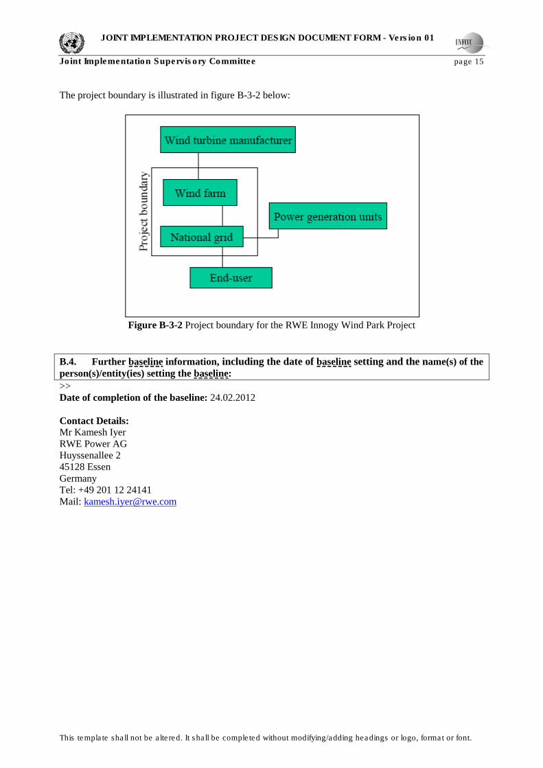
The project boundary is illustrated in figure B-3-2 below:
Figure B-3-2 Project boundary for the RWE Innogy Wind Park Project
B.4. Further baseline information, including the date of baseline setting and the name(s) of the
person(s)/entity(ies) setting the baseline:
>>
Date of completion of the baseline: 24.02.2012
Contact Details: Mr Kamesh Iyer
RWE Power AG
Huyssenallee 2
45128 Essen
Germany
Tel: +49 201 12 24141
Mail: [email protected]

JOINT IMPLEMENTATION PROJECT DESIGN DOCUMENT FORM - Version 01
Joint Implementation Supervisory Committee page 16
This template shall not be altered. It shall be completed without modifying/adding headings or logo, format or font.
SECTION C. Duration of the project / crediting period
C.1. Starting date of the project:
>>
The starting date of the project activity is 31.03.2008 which is the date of the Turbine Supply Agreement
with Siemens Wind Power GmbH for site no 1 (Suwalki).
C.2. Expected operational lifetime of the project:
>>
20 years
C.3. Length of the crediting period:
>>
The start of the crediting period for the proposed project activity is 1st October 2009 which is the date of
commissioning of the first project site at Suwalki.
The end of the first commitment period is 31st December 2012.
The end of the crediting period is 31st December 2019.
JOINT IMPLEMENTATION PROJECT DESIGN DOCUMENT FORM - Version 01
Joint Implementation Supervisory Committee page
17
This template shall not be altered. It shall be completed without modifying/adding headings or logo, format or font.
SECTION D. Monitoring plan
D.1. Description of monitoring plan chosen:
>>
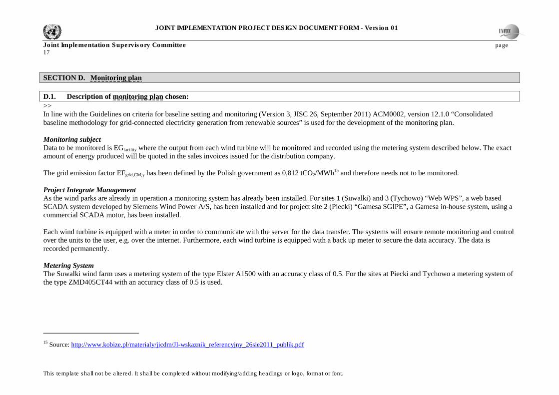
In line with the Guidelines on criteria for baseline setting and monitoring (Version 3, JISC 26, September 2011) ACM0002, version 12.1.0 “Consolidated
baseline methodology for grid-connected electricity generation from renewable sources” is used for the development of the monitoring plan.
Monitoring subject Data to be monitored is EGfacility where the output from each wind turbine will be monitored and recorded using the metering system described below. The exact
amount of energy produced will be quoted in the sales invoices issued for the distribution company.
The grid emission factor EFgrid,CM,y has been defined by the Polish government as 0,812 tCO2/MWh15
and therefore needs not to be monitored.
Project Integrate Management As the wind parks are already in operation a monitoring system has already been installed. For sites 1 (Suwalki) and 3 (Tychowo) “Web WPS”, a web based
SCADA system developed by Siemens Wind Power A/S, has been installed and for project site 2 (Piecki) “Gamesa SGIPE”, a Gamesa in-house system, using a
commercial SCADA motor, has been installed.
Each wind turbine is equipped with a meter in order to communicate with the server for the data transfer. The systems will ensure remote monitoring and control
over the units to the user, e.g. over the internet. Furthermore, each wind turbine is equipped with a back up meter to secure the data accuracy. The data is
recorded permanently.
Metering System The Suwalki wind farm uses a metering system of the type Elster A1500 with an accuracy class of 0.5. For the sites at Piecki and Tychowo a metering system of
the type ZMD405CT44 with an accuracy class of 0.5 is used.
15 Source: http://www.kobize.pl/materialy/jicdm/JI-wskaznik_referencyjny_26sie2011_publik.pdf

JOINT IMPLEMENTATION PROJECT DESIGN DOCUMENT FORM - Version 01
Joint Implementation Supervisory Committee page
18
This template shall not be altered. It shall be completed without modifying/adding headings or logo, format or font.
The serial numbers of the individual meters are as follows:
Suwalki Piecki Tychowo
Turbine Serial no. Turbine Serial no. Turbine Serial no.
WTG 1 00-371492 WTG 1 96492289 WTG 1 96.475.887
WTG 2 00-371486 WTG 2 96492290 WTG 2 96.573.402
WTG 3 00-371483 WTG 3 96492299 WTG 3 96.508.241
WTG 4 00-371496 WTG 4 96492298 WTG 4 96.475.877
WTG 5 00-371490 WTG 5 96492296 WTG 5 96.508.233
WTG 6 00-371498 WTG 6 96492294 WTG 6 96.475.888
WTG 7 00-371501 WTG 7 96492291 WTG 7 96.508.236
WTG 8 00-371497 WTG 8 96492297 WTG 8 96.508.237
WTG 9 00-371485 WTG 9 96492301 WTG 9 96.508.234
WTG 10 00-371494 WTG 10 96492302 WTG 10 96.475.889
WTG 11 00-371500 WTG 11 96492295 WTG 11 96.508.240
WTG 12 00-371495 WTG 12 96492300 WTG 12 96.508.242
WTG 13 00-367338 WTG 13 96492288 WTG 13 96.508.238
WTG 14 00-371487 WTG 14 96492292 WTG 14 96.508.235
WTG 15 00-367343 WTG 15 96492287 WTG 15 96.508.239
WTG 16 00-371484 WTG 16 96492293
WTG 17 00-355342
WTG 18 00-371493
The metering system will be calibrated every two years by the grid operator PSE, according to the Polish energy regulations.

JOINT IMPLEMENTATION PROJECT DESIGN DOCUMENT FORM - Version 01
Joint Implementation Supervisory Committee page
19
This template shall not be altered. It shall be completed without modifying/adding headings or logo, format or font.
D.1.1. Option 1 – Monitoring of the emissions in the project scenario and the baseline scenario:
D.1.1.2. Description of formulae used to estimate project emissions (for each gas, source etc.; emissions in units of CO2 equivalent):
>>
D.1.1.3. Relevant data necessary for determining the baseline of anthropogenic emissions of greenhouse gases by sources within the
project boundary, and how such data will be collected and archived: ID number Data
variable
Source of data Data unit Measured (m),
calculated (c),
estimated (e)
Recording
frequency
Proportion
of data to be
monitored
How will the data
be archived?
(electronic/paper)
Comment
EGfacility Electricity Electricity
supplied to the
grid
MWh m Permanent
measurement
and monthly
recording
100% Electronic Directly measured using software application
supporting the wind farm management.
Double checked through manual check of
data on every meter and against the receipt of
sales (distribution company will be invoiced
every month). Furthermore, each wind
turbine is equipped with a back up meter to
secure the data accuracy.
There are responsible persons for each site
who take care of the data collection and
control on a monthly basis. These are
employed directly by RWE Renewables
Polska, the company operating the wind park.
D.1.1.4. Description of formulae used to estimate baseline emissions (for each gas, source etc.; emissions in units of CO2 equivalent):
>>
BEy = EG PJ, y x EFgrid, CM, y
Where:
BEy = Baseline emissions in year y
EG PJ, y = Quantity of net electricity generation that is produced and fed into the grid as a result
of the implementation of the JI project activity in year y (MWh/yr)
EFgrid, CM, y = Combined margin CO2 emission factor for grid connected power generation in year y

JOINT IMPLEMENTATION PROJECT DESIGN DOCUMENT FORM - Version 01
Joint Implementation Supervisory Committee page
20
This template shall not be altered. It shall be completed without modifying/adding headings or logo, format or font.
Calculation of EG PJ, y
For greenfield renewable energy power plants the quantity of net electricity generation that is produced and fed into the grid is equal to the quantity of net
electricity generation supplied by the project plant
EG PJ, y = EGfacility, y
Calculation of EFgrid, CM, y
The calculation of the grid emission factor is not necessary as this factor is officially regulated by the Polish government16
:
EFgrid, CM, y = 0,812 tCO2/MWh
D. 1.2. Option 2 – Direct monitoring of emission reductions from the project (values should be consistent with those in section E.):
>>
D.1.2.1. Data to be collected in order to monitor emission reductions from the project, and how these data will be archived: ID number Data variable Source of data Data unit Measured (m),
calculated (c),
estimated (e)
Recording
frequency
Proportion of
data to be
monitored
How will the
data be
archived?
(electronic/
paper)
Comment
EFgrid,CM,y Grid emission
factor
GHG emission
factor of the
Polish grid
tCO2/MWh Fixed by the
Polish
government
- - - The grid
emission factor
has been defined
by the Polish
government as
0.812
tCO2/MWh17
.
16 Source: http://www.kobize.pl/materialy/jicdm/JI-wskaznik_referencyjny_26sie2011_publik.pdf
17 http://www.kobize.pl/materialy/jicdm/JI-wskaznik_referencyjny_26sie2011_publik.pdf

JOINT IMPLEMENTATION PROJECT DESIGN DOCUMENT FORM - Version 01
Joint Implementation Supervisory Committee page
21
This template shall not be altered. It shall be completed without modifying/adding headings or logo, format or font.
D.1.2.2. Description of formulae used to calculate emission reductions from the project (for each gas, source etc.; emissions/emission
reductions in units of CO2 equivalent):
>>
ERy = BEy - PEy
Where:
ERy = Emission Reductions in year y (tCO2e/yr)
BEy = Baseline emissions in year y (tCO2/yr)
PEy = Project emissions in year y (tCO2e/yr)
D.1.3. Treatment of leakage in the monitoring plan:
>>
According to ACM0002, version 12.1.0 no leakage emissions are to be considered. The main emissions potentially giving rise to leakage in the context of
electric sector projects are emissions arising due to activities such as power plant construction and upstream emissions from fossil fuel use (e.g. extraction,
processing, transport). These emission sources are neglected.
LEy = 0
D.1.3.2. Description of formulae used to estimate leakage (for each gas, source etc.; emissions in units of CO2 equivalent):
>>
Please refer to Secion D.1.3.
D.1.4. Description of formulae used to estimate emission reductions for the project (for each gas, source etc.; emissions/emission reductions in
units of CO2 equivalent):
>>
ERy = BEy - PEy
Where:
ERy = Emission Reductions in year y (tCO2e/yr)
BEy = Baseline emissions in year y (tCO2/yr)
PEy = Project emissions in year y (tCO2e/yr)

JOINT IMPLEMENTATION PROJECT DESIGN DOCUMENT FORM - Version 01
Joint Implementation Supervisory Committee page
22
This template shall not be altered. It shall be completed without modifying/adding headings or logo, format or font.
D.1.5. Where applicable, in accordance with procedures as required by the host Party, information on the collection and archiving of
information on the environmental impacts of the project:
>>
Please refer to Section F. Environmental Impacts.
D.2. Quality control (QC) and quality assurance (QA) procedures undertaken for data monitored: Data Uncertainty level of data
(high/medium/low)
Explain QA/QC procedures planned for these data, or why such procedures are not necessary.
EGfacility Low Directly measured using software application supporting the wind farm management. Double checked through manual
check of data on every meter and against the receipt of sales (distribution company will be invoiced every month).
Furthermore, each wind turbine is equipped with a back up meter to secure the data accuracy.
There are responsible persons for each site who take care of the data collection and control on a monthly basis. These
are employed directly by RWE Renewables Polska, the company operating the wind park.
D.3. Please describe the operational and management structure that the project operator will apply in implementing the monitoring plan:
>>
An efficient operational and management structure as already been implemented for monitoring the project. On each site there are responsible persons who take
care of the data collection and control. They do not only check the data that has been recorded by the Scada System but do also check the data directly at the
monitoring meters at the end of the month. These people are employed by RWE Renewables Polska, the operator of the wind farms and are therefore familiar
with the technical equipments.
D.4. Name of person(s)/entity(ies) establishing the monitoring plan:
>>
Date: 24.02.2012
Contact Details:
Mr Kamesh Iyer
RWE Power AG
Huyssenallee 2
45128 Essen
Germany
Tel: +49 201 12 24141
Mail: [email protected]

JOINT IMPLEMENTATION PROJECT DESIGN DOCUMENT FORM - Version 01
Joint Implementation Supervisory Committee page 23
This template shall not be altered. It shall be completed without modifying/adding headings or logo, format or font.
SECTION E. Estimation of greenhouse gas emission reductions
E.1. Estimated project emissions:
>>
According to ACM0002, version 12.1.0 the project emissions for renewable power generation project
activities are to be considered as zero except the project activity uses fossil fuels as a back up technology,
the project activity is a geothermal power plant or the project activity is a hydropower plant with a
reservoir.
As this project activity is a wind power plant the project emissions can be defined as: PEy = 0
E.2. Estimated leakage:
>>
According to ACM0002, version 12.1.0 no leakage emissions are to be considered. The main emissions
potentially giving rise to leakage in the context of electric sector projects are emissions arising due to
activities such as power plant construction and upstream emissions from fossil fuel use (e.g. extraction,
processing, transport). These emission sources are neglected.
LEy = 0
E.3. The sum of E.1. and E.2.:
>>
As both values are considered as zero, the sum of E.1. and E.2. is also to be considered as zero.
PEy + LEy = 0
E.4. Estimated baseline emissions:
>>
The estimated baseline emissions have been calculated as following:
BEy = EG PJ, y · EFgrid, CM, y
Where:
BEy = Baseline emissions in year y
EG PJ, y = Quantity of net electricity generation that is produced and fed into the grid as a result
of the implementation of the JI project activity in year y (MWh/yr)
EFgrid, CM, y = Combined margin CO2 emission factor for grid connected power generation in year y
Calculation of EG PJ, y
For greenfield renewable energy power plants the quantity of net electricity generation that is produced
and fed into the grid is equal to the quantity of net electricity generation supplied by the project plant
EG PJ, y = EGfacility, y
Calculation of EFgrid, CM, y
The calculation of the grid emission factor is not necessary as this factor is officially regulated by the
Polish government18
:
EFgrid, CM, y = 0.812 tCO2/MWh
18 Source: http://www.kobize.pl/materialy/jicdm/JI-wskaznik_referencyjny_26sie2011_publik.pdf

JOINT IMPLEMENTATION PROJECT DESIGN DOCUMENT FORM - Version 01
Joint Implementation Supervisory Committee page 24
This template shall not be altered. It shall be completed without modifying/adding headings or logo, format or font.
According to the RWE internal business cases the following quantities of electricity generation have
been estimated:
- Suwalki: 97,607 MWh/y
- Piecki: 69,248 MWh/y
- Tychowo: 87,850 MWh/y
Therefore the total estimated annual electricity generation amounts to 254,705 MWh/y, once all the sites
have been put into operation. The commissioning dates of the different sites are as followed:
- Suwalki: October 2009
- Piecki: November 2010
- Tychowo: February 2011
As a result the estimated electrity generation only amounts to 2,418,574 MWh for the whole crediting
period from 01/10/2009 until 31/12/2019. The baseline emissions for the crediting period are calculated
as following:
2,418,574 · 0.812 = 1,963,879 tCO2e
E.5. Difference between E.4. and E.3. representing the emission reductions of the project:
>>
As the project emissions and the leakage is to be considered as zero, the emission reductions are equal to
the baseline emissions i.e. 1,963,879 tCO2e.
E.6. Table providing values obtained when applying formulae above:
>>
Year
Estimated
project emissions
(tCO2e)
Estimated
leakage
(tCO2e)
Estimated
baseline
emissions (tCO2e)
Estimated
emission
reductions
(tCO2e)
2009 0 0 19,814 19,814
2010 0 0 88,628 88,628
2011 0 0 200,876 200,876
2012 0 0 206,820 206,820
Subtotal 2009 –
2012 (tCO2e) 0 0 516,139 516,139
2013 0 0 206,820 206,820
2014 0 0 206,820 206,820
2015 0 0 206,820 206,820
2016 0 0 206,820 206,820
2017 0 0 206,820 206,820
2018 0 0 206,820 206,820
2019 0 0 206,820 206,820
Subtotal 2012 –
2019 (tCO2e) 0 0 1,447,740 1,447,740
Total 2009 – 2019
(tCO2e) 0 0 1,963,879 1,963,879

JOINT IMPLEMENTATION PROJECT DESIGN DOCUMENT FORM - Version 01
Joint Implementation Supervisory Committee page 25
This template shall not be altered. It shall be completed without modifying/adding headings or logo, format or font.
SECTION F. Environmental impacts
F.1. Documentation on the analysis of the environmental impacts of the project, including
transboundary impacts, in accordance with procedures as determined by the host Party:
>>
For all three sites an Environmental Impact Assessment (EIA) has been undertaken as detailed below:
Site Issued on Issuing Authority Consulted with
1 10.11.2006 Mayor of Municipality Suwalki Sanitary Inspection and Regional
Authority (Starosta Suwalski)
2 08.11.2007 Mayor of Municipality Piecki Sanitary Inspection and Regional
Authority (Starosta Suwalski)
3 10.11.2006 Mayor of Municipality Stargard
Szczeciński
Sanitary Inspection and Regional
Authority (Starosta Stargardzki and
Zachodniopomorski Urząd
Wojewódzki w Szczecinie)
There has been a public consultation procedure for 21 days during which the EIAs have been publicly
available and there has also been the possibility to raise comments and questions concerning the
installation of the wind park.
The EIAs concluded that none of the sites has significant impacts to the environment or any protected
areas.
F.2. If environmental impacts are considered significant by the project participants or the
host Party, please provide conclusions and all references to supporting documentation of an
environmental impact assessment undertaken in accordance with the procedures as required by
the host Party:
>>
Overall environmental impacts of the project activity will be positive in comparism with the baseline
scenario.
SECTION G. Stakeholders’ comments
G.1. Information on stakeholders’ comments on the project, as appropriate:
>>
Stakeholder comments will be collected after the publication of this document on the DOE’s web-page
during the determination procedure.
However, as a part of the EIA’s a detailed public consultation procedure has been undertaken for all 3
sites and no comments were received. So we conclude that these Windparks are in accordance with the
expectation of the relevant stakeholders and is deemed appropriate.
JOINT IMPLEMENTATION PROJECT DESIGN DOCUMENT FORM - Version 01
Joint Implementation Supervisory Committee page 26
This template shall not be altered. It shall be completed without modifying/adding headings or logo, format or font.
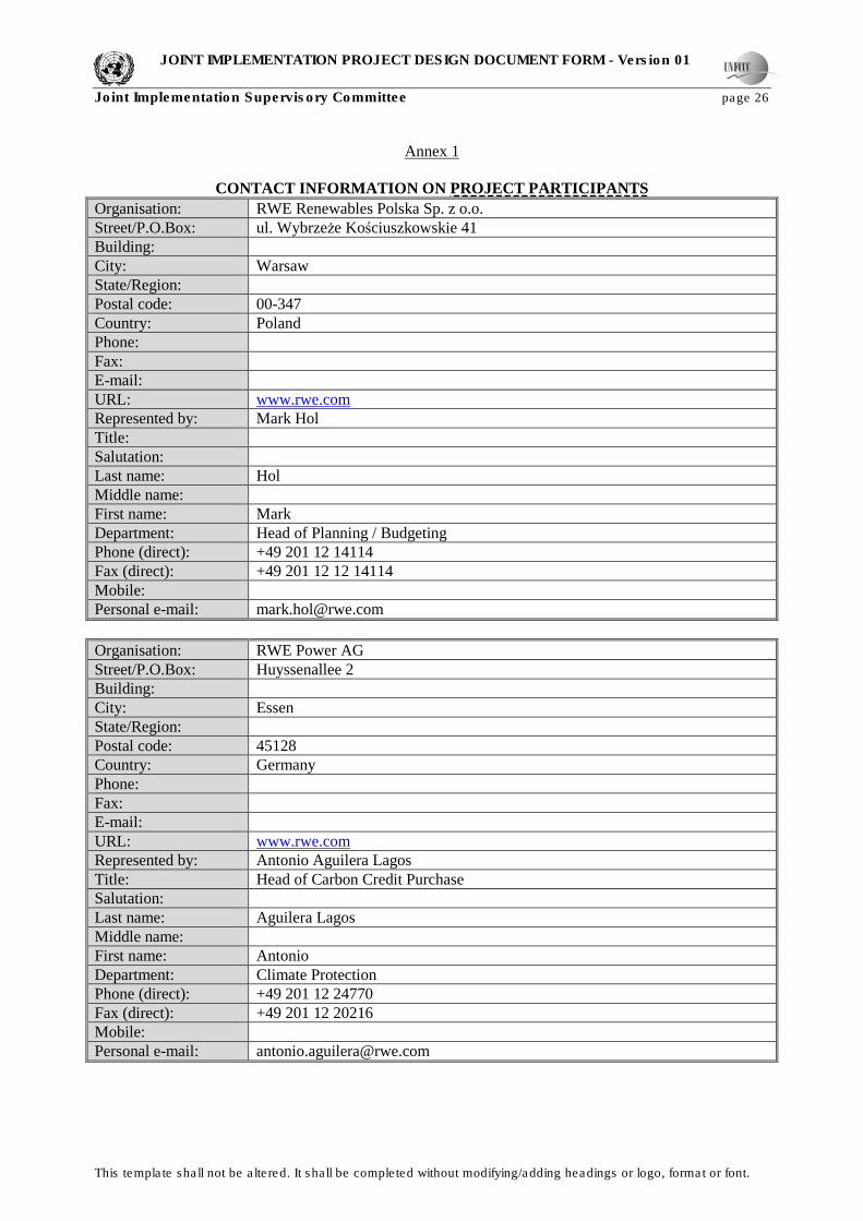
Annex 1
CONTACT INFORMATION ON PROJECT PARTICIPANTS
Organisation: RWE Renewables Polska Sp. z o.o.
Street/P.O.Box: ul. WybrzeŜe Kościuszkowskie 41
Building:
City: Warsaw
State/Region:
Postal code: 00-347
Country: Poland
Phone:
Fax:
E-mail:
URL: www.rwe.com
Represented by: Mark Hol
Title:
Salutation:
Last name: Hol
Middle name:
First name: Mark
Department: Head of Planning / Budgeting
Phone (direct): +49 201 12 14114
Fax (direct): +49 201 12 12 14114
Mobile:
Personal e-mail: [email protected]
Organisation: RWE Power AG
Street/P.O.Box: Huyssenallee 2
Building:
City: Essen
State/Region:
Postal code: 45128
Country: Germany
Phone:
Fax:
E-mail:
URL: www.rwe.com
Represented by: Antonio Aguilera Lagos
Title: Head of Carbon Credit Purchase
Salutation:
Last name: Aguilera Lagos
Middle name:
First name: Antonio
Department: Climate Protection
Phone (direct): +49 201 12 24770
Fax (direct): +49 201 12 20216
Mobile:
Personal e-mail: [email protected]

JOINT IMPLEMENTATION PROJECT DESIGN DOCUMENT FORM - Version 01
Joint Implementation Supervisory Committee page 27
This template shall not be altered. It shall be completed without modifying/adding headings or logo, format or font.
Annex 2
BASELINE INFORMATION
>>
Please refer to Section B. Baseline.

JOINT IMPLEMENTATION PROJECT DESIGN DOCUMENT FORM - Version 01
Joint Implementation Supervisory Committee page 28
This template shall not be altered. It shall be completed without modifying/adding headings or logo, format or font.
Annex 3
MONITORING PLAN
>> Please refer to Section D. Monitoring Plan.

JOINT IMPLEMENTATION PROJECT DESIGN DOCUMENT FORM - Version 01
Joint Implementation Supervisory Committee page 29
This template shall not be altered. It shall be completed without modifying/adding headings or logo, format or font.
Annex 4
FINANCIAL INFORMATION
>> All financial information is confidential and will be provided on request.