Embed Size (px)
Citation preview
A Subsidiary of
0
000
Joint Evaluation Report ESR-1144 Reissued 08/2018
This report is subject to renewal 08/2020.
ICC-ES | (800) 423-6587 | (562) 699-0543 | www.icc-es.org
ICC-ES Evaluation Reports are not to be construed as representing aesthetics or any other attributes not specifically addressed, nor are they to be construed as an endorsement of the subject of the report or a recommendation for its use. There is no warranty by ICC Evaluation Service, LLC, express or implied, as to any finding or other matter in this report, or as to any product covered by the report.
Copyright© 2018 ICC Evaluation Service, LLC and APA—The Engineered Wood Association. All rights reserved.
“2014 Recipient of Prestigious Western States Seismic Policy Council (WSSPC) Award in Excellence”
DIVISION: 06 00 00—WOOD, PLASTICS AND COMPOSITES SECTION: 06 17 33—WOOD I-JOISTS
REPORT HOLDER:
BOISE CASCADE WOOD PRODUCTS, LLC
EVALUATION SUBJECT:
AJS SERIES PREFABRICATED WOOD I-JOISTS
Look for the trusted marks of Conformity!
Joint Evaluation Report ESR-1144 Reissued August 2018 This report is subject to renewal August 2020.
www.icc-es.org | (800) 423-6587 | (562) 699-0543 A Subsidiary of the International Code Council®
DIVISION: 06 00 00—WOOD, PLASTICS AND
COMPOSITES Section: 06 17 33—Wood I-Joists REPORT HOLDER:
BOISE CASCADE WOOD PRODUCTS, LLC EVALUATION SUBJECT:
AJS SERIES PREFABRICATED WOOD I-JOISTS 1.0 EVALUATION SCOPE
Compliance with the following codes: 2015, 2012, 2009 and 2006 International Building
Code® (IBC) 2015, 2012, 2009 and 2006 International Residential
Code® (IRC) Property evaluated: Structural
2.0 USES AJS I-joists are prefabricated wood I-joists used as floor joists, roof rafters and blocking panels, to support code-required loads. Prefabricated wood I-joists described in this report comply with Section 2303.1.2 of the IBC and Section R502.1.2 of the 2015 IRC or Section R502.1.4 of the 2012 IRC, for allowable stress design.
3.0 DESCRIPTION 3.1 General: The AJS Series prefabricated wood I-joists have solid-sawn lumber or laminated veneer lumber flanges, and oriented strand board (OSB) webs. The top and bottom flanges are parallel, creating constant-depth joists. The web-to-web joints of the I-joists are square butt joints and conform to the specifications in the approved quality documentation. The web-to-flange connection is a proprietary grooved connection, also conforming to the approved quality documentation. Additionally, AJS I-joists are also manufactured with proprietary FireBreak HITS™ and Thermax™ fire protective materials factory-applied to both faces of the web, as specified in the approved quality documentation. The AJS I-joists are available in various lengths and depths. See Table 1 for a description of the I-joists. 3.2 Material Specifications: 3.2.1 Flanges: The flanges of the I-joists are sawn lumber or laminated veneer lumber (LVL) conforming to the specifications in the approved quality documentation.
The LVL lumber flanges are 11/2-inch-by-21/2-inch (38 by 64 mm) spruce-pine-fir (SPF) proprietary grade LVL and are used interchangeably with any of the sawn lumber flanges of the same dimensions. The sawn lumber flange material, grade, width and depth are noted in Table 1.
3.2.2 Web: Web material for the I-joists is 3/8-inch-thick (10 mm) or 7/16-inch-thick (11 mm) OSB conforming to Exposure 1 requirements of DOC PS-2, with further requirements set forth in the approved quality documentation and manufacturing standards.
3.2.3 Adhesive: Adhesives used in the fabrication of the I-joists are exterior-type, heat-durable adhesives complying with ASTM D2559 and ASTM D5055, and are specified in the quality documentation and the manufacturing standards.
4.0 DESIGN AND INSTALLATION
Design of the prefabricated wood I-joists described in this report must be in accordance with the applicable code. Additionally, the design and installation of the prefabricated wood I-joists must comply with Sections 4.1 through 4.13, and the manufacturer’s installation instructions.
4.1 Reference Design Values: The reference design moments, vertical shear capacity, I-joist stiffness (EI) , and reactions are specified in Table 2. Reference design end reactions are based on a minimum bearing length of 11/2 inches (38 mm) for simple spans on joists having depths of 91/4 to 16 inches (235 mm to 406 mm), and 13/4 inches (44.5 mm) on joists having depths of 18 inches (457 mm) or greater. Reference design intermediate reactions are based on a minimum bearing length of 31/2 inches (89 mm) at intermediate support points for continuous spans. Floor assemblies, consisting of a minimum 23/32-inch-thick (18 mm) Sturd-I-Floor rated sheathing nailed to the I-joists in accordance with the applicable code requirements and adhered to the top flanges of the I-joists using AFG-01 construction adhesive, have the allowable spans shown in Table 3.
4.2 Fasteners: Reference withdrawal design values and lateral load values, for nails installed into the flanges, must be determined in accordance with the applicable code, using a specific gravity of 0.42. Fastener spacing must comply with the minimum spacing requirements prescribed by the applicable code for nails installed in sawn lumber.
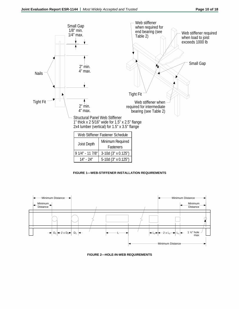
4.3 Web Stiffeners: Web stiffener requirements for the I-joists at reaction and concentrated load locations are noted in Figure 1.
ICC-ES Evaluation Reports are not to be construed as representing aesthetics or any other attributes not specifically addressed, nor are they to be construed as an endorsement of the subject of the report or a recommendation for its use. There is no warranty by ICC Evaluation Service, LLC, express or implied, as to any finding or other matter in this report, or as to any product covered by the report.
Copyright © 2018 ICC Evaluation Service, LLC and APA – The Engineered Wood Association. All rights reserved. Page 1 of 18
Joint Evaluation Report ESR-1144 | Most Widely Accepted and Trusted Page 2 of 18
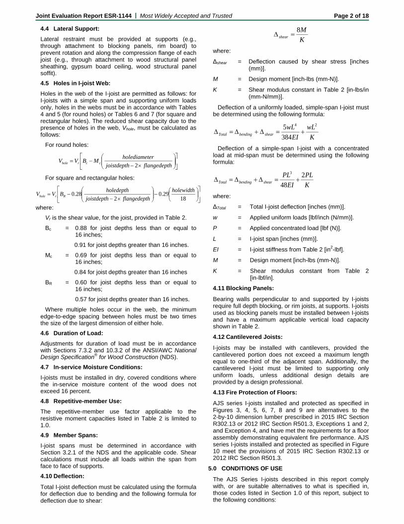
4.4 Lateral Support: Lateral restraint must be provided at supports (e.g., through attachment to blocking panels, rim board) to prevent rotation and along the compression flange of each joist (e.g., through attachment to wood structural panel sheathing, gypsum board ceiling, wood structural panel soffit). 4.5 Holes in I-joist Web: Holes in the web of the I-joist are permitted as follows: for I-joists with a simple span and supporting uniform loads only, holes in the webs must be in accordance with Tables 4 and 5 (for round holes) or Tables 6 and 7 (for square and rectangular holes). The reduced shear capacity due to the presence of holes in the web, Vhole, must be calculated as follows:
For round holes:
×−
−=hflangedeptjoistdepth
erholediametMBVV ccrhole 2
For square and rectangular holes:
−
×−
−=18
29.02
28.0 holewidthhflangedeptjoistdepth
holedepthBVV Rrhole
where: Vr is the shear value, for the joist, provided in Table 2.
Bc = 0.88 for joist depths less than or equal to 16 inches;
0.91 for joist depths greater than 16 inches.
Mc = 0.69 for joist depths less than or equal to 16 inches;
0.84 for joist depths greater than 16 inches
BR = 0.60 for joist depths less than or equal to 16 inches; 0.57 for joist depths greater than 16 inches.
Where multiple holes occur in the web, the minimum edge-to-edge spacing between holes must be two times the size of the largest dimension of either hole. 4.6 Duration of Load: Adjustments for duration of load must be in accordance with Sections 7.3.2 and 10.3.2 of the ANSI/AWC National Design Specification® for Wood Construction (NDS). 4.7 In-service Moisture Conditions: I-joists must be installed in dry, covered conditions where the in-service moisture content of the wood does not exceed 16 percent. 4.8 Repetitive-member Use: The repetitive-member use factor applicable to the resistive moment capacities listed in Table 2 is limited to 1.0. 4.9 Member Spans: I-joist spans must be determined in accordance with Section 3.2.1 of the NDS and the applicable code. Shear calculations must include all loads within the span from face to face of supports. 4.10 Deflection:
Total I-joist deflection must be calculated using the formula for deflection due to bending and the following formula for deflection due to shear:
KM
shear8
=∆
where:
Δshear = Deflection caused by shear stress [inches (mm)].
M = Design moment [inch-lbs (mm-N)].
K = Shear modulus constant in Table 2 [in-lbs/in (mm-N/mm)].
Deflection of a uniformly loaded, simple-span I-joist must be determined using the following formula:
KwL
EIwL
shearbendingTotal
24
3845
+=∆+∆=∆
Deflection of a simple-span I-joist with a concentrated load at mid-span must be determined using the following formula:
KPL
EIPL
shearbendingTotal2
48
3
+=∆+∆=∆
where:
ΔTotal = Total I-joist deflection [inches (mm)].
w = Applied uniform loads [lbf/inch (N/mm)].
P = Applied concentrated load [lbf (N)].
L = I-joist span [inches (mm)].
EI = I-joist stiffness from Table 2 [in2-lbf].
M = Design moment [inch-lbs (mm-N)].
K = Shear modulus constant from Table 2 [in-lbf/in].
4.11 Blocking Panels:
Bearing walls perpendicular to and supported by I-joists require full depth blocking, or rim joists, at supports. I-joists used as blocking panels must be installed between I-joists and have a maximum applicable vertical load capacity shown in Table 2.
4.12 Cantilevered Joists:
I-joists may be installed with cantilevers, provided the cantilevered portion does not exceed a maximum length equal to one-third of the adjacent span. Additionally, the cantilevered I-joist must be limited to supporting only uniform loads, unless additional design details are provided by a design professional.
4.13 Fire Protection of Floors:
AJS series I-joists installed and protected as specified in Figures 3, 4, 5, 6, 7, 8 and 9 are alternatives to the 2-by-10 dimension lumber prescribed in 2015 IRC Section R302.13 or 2012 IRC Section R501.3, Exceptions 1 and 2, and Exception 4, and have met the requirements for a floor assembly demonstrating equivalent fire performance. AJS series I-joists installed and protected as specified in Figure 10 meet the provisions of 2015 IRC Section R302.13 or 2012 IRC Section R501.3.
5.0 CONDITIONS OF USE
The AJS Series I-joists described in this report comply with, or are suitable alternatives to what is specified in, those codes listed in Section 1.0 of this report, subject to the following conditions:
Joint Evaluation Report ESR-1144 | Most Widely Accepted and Trusted Page 3 of 18
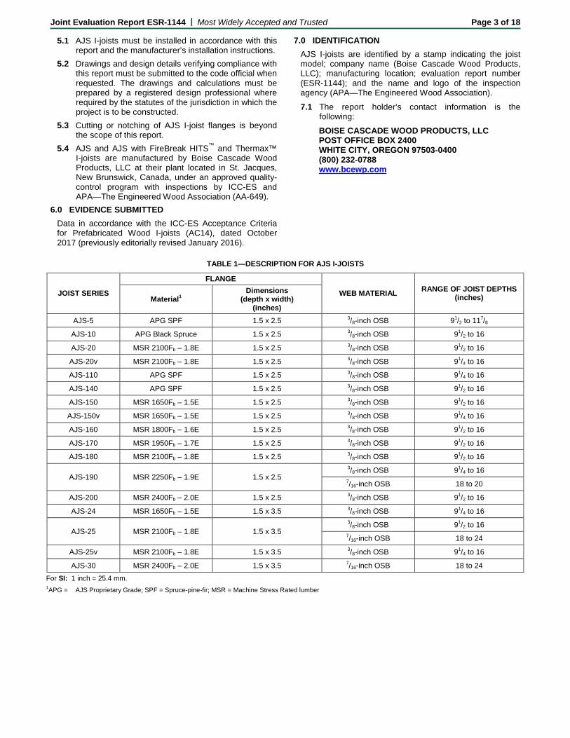
5.1 AJS I-joists must be installed in accordance with this report and the manufacturer’s installation instructions.
5.2 Drawings and design details verifying compliance with this report must be submitted to the code official when requested. The drawings and calculations must be prepared by a registered design professional where required by the statutes of the jurisdiction in which the project is to be constructed.
5.3 Cutting or notching of AJS I-joist flanges is beyond the scope of this report.
5.4 AJS and AJS with FireBreak HITS™ and Thermax™ I-joists are manufactured by Boise Cascade Wood Products, LLC at their plant located in St. Jacques, New Brunswick, Canada, under an approved quality-control program with inspections by ICC-ES and APA—The Engineered Wood Association (AA-649).
6.0 EVIDENCE SUBMITTED Data in accordance with the ICC-ES Acceptance Criteria for Prefabricated Wood I-joists (AC14), dated October 2017 (previously editorially revised January 2016).
7.0 IDENTIFICATION AJS I-joists are identified by a stamp indicating the joist model; company name (Boise Cascade Wood Products, LLC); manufacturing location; evaluation report number (ESR-1144); and the name and logo of the inspection agency (APA—The Engineered Wood Association). 7.1 The report holder’s contact information is the
following: BOISE CASCADE WOOD PRODUCTS, LLC POST OFFICE BOX 2400 WHITE CITY, OREGON 97503-0400 (800) 232-0788 www.bcewp.com
TABLE 1—DESCRIPTION FOR AJS I-JOISTS
JOIST SERIES
FLANGE
WEB MATERIAL RANGE OF JOIST DEPTHS (inches) Material1
Dimensions (depth x width)
(inches) AJS-5 APG SPF 1.5 x 2.5 3/8-inch OSB 91/2 to 117/8
AJS-10 APG Black Spruce 1.5 x 2.5 3/8-inch OSB 91/2 to 16
AJS-20 MSR 2100Fb – 1.8E 1.5 x 2.5 3/8-inch OSB 91/2 to 16
AJS-20v MSR 2100Fb – 1.8E 1.5 x 2.5 3/8-inch OSB 91/4 to 16
AJS-110 APG SPF 1.5 x 2.5 3/8-inch OSB 91/4 to 16
AJS-140 APG SPF 1.5 x 2.5 3/8-inch OSB 91/2 to 16
AJS-150 MSR 1650Fb – 1.5E 1.5 x 2.5 3/8-inch OSB 91/2 to 16
AJS-150v MSR 1650Fb – 1.5E 1.5 x 2.5 3/8-inch OSB 91/4 to 16
AJS-160 MSR 1800Fb – 1.6E 1.5 x 2.5 3/8-inch OSB 91/2 to 16
AJS-170 MSR 1950Fb – 1.7E 1.5 x 2.5 3/8-inch OSB 91/2 to 16
AJS-180 MSR 2100Fb – 1.8E 1.5 x 2.5 3/8-inch OSB 91/2 to 16
AJS-190 MSR 2250Fb – 1.9E 1.5 x 2.5 3/8-inch OSB 91/4 to 16 7/16-inch OSB 18 to 20
AJS-200 MSR 2400Fb – 2.0E 1.5 x 2.5 3/8-inch OSB 91/2 to 16
AJS-24 MSR 1650Fb – 1.5E 1.5 x 3.5 3/8-inch OSB 91/4 to 16
AJS-25 MSR 2100Fb – 1.8E 1.5 x 3.5 3/8-inch OSB 91/2 to 16 7/16-inch OSB 18 to 24
AJS-25v MSR 2100Fb – 1.8E 1.5 x 3.5 3/8-inch OSB 91/4 to 16
AJS-30 MSR 2400Fb – 2.0E 1.5 x 3.5 7/16-inch OSB 18 to 24 For SI: 1 inch = 25.4 mm. 1APG = AJS Proprietary Grade; SPF = Spruce-pine-fir; MSR = Machine Stress Rated lumber
Joint Evaluation Report ESR-1144 | Most Widely Accepted and Trusted Page 4 of 18
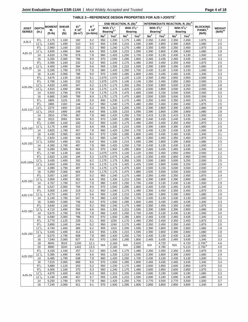
TABLE 2—REFERENCE DESIGN PROPERTIES FOR AJS I-JOISTS1
JOIST SERIES
DEPTH (in.)
MOMENT Mr
(ft-lb)
SHEAR Vr
(lb)
EI 2 X 10⁶
(lb-in2)
K 2 x 10⁶
(in-lb/in)
END REACTION, Rr (lb) 9 INTERMEDIATE REACTION, Rr (lb) 9 BLOCKING
PANEL6 (lb/ft)
WEIGHT (lb/ft)10
With 11/2" Bearing3,7
With 31/2" Bearing
With 31/2" Bearing3
With 51/4" Bearing
No4 Yes5 No4 Yes5 No4 Yes5 No4 Yes5
AJS-5 91/2 2,175 1,160 182 5.2 950 1,200 1,175 1,480 2,350 2,450 2,350 2,450 1,875 2.2 117/8 2,820 1,490 310 6.6 955 1,335 1,215 1,595 2,390 2,800 2,390 2,800 1,680 2.5
AJS-10
91/2 2,960 1,160 232 5.2 950 1,240 1,175 1,480 2,350 2,450 2,350 2,450 1,875 2.5 117/8 3,835 1,490 394 6.6 955 1,335 1,215 1,595 2,390 2,800 2,390 2,800 1,680 2.8 14 4,620 1,790 578 7.8 960 1,420 1,250 1,700 2,430 3,130 2,430 3,130 1,500 3.0 16 5,355 2,065 786 9.0 970 1,500 1,285 1,800 2,465 3,435 2,465 3,435 1,340 3.3
AJS-20
91/2 3,395 1,160 232 5.2 950 1,240 1,175 1,480 2,350 2,450 2,350 2,450 1,875 2.5 117/8 4,400 1,490 394 6.6 955 1,335 1,215 1,595 2,390 2,800 2,390 2,800 1,680 2.8 14 5,295 1,790 578 7.8 960 1,420 1,250 1,700 2,430 3,130 2,430 3,130 1,500 3.0 16 6,140 2,065 786 9.0 970 1,500 1,285 1,800 2,465 3,435 2,465 3,435 1,340 3.3
AJS-20v
91/4 3,675 1,130 218 5.1 1,075 1,075 1,120 1,120 2,350 2,450 2,850 2,950 2,000 2.5 91/2 3,795 1,160 232 5.2 1,075 1,075 1,145 1,145 2,350 2,450 2,850 2,950 2,000 2.5
111/4 4,620 1,400 347 6.2 1,175 1,175 1,355 1,355 2,500 2,800 3,000 3,250 2,000 2.8 117/8 4,915 1,490 394 6.6 1,175 1,175 1,425 1,425 2,500 2,800 3,000 3,250 2,000 2.8 14 5,920 1,790 579 7.8 1,175 1,175 1,475 1,665 2,500 3,150 3,000 3,500 2,000 3.0 16 6,865 2,065 789 8.9 1,175 1,175 1,475 1,885 2,500 3,500 3,000 3,500 2,000 3.3
AJS-110
91/4 1805 1125 135 5.0 950 1,230 1,170 1,480 2,350 2,450 2,350 2,450 1,875 2.5 91/2 1865 1160 144 5.2 950 1,240 1,175 1,480 2,350 2,450 2,350 2,450 1,875 2.5
111/4 2270 1400 218 6.2 955 1,310 1,205 1,595 2,390 2,800 2,390 2,800 1,680 2.8 117/8 2415 1490 248 6.6 955 1,335 1,215 1,595 2,390 2,800 2,390 2,800 1,680 2.8 14 2910 1790 367 7.8 960 1,420 1,250 1,700 2,415 3,130 2,415 3,130 1,500 3.0 16 3315 2065 504 9.0 970 1,500 1,285 1,800 2,440 3,435 2,440 3,435 1,340 3.3
AJS-140
91/2 2,450 1,160 182 5.2 950 1,240 1,175 1,480 2,350 2,450 2,350 2,450 1,875 2.2 117/8 3,175 1,490 310 6.6 955 1,335 1,215 1,595 2,390 2,800 2,390 2,800 1,680 2.5 14 3,825 1,790 457 7.8 960 1,420 1,250 1,700 2,430 3,130 2,430 3,130 1,500 2.8 16 4,435 2,065 623 9.0 970 1,500 1,285 1,800 2,465 3,435 2,465 3,435 1,340 3.1
AJS-150
91/2 2,820 1,160 194 5.2 950 1,240 1,175 1,480 2,350 2,450 2,350 2,450 1,875 2.2 117/8 3,650 1,490 331 6.6 955 1,335 1,215 1,595 2,390 2,800 2,390 2,800 1,680 2.5 14 4,390 1,790 487 7.8 960 1,420 1,250 1,700 2,430 3,130 2,430 3,130 1,500 2.7 16 5,090 2,065 664 9.0 970 1,500 1,285 1,800 2,465 3,435 2,465 3,435 1,340 3.0
AJS-150v
91/4 2,740 1,130 182 5.1 1,075 1,075 1,120 1,120 2,350 2,450 2,850 2,950 2,000 2.2 91/2 2,820 1,160 194 5.2 1,075 1,075 1,145 1,145 2,350 2,450 2,850 2,950 2,000 2.2
111/4 3,430 1,400 292 6.2 1,175 1,175 1,355 1,355 2,500 2,800 3,000 3,250 2,000 2.5 117/8 3,650 1,490 331 6.6 1,175 1,175 1,425 1,425 2,500 2,800 3,000 3,250 2,000 2.5 14 4,390 1,790 487 7.8 1,175 1,175 1,475 1,665 2,500 3,150 3,000 3,500 2,000 2.7 16 5,090 2,065 664 9.0 1,175 1,175 1,475 1,885 2,500 3,500 3,000 3,500 2,000 3.0
AJS-160
91/2 3,057 1,160 207 5.2 950 1,240 1,175 1,480 2,350 2,450 2,350 2,450 1,875 2.4 117/8 3,959 1,490 352 6.6 955 1,335 1,215 1,595 2,390 2,800 2,390 2,800 1,680 2.7 14 4,767 1,790 517 7.8 960 1,420 1,250 1,700 2,430 3,130 2,430 3,130 1,500 2.9 16 5,527 2,065 705 9.0 970 1,500 1,285 1,800 2,465 3,435 2,465 3,435 1,340 3.2
AJS-170
91/2 3,300 1,160 219 5.2 950 1,240 1,175 1,480 2,350 2,450 2,350 2,450 1,875 2.5 117/8 4,270 1,490 372 6.6 955 1,335 1,215 1,595 2,390 2,800 2,390 2,800 1,680 2.8 14 5,140 1,790 547 7.8 960 1,420 1,250 1,700 2,430 3,130 2,430 3,130 1,500 3.0 16 5,960 2,065 746 9.0 970 1,500 1,285 1,800 2,465 3,435 2,465 3,435 1,340 3.3
AJS-180
91/2 3,640 1,160 232 5.2 950 1,240 1,175 1,480 2,350 2,450 2,350 2,450 1,875 2.5 117/8 4,710 1,490 394 6.6 955 1,335 1,215 1,595 2,390 2,800 2,390 2,800 1,680 2.8 14 5,675 1,790 578 7.8 960 1,420 1,250 1,700 2,430 3,130 2,430 3,130 1,500 3.0 16 6,580 2,065 786 9.0 970 1,500 1,285 1,800 2,465 3,435 2,465 3,435 1,340 3.3
AJS-190
91/4 3,770 1,125 229 5.1 950 1230 1,170 1,480 2,350 2,450 2,350 2,450 1,875 2.5 91/2 3,895 1,160 244 5.2 950 1240 1,175 1,480 2,350 2,450 2,350 2,450 1,875 2.5
111/4 4,740 1,400 365 6.2 955 1310 1,205 1,595 2,390 2,800 2,390 2,800 1,680 2.8 117/8 5,045 1,490 414 6.6 955 1,335 1,215 1,595 2,390 2,800 2,390 2,800 1,680 2.8 14 6,070 1,790 608 7.8 960 1,420 1,250 1,700 2,430 3,130 2,430 3,130 1,500 3.0 16 7,040 2,065 827 9.0 970 1,500 1,285 1,800 2,465 3,435 2,465 3,435 1,340 3.3 18 8045 3010 1100 12.1 N/A 2,160 N/A 2,620 N/A 4,720 N/A 4,720 2,700 8 4.6 20 8990 3240 1402 13.5 2,160 2,980 4,780 5,110 2,700 8 4.9
AJS-200
91/2 4,155 1,160 257 5.2 950 1,240 1,175 1,480 2,350 2,450 2,350 2,450 1,875 2.6 117/8 5,385 1,490 435 6.6 955 1,335 1,215 1,595 2,390 2,800 2,390 2,800 1,680 2.9 14 6,485 1,790 638 7.8 960 1,420 1,250 1,700 2,430 3,130 2,430 3,130 1,500 3.1 16 7,515 2,065 868 9.0 970 1,500 1,285 1,800 2,465 3,435 2,465 3,435 1,340 3.4
AJS-24
91/4 3,880 1,125 253 5.2 950 1,230 1,170 1,480 2,600 2,850 2,600 2,850 1,875 3.0 91/2 4,005 1,160 270 5.3 950 1,240 1,175 1,480 2,600 2,850 2,600 2,850 1,875 3.1
111/4 4,875 1,400 403 6.3 955 1,310 1,205 1,595 2,690 3,190 2,690 3,190 1,680 3.3 117/8 5,190 1,490 457 6.7 955 1,335 1,215 1,595 2,690 3,190 2,690 3,190 1,680 3.4 14 6,250 1,790 670 7.9 960 1,420 1,250 1,700 2,770 3,500 2,770 3,500 1,500 3.7 16 7,245 2,065 911 9.1 970 1,500 1,285 1,800 2,850 3,800 2,850 3,800 1,340 3.9
Joint Evaluation Report ESR-1144 | Most Widely Accepted and Trusted Page 5 of 18
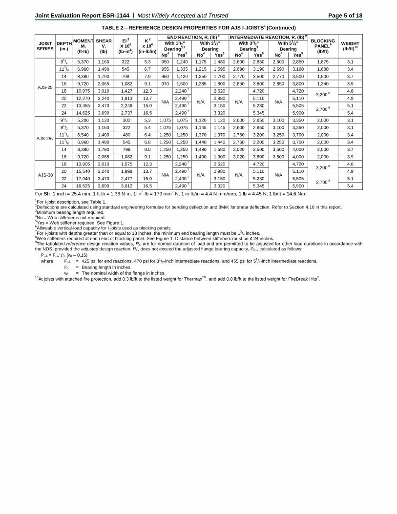
TABLE 2—REFERENCE DESIGN PROPERTIES FOR AJS I-JOISTS1 (Continued)
JOIST SERIES
DEPTH (in.)
MOMENT Mr
(ft-lb)
SHEAR Vr
(lb)
EI 2 X 10⁶
(lb-in2)
K 2 x 10⁶
(in-lb/in)
END REACTION, Rr (lb) 9 INTERMEDIATE REACTION, Rr (lb) 9 BLOCKING
PANEL6 (lb/ft)
WEIGHT (lb/ft)10
With 11/2" Bearing3,7
With 31/2" Bearing
With 31/2" Bearing3
With 51/4" Bearing
No4 Yes5 No4 Yes5 No4 Yes5 No4 Yes5
AJS-25
91/2 5,370 1,160 322 5.3 950 1,240 1,175 1,480 2,600 2,850 2,600 2,850 1,875 3.1 117/8 6,960 1,490 545 6.7 955 1,335 1,215 1,595 2,690 3,190 2,690 3,190 1,680 3.4 14 8,380 1,790 798 7.9 960 1,420 1,250 1,700 2,770 3,500 2,770 3,500 1,500 3.7 16 9,720 2,065 1,082 9.1 970 1,500 1,285 1,800 2,850 3,800 2,850 3,800 1,340 3.9 18 10,975 3,010 1,427 12.3
N/A
2,240 7
N/A
2,620
N/A
4,720
N/A
4,720 3,200 8
4.6 20 12,270 3,240 1,813 13.7 2,490 7 2,980 5,110 5,110 4.9 22 13,455 3,470 2,249 15.0 2,490 7 3,150 5,230 5,505
2,700 8 5.1
24 14,625 3,690 2,737 16.5 2,490 7 3,320 5,345 5,900 5.4
AJS-25v
91/4 5,200 1,130 302 5.3 1,075 1,075 1,120 1,120 2,600 2,850 3,100 3,350 2,000 3.1 91/2 5,370 1,160 322 5.4 1,075 1,075 1,145 1,145 2,600 2,850 3,100 3,350 2,000 3.1
111/4 6,540 1,400 480 6.4 1,250 1,250 1,370 1,370 2,760 3,200 3,250 3,700 2,000 3.4 117/8 6,960 1,490 545 6.8 1,250 1,250 1,440 1,440 2,760 3,200 3,250 3,700 2,000 3.4 14 8,380 1,790 798 8.0 1,250 1,250 1,490 1,680 3,020 3,500 3,500 4,000 2,000 3.7 16 9,720 2,065 1,082 9.1 1,250 1,250 1,490 1,900 3,020 3,800 3,500 4,000 2,000 3.9
AJS-30
18 13,905 3,010 1,575 12.3
N/A
2,240 7
N/A
2,620
N/A
4,720
N/A
4,720 3,200 8
4.6 20 15,540 3,240 1,998 13.7 2,490 7 2,980 5,110 5,110 4.9 22 17,040 3,470 2,477 15.0 2,490 7 3,150 5,230 5,505
2,700 8 5.1
24 18,525 3,690 3,012 16.5 2,490 7 3,320 5,345 5,900 5.4
For SI: 1 inch = 25.4 mm; 1 ft-lb = 1.36 N-m; 1 in2-lb = 179 mm2-N, 1 in-lb/in = 4.4 N-mm/mm; 1 lb = 4.45 N; 1 lb/ft = 14.6 N/m. 1For I-joist description, see Table 1. 2Deflections are calculated using standard engineering formulae for bending deflection and 8M/K for shear deflection. Refer to Section 4.10 in this report. 3Minimum bearing length required. 4No = Web stiffener is not required. 5Yes = Web stiffener required. See Figure 1. 6Allowable vertical-load capacity for I-joists used as blocking panels. 7For I-joists with depths greater than or equal to 18 inches, the minimum end bearing length must be 13/4 inches. 8Web stiffeners required at each end of blocking panel. See Figure 1. Distance between stiffeners must be ≤ 24 inches. 9The tabulated reference design reaction values, Rr, are for normal duration of load and are permitted to be adjusted for other load durations in accordance with the NDS, provided the adjusted design reaction, Rr', does not exceed the adjusted flange bearing capacity, Pc┴, calculated as follows: Pc┴ = Fc┴' Ρb (wf – 0.15)
where: Fc┴' = 425 psi for end reactions, 470 psi for 31/2-inch intermediate reactions, and 455 psi for 51/4-inch intermediate reactions. Ρb = Bearing length in inches. wf = The nominal width of the flange in inches. 10At joists with attached fire protection, add 0.3 lb/ft to the listed weight for ThermaxTM, and add 0.8 lb/ft to the listed weight for FireBreak Hits®.
Joint Evaluation Report ESR-1144 | Most Widely Accepted and Trusted Page 6 of 18
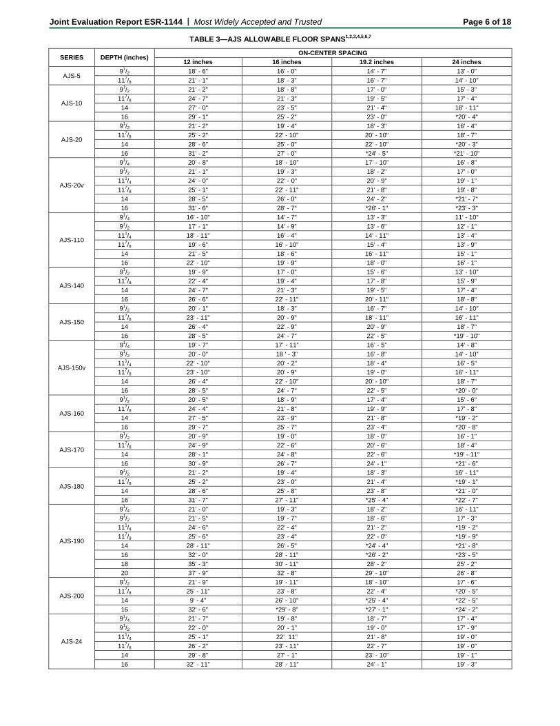
TABLE 3—AJS ALLOWABLE FLOOR SPANS1,2,3,4,5,6,7
SERIES DEPTH (inches) ON-CENTER SPACING 12 inches 16 inches 19.2 inches 24 inches
AJS-5 91/2 18' - 6" 16' - 0" 14' - 7" 13' - 0" 117/8 21' - 1" 18' - 3" 16' - 7" 14' - 10"
AJS-10
91/2 21' - 2" 18' - 8" 17' - 0" 15' - 3" 117/8 24' - 7" 21' - 3" 19' - 5" 17' - 4" 14 27' - 0" 23' - 5" 21' - 4" 18' - 11" 16 29' - 1" 25' - 2" 23' - 0" *20' - 4"
AJS-20
91/2 21' - 2" 19' - 4" 18' - 3" 16' - 4" 117/8 25' - 2" 22' - 10" 20' - 10" 18' - 7" 14 28' - 6" 25' - 0" 22' - 10" *20' - 3" 16 31' - 2" 27' - 0" *24' - 5" *21' - 10"
AJS-20v
91/4 20’ - 8” 18’ - 10” 17’ - 10” 16’ - 8” 91/2 21' - 1" 19' - 3" 18' - 2" 17' - 0" 111/4 24’ - 0” 22’ - 0” 20’ - 9” 19’ - 1” 117/8 25' - 1" 22' - 11" 21' - 8" 19' - 8" 14 28' - 5" 26' - 0" 24' - 2" *21' - 7" 16 31' - 6" 28' - 7" *26' - 1" *23' - 3"
AJS-110
91/4 16' - 10" 14' - 7" 13' - 3" 11' - 10" 91/2 17' - 1" 14' - 9" 13' - 6" 12' - 1" 111/4 18' - 11" 16' - 4" 14' - 11" 13' - 4" 117/8 19' - 6" 16' - 10" 15' - 4" 13' - 9" 14 21' - 5" 18' - 6" 16' - 11" 15' - 1" 16 22' - 10" 19' - 9" 18' - 0" 16' - 1"
AJS-140
91/2 19' - 9" 17' - 0" 15' - 6" 13' - 10" 117/8 22' - 4" 19' - 4" 17' - 8" 15' - 9" 14 24' - 7" 21' - 3" 19' - 5" 17' - 4" 16 26' - 6" 22' - 11" 20' - 11" 18' - 8"
AJS-150
91/2 20' - 1" 18' - 3" 16' - 7" 14' - 10" 117/8 23' - 11" 20' - 9" 18' - 11" 16' - 11" 14 26' - 4" 22' - 9" 20' - 9" 18' - 7" 16 28' - 5" 24' - 7" 22' - 5" *19' - 10"
AJS-150v
91/4 19’ - 7” 17’ - 11” 16’ - 5” 14’ - 8” 91/2 20' - 0" 18 ' - 3" 16' - 8" 14' - 10" 111/4 22’ - 10” 20’ - 2” 18’ - 4” 16’ - 5” 117/8 23' - 10" 20' - 9" 19' - 0" 16' - 11" 14 26' - 4" 22' - 10" 20' - 10" 18' - 7" 16 28' - 5" 24' - 7" 22' - 5" *20' - 0"
AJS-160
91/2 20' - 5" 18' - 9" 17' - 4" 15' - 6" 117/8 24' - 4" 21' - 8" 19' - 9" 17' - 8" 14 27' - 5" 23' - 9" 21' - 8" *19' - 2" 16 29' - 7" 25' - 7" 23' - 4" *20' - 8"
AJS-170
91/2 20' - 9" 19' - 0" 18' - 0" 16' - 1" 117/8 24' - 9" 22' - 6" 20' - 6" 18' - 4" 14 28' - 1" 24' - 8" 22' - 6" *19' - 11" 16 30' - 9" 26' - 7" 24' - 1" *21' - 6"
AJS-180
91/2 21' - 2" 19' - 4" 18' - 3" 16' - 11" 117/8 25' - 2" 23' - 0" 21' - 4" *19' - 1" 14 28' - 6" 25' - 8" 23' - 8" *21' - 0" 16 31' - 7" 27' - 11" *25' - 4" *22' - 7"
AJS-190
91/4 21' - 0" 19' - 3" 18' - 2" 16' - 11" 91/2 21' - 5" 19' - 7" 18' - 6" 17' - 3" 111/4 24' - 6" 22' - 4" 21' - 2" *19' - 2" 117/8 25' - 6" 23' - 4" 22' - 0" *19' - 9" 14 28' - 11" 26' - 5" *24' - 4" *21' - 8" 16 32' - 0" 28' - 11" *26' - 2" *23' - 5" 18 35' - 3" 30' - 11" 28' - 2" 25' - 2" 20 37' - 9" 32' - 8" 29' - 10" 26' - 8"
AJS-200
91/2 21' - 9" 19' - 11" 18' - 10" 17' - 6" 117/8 25' - 11" 23' - 8" 22' - 4" *20' - 5" 14 9' - 4" 26' - 10" *25' - 4" *22' - 5" 16 32' - 6" *29' - 8" *27' - 1" *24' - 2"
AJS-24
91/4 21’ - 7” 19’ - 8” 18’ - 7” 17’ - 4” 91/2 22’ - 0” 20’ - 1” 19’ - 0” 17’ - 9” 111/4 25’ - 1” 22’ 11” 21’ - 8” 19’ - 0” 117/8 26’ - 2” 23’ - 11” 22’ - 7” 19’ - 0” 14 29’ - 8” 27’ - 1” 23’ - 10” 19’ - 1” 16 32’ - 11” 28’ - 11” 24’ - 1” 19’ - 3”
Joint Evaluation Report ESR-1144 | Most Widely Accepted and Trusted Page 7 of 18
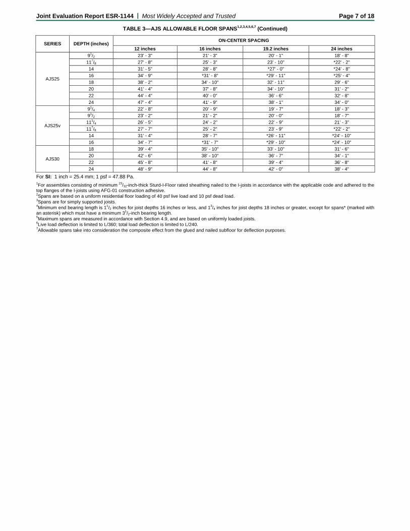
TABLE 3—AJS ALLOWABLE FLOOR SPANS1,2,3,4,5,6,7 (Continued)
SERIES DEPTH (inches) ON-CENTER SPACING
12 inches 16 inches 19.2 inches 24 inches
AJS25
91/2 23' - 3" 21' - 3" 20' - 1" 18' - 8" 117/8 27' - 8" 25' - 3" 23' - 10" *22' - 2" 14 31' - 5" 28' - 8" *27' - 0" *24' - 8" 16 34' - 9" *31' - 8" *29' - 11" *25' - 4" 18 38' - 2" 34' - 10" 32' - 11" 29' - 6" 20 41' - 4" 37' - 8" 34' - 10" 31' - 2" 22 44' - 4" 40' - 0" 36' - 6" 32' - 8" 24 47' - 4" 41' - 9" 38' - 1" 34' - 0"
AJS25v
91/4 22’ - 8” 20’ - 9” 19’ - 7” 18’ - 3” 91/2 23' - 2" 21' - 2" 20' - 0" 18' - 7" 111/4 26’ - 5” 24’ - 2” 22’ - 9” 21’ - 3” 117/8 27' - 7" 25' - 2" 23' - 9" *22' - 2" 14 31' - 4" 28' - 7" *26' - 11" *24' - 10" 16 34' - 7" *31' - 7" *29' - 10" *24' - 10"
AJS30
18 39' - 4" 35' - 10" 33' - 10" 31' - 6" 20 42' - 6" 38' - 10" 36' - 7" 34' - 1" 22 45' - 8" 41' - 8" 39' - 4" 36' - 8" 24 48' - 9" 44' - 8" 42' - 0" 38' - 4"
For SI: 1 inch = 25.4 mm; 1 psf = 47.88 Pa. 1For assemblies consisting of minimum 23/32-inch-thick Sturd-I-Floor rated sheathing nailed to the I-joists in accordance with the applicable code and adhered to the top flanges of the I-joists using AFG-01 construction adhesive. 2Spans are based on a uniform residential floor loading of 40 psf live load and 10 psf dead load. 3Spans are for simply supported joists. 4Minimum end bearing length is 11/2 inches for joist depths 16 inches or less, and 13/4 inches for joist depths 18 inches or greater, except for spans* (marked with an asterisk) which must have a minimum 31/2-inch bearing length. 5Maximum spans are measured in accordance with Section 4.9, and are based on uniformly loaded joists. 6Live load deflection is limited to L/360; total load deflection is limited to L/240. 7Allowable spans take into consideration the composite effect from the glued and nailed subfloor for deflection purposes.
Joint Evaluation Report ESR-1144 | Most Widely Accepted and Trusted Page 8 of 18
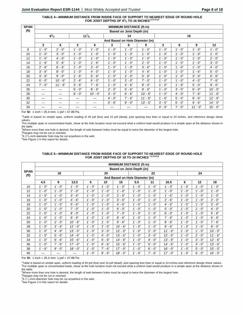
TABLE 4—MINIMUM DISTANCE FROM INSIDE FACE OF SUPPORT TO NEAREST EDGE OF ROUND HOLE FOR JOIST DEPTHS OF 91/2 TO 16 INCHES1,2,3,4,5,6
SPAN (ft)
MINIMUM DISTANCE (ft-in) Based on Joist Depth (in)
91/2 117/8 14 16 And Based on Hole Diameter (in)
3 6 3 6 3 6 9 3 6 9 12 8 1' - 0" 2' - 0" 1' - 0" 1' - 0" 1' - 0" 1' - 0" 1' - 0" 1' - 0" 1' - 0" 1' - 0" 1' - 0"
10 1' - 0" 3' - 0" 1' - 0" 1' - 0" 1' - 0" 1' - 0" 1' - 0" 1' - 0" 1' - 0" 1' - 0" 1' - 0" 12 1' - 0" 4' - 0" 1' - 0" 1' - 0" 1' - 0" 1' - 0" 1' - 0" 1' - 0" 1' - 0" 1' - 0" 2' - 0" 14 1' - 6" 5' - 6" 1' - 0" 1' - 6" 1' - 0" 1' - 0" 2' - 0" 1' - 0" 1' - 0" 1' - 0" 3' - 0" 16 2' - 6" 6' - 6" 1' - 0" 3' - 0" 1' - 0" 1' - 0" 3' - 6" 1' - 0" 1' - 0" 1' - 0" 4' - 0" 18 3' - 6" 8' - 0" 1' - 0" 4' - 0" 1' - 0" 1' - 0" 4' - 6" 1' - 0" 1' - 0" 1' - 6" 5' - 0" 20 4' - 6" 9' - 0" 1' - 6" 5' - 6" 1' - 0" 2' - 0" 5' - 6" 1' - 0" 1' - 0" 3' - 0" 6' - 6" 22 6' - 0" 10' - 6" 2' - 6" 6' - 0" 1' - 0" 3' - 0" 7' - 0" 1' - 0" 1' - 0" 4' - 0" 7' - 6" 24 7' - 0" 11' - 6" 3' - 6" 7' - 6" 1' - 0" 4' - 6" 8' - 0" 1' - 0" 1' - 6" 5' - 0" 9' - 0" 26 — — 5' - 0" 8' - 6" 2' - 0" 5' - 6" 9' - 0" 1' - 0" 3' - 0" 6' - 0" 10' - 0" 28 — — 6' - 0" 10' - 0" 3' - 0" 6' - 6" 10' - 6" 1' - 0" 4' - 0" 7' - 6" 11' - 6" 30 — — — — 4' - 0" 7' - 6" 11' - 6" 1' - 6" 5' - 0" 8' - 6" 12' - 6" 32 — — — — 5' - 6" 9' - 0" 13' - 0" 3' - 0" 6' - 0" 9' - 6" 14' - 0" 34 — — — — — — — 4' - 0" 7' - 0" 11' - 0" 15' - 0"
For SI: 1 inch = 25.4 mm; 1 psf = 47.88 Pa. 1Table is based on simple span, uniform loading of 40 psf (live) and 15 psf (dead), joist spacing less than or equal to 24 inches, and reference design shear values. 2For multiple span or concentrated loads, shear at the hole location must not exceed what a uniform load would produce in a simple span at the distance shown in the table. 3Where more than one hole is desired, the length of web between holes must be equal to twice the diameter of the largest hole. 4Flanges may not be cut or notched. 5A 11/2-inch-diameter hole may be cut anywhere in the web. 6See Figure 2 in this report for details.
TABLE 5—MINIMUM DISTANCE FROM INSIDE FACE OF SUPPORT TO NEAREST EDGE OF ROUND HOLE FOR JOIST DEPTHS OF 18 TO 24 INCHES 1,2,3,4,5,6
For SI: 1 inch = 25.4 mm; 1 psf = 47.88 Pa. 1Table is based on simple span, uniform loading of 40 psf (live) and 15 psf (dead), joist spacing less than or equal to 24 inches and reference design shear values. 2For multiple span or concentrated loads, shear at the hole location must not exceed what a uniform load would produce in a simple span at the distance shown in the table. 3Where more than one hole is desired, the length of web between holes must be equal to twice the diameter of the largest hole. 4Flanges may not be cut or notched. 5A 11
/2-inch-diameter hole may be cut anywhere in the web. 6See Figure 2 in this report for details.
SPAN (ft)
MINIMUM DISTANCE (ft-in) Based on Joist Depth (in)
18 20 22 24 And Based on Hole Diameter (in)
4.5 9 13.5 5 10 15 5.5 11 16.5 6 12 18 10 1' - 0" 1' - 0" 1' - 0" 1' - 0" 1' - 0" 1' - 0" 1' - 0" 1' - 0" 1' - 0" 1' - 0" 1' - 0" 1' - 0" 12 1' - 0" 1' - 0" 2' - 0" 1' - 0" 1' - 0" 1' - 6" 1' - 0" 1' - 0" 1' - 0" 1' - 0" 1' - 0" 1' - 0" 14 1' - 0" 1' - 0" 3' - 6" 1' - 0" 1' - 0" 2' - 6" 1' - 0" 1' - 0" 1' - 6" 1' - 0" 1' - 0" 1' - 0" 16 1' - 0" 1' - 0" 4' - 6" 1' - 0" 1' - 0" 3' - 6" 1' - 0" 1' - 0" 2' - 6" 1' - 0" 1' - 0" 2' - 0" 18 1' - 0" 1' - 0" 5' - 6" 1' - 0" 1' - 0" 4' - 6" 1' - 0" 1' - 0" 4' - 0" 1' - 0" 1' - 0" 3' - 0" 20 1' - 0" 1' - 0" 7' - 0" 1' - 0" 1' - 0" 6' - 0" 1' - 0" 1' - 0" 5' - 0" 1' - 0" 1' - 0" 4' - 0" 22 1' - 0" 1' - 0" 8' - 0" 1' - 0" 1' - 0" 7' - 0" 1' - 0" 1' - 0" 6' - 0" 1' - 0" 1' - 0" 5' - 6" 24 1' - 0" 1' - 0" 9' - 6" 1' - 0" 1' - 0" 8' - 6" 1' - 0" 1' - 0" 7' - 6" 1' - 0" 1' - 0" 6' - 6" 26 1' - 0" 2' - 0" 10' - 6" 1' - 0" 1' - 0" 9' - 6" 1' - 0" 1' - 0" 8' - 6" 1' - 0" 1' - 0" 7' - 6" 28 1' - 0" 3' - 6" 12' - 0" 1' - 0" 2' - 0" 10' - 6" 1' - 0" 1' - 0" 9' - 6" 1' - 0" 1' - 0" 9' - 0" 30 1' - 0" 4' - 6" 13' - 0" 1' - 0" 3' - 0" 12' - 0" 1' - 0" 2' - 0" 11' - 0" 1' - 0" 1' - 0" 10' - 0" 32 1' - 0" 5' - 6" 14' - 6" 1' - 0" 4' - 0" 13' - 0" 1' - 0" 3' - 0" 12' - 0" 1' - 0" 2' - 0" 11' - 6" 34 1' - 0" 6' - 6" 15' - 6" 1' - 0" 5' - 6" 14' - 6" 1' - 0" 4' - 0" 13' - 6" 1' - 0" 3' - 0" 12' - 6" 36 1' - 0" 7' - 6" 17' - 0" 1' - 0" 6' - 6" 15' - 6" 1' - 0" 5' - 0" 14' - 6" 1' - 0" 4' - 0" 13' - 6" 38 1' - 6" 9' - 0" 18' - 0" 1' - 0" 7' - 6" 17' - 0" 1' - 0" 6' - 0" 16' - 0" 1' - 0" 5' - 0" 15' - 0" 40 — — — 1' - 0" 8' - 6" 18' - 0" 1' - 0" 7' - 6" 17' - 0" 1' - 0" 6' - 0" 16' - 0"
Joint Evaluation Report ESR-1144 | Most Widely Accepted and Trusted Page 9 of 18
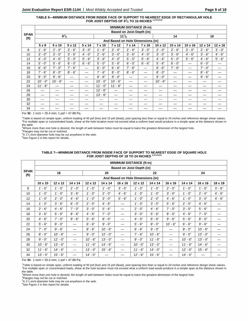
TABLE 6—MINIMUM DISTANCE FROM INSIDE FACE OF SUPPORT TO NEAREST EDGE OF RECTANGULAR HOLE FOR JOIST DEPTHS OF 91/2 TO 16 INCHES 1,2,3,4,5,6
SPAN (ft)
MINIMUM DISTANCE (ft-in) Based on Joist Depth (in)
91/2 117/8 14 16 And Based on Hole Dimensions (in)
5 x 8 5 x 10 5 x 12 5 x 14 7 x 10 7 x 12 7 x 14 7 x 16 10 x 12 10 x 14 10 x 16 12 x 14 12 x 16 8 1' - 6" 2' - 0" 2' - 6" 3' - 0" 1' - 6" 2' - 0" 2' - 6" 3' - 0" 2' - 0" 2' - 6" 3' - 0" 2' - 6" 3' - 0"
10 3' - 0" 3' - 0" 3' - 6" 4' - 0" 2' - 6" 3' - 0" 3' - 6" 4' - 0" 3' - 0" 3' - 6" 4' - 6" 3' - 6" 4' - 6" 12 4' - 0" 4' - 6" 5' - 0" 5' - 6" 3' - 6" 4' - 0" 5' - 0" 5' - 6" 4' - 6" 5' - 0" 5' - 6" 4' - 6" 5' - 6" 14 5' - 0" 5' - 6" 6' - 0" 6' - 6" 5' - 0" 5' - 6" 6' - 0" 6' - 6" 5' - 6" 6' - 0" — 6' - 0" — 16 6' - 6" 7' - 0" 7' - 6" — 6' - 0" 6' - 6" 7' - 6" — 6' - 6" 7' - 6" — 7' - 0" — 18 7' - 6" 8' - 0" 8' - 6" — 7' - 6" 8' - 0" 8' - 6" — 8' - 0" — — 8' - 6" — 20 9' - 0" 9' - 6" — — 8' - 6" 9' - 0" — — 9' - 0" — — 9' - 6" — 22 10' - 0" 10' - 6" — — 10' - 0" 10' - 6" — — 10' - 6" — — — — 24 11' - 6" — — — 11' - 0" 11' - 6" — — — — — — — 26 — — — — 12' - 6" — — — — — — — — 28 — — — — 13' - 6" — — — — — — — — 30 — — — — — — — — — — — — — 32 — — — — — — — — — — — — — 34 — — — — — — — — — — — — —
For SI: 1 inch = 25.4 mm; 1 psf = 47.88 Pa. 1Table is based on simple span, uniform loading of 40 psf (live) and 15 psf (dead), joist spacing less than or equal to 24 inches and reference design shear values. 2For multiple span or concentrated loads, shear at the hole location must not exceed what a uniform load would produce in a simple span at the distance shown in the table. 3Where more than one hole is desired, the length of web between holes must be equal to twice the greatest dimension of the largest hole. 4Flanges may not be cut or notched. 5A 11/2-inch-diameter hole may be cut anywhere in the web. 6See Figure 2 in this report for details.
TABLE 7—MINIMUM DISTANCE FROM INSIDE FACE OF SUPPORT TO NEAREST EDGE OF SQUARE HOLE FOR JOIST DEPTHS OF 18 TO 24 INCHES 1,2,3,4,5,6
SPAN (ft)
MINIMUM DISTANCE (ft-in) Based on Joist Depth (in)
18 20 22 24 And Based on Hole Dimensions (in)
10 x 10 12 x 12 14 x 14 12 x 12 14 x 14 16 x 16 12 x 12 14 x 14 16 x 16 14 x 14 16 x 16 18 x 18 8 1' - 0" 1' - 0" 2' - 0" 1' - 0" 1' - 0" 3' - 0" 1' - 0" 1' - 0" 2' - 0" 1' - 0" 1' - 0" 3' - 6"
10 1' - 0" 1' - 0" 3' - 6" 1' - 0" 2' - 0" 4' - 6" 1' - 0" 1' - 0" 3' - 0" 1' - 0" 2' - 0" 4' - 6" 12 1' - 0" 2' - 0" 4' - 6" 1' - 0" 3' - 0" 5' - 6" 1' - 0" 2' - 0" 4' - 6" 1' - 0" 3' - 0" 4' - 6" 14 1' - 0" 3' - 6" 6' - 0" 2' - 0" 4' - 6" — 1' - 0" 3' - 0" 5' - 6" 2' - 0" 4' - 6" — 16 2' - 6" 4' - 6" 7' - 0" 3' - 0" 5' - 6" — 2' - 0" 4' - 6" 7' - 0" 3' - 0" 5' - 6" — 18 3' - 6" 5' - 6" 8' - 6" 4' - 6" 7' - 0" — 3' - 0" 5' - 6" 8' - 0" 4' - 6" 7' - 0" — 20 4' - 6" 7' - 0" 9' - 6" 5' - 6" 8' - 0" — 4' - 0" 6' - 6" 9' - 6" 5' - 6" 8' - 0" — 22 5' - 6" 8' - 0" — 6' - 6" 9' - 0" — 5' - 6" 8' - 0" 10' - 6" 6' - 6" 9' - 6" — 24 7' - 0" 9' - 6" — 8' - 6" 10' - 6" — 6' - 6" 9' - 0" — 8' - 0" 10' - 6" — 26 8' - 0" 10' - 6" — 9' - 0" 12' - 0" — 7' - 6" 10' - 6" — 9' - 0" 12' - 0" — 28 9' - 0" 12' - 0" — 10' - 6" 13' - 0" — 9' - 0" 11' - 6" — 10' - 6" 13' - 0" — 30 10' - 6" 13' - 0" — 11' - 6" 14' - 6" — 10' - 0" 13' - 0" — 11' - 6" 14' - 6" — 32 11' - 6" 14' - 6" — 13' - 0" 15' - 6" — 11' - 6" 14' - 0" — 12' - 6" 15' - 6" — 34 13' - 0" 15' - 6" — 14' - 0" — — 12' - 6" 15' - 6" — 14' - 0" — —
For SI: 1 inch = 25.4 mm; 1 psf = 47.88 Pa. 1Table is based on simple span, uniform loading of 40 psf (live) and 15 psf (dead), joist spacing less than or equal to 24 inches and reference design shear values. 2For multiple span or concentrated loads, shear at the hole location must not exceed what a uniform load would produce in a simple span at the distance shown in the table. 3Where more than one hole is desired, the length of web between holes must be equal to twice the greatest dimension of the largest hole. 4Flanges may not be cut or notched. 5A 11/2-inch-diameter hole may be cut anywhere in the web. 6See Figure 2 in this report for details.
Joint Evaluation Report ESR-1144 | Most Widely Accepted and Trusted Page 10 of 18
2" min.4" max.
Tight Fit
Tight Fit
Small Gap
Web stiffener required when load to joist exceeds 1000 lb
Web stiffener when required for end bearing (see Table 2)
Web stiffener when required for intermediate
bearing (see Table 2) Structural Panel Web Stiffener 1" thick x 2 5/16" wide for 1.5" x 2.5" flange2x4 lumber (vertical) for 1.5" x 3.5" flange
Nails2" min.4" max.
Small Gap1/8" min.1/4” max.
Joist Depth Minimum Required Fasteners
9 1/4" - 11 7/8" 3-10d (3" x 0.125")14" - 24" 5-10d (3" x 0.125")
Web Stiffener Fastener Schedule
FIGURE 1—WEB-STIFFENER INSTALLATION REQUIREMENTS
MinimumDistance
Minimum Distance
D1 2 x D2 D2 1 ½” hole max
L2 L12 x L2L
MinimumDistance
Minimum Distance
Minimum Distance
FIGURE 2—HOLE-IN-WEB REQUIREMENTS
Joint Evaluation Report ESR-1144 | Most Widely Accepted and Trusted Page 11 of 18
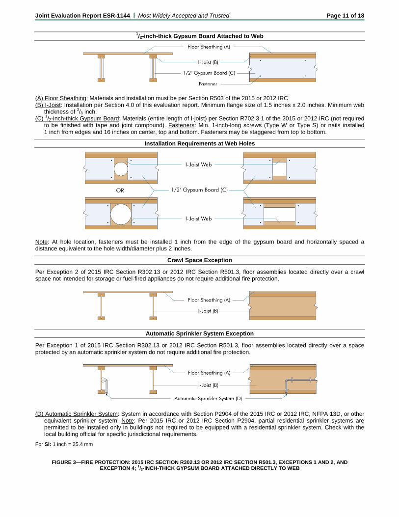
1/2-inch-thick Gypsum Board Attached to Web
(A) Floor Sheathing: Materials and installation must be per Section R503 of the 2015 or 2012 IRC (B) I-Joist: Installation per Section 4.0 of this evaluation report. Minimum flange size of 1.5 inches x 2.0 inches. Minimum web
thickness of 3/8 inch. (C) 1/2-inch-thick Gypsum Board: Materials (entire length of I-joist) per Section R702.3.1 of the 2015 or 2012 IRC (not required
to be finished with tape and joint compound). Fasteners: Min. 1-inch-long screws (Type W or Type S) or nails installed 1 inch from edges and 16 inches on center, top and bottom. Fasteners may be staggered from top to bottom.
Installation Requirements at Web Holes
Note: At hole location, fasteners must be installed 1 inch from the edge of the gypsum board and horizontally spaced a distance equivalent to the hole width/diameter plus 2 inches.
Crawl Space Exception
Per Exception 2 of 2015 IRC Section R302.13 or 2012 IRC Section R501.3, floor assemblies located directly over a crawl space not intended for storage or fuel-fired appliances do not require additional fire protection.
Automatic Sprinkler System Exception
Per Exception 1 of 2015 IRC Section R302.13 or 2012 IRC Section R501.3, floor assemblies located directly over a space protected by an automatic sprinkler system do not require additional fire protection.
(D) Automatic Sprinkler System: System in accordance with Section P2904 of the 2015 IRC or 2012 IRC, NFPA 13D, or other
equivalent sprinkler system. Note: Per 2015 IRC or 2012 IRC Section P2904, partial residential sprinkler systems are permitted to be installed only in buildings not required to be equipped with a residential sprinkler system. Check with the local building official for specific jurisdictional requirements.
For SI: 1 inch = 25.4 mm
FIGURE 3—FIRE PROTECTION: 2015 IRC SECTION R302.13 OR 2012 IRC SECTION R501.3, EXCEPTIONS 1 AND 2, AND EXCEPTION 4; 1/2-INCH-THICK GYPSUM BOARD ATTACHED DIRECTLY TO WEB
Joint Evaluation Report ESR-1144 | Most Widely Accepted and Trusted Page 12 of 18
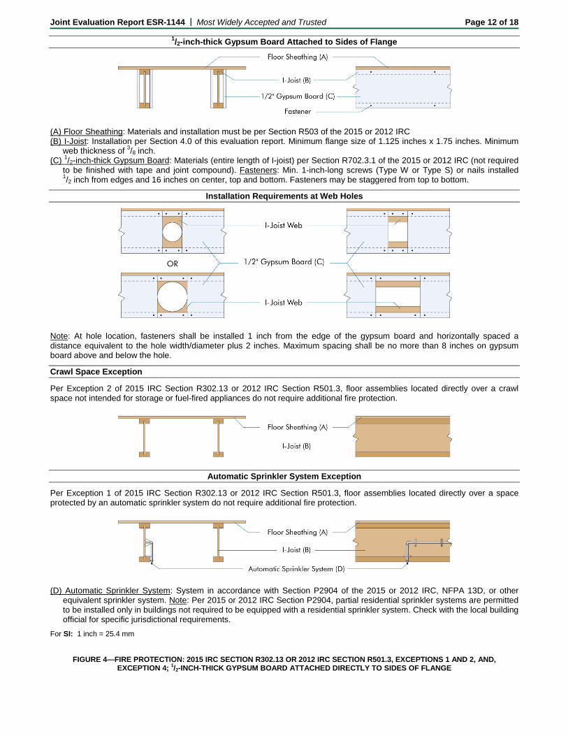
1/2-inch-thick Gypsum Board Attached to Sides of Flange
(A) Floor Sheathing: Materials and installation must be per Section R503 of the 2015 or 2012 IRC (B) I-Joist: Installation per Section 4.0 of this evaluation report. Minimum flange size of 1.125 inches x 1.75 inches. Minimum
web thickness of 3/8 inch. (C) 1/2-inch-thick Gypsum Board: Materials (entire length of I-joist) per Section R702.3.1 of the 2015 or 2012 IRC (not required
to be finished with tape and joint compound). Fasteners: Min. 1-inch-long screws (Type W or Type S) or nails installed 1/2 inch from edges and 16 inches on center, top and bottom. Fasteners may be staggered from top to bottom.
Installation Requirements at Web Holes
Note: At hole location, fasteners shall be installed 1 inch from the edge of the gypsum board and horizontally spaced a distance equivalent to the hole width/diameter plus 2 inches. Maximum spacing shall be no more than 8 inches on gypsum board above and below the hole.
Crawl Space Exception
Per Exception 2 of 2015 IRC Section R302.13 or 2012 IRC Section R501.3, floor assemblies located directly over a crawl space not intended for storage or fuel-fired appliances do not require additional fire protection.
Automatic Sprinkler System Exception
Per Exception 1 of 2015 IRC Section R302.13 or 2012 IRC Section R501.3, floor assemblies located directly over a space protected by an automatic sprinkler system do not require additional fire protection.
(D) Automatic Sprinkler System: System in accordance with Section P2904 of the 2015 or 2012 IRC, NFPA 13D, or other
equivalent sprinkler system. Note: Per 2015 or 2012 IRC Section P2904, partial residential sprinkler systems are permitted to be installed only in buildings not required to be equipped with a residential sprinkler system. Check with the local building official for specific jurisdictional requirements.
For SI: 1 inch = 25.4 mm
FIGURE 4—FIRE PROTECTION: 2015 IRC SECTION R302.13 OR 2012 IRC SECTION R501.3, EXCEPTIONS 1 AND 2, AND,
EXCEPTION 4; 1/2-INCH-THICK GYPSUM BOARD ATTACHED DIRECTLY TO SIDES OF FLANGE
Joint Evaluation Report ESR-1144 | Most Widely Accepted and Trusted Page 13 of 18
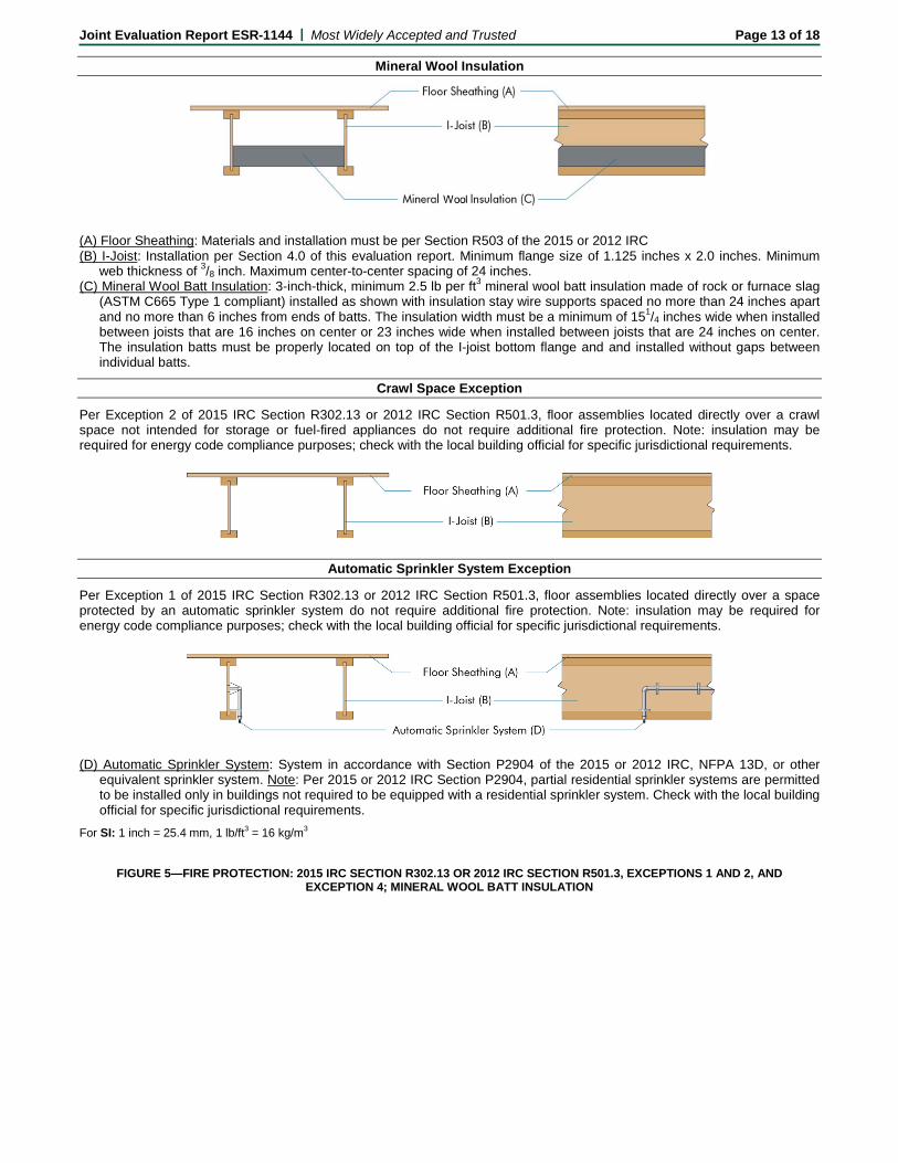
Mineral Wool Insulation
(A) Floor Sheathing: Materials and installation must be per Section R503 of the 2015 or 2012 IRC (B) I-Joist: Installation per Section 4.0 of this evaluation report. Minimum flange size of 1.125 inches x 2.0 inches. Minimum
web thickness of 3/8 inch. Maximum center-to-center spacing of 24 inches. (C) Mineral Wool Batt Insulation: 3-inch-thick, minimum 2.5 lb per ft3 mineral wool batt insulation made of rock or furnace slag
(ASTM C665 Type 1 compliant) installed as shown with insulation stay wire supports spaced no more than 24 inches apart and no more than 6 inches from ends of batts. The insulation width must be a minimum of 151/4 inches wide when installed between joists that are 16 inches on center or 23 inches wide when installed between joists that are 24 inches on center. The insulation batts must be properly located on top of the I-joist bottom flange and and installed without gaps between individual batts.
Crawl Space Exception
Per Exception 2 of 2015 IRC Section R302.13 or 2012 IRC Section R501.3, floor assemblies located directly over a crawl space not intended for storage or fuel-fired appliances do not require additional fire protection. Note: insulation may be required for energy code compliance purposes; check with the local building official for specific jurisdictional requirements.
Automatic Sprinkler System Exception
Per Exception 1 of 2015 IRC Section R302.13 or 2012 IRC Section R501.3, floor assemblies located directly over a space protected by an automatic sprinkler system do not require additional fire protection. Note: insulation may be required for energy code compliance purposes; check with the local building official for specific jurisdictional requirements.
(D) Automatic Sprinkler System: System in accordance with Section P2904 of the 2015 or 2012 IRC, NFPA 13D, or other
equivalent sprinkler system. Note: Per 2015 or 2012 IRC Section P2904, partial residential sprinkler systems are permitted to be installed only in buildings not required to be equipped with a residential sprinkler system. Check with the local building official for specific jurisdictional requirements.
For SI: 1 inch = 25.4 mm, 1 lb/ft3 = 16 kg/m3
FIGURE 5—FIRE PROTECTION: 2015 IRC SECTION R302.13 OR 2012 IRC SECTION R501.3, EXCEPTIONS 1 AND 2, AND EXCEPTION 4; MINERAL WOOL BATT INSULATION
Joint Evaluation Report ESR-1144 | Most Widely Accepted and Trusted Page 14 of 18
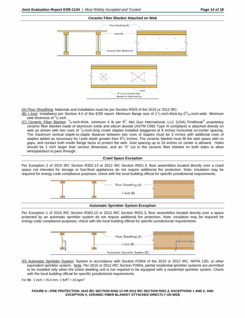
Ceramic Fiber Blanket Attached on Web
Floor Sheathing (A)
I-Joist (B)
Ceramic Fiber Blanket (C)
I-Joist“X” Cut in Ceramic Fiber Blanket for Web Hole Cut
(A) Floor Sheathing: Materials and installation must be per Section R503 of the 2015 or 2012 IRC. (B) I-Joist: Installation per Section 4.0 of this ESR report. Minimum flange size of 11/2-inch-thick-by-25/16-inch-wide. Minimum
web thickness of 3/8 inch. (C) Ceramic Fiber Blanket: 3/4-inch-thick, minimum 4 lb per ft3, Mei Guo International, LLC (USA) FireBreak® proprietary
ceramic fiber blanket made of aluminum oxide and silicon dioxide (ASTM C892 Type III compliant) is attached directly on web as shown with two rows of 7/8-inch-long crown staples installed staggered at 8 inches horizontal on-center spacing. The maximum vertical staple-to-staple distance between two rows of staples must be 3 inches with additonal rows of staples added as necessary for i-joist depth greater then 91/2 inches. The ceramic blanket must fill the web space with no gaps, and contact both inside flange faces to protect the web. Joist spacing up to 24 inches on center is allowed. Holes should be 1 inch larger than service dimension, and an “X” cut in the ceramic fiber blanket on both sides to allow wire/pipe/duct to pass through.
Crawl Space Exception
Per Exception 2 of 2015 IRC Section R302.13 or 2012 IRC Section R501.3, floor assemblies located directly over a crawl space not intended for storage or fuel-fired appliances do not require additional fire protection. Note: insulation may be required for energy code compliance purposes; check with the local building official for specific jurisdictional requirements.
Automatic Sprinkler System Exception
Per Exception 1 of 2015 IRC Section R302.13 or 2012 IRC Section R501.3, floor assemblies located directly over a space protected by an automatic sprinkler system do not require additional fire protection. Note: insulation may be required for energy code compliance purposes; check with the local building official for specific jurisdictional requirements.
(D) Automatic Sprinkler System: System in accordance with Section P2904 of the 2015 or 2012 IRC, NFPA 13D, or other
equivalent sprinkler system. Note: Per 2015 or 2012 IRC Section P2904, partial residential sprinkler systems are permitted to be installed only when the entire dwelling unit is not required to be equipped with a residential sprinkler system. Check with the local building official for specific jurisdictional requirements.
For SI: 1 inch = 25.4 mm, 1 lb/ft3 = 16 kg/m3
FIGURE 6—FIRE PROTECTION: 2015 IRC SECTION R302.13 OR 2012 IRC SECTION R501.3, EXCEPTIONS 1 AND 2, AND EXCEPTION 4; CERAMIC FIBER BLANKET ATTACHED DIRECTLY ON WEB
Joint Evaluation Report ESR-1144 | Most Widely Accepted and Trusted Page 15 of 18
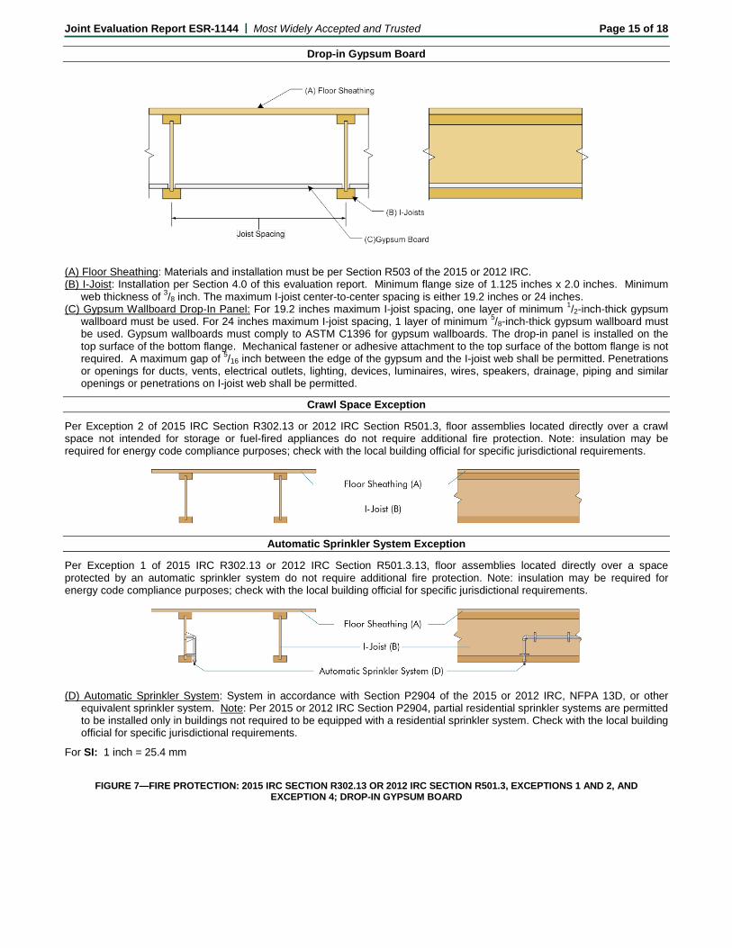
Drop-in Gypsum Board
(A) Floor Sheathing: Materials and installation must be per Section R503 of the 2015 or 2012 IRC. (B) I-Joist: Installation per Section 4.0 of this evaluation report. Minimum flange size of 1.125 inches x 2.0 inches. Minimum
web thickness of 3/8 inch. The maximum I-joist center-to-center spacing is either 19.2 inches or 24 inches. (C) Gypsum Wallboard Drop-In Panel: For 19.2 inches maximum I-joist spacing, one layer of minimum 1/2-inch-thick gypsum
wallboard must be used. For 24 inches maximum I-joist spacing, 1 layer of minimum 5/8-inch-thick gypsum wallboard must be used. Gypsum wallboards must comply to ASTM C1396 for gypsum wallboards. The drop-in panel is installed on the top surface of the bottom flange. Mechanical fastener or adhesive attachment to the top surface of the bottom flange is not required. A maximum gap of 5/16 inch between the edge of the gypsum and the I-joist web shall be permitted. Penetrations or openings for ducts, vents, electrical outlets, lighting, devices, luminaires, wires, speakers, drainage, piping and similar openings or penetrations on I-joist web shall be permitted.
Crawl Space Exception
Per Exception 2 of 2015 IRC Section R302.13 or 2012 IRC Section R501.3, floor assemblies located directly over a crawl space not intended for storage or fuel-fired appliances do not require additional fire protection. Note: insulation may be required for energy code compliance purposes; check with the local building official for specific jurisdictional requirements.
Automatic Sprinkler System Exception
Per Exception 1 of 2015 IRC R302.13 or 2012 IRC Section R501.3.13, floor assemblies located directly over a space protected by an automatic sprinkler system do not require additional fire protection. Note: insulation may be required for energy code compliance purposes; check with the local building official for specific jurisdictional requirements.
(D) Automatic Sprinkler System: System in accordance with Section P2904 of the 2015 or 2012 IRC, NFPA 13D, or other
equivalent sprinkler system. Note: Per 2015 or 2012 IRC Section P2904, partial residential sprinkler systems are permitted to be installed only in buildings not required to be equipped with a residential sprinkler system. Check with the local building official for specific jurisdictional requirements.
For SI: 1 inch = 25.4 mm
FIGURE 7—FIRE PROTECTION: 2015 IRC SECTION R302.13 OR 2012 IRC SECTION R501.3, EXCEPTIONS 1 AND 2, AND EXCEPTION 4; DROP-IN GYPSUM BOARD
Joint Evaluation Report ESR-1144 | Most Widely Accepted and Trusted Page 16 of 18
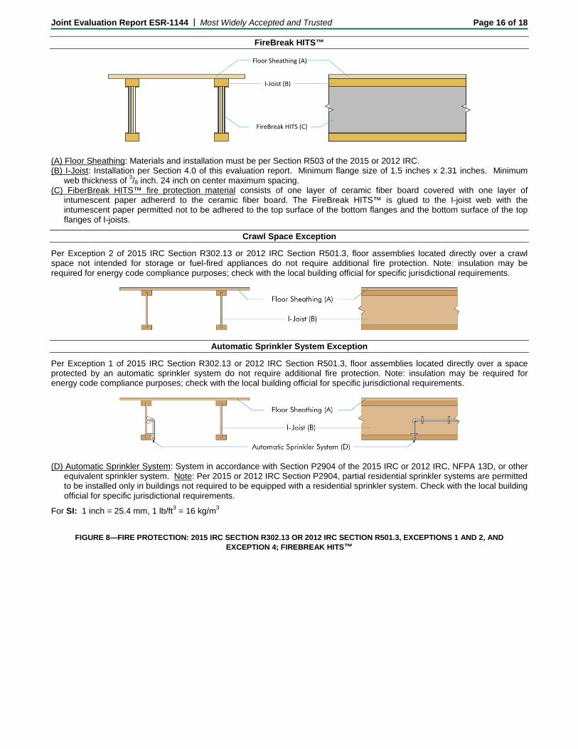
FireBreak HITS™
Floor Sheathing (A)
I-Joist (B)
FireBreak HITS (C)
(A) Floor Sheathing: Materials and installation must be per Section R503 of the 2015 or 2012 IRC. (B) I-Joist: Installation per Section 4.0 of this evaluation report. Minimum flange size of 1.5 inches x 2.31 inches. Minimum
web thickness of 3/8 inch. 24 inch on center maximum spacing. (C) FiberBreak HITS™ fire protection material consists of one layer of ceramic fiber board covered with one layer of
intumescent paper adhererd to the ceramic fiber board. The FireBreak HITS™ is glued to the I-joist web with the intumescent paper permitted not to be adhered to the top surface of the bottom flanges and the bottom surface of the top flanges of I-joists.
Crawl Space Exception
Per Exception 2 of 2015 IRC Section R302.13 or 2012 IRC Section R501.3, floor assemblies located directly over a crawl space not intended for storage or fuel-fired appliances do not require additional fire protection. Note: insulation may be required for energy code compliance purposes; check with the local building official for specific jurisdictional requirements.
Automatic Sprinkler System Exception
Per Exception 1 of 2015 IRC Section R302.13 or 2012 IRC Section R501.3, floor assemblies located directly over a space protected by an automatic sprinkler system do not require additional fire protection. Note: insulation may be required for energy code compliance purposes; check with the local building official for specific jurisdictional requirements.
(D) Automatic Sprinkler System: System in accordance with Section P2904 of the 2015 IRC or 2012 IRC, NFPA 13D, or other
equivalent sprinkler system. Note: Per 2015 or 2012 IRC Section P2904, partial residential sprinkler systems are permitted to be installed only in buildings not required to be equipped with a residential sprinkler system. Check with the local building official for specific jurisdictional requirements.
For SI: 1 inch = 25.4 mm, 1 lb/ft3 = 16 kg/m3
FIGURE 8—FIRE PROTECTION: 2015 IRC SECTION R302.13 OR 2012 IRC SECTION R501.3, EXCEPTIONS 1 AND 2, AND EXCEPTION 4; FIREBREAK HITS™
Joint Evaluation Report ESR-1144 | Most Widely Accepted and Trusted Page 17 of 18
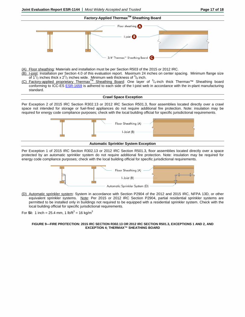
Factory-Applied ThermaxTM Sheathing Board
(A) Floor sheathing: Materials and installation must be per Section R503 of the 2015 or 2012 IRC. (B) I-joist: Installation per Section 4.0 of this evaluation report. Maximum 24 inches on center spacing. Minimum flange size
of 11/2 inches thick x 21/2 inches wide. Minimum web thickness of 3/8 inch. (C) Factory-applied proprietary ThermaxTM Sheathing Board: One layer of 3/4-inch thick Thermax™ Sheathing board
conforming to ICC-ES ESR-1659 is adhered to each side of the I-joist web in accordance with the in-plant manufacturing standard.
Crawl Space Exception
Per Exception 2 of 2015 IRC Section R302.13 or 2012 IRC Section R501.3, floor assemblies located directly over a crawl space not intended for storage or fuel-fired appliances do not require additional fire protection. Note: insulation may be required for energy code compliance purposes; check with the local building official for specific jurisdictional requirements.
Automatic Sprinkler System Exception
Per Exception 1 of 2015 IRC Section R302.13 or 2012 IRC Section R501.3, floor assemblies located directly over a space protected by an automatic sprinkler system do not require additional fire protection. Note: insulation may be required for energy code compliance purposes; check with the local building official for specific jurisdictional requirements.
(D) Automatic sprinkler system: System in accordance with Section P2904 of the 2012 and 2015 IRC, NFPA 13D, or other
equivalent sprinkler systems. Note: Per 2015 or 2012 IRC Section P2904, partial residential sprinkler systems are permitted to be installed only in buildings not required to be equipped with a residential sprinkler system. Check with the local building official for specific jurisdictional requirements.
For SI: 1 inch = 25.4 mm, 1 lb/ft3 = 16 kg/m3
FIGURE 9—FIRE PROTECTION: 2015 IRC SECTION R302.13 OR 2012 IRC SECTION R501.3, EXCEPTIONS 1 AND 2, AND EXCEPTION 4; THERMAX™ SHEATHING BOARD
Joint Evaluation Report ESR-1144 | Most Widely Accepted and Trusted Page 18 of 18
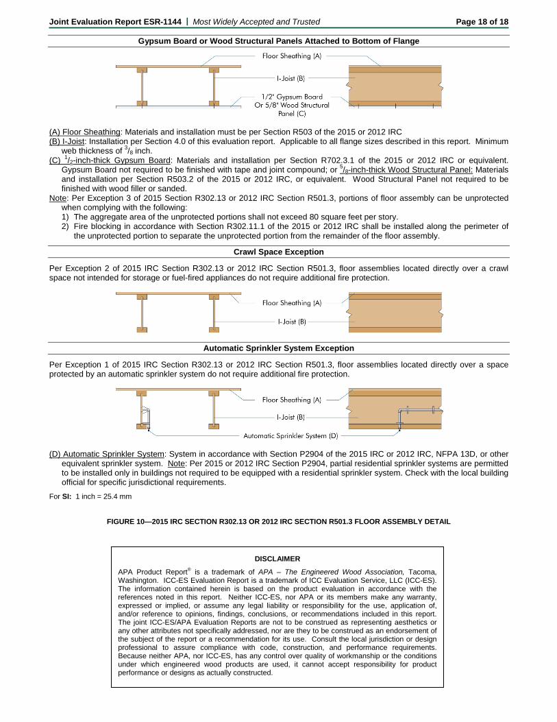
Gypsum Board or Wood Structural Panels Attached to Bottom of Flange
(A) Floor Sheathing: Materials and installation must be per Section R503 of the 2015 or 2012 IRC (B) I-Joist: Installation per Section 4.0 of this evaluation report. Applicable to all flange sizes described in this report. Minimum
web thickness of 3/8 inch. (C) 1/2-inch-thick Gypsum Board: Materials and installation per Section R702.3.1 of the 2015 or 2012 IRC or equivalent.
Gypsum Board not required to be finished with tape and joint compound; or 5/8-inch-thick Wood Structural Panel: Materials and installation per Section R503.2 of the 2015 or 2012 IRC, or equivalent. Wood Structural Panel not required to be finished with wood filler or sanded.
Note: Per Exception 3 of 2015 Section R302.13 or 2012 IRC Section R501.3, portions of floor assembly can be unprotected when complying with the following: 1) The aggregate area of the unprotected portions shall not exceed 80 square feet per story. 2) Fire blocking in accordance with Section R302.11.1 of the 2015 or 2012 IRC shall be installed along the perimeter of
the unprotected portion to separate the unprotected portion from the remainder of the floor assembly.
Crawl Space Exception
Per Exception 2 of 2015 IRC Section R302.13 or 2012 IRC Section R501.3, floor assemblies located directly over a crawl space not intended for storage or fuel-fired appliances do not require additional fire protection.
Automatic Sprinkler System Exception
Per Exception 1 of 2015 IRC Section R302.13 or 2012 IRC Section R501.3, floor assemblies located directly over a space protected by an automatic sprinkler system do not require additional fire protection.
(D) Automatic Sprinkler System: System in accordance with Section P2904 of the 2015 IRC or 2012 IRC, NFPA 13D, or other
equivalent sprinkler system. Note: Per 2015 or 2012 IRC Section P2904, partial residential sprinkler systems are permitted to be installed only in buildings not required to be equipped with a residential sprinkler system. Check with the local building official for specific jurisdictional requirements.
For SI: 1 inch = 25.4 mm
FIGURE 10—2015 IRC SECTION R302.13 OR 2012 IRC SECTION R501.3 FLOOR ASSEMBLY DETAIL
DISCLAIMER
APA Product Report® is a trademark of APA – The Engineered Wood Association, Tacoma, Washington. ICC-ES Evaluation Report is a trademark of ICC Evaluation Service, LLC (ICC-ES). The information contained herein is based on the product evaluation in accordance with the references noted in this report. Neither ICC-ES, nor APA or its members make any warranty, expressed or implied, or assume any legal liability or responsibility for the use, application of, and/or reference to opinions, findings, conclusions, or recommendations included in this report. The joint ICC-ES/APA Evaluation Reports are not to be construed as representing aesthetics or any other attributes not specifically addressed, nor are they to be construed as an endorsement of the subject of the report or a recommendation for its use. Consult the local jurisdiction or design professional to assure compliance with code, construction, and performance requirements. Because neither APA, nor ICC-ES, has any control over quality of workmanship or the conditions under which engineered wood products are used, it cannot accept responsibility for product performance or designs as actually constructed.