Embed Size (px)
Citation preview

JOHNSON MATTHEY TECHNOLOGY REVIEW
Johnson Matthey’s international journal of research exploring science and technology in industrial applications
www.technology.matthey.com
SPECIAL ISSUE 13 ‘200th Anniversary of Johnson Matthey’ July 2017Published by Johnson Matthey
ISSN 2056-5135

www.technology.matthey.com
© Copyright 2017 Johnson Matthey
Johnson Matthey Technology Review is published by Johnson Matthey Plc.
This work is licensed under a Creative Commons Attribution-NonCommercial-NoDerivatives 4.0 International License. You may share, copy and redistribute the material in any medium or format for any lawful purpose. You must give appropriate credit to the author and publisher. You may not use the material for commercial purposes without prior permission. You may not distribute modified material without prior permission.
The rights of users under exceptions and limitations, such as fair use and fair dealing, are not affected by the CC licenses.

Contents SPECIAL ISSUE 13 ‘200th Anniversary of Johnson Matthey’ July 2017
JOHNSON MATTHEY TECHNOLOGY REVIEW
Johnson Matthey’s international journal of research exploring science and technology in industrial applications
www.technology.matthey.com
“The Founding of Johnson Matthey” Two Hundred Proud Years – the Bicentenary of Johnson Matthey
By W. P. Griffith Original publication: Johnson Matthey Technol. Rev., 2017, 61, (3), 257
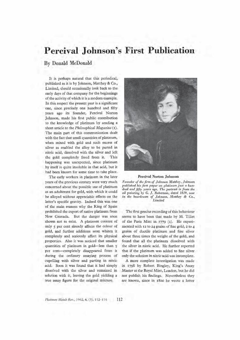
Percival Johnson’s First Publication By Donald McDonald Original publication: Platinum Metals Rev., 1962, 6, (3), 112
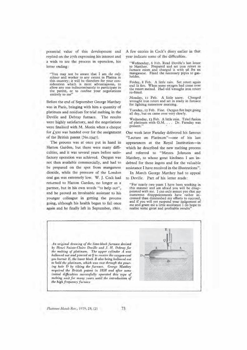
George Matthey and the Building of the Platinum Industry By L. B. Hunt Original publication: Platinum Metals Rev., 1979, 23, (2), 68
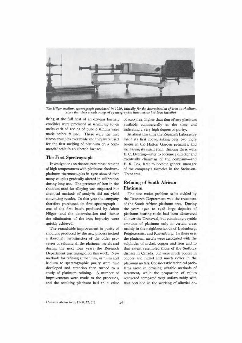
“Research and Collaboration at Johnson Matthey” Fifty Years of Research on the Platinum Metals
By A. R. Powell Original publication: Platinum Metals Rev., 1968, 12, (1), 22
The New Johnson Matthey Research Centre By Ian E. Cottington Original publication: Platinum Metals Rev., 1976, 20, (3), 74
“Industrial Developments to the Present Day” The Beginnings of Chemical Engineering By Donald McDonald Original publication: Platinum Metals Rev., 1957, 1, (2), 51
Note: all page numbers are as originally published

Contents (continued)
JOHNSON MATTHEY TECHNOLOGY REVIEW
Johnson Matthey’s international journal of research exploring science and technology in industrial applications
www.technology.matthey.com
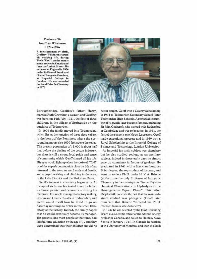
Geoffrey Wilkinson and Platinum Metals Chemistry By M. L. H. Green and W. P. Griffith Original publication: Platinum Metals Rev., 1998, 42, (4), 168
Enhancement of Industrial Hydroformylation Processes by the Adoption of Rhodium-Based Catalyst: Part I By Richard Tudor and Michael Ashley
Original publication: Platinum Metals Rev., 2007, 51, (3), 116
40 Years of Cleaner Air: The Evolution of the Autocatalyst By Chris Morgan
Original publication: Platinum Metals Rev., 2014, 58, (4), 217
The 1980 MacRobert Award Original publication: Platinum Metals Rev., 1981, 25, (1), 22
The Role of Platinum in Proton Exchange Membrane Fuel Cells By Oliver T. Holton and Joseph W. Stevenson
Original publication: Platinum Metals Rev., 2013, 57, (4), 259
Automotive Lithium-Ion Batteries By Peter Miller
Original publication: Johnson Matthey Technol. Rev., 2015, 59, (1), 4
Platinum Group Metal Compounds in Cancer Chemotherapy By Christopher Barnard
Original publication: Johnson Matthey Technol. Rev., 2017, 61, (1), 52
Note: all page numbers are as originally published

www.technology.matthey.comJOHNSON MATTHEY TECHNOLOGY REVIEW
https://doi.org/10.1595/205651317X695884 Johnson Matthey Technol. Rev., 2017, 61, (3), 257–261
257 © 2017 Johnson Matthey
W. P. GriffithDepartment of Chemistry, Imperial College, London SW7 2AZ, UK
Email: [email protected]
The story of the first 200 years of Johnson Matthey is told. The firm was started in 1817 by Percival Johnson, but in 1851 George Matthey became a partner and the present name was derived from these two partners. A number of milestones in its illustrious history are reviewed, and some of the current activities of the company are brought up to date, in this short article.
Introduction
Thirty-five years ago a magisterial volume was published by Johnson Matthey on “A History of Platinum and its Allied Metals”, but despite its title that book is also a history of the firm itself from 1817 to 1982 (1). The present account marks Johnson Matthey’s bicentenary, and is much indebted to that volume; many aspects of the story have also been chronicled by Platinum Metals Review and its 2014 successor, the Johnson Matthey Technology Review. Appropriate references to these journals are given wherever possible. A Platinum Metals Review paper marking the firm’s sesquicentenary was published in 1967 (2), and a recent paper notes that Johnson Matthey is one of the oldest British chemical firms still in existence (3). In this survey we concentrate on the firm’s formative years and, while highlighting its activities with platinum group metals (pgms), include
some of Johnson Matthey’s considerable recent non-pgm activities.
The Johnsons of Maiden Lane
The forebears of Percival Norton Johnson, who in 1817 became the founder of the precursor of Johnson Matthey, came from a family well acquainted with metal assaying and refining (4, 5). His grandfather John Johnson (1737–1786) had since 1777 been an assayer of ores and metals, mostly silver, gold and some base metals, at No. 7, Maiden Lane (now part of Gresham Street between Wood Street and Foster Lane, London EC2). His son, also John Johnson (1765–1831) was apprenticed to him in 1779, and on his father’s death took over his business, becoming the only commercial assayer in London. Around 1800 he became involved with the rapidly developing platinum metals industry, using crude ‘platina’ smuggled to Britain via Jamaica from what is now Colombia. His biggest early customer was probably William Hyde Wollaston (1766–1826) (6), who made many purchases of platina between 1802–1819 from Johnson. Wollaston developed a secret process for isolating platinum so pure that it could be fashioned into crucibles, chalices and other vessels and drawn into wires much thinner than a human hair; this business made him wealthy. In addition to isolating rhodium and palladium in 1802 (6, 7), he sold to his friend and partner Smithson Tennant some ore from which Tennant in 1804 isolated iridium and osmium (8, 9).
Percival Norton Johnson (1792–1866), was born on 29th September 1792 at 6–7 Maiden Lane and was
Two Hundred Proud Years – the Bicentenary of Johnson MattheyOrigins of the company and of today’s research activities in science and technology

258 © 2017 Johnson Matthey
https://doi.org/10.1595/205651317X695884 Johnson Matthey Technol. Rev., 2017, 61, (3)
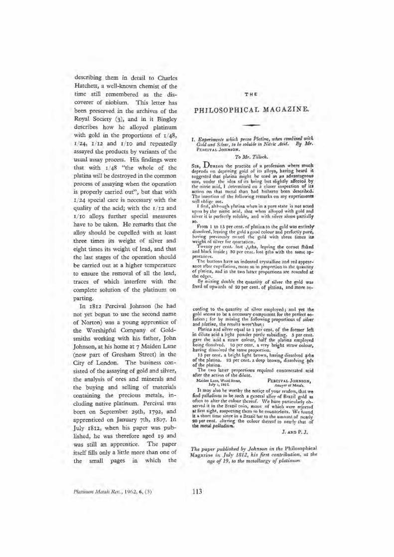
apprenticed to his father John Johnson. In 1812, aged only 19, he established his scientific credentials in a paper showing that platinum alloyed with silver and gold would dissolve in nitric acid (10, 11).
The Early Years of Percival Johnson’s New Firm
The date of foundation of what 34 years later would be called Johnson Matthey is established as January 1st 1817 (1, 2). On that day Percival Johnson left his father’s business and set up his own business as an ‘Assayer and Practical Mineralogist’ with his brother John Frederick as assistant, although he would later collaborate with his father (2). The year 1817 was also that in which Humphry Davy showed that a platinum wire (almost certainly provided by Johnson) would catalyse the combination of oxygen and hydrogen – the first demonstration of heterogeneous catalysis (12, 13).
In 1818 Percival moved to 8 Maiden Lane and in 1822 to 79 Hatton Garden, the latter being expanded in 1850. In 1826 he brought in another talented assayer, John Stokes, renaming the firm Johnson and Stokes in 1832. When Stokes died in 1835, William John Cock (1813–1892), like Percival Johnson a founder member of the Chemical Society in 1841 (14), joined Percival in the firm which was now called Johnson and Cock. William was the son of Thomas Cock (1782–1842), Percival’s brother-in-law, also an assayer.
William Cock was a considerable chemist and metallurgist, devising a new procedure for increasing the malleability of platinum, and published ‘On Palladium – Its Extraction, Alloys &c.’ (15, 16) in one of the earliest of the Chemical Society’s papers. Johnson and Cock produced a platinum medal for Queen Victoria’s coronation in 1838, and in 1844 made the platinum from which the standard pound weight was made. Cock resigned in 1845 from ill-health, but continued collaboration; Johnson’s firm was now called P. N. Johnson & Co (1).
Johnson’s Firm Renamed Johnson and Matthey
In 1838 Johnson and Cock apprenticed the second person commemorated in the present firm’s name, George Matthey (1825–1913) (17). Just thirteen when they first employed him, he quickly became interested in platinum and Cock took him under his wing. Matthey had a shrewd business mind as well as an excellent knowledge of chemistry and metallurgy, and he
persuaded a reluctant Johnson to exhibit samples of platinum, palladium, rhodium and iridium at the Great Exhibition of 1851, for which they were awarded a prize. Johnson took him into partnership in the same year and renamed the firm Johnson and Matthey. In 1846 Percival Johnson was elected a Fellow of the Royal Society (FRS), his election being supported by Michael Faraday (to whom the firm had given an ingot of platinum and some platinum wire for a famous Royal Institution discourse).
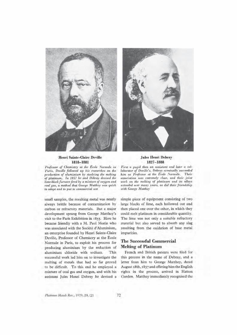
In 1852 Johnson Matthey was appointed official assayer to the Bank of England followed by official refiner in 1861. A key event in the firm’s history was Matthey’s collaboration with Jules Henri Debray (1827–1888) for melting platinum on a large scale (18). At the Paris Exhibition of 1867, Johnson Matthey was awarded two gold medals for its fine display of some 15,000 ounces of pgms in many forms, and as a result George Matthey became a Chevalier of the Légion d’Honneur, one of France’s highest honours. In 1874 the firm made the first standard metre and standard kilogram in 10% iridium-90% platinum alloy for the International Metric Commission. This kilogram is still the standard measure and will be so until late 2018 when it will be defined using a more modern technique. It is now held in the the Bureau international des poids et mesures in Sèvres (19). In a rare departure at the time from pgms, Johnson Matthey almost certainly provided the high purity aluminium for the statue known as Eros, erected in 1892 in Piccadilly Circus (20).
In 1879 Matthey was awarded an FRS: like Johnson and Cock he had published several papers, including an important one on the removal of rhodium and iridium from platinum, and the preparation of a platinum-iridium alloy (21). Both he and Johnson are commemorated in the new “Oxford Dictionary of National Biography” (22, 23). Like Johnson, George Matthey was a great supporter of the Chemical Society, thus continuing a long and still current association between the Society (now the Royal Society of Chemistry) and Johnson Matthey (14).
In 1860 George Matthey’s brother Edward (1836–1918) was appointed a junior partner: he had studied under Hofmann at the Royal College of Chemistry. Another partner was John Scudamore Sellon (1836–1918), a nephew of Johnson’s wife, who had commercial experience; the firm was now renamed Johnson Matthey and Co (1). On 1st June 1866 Percival Johnson died (22); George Matthey wrote an obituary (published in the Anniversary meeting

259 © 2017 Johnson Matthey
https://doi.org/10.1595/205651317X695884 Johnson Matthey Technol. Rev., 2017, 61, (3)
of the Chemical Society, March 30th, 1867, page 392 (24)). George Matthey retired in 1909 after a 70-year career; and died on 14th February 1913 (23, 25). John Sellon replaced him as chairman, but died in 1918 as did Edward Matthey. The Matthey succession on the company’s board was secured by George’s son Percy St. Clair Matthey (1862–1928) and, from 1928, by Edward Matthey’s son Hay Whitworth Pierre Matthey (1876–1957), chairman until 1957 (1).
Johnson Matthey became a limited company in 1891 and its ordinary shares were first listed on the London Stock Exchange in 1942. It subsequently opened businesses in the USA (1927); Australia and New Zealand (1948); across Europe (in the 1950s); India (1964); Japan (1969); Mexico and Malaysia (1995) and in China (2001). There are now Johnson Matthey operations in over 30 countries.
Sources of Platinum Group Metals
John and Percival Johnson used platina smuggled into Britain by speculators from the Choco district of what is now Colombia from ca. 1780–1830. After Colombia became independent of Spain less platina found its way to Europe and Johnson Matthey seems to have used Russian supplies from around 1850 (1) and, early in the 20th century, Canadian sources from Ontario (2). Everything changed though with the discovery of huge reserves of pgm-bearing ore in South Africa, first found there in 1906 (26). In 1925 the huge South African Merensky Reef which contains some 80% of the world’s reserves of pgms was discovered, and by 1931 Johnson Matthey took and continued to take pgms from the mines in the Rustenburg region, 100 km west of Pretoria (27), for many years. In 1925 the ground-breaking Powell-Deering smelting and refining process for Rustenburg ore was developed by Johnson Matthey. A refinery was set up in Brimsdown, near Enfield, UK, in 1928. This is still in use, though primary refining of South African pgm-containing ores is done in South Africa. Some primary refining is carried out by Johnson Matthey. However the company remains the world’s largest secondary refiner of pgms, with refineries in Royston and Brimsdown in the UK, West Deptford in the USA and in China.
Johnson Matthey in the 20th and 21st Centuries
Until the late 19th century Johnson Matthey was mainly concerned with relatively small-scale applications
of platinum and other pgms, and though admired, particularly in France, was relatively little known abroad. It is now a major international company dealing with many aspects of pgm and non-pgm technologies. Major factors leading to this were the establishment of a plentiful source of pgms, the foundation of an outstanding research department, and its later diversification with non-pgm technology.
Johnson Matthey’s Research Department, and Collaboration with Academic Institutions
In 1918 Alan Richard Powell (1894–1975) established a research department at Johnson Matthey and was for 36 years its Research Manager; he was awarded an FRS in 1953 (28). The department initially occupied two rooms at Hatton Garden but in 1938 moved to Wembley, and then in 1976 to its present location at Sonning Common, near Reading (29). Powell wrote an account of the first fifty years of his department (30).
Early in the 20th century Johnson Matthey launched an unusual initiative, later called the Johnson Matthey Loan Scheme, of which the author was for many years a beneficiary, as were many others in university and other departments worldwide. Compounds of rare materials, mainly pgms, were given, without charge, to bona fide researchers for work on innovative science. Researchers were free to publish their material, the only stipulation being that the residues of material used were returned to Johnson Matthey (31). Much useful work resulted from this; a good example being that of the late Sir Geoffrey Wilkinson (FRS and Nobel laureate) whose extensive work on synthesis and homogeneous catalysis by pgm complexes would have been impossible without the scheme (32, 33). The scheme has been replaced by one in which Johnson Matthey continues to collaborate with universities and others, and often provides research materials.
In 1957 the quarterly Platinum Metals Review was founded by Johnson Matthey; after 58 years of production it became the Johnson Matthey Technology Review in mid-2014, partly to signal that much of the company’s current research and applications are no longer pgm-based. Volume numbers remain as for Platinum Metals Review.
Areas of Prime Development in Johnson Matthey
The company is actively involved with many areas

260 © 2017 Johnson Matthey
https://doi.org/10.1595/205651317X695884 Johnson Matthey Technol. Rev., 2017, 61, (3)
including automotive emission control catalysts, homogeneous and heterogeneous catalysis for petroleum refining, oxidation of ammonia to nitric acid, manufacture of active pharmaceutical ingredients, components for glass manufacture, thermocouples and advanced battery materials, fuel cells and water purification, and much more. Johnson Matthey states that its focus today as it celebrates its 200th year is on the global priorities of cleaner air, the efficient use of natural resources and improved health (34, 35). Here we briefly note some aspects of Johnson Matthey’s research and production in these areas.
Clean Air: Automotive
Johnson Matthey was and is a leader since the 1960s in conversion of the toxic components of vehicle exhaust gases – hydrocarbons, carbon monoxide and oxides of nitrogen (NOx) – to carbon dioxide, water and nitrogen; there has also been much progress with diesel emissions and particulates (36–38) and with removal of alkenes and alkynes from automotive emissions. In 1977 Johnson Matthey was presented with the Queen’s Award for Technological Achievement for its pioneering work in emissions control (39). The company now accounts for one in three of the catalysts on cars around the world.
A non-pgm area of research and production is the design and manufacture of low-power low-capacity batteries for industrial and leisure uses and high-power high-capacity batteries for automotive applications, such as high performance hybrid and plug-in hybrid vehicles. Most of these are lithium-ion based. The first themed issue of Johnson Matthey Technology Review in 2015 was devoted to battery technologies (40, 41).
Efficient Use of Natural Resources
In 2002 ICI sold its Synetix process catalysts business along with its Tracerco subsidiary to Johnson Matthey. The process catalysts business provided Johnson Matthey with a strong global position in non-precious metal catalysts used in a wide range of major chemical manufacturing processes, an area that has been strengthened by further acquisitions. In 2006 Johnson Matthey bought Davy Process Technology (DPT), thus strengthening its position as a catalyst and technology supplier to the world’s chemical and energy industries. Some of the many processes involved include the catalysed conversion of syngas (carbon monoxide,
carbon dioxide and hydrogen) to methanol; oxo alcohols from hydroformylation reactions involving alkene oxidations with syngas; and the production of biodiesel.
Health: Chemotherapy
Another area in which Johnson Matthey played an important early and continuing part was the use of pgm complexes, particularly of platinum, in the treatment of malignant cancers, starting in 1983. First-generation (cisplatin), and many second- and third-generation drugs have been made and investigated by the company, and very recently reviewed (42). In 1993 Johnson Matthey bought Meconic, a holding company for the pharmaceutical company MacFarlan Smith, and this became part of Johnson Matthey; a major interest now is the synthesis of pharmaceuticals often without pgm-based technology.
Conclusions
The origins of Johnson Matthey – founded in 1817 by Percival Johnson and later strengthened by the appointment of George Matthey – have been described with some of its principal achievements over the last two centuries. The focus of the company in the 21st century which has grown to include many non-pgm technologies has been highlighted.
Acknowledgement
The author thanks Dan Carter and Ian Godwin for their help in providing information on some of the latest initiatives at Johnson Matthey.
References1. D. McDonald and L. B. Hunt, “A History of Platinum
and its Allied Metals”, Johnson Matthey, London, UK, 1982, pp 450
2. D. McDonald, Platinum Metals Rev., 1967, 11, (1), 18
3. A. Extance, Chemistry World, 2017, 14, (5), 22
4. D. McDonald, “The Johnsons of Maiden Lane”, Martins Publishers Ltd, London, UK, 1964, 180 pp
5. D. McDonald, “Percival Norton Johnson, the Biography of a Pioneering Metallurgist”, Johnson Matthey, London, UK, 1951, 224 pp
6. M. C. Usselman, “Pure Intelligence: The Life of William Hyde Wollaston”, The University of Chicago,

261 © 2017 Johnson Matthey
https://doi.org/10.1595/205651317X695884 Johnson Matthey Technol. Rev., 2017, 61, (3)
Chicago, USA, 2015, pp 424
7. W. P. Griffith, Platinum Metals Rev., 2003, 47, (4), 175
8. W. P. Griffith, Platinum Metals Rev., 2004, 48, (4), 182
9. L. B. Hunt, Platinum Metals Rev., 1987, 31, (1), 32
10. P. Johnson, Phil. Mag., 1812, 40, (171), 3
11. D. McDonald, Platinum Metals Rev., 1962, 6, (3), 112
12. H. Davy, Phil. Trans. R. Soc. Lond., 1817, 107, 77
13. L. B. Hunt, Platinum Metals Rev., 1979, 23, (1), 29
14. W. P. Griffith, Platinum Metals Rev., 2013, 57, (2), 110
15. W. J. Cock, Mem. Chem. Soc., Lond., 1843, 1, 161
16. L. B. Hunt, Platinum Metals Rev., 1983, 27, (3), 129
17. L. B. Hunt, Platinum Metals Rev., 1979, 23, (2), 68
18. W. P. Griffith, Platinum Metals Rev., 2009, 53, (4), 209
19. T. J. Quinn, Platinum Metals Rev., 1986, 30, (2), 74
20. D. McDonald, “The History of Johnson, Matthey & Co. Limited”, Volume 1, Johnson Matthey, London, UK, 196X
21. G. Matthey, Proc. R. Soc. Lond., 1878, 28, (190–195), 463
22. I. E. Cottington, ‘Johnson, Percival Norton (1792–1866)’, “Oxford Dictionary of National Biography”, Oxford University Press, Oxford, UK, 2004
23. I. E. Cottington, ‘Matthey, George (1825–1913)’, “Oxford Dictionary of National Biography”, Oxford University Press, Oxford, UK, 2004
24. J. Chem. Soc., 1867, 20, 385
25. L. W. Stansell, F. S. Kipping, A. G. Perkin, C. A. Keane, A. P. Laurie, A. R. Ling and T. K. Rose, J. Chem. Soc., Trans., 1914, 105, 1189
26. R. G. Cawthorn, Platinum Metals Rev., 2006, 50, (3), 130
27. J. T. Bruce, Platinum Metals Rev., 1996, 40, (1), 2
28. G. V. Raynor, Biogr. Mems. Fell. R. Soc., 1976, 22, 307
29. I. E. Cottington, Platinum Metals Rev., 1976, 20, (3), 74
30. A. R. Powell, Platinum Metals Rev.,1968, 12, (1), 22
31. D. T. Thompson, Platinum Metals Rev., 1987, 31, (4), 171
32. M. L. H. Green and W. P. Griffith, Platinum Metals Rev., 1998, 42, (4), 168
33. H. Gay and W. P. Griffith, “The Chemistry Department
at Imperial College: A History 1845–2000”, World Scientific Publishing Europe Ltd, London, UK, 2017, 584 pp
34. ‘Johnson Matthey at 200 – Aligned for Growth’, Johnson Matthey, London, UK, 20th April, 2017
35. ‘A New Brand, 200 Years in the Making: Johnson Matthey Reveals Refreshed Identity’, Johnson Matthey, London, UK, 8th May, 2017
36. A. Raj, Johnson Matthey Technol. Rev., 2016, 60, (4), 228
37. C. Morgan, Johnson Matthey Technol. Rev., 2014, 58, (4), 217
38. M. V. Twigg and P. R. Phillips, Platinum Metals Rev., 2009, 53, (1), 27
39. Platinum Metals Rev., 1977, 21, (3), 84
40. M. Green, Johnson Matthey Technol. Rev., 2015, 59, (1), 2
41. P. Miller, Johnson Matthey Technol. Rev., 2015, 59, (1), 4
42. C. Barnard, Johnson Matthey Technol. Rev., 2017, 61, (1), 52
The Author
Bill Griffith is an Emeritus Professor of Chemistry at Imperial College, London, UK. He has much experience with the platinum group metals, particularly ruthenium and osmium. He has published over 270 research papers, many describing complexes of these metals as catalysts for specific organic oxidations. He has written eight books on the platinum metals, and has published, with Hannah Gay, a history of the 170-year old chemistry department at Imperial College (33). He is responsible for Membership at the Historical Group of the Royal Society of Chemistry.


116
2-Ethylhexanol (2EH) is the most widely used(‘workhorse’) plasticiser alcohol, and butanols –the normal and iso isomers – are used as solventsor chemical intermediates. Both 2EH andbutanols are derivatives of butyraldehyde madefrom propylene by hydroformylation. From theearly 1940s until the early 1980s, the world’s majorproducers of 2EH and butanols operated propy-lene hydroformylation (often termed ‘oxo’)processes for producing the required butyr-aldehyde using a cobalt catalyst system. This deliv-ered poor conversion and low selectivity of theprincipal feedstock, propylene, to the desiredproducts, in complex and cumbersome plantsoperating at high pressure.
The ‘Low Pressure Oxo’ process (LP OxoSM
Process) was developed and then licensed to theoxo industry through a tripartite collaboration
beginning in 1971. The principals were JohnsonMatthey & Co. Ltd. (now Johnson Matthey PLC),The Power-Gas Corporation Ltd. (a former nameof Davy Process Technology Ltd., now a sub-sidiary of Johnson Matthey PLC) and UnionCarbide Corporation (now a subsidiary of TheDow Chemical Company). Using rhodium-basedcatalysis, the LP OxoSM Process offered such greateconomic advantages over the established cobalt-catalysed processes, as well as technical elegance,that many cobalt systems were replaced by brandnew plants. In the thirty years or so since the LPOxoSM Process was first introduced, it has main-tained its position as the world’s foremost oxoprocess, having undergone much improvementand refinement. About two thirds of the world’sbutyraldehyde is now produced in LP OxoSM
plants. Most LP OxoSM systems are licensed
Enhancement of IndustrialHydroformylation Processes by theAdoption of Rhodium-Based Catalyst:Part IDEVELOPMENT OF THE LP OXOSM PROCESS TO THE COMMERCIAL STAGE
By Richard Tudor* and Michael AshleyDavy Process Technology Ltd., 20 Eastbourne Terrace, London W2 6LE, U.K.; *E-mail: [email protected]
The adoption of a low-pressure rhodium-based catalyst system in place of high-pressure cobaltfor the hydroformylation of propylene by reaction with carbon monoxide and hydrogen toproduce butyraldehydes (an ‘oxo’reaction) has brought large cost benefits to oxo producers.The benefits derive from improved feedstock efficiency, lower energy usage and simpler andcheaper plant configurations. The technical and commercial merits of the ‘LP OxoSM Process’for producing butyraldehydes have made it one of the best known applications of industrial-scale chemistry using a platinum group metal (pgm). Today, practically all butyraldehyde ismade by rhodium catalysis, and this should provide convincing encouragement to researcherswho are keen to exploit pgms as catalyst research materials, but are apprehensive as to theimplications of their very high intrinsic value. It should also encourage developers and designersresponsible for turning pgm chemistry into commercial processes, who may be daunted byproblems such as containment and catalyst life. This article (Part I) reviews the backgroundto the LP OxoSM Process, and its development to the point of first commercialisation.Part II, covering some of the key improvements made to the process and its use in non-propyleneapplications, will appear in a future issue of Platinum Metals Review.
Platinum Metals Rev., 2007, 51, (3), 116–126
DOI: 10.1595/147106707X216855

plants, nearly all of which have been built underlicences granted by Davy Process Technology (1)working in cooperation with The Dow ChemicalCompany (2); the remainder are plants owned andoperated by Dow’s Union Carbide subsidiary (3).
This article (Part I) reviews the background tothe LP OxoSM Process, addressing some of thechallenges that faced its developers and designersin planning the first commercial plant, and duringthe period immediately following commercialis-ation. Insights are given on the chemical functionof the homogeneous liquid-phase catalyst system.In Part II, some examples of advancements of thetechnology in the years following the first roundof licensing will be outlined.
The Beginnings of the DevelopmentCommercialisation of the LP OxoSM Process
was the culmination of an intensive joint effort inchemistry and engineering by the three compa-nies, dating back to 1964. Early exploratory workby the chemicals producer Union Carbide in theU.S.A. demonstrated promise for rhodium coordi-nation complexes in solution as hydroformylationcatalysts at low pressure, yielding a high propor-tion of the straight-chain aldehyde product andwith high enough catalyst productivity to justifyexamining the commercial potential of rhodium.The company obtained a basic patent for thiswork in 1970 (4). In operating a number of high-pressure oxo plants, Union Carbide had becomevery familiar with cobalt systems and their short-comings, and viewed the potential for rhodiumwith guarded excitement. At that time, all industri-al oxo production used the classic high-pressurecobalt process described below, or a modifi-cation of it.
Meanwhile, independent research by the lateProfessor Sir Geoffrey Wilkinson (5–7) (later towin a Nobel Prize for Chemistry) at ImperialCollege, London, supported by the precious metalrefiner and processor Johnson Matthey, producedresults using a suitable coordination complex ofrhodium (e.g. (5)) which basically reproduced orcomplemented the Union Carbide findings.Johnson Matthey in turn approached The Power-Gas Corporation (now Davy Process Technology).
The engineering contracting company drew on itsstrong background in process engineering toinvestigate the commercial potential for a low-pressure route to butyraldehyde. With thepublication of patents by Union Carbide (e.g. (4))and Johnson Matthey (e.g. (5)), the three partiesrealised that they had a common interest, so in1971 they launched a joint development pro-gramme to convert the laboratory rhodium-oxochemistry into a commercial process with a viewto exploiting its technical merit.
The focus of the collaboration was a processfor the hydroformylation of propylene using a mix-ture of carbon monoxide and hydrogen (in theform of synthesis gas) to produce normalbutyraldehyde and iso-butyraldehyde according toReaction (i):
2CH3CH=CH2 + 2CO + 2H2
CH3CH2CH2CHO + (CH3)2C(H)CHO (i)
normal butyraldehyde iso-butyraldehyde
The normal butyraldehyde isomer is usuallymore highly valued than iso-butyraldehyde. Amuch improved normal-to-iso yield ratio observedin the laboratory with rhodium catalysis, as com-pared with the then-current commercial cobaltsystems (i.e. about ten as opposed to typicallybetween three and four) was unquestionably a keydriver for collaborative development. The highselectivity of conversion of propylene to normalbutyraldehyde has since become a hallmark of theLP OxoSM Process.
The collaborators’ success in exploiting theirdevelopment efforts (8) would eventually result inthe LP OxoSM Process becoming the technologyof choice for many of the world’s oxo producers,with whom Davy Process Technology negotiatedlicences on behalf of the collaborators. The highreputation which the process would acquirebecause of its operating excellence and lowproduction costs, and a sustained growth in themarkets for the end products, drove investment incontinuing research and process developmentprogrammes aimed at improving the technologyto ensure the long-term sustainability ofthe process.
Platinum Metals Rev., 2007, 51, (3) 117

Platinum Metals Rev., 2007, 51, (3) 118
The Uses and Market forButyraldehyde
The major use of butyraldehydes was, and stillis, for the production of 2EH and butanols; seeFigure 1. Normal butyraldehyde has always beenthe more valuable of the two aldehyde isomers,because unlike iso-butyraldehyde, it can be used toproduce 2EH, by a sequence involving an aldolcondensation reaction followed by hydrogenationof the aldol product. Furthermore, normalbutanol, produced by the direct hydrogenation ofnormal butyraldehyde, usually offers solvent andderivative value superior to that of iso-butanol.The world production levels of 2EH and normaland iso-butanols combined are presently about 2.5 million and 4.5 million tonnes respectively (9).
In today’s marketplace, butanol and its deriva-tives have gained prominence from the long-termgrowth potential of water-based coatings (such asindoor paints), driven by environmental consider-ations, with demand for butyl acrylate andmethacrylate esters particularly strengthened bythis trend. Meanwhile, most of the world’s 2EH isesterified with phthalic anhydride to produce di(2-ethylhexyl) phthalate (DEHP), often referredto as dioctylphthalate or DOP, a plasticiser in wideuse for the production of flexible PVC. DOP hasbeen around for a long time, and its market issomewhat mature. Increasing amounts of 2EHare, however, being esterified with acrylic acid toproduce 2-ethylhexyl acrylate, used for adhesives,resins for latex, paper coatings and textile finish-ing. 2EH is also used to produce 2-ethylhexylnitrate, a diesel fuel additive, and also lubricantadditives. Propylene hydroformylation is increas-ingly being used as the first step in the productionof 2-ethylhexanoic acid, the wide applications of
which include alkyd resins and adhesives for lami-nated glass. Therefore, the range of productapplications linked to propylene hydroformylationis increasing, and the growth in global demand forbutyraldehyde is between about 2% and 3% peryear.
The Classic Cobalt ‘Oxo’ RouteIn 1938, the German chemist Otto Roelen,
working in the laboratories of Ruhrchemie AG,discovered that it was possible to react a mixtureof carbon monoxide and hydrogen with an olefinto form products containing oxygen. Roelen’s ini-tial work identified aldehydes and ketones in theproduct, and the reaction was named the ‘oxo’reaction. Later work established that using olefinsother than ethylene, the product is principally analdehyde, with very little ketone formation, andthe reaction was renamed ‘hydroformylation’.Both names are in common use, but ‘oxo’ hasbecome the more convenient and more interna-tionally recognisable name.
The process was commercialised in Germanyduring the early 1940s, and was then widely usedthroughout the world from the late 1940sonwards. The classic oxo process uses a cobalt cat-alyst in solution, operating at very high pressure inthe range 200 to 450 bar and at temperatures in therange 140 to 180ºC. The active compound iscobalt hydridocarbonyl HCo(CO)4. A very highCO pressure is needed to ensure catalyst stabilityduring hydroformylation. The catalyst has to bedecomposed before the reaction product can berecovered; therefore the process involves a cum-bersome and costly catalyst recovery cycle. Usingpropylene as feedstock, the ratio of normal to isoproducts is typically between about three and four,
PropyleneSyngas LP OxoSM
n-Butyraldehyde
n- + iso-Butyraldehyde
Aldolisation Hydrogenation
Hydrogenation
Hydrogen
Hydrogen
Product refining
Product refining
2-Ethylhexanol
n-Butanoliso-Butanol
Fig. 1 Schematic showing the production of oxo alcohols from propylene by the LP OxoSM Process

and the severe operating conditions mean thatthere is a high level of byproduct formation.Derivatives of butanol present in the reactionproduct could adversely affect the environmentalimpact of the process. The two or three high-pressure cobalt plants remaining in operation forproducing 2EH and butanols are very inefficient.They require considerable operator attention, arecostly to maintain, and leave a poor impression onthe environment.
A modification of the classic cobalt processwas commercialised in the 1960s, using as the catalyst cobalt hydridocarbonyl trialkylphosphine,HCo(CO)3PR3. The process operates at a lowerpressure than the ‘classic’ process (around 50 bar),although a higher temperature is needed. Withpropylene, the product shows much-improved lin-earity, the normal-to-iso ratio being around seven.The better selectivity to normal butyraldehyde is,however, partly offset by an increase in reactionbyproducts and an unavoidable production ofalcohols during oxo synthesis.
The Appeal of Rhodium-CatalysedHydroformylation
The first commercial plant to employ theLP OxoSM Process to produce butyraldehydes suc-cessfully started up in 1976. It was built by UnionCarbide at its petrochemical complex at Ponce,Puerto Rico, with a capacity of 136,000 tonnes perannum. As a result, the collaborators saw muchinterest in the technology from both existing andnew oxo producers. By the end of 1982, DavyProcess Technology had licensed and designed tenLP OxoSM plants that were built around the world.
Several advantages of the LP OxoSM Processappealed at that time. The high activity and goodstability of the rhodium catalyst meant that it wasnot necessary to use the very high pressures need-ed with cobalt to retain catalyst integrity. TheLP OxoSM Process operated at less than 20 bar,and a lower reaction temperature of between 90and 100ºC resulted in less byproduct formation.The lower temperature also brought other advan-tages over cobalt catalysis. Overall, the productmix from the reaction was much ‘cleaner’ and freeof many of the components formed using cobalt
chemistry. For example, the absence of butanol inthe product meant that esters and acetals were notformed – unlike with the cobalt process, for whichspecial measures were often needed to reduce theirenvironmental impact. With LP OxoSM, theproduct could be worked up using a much simplersystem and, very significantly, the selectivity ofconversion of propylene to the preferred normalbutyraldehyde was much better than with cobalt,the normal to iso ratio being improved about three-fold. These characteristics meant that propylenecould be converted to normal butyraldehyde moreeffectively and efficiently than had hitherto beenpossible. The lower operating pressure comparedwith cobalt eliminated or reduced the need forcompression of the incoming synthesis gas, andwith a simpler distillation system needed to workup the product butyraldehyde, overall energydemand was reduced.
In the thirty years since rhodium was first usedcommercially in hydroformylation, rhodium chem-istry of one form or another has been adopted tomeet at least 95% of world butyraldehyde demand.First- and subsequent-generation LP OxoSM plantsaccount for more than 60% of this; see for exam-ple Figure 2. (It is believed that the only remainingcobalt-based butyraldehyde production plants arein Russia, all other cobalt plants having been shutdown, with many of them being replaced by LP OxoSM plants.) Rhodium catalysis has also madeinroads into non-propylene hydroformylationapplications, and the possibilities here may wellincrease with time. Some of these applications willbe discussed in Part II.
How the LP OxoSM Process wasDeveloped
The active catalyst used in the LP OxoSM
Process is a hydridocarbonyl coordination com-plex of rhodium, modified with triphenyl-phosphine (TPP) ligand. The catalyst is formed,under process conditions, from rhodiumacetylacetonato carbonyl triphenylphosphine(Rh(acac)(CO)PPh3 or ‘ROPAC’), or a suitablealternative catalyst precursor. From the outset, theprocess concept involved a homogeneous liquid-phase catalyst, in which the active catalyst species
Platinum Metals Rev., 2007, 51, (3) 119

are dissolved in the reaction mixture along withreactants and reaction products, that is, normal andiso-butyraldehyde and high-boiling aldol condens-ation byproducts. The beauty of this route is thatno extraneous solvent is necessary. A characteristicof fully mixed homogeneous catalyst systems isthat short molecular diffusion ranges encouragehigh reaction rates. These were achieved at labora-tory scale, suggesting that rhodium concentrationsin the low hundreds of parts per million (ppm)would be suitable. This in turn implied affordablerhodium inventories for commercial-scale plants,provided that the rhodium could be sufficientlyprotected from poisoning and that excessivedeactivation could be avoided.
In the early stages of development, UnionCarbide needed to relate the rates of propylenehydroformylation and of the main byproduct-forming reaction, i.e. the hydrogenation ofpropylene to propane, to the main process vari-ables. A statistical approach was used to design aset of laboratory experiments to develop kineticmodels to determine these relationships. Modelswere also developed for the rate of formation ofheavy byproducts resulting from aldehyde conden-sation reactions. Drawing upon thesemathematical models, Davy Process Technology
was able to optimise relationships among equip-ment size and cost, reactant concentrations,feedstock consumption, and rhodium inventory,seeking the lowest possible overall produc-tion cost.
The Design of the First CommercialProcess
A key challenge to the developers and designersof a first commercial LP OxoSM Process, resultingfrom the intrinsic characteristics of the homoge-neous catalyst system, was how best to separate thebutyraldehyde product from the reaction mixture.The solution adopted needed to address key fac-tors such as losses of unrecoverable reactants andproduct, energy usage and capital cost. There werehowever two very important additional considera-tions that were directly linked to the use of a pgmof high intrinsic value: firstly, rhodium contain-ment, and secondly, the impact of process designon catalyst stability and catalyst life. For the for-mer, the physical loss of even relatively smallamounts of rhodium had to be avoided. As to thelatter, much care had to be applied to the design ofthe complete catalyst system, including the facili-ties needed for preparing, handling, treating andprocessing the raw materials and the various
Platinum Metals Rev., 2007, 51, (3) 120
Fig. 2 2-Ethylhexanol plant built by Sinopec Qilu Petrochemical Co. Ltd., China,employing the LP OxoSM Process

rhodium-containing streams. The object was toavoid design measures that might unduly harm thecatalyst, thus shortening its useful life.
At the outset of commercialisation, there wasconsiderable uncertainty as to the likely lifetime ofa rhodium catalyst charge in a commercial plant.Moving up from the laboratory to industrial scalewas not seen in itself as significantly influencingcatalyst life; the more salient issue was that duringlaboratory testing, it had not been possible toreplicate completely the operating regime to whichthe catalyst system would be subjected in a com-mercial plant, due to various limitations, and thisintroduced its own uncertainties. Only a certainamount could be learned in the laboratory aboutthe tendency for the catalyst to lose activity.
It was recognised, for example, that the catalyststability observed in small-scale rigs using high-purity feedstocks could not reflect the effects oncatalyst life of impurities present in commercialfeedstocks. Nor, with the limitations of rig designand scope, would it be possible to simulate thelong-term effects on the catalyst of operating con-ditions that could well occur in the plant butcannot be reproduced in the laboratory. Such con-ditions might negatively impact catalyst life. Thepredictive models for deactivation rates based onlaboratory studies therefore had their limitations,and considerable further effort would be neededhere as the technology developed. Despite theuncertainties, the conceptual process design forthe first commercial application of the LP OxoSM
Process built in as much protection for the rhodi-um as was thought desirable. The degree ofprotection was based on the known science, or,where there were large gaps in knowledge, on whatwas considered intuitively correct, in either casebearing in mind capital cost constraints.
The fact that the rhodium catalyst used insmall-scale rigs was not seeing representative com-mercial feedstocks, and the concerns this raisedwith respect to catalyst life, had to be addressedbefore the flowsheet for a commercial plant couldbe outlined. Early poisoning studies in the labora-tory by Union Carbide had concluded that thepropylene and synthesis gas mixtures produced inindustrial-scale plants were likely to contain impu-
rities that could either poison the rhodium orinhibit its performance. To put that problem intoperspective, it is useful to look at some data for thescale of butyraldehyde production that was thenbeing contemplated: based on predictive modelsgenerated from laboratory results, a commercialplant designed to produce 100,000 tonnes perannum of normal butyraldehyde would need acharge equivalent to about 50 kg of fresh rhodium.Given the rhodium metal price at the time, thereplacement value of this rhodium was aboutU.S.$1 million (allowing for the processingcharge). During one year of operation, each kilo-gram of rhodium, if it could last that long inservice, would be exposed to more than 2,500,000times its own mass of commercial feedstocks. Thequestion was whether there could be present inthat huge quantity of raw materials enough harm-ful contaminants, albeit at low concentrations, tothreaten serious damage to the catalyst, evendestroying its activity, within an unacceptablyshort period of plant operation. The answer was aresounding ‘yes’.
The poisoning studies carried out by UnionCarbide had shown that certain likely contami-nants such as hydrogen sulfide and carbonylsulfide (often found in commercial propylene andsynthesis gas streams), and organic chlorides oftenseen in propylene, were definite catalyst poisons.Other impurities, in particular dienes present inpropylene, had shown strong inhibiting effects onthe rhodium catalyst. Impurities that might catal-yse the aldol condensation reaction had also beenconsidered. If this reaction were allowed to occurto excess, it would produce too many high-boilingbyproducts in the reactor. Having identified targetimpurities, and quantified the problem in terms ofthe permissible concentrations of those impuritiesin raw material streams to be fed to commercialplants, new analytical techniques were required.Their sensitivity and repeatability had to be suffi-cient to measure the target impurities present inreal feed streams down to sub-ppm levels. Armedwith such analytical methods, Davy ProcessTechnology built laboratory rigs to develop andcharacterise processing schemes, employing het-erogeneous catalysts and adsorbents for removing
Platinum Metals Rev., 2007, 51, (3) 121

(to desired residual levels) the potentially trouble-some impurities likely to be found in commercialpropylene and synthesis gas streams.
The impurity guard beds and other purificationplant that Davy Process Technology developed forcommercial feedstocks ultimately featured in thedesign of commercial LP OxoSM plants, and wereto contribute to ensuring that catalyst deactivationrates in the operating plants were within permissi-ble limits.
Using the Gas Recycle PrincipleTo address the key challenge of how best to
separate the products and byproducts of the oxoreaction from the catalyst, several distillationcolumns were proposed in an early LP OxoSM
flowsheet. However, it was felt that this schemewould only exacerbate concerns regarding catalystdeactivation. Thermodynamic modelling, in con-junction with the kinetic models, revealed that itshould be possible to remove from the catalystsolution the reaction products, including high-boil-ing aldol condensation byproducts, by means ofgas stripping. This emerged as the makings of the‘gas recycle flowsheet’ adopted for the firstcommercial LP OxoSM plant, and several sub-sequent plants.
The flowscheme of an early LP OxoSM plantemploying the gas recycle principle is shown inFigure 3. A stirred, back-mixed reactor is config-
ured in a loop, also containing a gas recycle com-pressor, product condenser and liquid-vapourseparator. The catalyst solution, containing ligand-ed rhodium and excess triphenylphosphine (TPP)dissolved in the products and byproducts ofhydroformylation, is retained in the stirred reactor.The incoming fresh raw materials, after pretreat-ment to remove impurities, merge with recycledgas containing the chemical components of thesynthesis gas and vaporised organics from thereactor, to enter the base of the reactor throughdistributor spargers. The gaseous reactants pass asbubbles of small size (and hence large interfacialarea) into the liquid phase, where reaction takesplace at a closely controlled temperature, typicallyselected between 90 and 100ºC. While oxo synthe-sis takes place in the reactor, the reaction productsare stripped from the catalyst solution by anupward gas flow. Heat of reaction is taken outpartly via the latent heat of vaporisation of aldehydes into the gas, and partly by circulating acoolant through coils inside the reactor. The prod-ucts are condensed from the gas/vapour effluentleaving the top of the reactor, and the resulting liq-uid products are separated from the recycle gas.The gas/uncondensed vapour is then recom-pressed for recycling to the reactor. Operatingconditions, in particular the gas recycle rate, are setso that all liquid products leave the system at thesame rate at which they have been formed, so that
Platinum Metals Rev., 2007, 51, (3) 122
Key1 Pretreatment2 Reactor3 Catalyst preparation4 Condenser5 Separator6 Stabiliser7 Cycle compressor8 Overhead compressor
PropyleneSynthesis gas 1
4
8
62 5
3
7Purge gas
Mixedaldehydes Fig. 3 Gas recycle
flowsheet of an earlyLP OxoSM plant

the reactor inventory remains constant. Passivecomponents in the synthesis gas, such as nitro-gen, methane and carbon dioxide, along withpropane present in the propylene or formed byhydrogenation, are purged in a blow-off to a fuelheader, to prevent them from accumulating in thesystem. Unreacted propylene, propane, CO andhydrogen dissolved in the condensed productleaving the separator are removed from the prod-uct in a stabiliser column, and recompressedbefore being recycled to the reactor.
The basic flowscheme of the LP OxoSM
Process emerged as both simple and elegant. Theprinciple of using in situ gas stripping to separateproduct from the catalyst appeared sound,because the high molecular weight of the rhodi-um catalyst complex should mean that the loss byvaporisation of rhodium in the product would bepractically zero. The rhodium catalyst was safelycontained in the reactor, and provided sufficientenergy could be imparted through the mixerimpeller, the catalyst would be exposed to operat-ing conditions more or less replicating those usedin the laboratory. There was no reason for anysignificant amount of rhodium to leave the reac-tor during day-to-day operation, provided leakagewas avoided and the physical entrainment of cat-alyst solution in the reactor overhead gas streamwas minimised. Neither of these containmentrequirements were expected to pose undue diffi-culties. Catalyst leakage could be virtuallyeliminated by good engineering practice, includ-ing the careful selection of construction materialsand mechanical seals for moving parts; entrain-ment could be dealt with by using proprietary, butinexpensive, entrainment filters on the overheadline from the reactor. The use of in situ strippingobviated the need to remove catalyst solutionfrom the reactor to separate product using exter-nal distillation equipment, thereby eliminating anypotential for increased catalyst deactivation dueto concentrating the catalyst, and exposing it tohigher temperatures than those used in the reac-tor.
The adoption of the gas recycle principle notonly led to a simple and affordable process flow-sheet, it also appeared to provide the best overall
working regime for the catalyst, in terms of bothloss prevention and deactivation, based on the‘state of the art’ at the time.
Success from the First LP OxoSM PlantHaving decided to build a commercial plant at
Ponce, Union Carbide erected a 200 tonnes perannum gas recycle pilot plant at the same site totest the process on the feedstocks available there,and to provide scale-up data. While the pilot plantwas being built and commissioned, Davy ProcessTechnology started the process and basic engi-neering design of the 136,000 tonnes per annumfull-scale unit. This was to be built almost along-side the pilot plant. The process design wasrefined and further developed once operatingdata were available from the pilot plant, whichcontinued to operate for a short time after thecommercial unit first started up in January 1976.
The initial start-up of the full-scale Ponceplant was easier than anticipated. Excluding out-side interruptions, the plant was online for all butone hour in its first month of operation. Duringits first year, its on-stream operational availabilitywas greater than 99%. This contrasted with a typ-ical availability of about 90% for a conventionalcobalt-based oxo plant, based on Union Carbide’sown experience. The operation continued to bemarked by what was until then unusual ease,stability and smoothness. Design targets for pro-ductivity, selectivity, feedstock usage efficiencyand product quality were all met. The ratio of normal to iso-butyraldehyde was usually con-trolled at around 10:1, but higher ratios up to 16:1were achieved. Significantly, the costs attributableto catalyst were lower than expected, and the lifeof the first catalyst charge exceeded one year.
The reaction temperature was kept as low aspossible, and in the range of about 90 to 100ºC,consistent with being able to achieve sufficientcatalyst productivity from the volume of catalystsolution available to meet the productiondemands, and being able to control the liquid lev-els in the reactors. (Product stripping was easier athigher temperatures because of the higher vapourpressures of the products.) It was known thathigher reaction temperatures would lead to an
Platinum Metals Rev., 2007, 51, (3) 123
increased production of reaction byproducts andan increased rate of catalyst deactivation; effec-tive temperature control was therefore important.The reaction temperature could be regulated veryclosely – to within ± 0.5ºC. The operating pres-sure of the reactors was also well controlled at about 18 bar.
The process characteristics and controlsystems used meant that the unit needed littleday-to-day operator attention. Again, thiscontrasted with experience on high-pressurecobalt plants. The rhodium unit could quickly berestarted from a full shutdown, and it waspossible to restore production following outagesmuch more rapidly than had been the casewith cobalt.
How the Catalyst WorksThe active rhodium species for the LP OxoSM
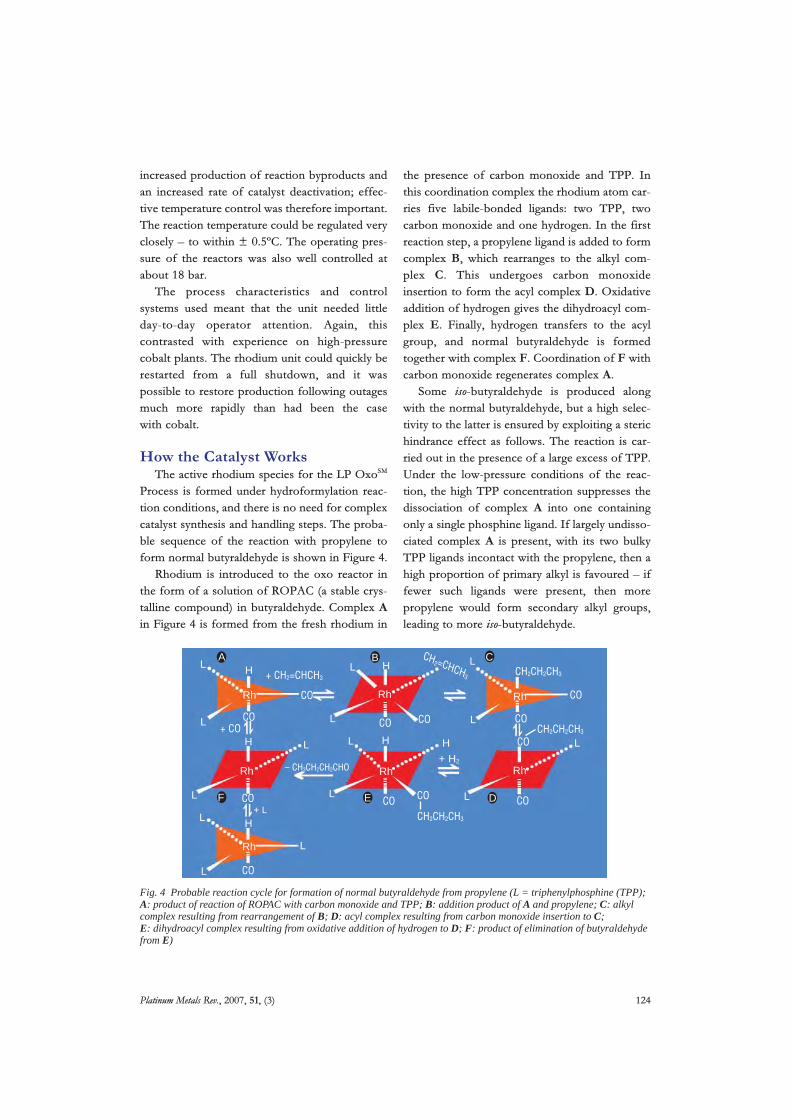
Process is formed under hydroformylation reac-tion conditions, and there is no need for complexcatalyst synthesis and handling steps. The proba-ble sequence of the reaction with propylene toform normal butyraldehyde is shown in Figure 4.
Rhodium is introduced to the oxo reactor inthe form of a solution of ROPAC (a stable crys-talline compound) in butyraldehyde. Complex Ain Figure 4 is formed from the fresh rhodium in
the presence of carbon monoxide and TPP. Inthis coordination complex the rhodium atom car-ries five labile-bonded ligands: two TPP, twocarbon monoxide and one hydrogen. In the firstreaction step, a propylene ligand is added to formcomplex B, which rearranges to the alkyl com-plex C. This undergoes carbon monoxideinsertion to form the acyl complex D. Oxidativeaddition of hydrogen gives the dihydroacyl com-plex E. Finally, hydrogen transfers to the acylgroup, and normal butyraldehyde is formedtogether with complex F. Coordination of F withcarbon monoxide regenerates complex A.
Some iso-butyraldehyde is produced alongwith the normal butyraldehyde, but a high selec-tivity to the latter is ensured by exploiting a sterichindrance effect as follows. The reaction is car-ried out in the presence of a large excess of TPP.Under the low-pressure conditions of the reac-tion, the high TPP concentration suppresses thedissociation of complex A into one containingonly a single phosphine ligand. If largely undisso-ciated complex A is present, with its two bulkyTPP ligands incontact with the propylene, then ahigh proportion of primary alkyl is favoured – iffewer such ligands were present, then morepropylene would form secondary alkyl groups,leading to more iso-butyraldehyde.
Platinum Metals Rev., 2007, 51, (3) 124
L
CO CO
CO
+ COCO
Rh
Rh
Rh
Rh
Rh
Rh
Rh
CO
CO CO CO CO
CO
CO
CO
L
L
L
L
L
L
L
+ L
L
L
L
L
L
L
L
H+ H2
H HCH2=CHCH3 CH2CH2CH3+ CH2=CHCH3
CH2CH2CH3
CH2CH2CH3
– CH3CH2CH2CHO
HH
H
A B C
DEF
Fig. 4 Probable reaction cycle for formation of normal butyraldehyde from propylene (L = triphenylphosphine (TPP);A: product of reaction of ROPAC with carbon monoxide and TPP; B: addition product of A and propylene; C: alkylcomplex resulting from rearrangement of B; D: acyl complex resulting from carbon monoxide insertion to C;E: dihydroacyl complex resulting from oxidative addition of hydrogen to D; F: product of elimination of butyraldehydefrom E)

Measures to Deal with CatalystDeactivation
The TPP-modified catalyst has a tendency todeactivate over time due to the formation from themonomeric rhodium species of rhodium clusters.This type of deactivation is termed ‘intrinsic’, todistinguish it from deactivation caused by an exter-nal source such as catalyst poisons present in thefeedstocks. Catalyst management models weredeveloped to help operators of the LP OxoSM
Process to optimise the economic return fromtheir catalyst charges, in recognition that intrinsicdeactivation had to be tolerated to some extent.For example, operating temperatures could not belowered to reduce catalyst deactivation if this alsoreduced catalyst productivity to uneconomic orunmanageable levels. Rhodium catalyst manage-ment guidelines from Union Carbide and DavyProcess Technology recommended operatingadjustments to compensate for deactivation, inresponse to accumulated operating data whichindicated the time evolution of catalyst activity.The guidelines were couched so as to optimise thebalance between reaction rate, selectivity to nor-mal butyraldehyde and catalyst stability. Whileoperators felt some obligation to comply with thelicensor’s recommendations, at least until perfor-mance warranties had been met, it was interestingto observe how the long-term catalyst operatingstrategies adopted by plant owners varied sowidely between plants, depending on specific cir-cumstances and preferences.
Plant operators observed rates of catalyst deac-tivation that meant that a rhodium catalyst chargewould typically last for about 18 to 24 monthsbefore its activity had declined to the point whenit would have to be discharged from the reactorand replaced by a fresh catalyst charge.
The earliest LP OxoSM plants contained verysimple equipment to concentrate the dischargedspent catalyst solution. The idea was that concen-trated catalyst, containing say 2000 ppm ofrhodium, would be shipped to Johnson Matthey inthe U.K., who would then recover the rhodium ina form suitable for reprocessing to ROPAC. Butthe logistics of actually reprocessing around 20 tonnes of concentrate for a typical plant were
somewhat daunting. There were concerns abouthandling and transporting such material in suchlarge quantities. With rhodium metal prices rising,the logistics might put the security of, say, U.S.$2million worth of rhodium at undue risk. Therewere also uncertainties about what other sub-stances might be present in the rhodiumconcentrate that could cause Johnson Mattheyprocessing problems. Although metals like ironand nickel that are usually found in commercialfeedstocks could be anticipated, would metal con-tamination compromise rhodium recovery? Therequirement for off-site rhodium recovery frombulk catalyst solution detracted from the eleganceof the LP OxoSM Process. Fortunately, by the timethe first licensed plants actually started operation,Union Carbide had proven a catalyst reactivationtechnique that would virtually obviate off-siterecovery.
Catalyst ReactivationBy the early 1980s, before any need had arisen
to resort to off-site rhodium recovery, UnionCarbide had developed a means to deal with theintrinsic deactivation – effectively by reversing it.This involved concentrating the spent catalyst andthen treating the rhodium present in the resultingresidue to convert it into a form capable of reacti-vation. The concentration process was carried outusing specialised equipment (a proprietary evapo-rator) under very precise conditions, includinghigh vacuum, designed to prevent catalyst damage.The overall process could conveniently be per-formed at the plant site, and required no chemicalreagents. It resulted in a ‘declustering’ of rhodiumto enable the restoration of activity once thetreated residue had been returned to a hydro-formylation environment. Eventually, all operatorseither added reactivation equipment to theirplants, or arranged to share facilities. Catalyst reac-tivation was incorporated into the standard designof all new plants, and a measure of lost elegancewas restored to the LP OxoSM Process!
The catalyst reactivation technique was used tocarry out repeated reactivations of what was essen-tially a single catalyst charge. This drasticallyreduced the need for off-site recovery, which was
Platinum Metals Rev., 2007, 51, (3) 125
normally deployed only on rhodium that could nolonger be reactivated economically. In that case,the recovery could be performed on residues typi-cally containing about 8000 ppm of rhodium, fourtimes the concentration initially envisaged, thusimproving the logistics and reducing the cost ofoff-site processing.
ConclusionThis article (Part I) has sought to demonstrate
the initial promise of the LP OxoSM Process,employing rhodium-based catalysis, in terms ofhigh availability, selectivity and productivity, lowenvironmental impact and low maintenance. PartII, to be published in a future issue of PlatinumMetals Review, will address subsequent key improve-ments to the process, and its use in non-propyleneapplications.
LP OxoSM is a service mark of The Dow Chemical Company.
References1 Davy Process Technology Ltd.:
http://www.davyprotech.com/
2 The Dow Chemical Company: http://www.dow.com/3 Union Carbide Corporation:
http://www.unioncarbide.com/4 R. L. Pruett and J. A. Smith, Union Carbide Corporation,
‘Hydroformylation Process’, U.S. Patent 3,527,809; 19705 G. Wilkinson, Johnson Matthey, ‘Improvements in
Catalytic Hydrogenation or Hydroformylation’, BritishPatent 1,219,763; 1971
6 M. L. H. Green and W. P. Griffith, Platinum Metals Rev.,1998, 42, (4), 168
7 W. P. Griffith, Platinum Metals Rev., 2007, 51, (3), 1508 F. J. Smith, Platinum Metals Rev., 1975, 19, (3), 939 Production estimates provided by RXN Petrochemical
Consulting Inc.: http://rxnpetrochem.com/page4.html
Further Reading‘Low-pressure oxo process yields a better product mix’,Chem. Eng. (New York), 5th December, 1977, 84, (26), 110;marking the award of the 1977 Kirkpatrick ChemicalEngineering Achievement Award to the winners: UnionCarbide Corporation, Davy Powergas Ltd., and JohnsonMatthey & Co. Ltd.
J. L. Stewart, ‘LP OxoSM process – a success story’,Indications, Winter 1982/83; the international journal ofDavy McKee
Platinum Metals Rev., 2007, 51, (3) 126
The AuthorsRichard Tudor is a chartered chemicalengineer. He has played a leading part inDavy Process Technology’s oxo licensingactivities for over thirty years, firstly asProcess Manager, and then as BusinessManager after a period as LicensingManager. As a Vice President of sales andmarketing, he now has overall responsibilityfor the oxo business.
Mike Ashley spent many years with JohnBrown, involved with process technology andbusiness development, before joining DavyProcess Technology. He is now concernedwith business analysis, technologyacquisition, marketing, website developmentand all aspects of public relations.

www.technology.matthey.comJOHNSON MATTHEY TECHNOLOGY REVIEW
http://dx.doi.org/10.1595/205651314X684726 Johnson Matthey Technol. Rev., 2014, 58, (4), 217–220
217 © 2014 Johnson Matthey
40 Years of Cleaner Air: The Evolution of the Autocatalyst Autocatalysts have prevented billions of tonnes of pollution from entering the atmosphere and offer solutions to current concerns about urban vehicle pollution
By Chris MorganJohnson Matthey Emission Control Technologies, Orchard Road, Royston, Hertfordshire, SG8 5HE, UK
Email: [email protected]
The 40th anniversary of the manufacture of the world’s fi rst commercial batch of autocatalysts for passenger cars at Johnson Matthey Plc’s site in Royston, UK, was marked in May 2014. Despite the enormous progress made in reducing the emission of pollutants from vehicles since the 1970s, there has also been considerable recent discussion about the levels of nitrogen oxides (NOx), especially nitrogen dioxide (NO2), and particulate matter (PM) in today’s urban environment. This article describes the evolution of catalyst technologies over the last forty years and the next generation of products which will enable further advances in air quality.
Initial Breakthroughs
From the 1940s onwards large cities, particularly in the USA and around Tokyo, were experiencing increasing levels of air pollution. In the 1950s work in California proved that photochemical smog formed from reactions between NOx and hydrocarbons (HCs) (1) and that internal combustion engine exhaust was a major source of such pollution (2). Clean Air Acts were passed in the UK and in the USA, and from 1968 all new passenger cars in the USA had to meet exhaust gas emissions standards. Initially these were achieved through better engine tuning, but an amendment requiring a further
90% reduction in emissions by 1975 forced the use of catalytic exhaust gas aftertreatment systems.
Johnson Matthey had been conducting research in the area since 1969, and in 1971 fi led a patent for a rhodium-promoted platinum catalyst (3). This was used in a ‘two-way’ device, designed to remove the carbon monoxide (CO) and HC emissions caused by incomplete combustion of the fuel. Exhaust gas recirculation was used to control NOx emissions. Proof of durability was a critical step in the acceptance of the new technology. In 1972 Johnson Matthey demonstrated to the US authorities that a catalyst system still met the 1975 emissions standards after 26,500 miles of driving on a Chrysler Avenger (Figure 1) (4), helping to maintain the timetable for introduction of the legislation. In parallel, the introductions of lead-free gasoline and ceramic honeycomb materials that could support high temperature catalytic processes were also essential.
To achieve lower NOx emissions a dual-bed catalytic converter was developed (4). The engine was run rich, i.e. with an excess of fuel to generate reducing conditions, and NOx was reduced to nitrogen over the fi rst catalyst. Secondary air was introduced into the exhaust to generate net oxidising conditions before the second catalyst, which was designed to oxidise CO and HC to CO2 and water. While this system was effective it compromised fuel economy. The development of oxygen sensors in the late 1970s allowed the design of closed loop engine management systems which could accurately control the air to fuel ratio (AFR). This allowed the exhaust gas composition to be balanced at the optimum point for ‘three-way’ conversion: simultaneous oxidation of CO and HC and reduction of NOx over a single catalyst. Such three-way catalysts

218 © 2014 Johnson Matthey
http://dx.doi.org/10.1595/205651314X684636 Johnson Matthey Technol. Rev., 2014, 58, (4)
(TWCs) were essential to meet another tightening of US emission limits effective from 1981.
Developing Today’s Catalysts
The early TWC designs are recognisable as the precursors to today’s gasoline autocatalysts. There have since been major improvements in coating design, application of platinum group metals (pgms), thermal stability of raw materials and properties of the cerium-containing oxygen storage materials. Along with advances in engines and substrates, these have enabled increasingly stringent emissions limits and durability targets to be met on current gasoline vehicles around the world, whilst using substantially less pgms.
The emissions story in the US and Japan was focused primarily on gasoline vehicles, but in Europe, where passenger car emissions legislation was introduced in 1993, diesel engines had a signifi cant market share. Heavy duty applications also predominantly used diesel engines. Diesel oxidation catalysts (DOCs) were effective in removing CO and HC emissions, but soot became a signifi cant concern, especially in local low emission zones. In 1990 Johnson Matthey patented the use of NO2 to reduce the combustion temperature of diesel soot (5). This technology was launched as the continuously regenerating trap (CRT®) in 1995, comprising a DOC to oxidise CO and HC and form NO2 upstream of a cordierite particulate fi lter (6). This achieved much success as a retrofi t device to control
emissions from local bus and truck fl eets, and was later incorporated onto new vehicles. PM limits for diesel passenger cars did not require the fi tment of fi lters until the introduction of Euro 4 legislation in 2005.
A limitation of the CRT® design was that each NO2 molecule could only react once with the carbonaceous soot, requiring engines to be run at a high NOx:PM ratio. Incorporating pgm-containing washcoat into the fi lter walls, enabling ‘used’ NO molecules to be reoxidised to NO2 in situ, allowed much more effi cient fi lter regeneration at lower NOx:PM ratios. This was the basis of the catalysed soot fi lter (CSF) (7), now common in light and heavy duty diesel applications.
The Future of Cleaner Air
Compared to those from 1974, today’s vehicles have much cleaner and more effi cient combustion processes, improved fuel injection system design and sophisticated engine management systems and sensing technologies. In conjunction with advanced catalyst technologies a modern passenger car typically emits one-hundredth as much pollution as one from ca. 1960. However, the impact of air quality on human health, particularly in urban environments, is high on the political agenda. Many European cities are breaching European Union limits on NO2, leading to renewed debate about local measures to reduce pollution (8). European real world driving emissions (RDE) legislation is being prepared, with the aim of ensuring that vehicle pollution is controlled over a wide
Fig. 1. (a) The Chrysler Avenger test vehicle; and (b) exhaust emissions obtained using the 1975 control system over 26,500 miles testing. (o = emissions at 26,500 miles before servicing of the vehicle, x = emissions at 26,500 miles after normal servicing of the engine, during which process the catalyst was not touched) (4)
(a) (b)

219 © 2014 Johnson Matthey
http://dx.doi.org/10.1595/205651314X684636 Johnson Matthey Technol. Rev., 2014, 58, (4)
range of driving styles and ambient conditions, not just over the specifi ed drive cycles. Meanwhile pollution is a major issue in many Asian cities, with, for example, Beijing considering the introduction of increasingly stringent emission limits.
The introduction of diesel particulate fi lters on light duty diesel (LDD) and heavy duty diesel (HDD) vehicles has been an important step towards addressing these concerns, supported by future legislation to control the number of particulates emitted (and not just their total mass) from gasoline direct injection engines in Europe and similar legislation expected for non-road mobile machinery. Selective catalytic reduction (SCR) is already a widely used technology to control NOx emissions from HDD applications in developed markets. Furthermore Euro 6 passenger car legislation, which came into effect in September 2014, more than halved the permitted NOx emissions from compression ignition engines, necessitating the introduction of specifi c NOx control technologies on almost all new European diesel passenger cars.
There are currently two competing technologies for diesel NOx control: SCR and NOx adsorber catalysts (NACs) (9), each with advantages and disadvantages. SCR systems, based on copper, iron or vanadium materials, reduce NOx to nitrogen through reactions with stored ammonia. High NOx conversion rates can be achieved and the reaction occurs under a standard diesel AFR, maintaining fuel economy. However, the ammonia is derived from the decomposition of urea solution injected into the exhaust gas upstream of the SCR catalyst. This requires an additional storage tank, urea injection and control system, the cost and space requirements of which can be prohibitive for smaller vehicles. The urea decomposition threshold temperature of ca. 180ºC, limits the effectiveness of SCR systems in extended low temperature regimes such as low speed city driving in winter. There are also concerns about the release of excess ammonia into the atmosphere, leading to the development of additional ammonia slip catalysts (ASCs).
NACs trap NOx emissions during normal operation, typically by oxidation over a pgm and storage as nitrate on an alkaline earth such as barium. As the NAC has a fi nite NOx storage capacity, it is necessary to periodically regenerate the catalyst. This is achieved by running the engine rich for a few seconds to increase the concentrations of reductants including CO, HC and hydrogen in the exhaust gas. Under the rich conditions the nitrate decomposes and the
released NOx species are converted to nitrogen through reaction with the exhaust gas reductants over a second catalytic component, typically supported rhodium. The periodic requirement to run the engine rich adds to the complexity of the powertrain design and worsens fuel economy, which is undesirable given legislative targets to reduce CO2 emissions/improve fuel economy. The additional cost of pgms can be a concern for larger vehicles. Furthermore there is a temperature window where NACs operate effectively: at higher temperatures the storage mechanism is less stable and at lower temperatures the NOx release and reduction reactions are less effective.
To address NOx control for RDE on diesel passenger cars a likely solution is a combination of NAC and SCR systems, harnessing the strengths of each technology. An upstream NAC will store NOx emissions at low temperatures when the SCR system is less effective. The NAC will also act as an oxidation catalyst to convert HC and CO emissions. A downstream SCR will provide NOx control under higher speed, higher temperature conditions, also enabling extended lean operation for improved fuel economy. Optimisation of such systems is taking place, with focus on matching the operating temperature windows of the NAC and SCR components.
As engines become increasingly fuel effi cient less waste heat enters the exhaust. This is a critical concern for the aftertreatment system as it leads to lower catalyst operating temperatures. A common diesel catalyst architecture comprises a DOC followed by CSF, urea injection and SCR. Due to the thermal mass of the CSF (required to withstand uncontrolled soot regeneration) and heat losses from the exhaust pipe in the urea mixing zone in front of the SCR, it can take many minutes of city driving before the SCR warms up suffi ciently to provide high levels of conversion effi ciency. An elegant solution is to integrate the SCR coating onto the particulate fi lter (10), thus enabling the SCR coating to heat up and become active more quickly, whilst also improving the compactness of the system (Figure 2). Such SCR coated on fi lter (SCRF®) technologies are now in series production – another world fi rst for Johnson Matthey, Royston. Design challenges include the incorporation of signifi cantly higher coating loadings onto a fi lter than were required for CSF, leading to a requirement for high porosity fi lter substrates and optimisation of the fi ltration effi ciency and pressure drop characteristics.

220 © 2014 Johnson Matthey
http://dx.doi.org/10.1595/205651314X684636 Johnson Matthey Technol. Rev., 2014, 58, (4)
Conclusions
Since the development of the fi rst catalytic converters there have been many advances in powertrain, substrate and catalyst technologies over the last forty years. Emissions control systems are now required in countries across the world and they have prevented billions of tonnes of pollutants from entering the atmosphere. However, NOx and PM pollution continues to affect human health, particularly in urban environments. The introduction of new technologies to control diesel NOx emissions, alongside the more widespread fi tment of particulate fi lters, will lead to further improvements in air quality.
References
1. A. J. Haagen-Smit and M. M. Fox, Ind. Eng. Chem., 1956, 48, (9), 1484
2. L. H. Rogers, J. Chem. Educ., 1958, 35, (6), 310
3. G. J. K. Acres, Johnson, Matthey & Co, Ltd, ‘Improvements in and Relating to Catalysis’, British Patent 1,390,182; 1971
4. G. J. K. Acres and B. J. Cooper, Platinum Metals Rev., 1972, 16, (3), 74
5. B. J. Cooper, H. J. Jung and J. E. Thoss, Johnson Matthey, Inc, ‘Treatment of Diesel Exhaust Gases’, US Patent 4,902,487; 1990
6. P. N. Hawker, Platinum Metals Rev., 1995, 39, (1), 2
7. M. V. Twigg and P. R. Phillips, Platinum Metals Rev., 2009, 53, (1), 27
8. ‘Environment: Commission Takes Action Against UK for Persistent Air Pollution Problems’, European Commission, IP/14/154, Brussels, Belgium, 20th February, 2014
9. T. Johnson, Platinum Metals Rev., 2008, 52, (1), 23
10. A. P. Walker, ‘Challenges and Solutions in Diesel Emission Control’, Catalysis Club of Philadelphia 2008 Spring Symposium, USA, 22nd May, 2008
Fig. 2. Schematic demonstrating how the SCRF® improves system compactness and an example of how, over the European drive cycle, it warms up more quickly than an SCR downstream of a CSF (due to its closer proximity to the engine) enabling earlier NOx conversion
NO
x em
issi
ons,
g
2.5
2
1.5
1
0.5
0 200 400 600 800 1000 1200Time, s
Engine out NOx
Tailpipe NOx – SCR
Tailpipe NOx – SCRF®
SCR
inle
t tem
pera
ture
, ºC 400
300
200
100
0 200 400 600 800 1000 1200Time, s
DOC
DOC
CSF SCR
SCRF®
Inlet temperature – SCRF®
Inlet temperature – SCR
The Author
Chris Morgan is Technology Director at Johnson Matthey’s European Emission Control Technologies business, responsible for the development and scale-up of autocatalyst coatings for light duty gasoline and diesel applications. Chris previously managed the Gasoline Product Development team, developing new families of three-way catalysts and leading Johnson Matthey’s early work on coatings for gasoline particulate fi lters. He joined Johnson Matthey in 1997, after completing a DPhil at the University of Oxford, UK, on high temperature ceramic superconductors.

•Platinum Metals Rev., 2013, 57, (4), 259–271•
259 © 2013 Johnson Matthey
The Role of Platinum in Proton Exchange Membrane Fuel CellsEvaluation of platinum’s unique properties for use in both the anode and cathode of a proton exchange membrane fuel cell
http://dx.doi.org/10.1595/147106713X671222 http://www.platinummetalsreview.com/
By Oliver T. Holton* and Joseph W. Stevenson**
Johnson Matthey, Orchard Road, Royston, Hertfordshire SG8 5HE, UK
Email: *[email protected]; **[email protected]
Proton exchange membrane fuel cells (PEMFCs)
dominate the transportation fuel cell market and
platinum (Pt) is the catalyst material used for both anode
and cathode. This review sets out the fundamentals of
activity, selectivity, stability and poisoning resistance
which make Pt or its alloys the best available materials
to use in this application. It is clear that Pt is the
only element which can meet the requirements for
performance while avoiding slow reaction kinetics,
proton exchange membrane (PEM) system degradation
due to hydrogen peroxide (H2O2) formation and catalyst
degradation due to metal leaching. Some of the means
by which the performance of Pt can be enhanced are
also discussed.
IntroductionA PEMFC is a device that electrochemically reacts
hydrogen (H2) with oxygen (O2) to produce electricity
with water as the only by-product. Fuel cells offer the
capability to provide clean energy transportation with
zero tailpipe carbon dioxide (CO2) emissions. Even
where their fuel must be sourced from fossil fuels,
the high effi ciency of fuel cells relative to internal
combustion engines still offers the potential for
reduced well to wheel CO2 emissions (1).
PEMFCs have dominated the transportation fuel
cell market and will do so for the foreseeable future
(2) for several reasons. They have a unique set of
advantages for use in vehicles: a suffi ciently low
working temperature (80ºC) that they can be started
up quickly; a good energy density versus other fuel
cell types; robust and relatively simple mechanics; the
ability to run on pure hydrogen, therefore emitting no
CO2; and the ability to use ambient air as the oxidant.
PEMFCs currently use Pt as the catalyst both at
the cathode and at the anode, for reasons which
will be described in this paper. The most recent
US Department of Energy analysis (3) indicates
that Pt would be around 17% of the total cost of
an 80 kW PEMFC system using 2012 technology at

http://dx.doi.org/10.1595/147106713X671222 •Platinum Metals Rev., 2013, 57, (4)•
260 © 2013 Johnson Matthey
mass production scale. Naturally there is interest in
developing substitute catalysts based on cheaper
metals, although any other catalyst developed would
need to exceed Pt in terms of performance against
total system cost.
This review focuses on the fundamentals that are
required for an idealised PEMFC electrode material
and evaluates the performance of pure Pt compared
to other pure metals. It fi nishes with a discussion of
alternatives to pure Pt.
The Role of the Catalyst in a Proton Exchange Membrane Fuel CellFigure 1 shows how a PEMFC works. Hydrogen gas
is fed to the anode where it adsorbs onto the catalyst
surface. The adsorbed hydrogen atoms each lose an
electron (e–) and are released from the metal surface
as protons (H+). The electrons fl ow to the cathode as
current through an external circuit and the protons
fl ow across the PEM towards the cathode. Air is fed to
the cathode and oxygen is adsorbed onto the catalyst
surface. This bound oxygen is subsequently protonated
by incoming H+ and reduced by incoming electrons to
produce water which is then released from the catalyst
surface. This water is forced to exit the fuel cell by the
hydrophobic nature of the surrounding media.
Pt is used as the catalyst for both the hydrogen
oxidation reaction (HOR) occurring at the anode and
the oxygen reduction reaction (ORR) at the cathode.
Usually, the Pt catalyst takes the form of small particles
on the surface of somewhat larger carbon particles
that act as a support.
Anode Processes Hydrogen fl ows into the fuel cell and reaches the Pt
anode where the HOR takes place. Here the hydrogen
adsorbs onto the surface of the Pt electrode, breaking
the hydrogen–hydrogen bond to give adsorbed atomic
hydrogen (H*) (4), Equation (i):
½ H2 + * H* (i)
(where * denotes a surface site).
Subsequent loss of an electron from each adsorbed
hydrogen leads to hydrogen leaving the surface as
protons (H+), Equation (ii):
H* H+ + * + e– (ii)
In a PEMFC, the kinetics of the HOR on a Pt
electrode are very fast. Voltage losses are vanishingly
small even for very low Pt loadings (less than 5 mV
loss at Pt anode loadings of 0.05 mg cm–2) (5). As the
HOR is fast, the main focus of catalyst improvement
has always been on the cathode process.
Cathode Processes The ORR that occurs at the cathode has a more
complicated mechanism and it is well known for
its sluggish kinetics (6, 7). The ORR is the major
challenge for PEMFCs because the catalyst material
must be stable under the extremely corrosive
Oxygen
Electron fl ow
Hydrogen
Hydrogen ions
Excess hydrogenAnode Electrolyte Cathode
Water
Fig. 1. A schematic of a proton exchange membrane fuel cell (Copyright Johnson Matthey)

http://dx.doi.org/10.1595/147106713X671222 •Platinum Metals Rev., 2013, 57, (4)•
261 © 2013 Johnson Matthey
conditions at a fuel cell cathode yet chemically
active enough to be able to activate O2. In addition
it must be noble enough for facile release of product
water from the catalyst surface in order to free up
catalytic sites once the reaction is complete. Due to
the diffi culties of the ORR, the cathode requires a
higher Pt loading, typically more than several times
that of the anode (8). The ORR at the cathode is the
source of more than half of the voltage loss for a
PEMFC system (9).
There are two pathways by which ORR can occur in
acidic media (4). The fi rst mechanism is the preferred
dissociative pathway and follows a concerted ‘four
electron’ transfer process leading to direct formation
of water. First O2 adsorbs to the metal surface and
the oxygen–oxygen bond breaks to give adsorbed
oxygen atoms (O*), Equation (iii):
½ O2 + * O* (iii)
These single oxygen atoms are then protonated by
the incoming fl ow of H+ across the PEM and reduced
by incoming fl ow of electrons to give surface bound
hydroxyl (OH*) (10) groups, Equation (iv):
O* + H+ + e– OH* (iv)
The surface bound OH* is then further reduced and
protonated to give water which then leaves the metal
surface, Equation (v):
OH* + H+ + e– H2O + * (v)
The alternative pathway is an associative mechanism
where the O=O bond does not break upon O2 adsorption
onto the metal surface (Equations (vi) to (vii)) (11):
O2 + * O2* (vi)
O2* + H+ + e– HO2* (vii)
This alternative ‘two electron’ route is observed
to produce H2O2. The details of the mechanism are
unclear, but the reaction may proceed as follows
(11) (Equation (viii)):
HO2* + H+ + e– H2O2* (viii)
The H2O2 may react further or desorb (Equation (ix)):
H2O2* H2O2 + * (ix)
Figure 2 shows a simplifi ed representation of
possible associative and dissociative mechanisms (4).
Generation of H2O2 in a PEMFC is highly undesirable
as it diffuses into the PEM and results in radical
oxidative degradation of the membrane (12). Poor
ORR catalysts produce signifi cant amounts of H2O2
through associative ORR (13) whereas a good catalyst
should produce little or no H2O2.
Although the kinetics of HOR and ORR are different,
the overall trend in reaction rates on different metal
electrodes is similar for both.
Required Characteristics of an Effective Proton Exchange Membrane Fuel Cell CatalystThere are four main characteristics that are essential
for an effective PEMFC catalyst:
(a) Activity – to be able to adsorb the reactant strongly
enough to facilitate a reaction but not so strongly
that the catalyst becomes blocked by the reactant
or products.
(b) Selectivity – to make the desired product
and minimise the production of undesirable
intermediates and side products.
(c) Stability – to withstand the operating environment
in a fuel cell, including strong oxidants, reactive
radicals, an acidic environment and high and
rapidly fl uctuating temperatures, all whilst under
an applied voltage.
(d) Poisoning resistance – to be resistant to poisoning
by impurities likely to be found in the fuel cell
itself and in the feed gases.
The following sections will discuss the performance
of pure Pt compared to other pure metals with respect
to these characteristics.
ActivityFor heterogeneous catalysis on a metal surface, the
catalyst must adsorb species with suffi cient strength
O2
dissociative
associative
O2* H2O2*
H2O2
H2O
Fig. 2. Generation of hydrogen peroxide through associative oxygen reduction reaction (4)
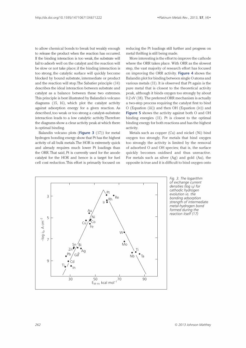
http://dx.doi.org/10.1595/147106713X671222 •Platinum Metals Rev., 2013, 57, (4)•
262 © 2013 Johnson Matthey
to allow chemical bonds to break but weakly enough
to release the product when the reaction has occurred.
If the binding interaction is too weak, the substrate will
fail to adsorb well on the catalyst and the reaction will
be slow or not take place; if the binding interaction is
too strong, the catalytic surface will quickly become
blocked by bound substrate, intermediate or product
and the reaction will stop. The Sabatier principle (14)
describes the ideal interaction between substrate and
catalyst as a balance between these two extremes.
This principle is best illustrated by Balandin’s volcano
diagrams (15, 16), which plot the catalyst activity
against adsorption energy for a given reaction. As
described, too weak or too strong a catalyst–substrate
interaction leads to a low catalytic activity. Therefore
the diagrams show a clear activity peak at which there
is optimal binding.
Balandin volcano plots (Figure 3 (17)) for metal
hydrogen bonding energy show that Pt has the highest
activity of all bulk metals. The HOR is extremely quick
and already requires much lower Pt loadings than
the ORR. That said, Pt is currently used for the anode
catalyst for the HOR and hence is a target for fuel
cell cost reduction. This effort is primarily focused on
reducing the Pt loadings still further and progress on
metal thrifting is still being made.
More interesting is the effort to improve the cathode
where the ORR takes place. With ORR as the slowest
step, the vast majority of research effort has focused
on improving the ORR activity. Figure 4 shows the
Balandin plot for binding between single O atoms and
various metals (11). It is observed that Pt again is the
pure metal that is closest to the theoretical activity
peak, although it binds oxygen too strongly by about
0.2 eV (18). The preferred ORR mechanism is actually
a two-step process requiring the catalyst fi rst to bind
O (Equation (iii)) and then OH (Equation (iv)) and
Figure 5 shows the activity against both O and OH
binding energies (11). Pt is closest to the optimal
binding energy for both reactions and has the highest
activity.
Metals such as copper (Cu) and nickel (Ni) bind
oxygen too strongly. For metals that bind oxygen
too strongly the activity is limited by the removal
of adsorbed O and OH species; that is, the surface
quickly becomes oxidised and thus unreactive.
For metals such as silver (Ag) and gold (Au), the
opposite is true and it is diffi cult to bind oxygen onto
Au
InTi
Cd
GaPbAgZn
Sn Bi
FeCu Co
Ni
PtReRh
Ir
W
MoTi
Nb Ta
30 50 70 90EM–H, kcal mol–1
3
5
7
9
–log
i 0, A
cm
–2
Fig. 3. The logarithm of exchange current densities (log i0) for cathodic hydrogen evolution vs. the bonding adsorption strength of intermediate metal-hydrogen bond formed during the reaction itself (17)

http://dx.doi.org/10.1595/147106713X671222 •Platinum Metals Rev., 2013, 57, (4)•
263 © 2013 Johnson Matthey
Ru
O binding too strong
Pt
Pd
–3 –2 –1 0 1 2 3 4
O binding too weak
0.0
–0.5
–1.0
–1.5
–2.0
–2.5
Act
ivity
∆EO, eV
FeW
Mo
Co
Ni
RhCu
Ir Ag
Au
Fig. 4. Trends in oxygen reduction activity plotted as a function of the oxygen binding energy (Reprinted with permission from (11). Copyright 2004 American Chemical Society)
–0.5
–1.0
–1.5
–2.0
–2.5
–3.0
–3.5
–4.0
–4.5
–5.0
Ag
Au
Pt
Pd
IrCu
RhNi
Ru
Co
Fe
Mo
W
Activity
–1.5 –1 –0.5 0 0.5 1 1.5 2
∆EOH, eV
3
2
1
0
–1
–2
∆E 0
, eV
Fig. 5. Trends in oxygen reduction activity plotted as a function of both the oxygen and the hydroxyl group binding energy (Reprinted with permission from (11). Copyright 2004 American Chemical Society)

http://dx.doi.org/10.1595/147106713X671222 •Platinum Metals Rev., 2013, 57, (4)•
264 © 2013 Johnson Matthey
the metal surface. For these metals the rate is limited
by the dissociation of O2 or the transfer of electrons
and protons to adsorbed oxygen species (12).
SelectivityThe second requirement is selectivity. The catalyst must
progress the reaction to make the desired product
whilst minimising the production of undesirable
intermediates and side products. The HOR has only
one mechanism and can produce only H+ and e–.
As such, selectivity is not an issue in the context of
the HOR.
At the cathode, the ORR reaction can follow one of
two pathways and the pathway is determined by the
selectivity of the catalyst in the fi rst step (adsorption
of O2). The discussion of activity above has focused on
the desired, dissociative four electron ORR mechanism
to produce water (Equations (iii) to (v)). However, it
is important to discuss the alternative two electron
reaction associative mechanism which produces
H2O2. Catalyst materials must be chosen to minimise
the undesired associative mechanism as the presence
of free H2O2 within the cell environment is highly
damaging (12).
The associative mechanism which leads to H2O2
starts when O2 is adsorbed on a metal surface without
the O=O bond being broken. On a Pt surface however,
the O=O bond is usually broken upon adsorption.
The reaction therefore proceeds almost exclusively
according to the desired dissociative mechanism.
Since there is no adsorbed O2 on the Pt surface, H2O2
cannot be formed (4).
The amount of H2O2 produced on various metal
catalyst surfaces has been investigated using scanning
electrochemical microscopy and calculation of the
total number of electrons transferred (n) (Figure 6
Fig. 6. Number of electrons transferred (n) during oxygen reduction reaction at: (a) mercury, gold, silver, copper and Au60Cu40; and (b) platinum, palladium and Pd80Co20 as a function of applied potential in an oxygen saturated 0.5 M sulfuric acid solution (Reprinted with permission from (19). Copyright 2009 American Chemical Society)
Cu4.0
3.8
3.6
3.4
3.2
3.0
2.8
2.6
2.4
2.2
2.00.3 0.2 0.1 0.0 –0.1 –0.2 –0.3 –0.4
Esubs (V) vs. RHE
Au60Cu40
Ag
AuHg
n
0.8 0.7 0.6 0.5 0.4 0.3
4.0
3.8
3.6
3.4
3.2
3.0
2.8
2.6
2.4
2.2
2.0
n
Esubs (V) vs. RHE
PtPd80Co20
Pd
(a)
(b)

http://dx.doi.org/10.1595/147106713X671222 •Platinum Metals Rev., 2013, 57, (4)•
265 © 2013 Johnson Matthey
(19)). A result of n = 2 signifi es only H2O2 production,
with n = 4 showing no H2O2 (only H2O) formation.
From the study, mercury (Hg) shows the lowest value
of n at close to 2, whereas Pt and Pd80Co20 show the
highest values n at almost 4. The other materials tested
show intermediate n values which vary as a function
of potential.
Thus it may be concluded that Pt is the most selective
metal towards the desired ORR at the cathode as it is
nearly 100% selective for the dissociative mechanism
over a broad potential range.
Stability For any metal to be suitable as a fuel cell electrocatalyst,
it must not only have suitable catalytic activity and
selectivity, but it must also be able to withstand the
harsh chemical environment within a fuel cell. The
presence of strong oxidants, reactive radicals, low pH,
high temperatures and rapid potential fl uctuations,
especially on the cathode, rules out the use of most
transition metals in their pure forms. The main
problem is that very few metals are suffi ciently noble
to avoid dissolution at the low pHs and high electrode
potentials experienced at the fuel cell cathode. Those
that are stable tend to be covered with oxide fi lms
that inhibit dissolution, but also the ORR. Lack of short
term stability is most immediately obvious as a loss in
kinetic activity, but long term stability of the catalyst is
key to overall system durability.
Pourbaix diagrams (20) show the thermodynamic
stability of different metals under different applied
voltages and pH conditions. These diagrams map out
the most thermodynamically stable species in each
domain on a plot of pH versus applied voltage for a
particular element. When conditions stray into areas
of the diagram that represent a change of the most
stable elemental metallic form to an oxide or different
oxidation state, then corrosion or passivation –
formation of a ‘protective’ layer on the surface of the
given metal – can then occur. As an example, the
Pourbaix diagram for cobalt (Co) is Figure 7 (21, 22).
It can be seen that the low pH conditions in a fuel
cell will corrode Co; the immunity domain for Co (in
plain white) only exists below around –0.5 V in acidic
conditions. This has been observed experimentally;
pure Co reacts in acidic media to form soluble
products and Co has been shown to rapidly leach out
of Co-based electrode materials (23, 24).
Figure 8 shows Pourbaix diagrams for different
metals listed in order of nobility (unreactivity) (21, 22).
It can be seen that noble metals such as Au, iridium
(Ir) and Pt are quite stable in the fuel cell environment
(high cell potential, low pH), whereas metals such as
Ni, Co and iron (Fe) are predicted to dissolve. This
is indeed what is experimentally observed; these
transition metals are electrochemically soluble at
a potential range between 0.3 V and 1 V in low pH
conditions (25).
The handful of other acid-stable metals have lower
activities and selectivities compared to Pt. Therefore
the acid/base stability of Pt under typical PEMFC
operating conditions, in combination with its activity
and selectivity, renders it the only suitable pure metal
to be used in the PEMFC application (26).
Poisoning ResistanceA good catalyst must be resistant to poisoning by
impurities likely to be found in the fuel cell itself and
in the feed gases. Impurities in both the hydrogen and
the air streams may have a negative impact upon the
workings of a PEMFC. All catalysts are susceptible to
poisoning but there are so many different poisons and
poisoning mechanisms that it is very diffi cult to make
any meaningful absolute ranking (27).
Most problematic for Pt in PEMFC applications are
sulfur species (28) and carbon monoxide (CO) (29).
Pt is neither the least nor the most sensitive metal to
these or other poisons. In fuel cell applications, as
Fig. 7. The Pourbaix diagram for cobalt (With kind permission from Springer Science+Business Media (21, 22))
Corrosion yielding soluble productsCorrosion yielding gaseous productsCorrosion yielding soluble and gaseous productsPassivation by a fi lm of oxide or hydroxidePassivation by a fi lm of hydrideImmunity
2
1
0
–1
–2
E H, V
0 7 14pH

http://dx.doi.org/10.1595/147106713X671222 •Platinum Metals Rev., 2013, 57, (4)•
266 © 2013 Johnson Matthey
1. G
old
2. Ir
idiu
m
3. P
latin
um
4. R
hodi
um
5. R
uthe
nium
6.
Pal
ladi
um
7. M
ercu
ry
8. S
ilver
9.
Osm
ium
10
. Sel
eniu
m
11. T
ellu
rium
12
. Pol
oniu
m
13. C
oppe
r 14
. Tec
hnet
ium
15. B
ism
uth
16. A
ntim
ony
17. A
rsen
ic
18. C
arbo
n 19
. Lea
d 20
. Rhe
nium
21
. Nic
kel
22. C
obal
t 23
. Tha
lium
24
. Cad
miu
m
25. I
ron
26. T
in
27. M
olyb
denu
m
28. T
ungs
ten
2 1 0 –1 –2 2 1 0 –1 –2 2 1 0 –1 –2 2 1 0 –1 –2
EH, V EH, V EH, V EH, V
Fig. 8. The Pourbaix diagrams for different elements listed in order of nobility (With kind permission from Springer Science+Business Media (21, 22)). For key to this fi gure see Figure 7

http://dx.doi.org/10.1595/147106713X671222 •Platinum Metals Rev., 2013, 57, (4)•
267 © 2013 Johnson Matthey
in other catalytic applications for Pt, there are two
methods of protection: keeping the poisons out of the
system and alloying the Pt with other metals to reduce
susceptibility to poisoning. The nature of impurities in
the hydrogen fuel stream depends on the source of
the hydrogen (29). Strict quality specifi cations have
been agreed for hydrogen intended for use in fuel cell
vehicles (30). However improved tolerance to poisons
will still be advantageous to avoid any sub-standard
batches of hydrogen causing irreversible damage to
PEMFCs.
For complicated systems such as alloys, there is
no simple way to predict in advance the precise
susceptibility to sulfur poisoning (31). Many
fundamental studies on the interaction of sulfur
species with elemental catalysts have been undertaken
(32–41). Unsupported or supported Pt-based alloy
catalysts have been demonstrated to exhibit high
tolerance to CO poisoning. These include binary,
ternary and quaternary Pt alloys, Pt-based metal oxide
catalysts (42–44), Pt-based composites and organic
metal complexes (45, 46). More information on the
development of high-performance and cost-effective
CO-tolerant anode electrocatalysts for PEMFCs can
be found in several comprehensive review articles
(47–52).
Alternatives to Pure PlatinumThere is a limited amount of interest in improving
the HOR (53); as this review has discussed the major
focus has always been on improving the ORR. While
Pt is the best pure metal in terms of activity, selectivity
and stability for both anode and cathode in a PEMFC,
it does not sit at the peak of the Balandin volcano
plot for the ORR. The perfect catalyst according to
the Sabatier principle would have slightly different
electronic properties. Therefore a lot of research
focuses on fi ne tuning the electronic properties of Pt
in order to optimise the resulting catalyst material.
Approaches currently used to improve Pt activity are:
(a) Alloying with one or more other metals;
(b) Layering Pt on or just below the surface of another
metal;
(c) A core–shell approach where a core of cheaper
metal is coated with Pt;
(d) Alloying Pt followed by dealloying such that the
fi nished Pt lattice structure retains some of the
original structural strain associated with alloying.
The objective of all of these approaches is to modify
the electronic properties of Pt to bring the adsorption
energy for the O and OH reduction reactions closer
to the Sabatier ideal. The improved activity of these
modifi ed Pt structures has been attributed to many
factors including changes in the number of nearest
Pt neighbours, average Pt–Pt distance and Pt 5d band
vacancy (54, 55).
In addition, various ‘novel technologies’ have been
used to support and fi ne tune the electronic structure
of potential catalysts such as supporting metals on
graphene or using metal ions held in chelating organic
frameworks.
AlloyingPt-based binary alloys (Pt-X) have shown enhanced
activity towards the ORR (56). In the last few years
results have shown that many alloys with the general
formula Pt3X (where X is a 3d transition metal) give
high activity (Figure 9) (18, 57). Pt3Ni(111) has been
presented as the most active surface yet observed with
a mass activity 10 times that of Pt(111) and up to 90
times higher than polycrystalline Pt (58). This result has
not yet been reproduced in polycrystalline PtNi alloys.
However it should be noted that care must be taken
when assessing any comparison of activity between
Pt systems and alternatives as the mass activity of Pt
systems themselves can differ by a large factor.
Whilst these Pt3X alloys have proven to be highly
active towards the ORR, stability as well as activity is
crucial for any viable PEMFC catalyst. Hence it must
be ascertained whether or not base metal leaches
from these systems. Both theoretical predictions (59)
and experimental observations (55) indicate that
strong leaching takes place.
In the acidic fuel cell environment, dissolution of
the base metal in the oxidised form will occur. Base
transition metals are electrochemically soluble in low
pH media (25). Observed leaching may have several
main causes:
(a) Excess of deposited base metal;
(b) Incomplete alloying of the base metal due to a low
alloying temperature applied during formation;
(c) Thermodynamic instability of the base metal in
the alloy.
Ni, Co and Fe have all been found to migrate easily
from the surface of Pt alloys (55) although the bulk
of the alloy remained unchanged, indicating it was
mainly leaching from the top few monolayers of the
alloy surface. Ni has also been found to leach out of
the Pt3Ni system at a high initial rate before a steady
state is reached (60).

http://dx.doi.org/10.1595/147106713X671222 •Platinum Metals Rev., 2013, 57, (4)•
268 © 2013 Johnson Matthey
Transition metal ions provide sites for radical
formation from any peroxide that is present as a
result of the associative ORR mechanism (12), or
that is formed on the anode by the reaction between
crossed-over oxygen and hydrogen. H2O2 will degrade
the PEM and other parts of the fuel cell, especially in
the presence of any transition metal ions that have
migrated there. For example, Fe is widely recognised
to catalyse radical formation from peroxide (61). Thus
any Fe-containing catalyst could leach Fe into the
membrane and cause damage through the associated
Fenton chemistry (62). Amongst other transition metal
ions, Cu ions are also known to poison the HOR activity
of the anode if they migrate through the PEM (63).
LayeringThe use of overlayer or underlayer structures is also
an area of substantial research interest (64) in order
to create a surface that binds O a little more weakly
than Pt. Again, in practice it is likely that overlayer/
underlayer structures will suffer from metal leaching,
reducing the catalyst stability and shortening PEMFC
lifespan.
Core–Shell ApproachesThe core–shell approach was fi rst used by Adzic and
co-workers in order to address both catalytic activity
and Pt thrifting in fuel cells. This approach uses a
core of a cheaper metal, such as palladium (Pd), Co
or Ni, coated with a monolayer of Pt. Results have
been extremely successful in terms of initial activity
but stability remains an issue (65). As the catalyst is
cycled, the core transition metal atoms tend to diffuse
to the surface of the nanoparticles and leach out into
the ionomer and membrane (12). If there are any gaps
in the Pt monolayer, the same will happen even more
quickly.
Dealloying Approaches The base metal content from the exterior layers of
nanoparticles can be leached from PtyXz catalysts
by voltammetric surface dealloying. Strasser and
co-workers have demonstrated that the residual
compressive Pt strain in the dealloyed surface layers
is key to the observed activity (66). Experimental
control of the Pt shell thickness and the composition
of the alloy core controls lattice strain and hence
ORR activity because the decrease in Pt–Pt lattice
parameter reduces the oxygen binding strength. From
this perspective, the initial alloy composition and
thickness of the dealloyed layer are important factors
that determine catalytic activity (67).
Similar effects were reported by Gottesfeld for
electrochemically leached Pt65Cr35 and Pt20Cr80
Fig. 9. Activity versus the experimentally measured d-band centre relative to platinum. The activity predicted from DFT simulations is shown in black, and the measured activity is shown in red (Reprinted with permission from (18). Copyright 2006 John Wiley and Sons)
0.06
0.05
0.04
0.03
0.02
0.01
0–0.8 –0.6 –0.4 –0.2 0
E(d-band centre), eV
A, e
V
Pt3Ni
Pt3Co
Pt3Fe
Pt3TiPt
Pt3Ti
Pt3Fe Pt3Co
Pt3Ni

http://dx.doi.org/10.1595/147106713X671222 •Platinum Metals Rev., 2013, 57, (4)•
269 © 2013 Johnson Matthey
catalysts (68). This work suggested that the selective
electrochemical dissolution (dealloying) of non-
noble components from noble metal bimetallics
could serve as a general strategy towards tuning
surface electrocatalytic properties. This approach can
be considered as a more sophisticated improvement
to core–shell catalysts. Expanding these ideas, some
groups are already working towards controlled shape
nanoparticles grown with faces composed of the most
preferential orientation for the ORR (53, 69). Dealloyed
Pt electrode materials would be less likely to leach
base metal into the electrolyte solution, depending
on the exact near-surface composition, offering the
possibility for cheaper catalyst materials without an
associated increase in fuel cell degradation.
Novel Technologies Numerous novel alternatives to Pt have been
investigated such as doped graphenes (70),
macrocyclic transition metal complexes (71–76),
transition metal carbides and nitrides, chalcogenides
(23, 77, 78) and carbonaceous electrodes (79–81),
although none are likely to represent viable options
in the near or mid term. Novel base metal containing
technologies still suffer from the same lack of stability
in the harsh conditions of a PEMFC and none has yet
been able to exhibit the activity of Pt.
ConclusionsThe great value of platinum as a catalyst in PEMFC
applications is that it outperforms all other catalysts
in each of three key areas: its activity, its selectivity
and its stability. Any potential alternative catalyst must
demonstrate not only improved performance in one of
these areas, but at least equivalence in the other two. Of
all transition metals, Pt is the closest to an ideal catalyst
for both the HOR and ORR in the PEMFC system. Bulk
Pt is commonly chosen as the benchmark for non-Pt
systems, particularly with reference to activity, but it can
still be improved by an order of magnitude or more if
its electronic properties are fi ne-tuned by alloying with
other metals. It is the performance of these modifi ed Pt
systems that represents the true benchmark.
The relative cost of a gram of Pt makes the promise
of systems using cheaper metals seductive. However,
alternative systems containing base metals have
fundamental limitations such as a lack of activity,
poor selectivity leading to H2O2 formation, or catalyst
degradation caused by a lack of stability under the fuel
cell operating conditions which all must be addressed.
As academia and industry continue to develop both
Pt and non-Pt systems, the question for the future is
whether the great lead that the Pt systems have in both
utility and economics will reduce or, as seems more
likely, increase.
AcknowledgementsThe authors would like to thank Misbah Sarwah and
Jonathan Sharman, Johnson Matthey Technology
Centre, Sonning Common, UK, for useful advice and
input throughout.
References 1 CONCAWE/EUCAR/Joint Research Centre, “Well-
to-Wheels Analysis of Future Automotive Fuels and Powertrains in the European Context”, Version 2c, March 2007
2 “The Fuel Cell Industry Review 2012”, Fuel Cell Today, Royston, Hertfordshire, UK, 2012
3 DOE Fuel Cell Technologies Program Record: http://www.hydrogen.energy.gov/pdfs/12020_fuel_cell_system_cost_2012.pdf (Accessed on 25th July 2013)
4 “PEM Fuel Cell Electrocatalysts and Catalyst Layers: Fundamentals and Applications”, eds. J. Zhang, Springer-Verlag London Ltd, Guildford, Surrey, UK, 2008
5 K. C. Neyerlin, W. Gu, J. Jorne and H. A. Gasteiger, J. Electrochem. Soc., 2007, 154, (7), B631
6 H. A. Gasteiger and N. M. Marković, Science, 2009, 324, (5923), 48
7 F. T. Wagner, B. Lakshmanan and M. F. Mathias, J. Phys. Chem. Lett., 2010, 1, (14), 2204
8 A. J. Appleby, J. Electroanal. Chem., 1993, 357, (1–2), 117
9 W. Sheng, H. A. Gasteiger and Y. Shao-Horn, J. Electrochem. Soc., 2010, 157, (11), B1529
10 R. Jinnouchi, Microscale Thermophys. Eng., 2003, 7, (1), 15
11 J. K. Nørskov, J. Rossmeisl, A. Logadottir, L. Lindqvist, J. R. Kitchin, T. Bligaard and H. Jónsson, J. Phys. Chem. B, 2004, 108, (46), 17886
12 R. Borup, J. Meyers, B. Pivovar, Y. S. Kim, R. Mukundan, N. Garland, D. Myers, M. Wilson, F. Garzon, D. Wood, P. Zelenay, K. More, K. Stroh, T. Zawodzinski, J. Boncella, J. E. McGrath, M. Inaba, K. Miyatake, M. Hori, K. Ota, Z. Ogumi, S. Miyata, A. Nishikata, Z. Siroma, Y. Uchimoto, K. Yasuda, K.-i. Kimijima and N. Iwashita, Chem. Rev., 2007, 107, (10), 3904
13 K. S. Lyons, M. Teliska, W. Baker and J. Pietron, “Low-Platinum Catalysts for Oxygen Reduction at PEMFC Cathodes”, DOE Hydrogen Program, US Department of Energy, Washington, DC, USA, 2005, pp. 823–827
14 H. Knözinger and K. Kochloefl , ‘Hetergeneous Catalysis and Solid Catalysts’, in “Ullmann’s Encyclopedia of Industrial Chemistry”, 6th Edn., Wiley-VCH Verlag GmbH & Co KGaA, Weinheim, Germany, Vol. 17, 2002
15 A. A. Balandin, Adv. Catal., 1969, 19, 1

http://dx.doi.org/10.1595/147106713X671222 •Platinum Metals Rev., 2013, 57, (4)•
270 © 2013 Johnson Matthey
16 A. A. Balandin, Z. Physik. Chem., Abt. B 2, 1929, 289
17 J. M. Jaksic, N. M. Ristic, N. V. Krstajic and M. M. Jaksic, Int. J. Hydrogen Energy, 1998, 23, (12), 1121
18 V. Stamenkovic, B. S. Mun, K. J. J. Mayrhofer, P. N. Ross, M. N. Markovic, J. Rossmeisl, J. Greeley and J. K. Nørskov, Angew. Chem. Int. Ed., 2006, 45, (18), 2897
19 C. M. Sánchez-Sánchez and A. J. Bard, Anal. Chem., 2009, 81, (19), 8094
20 M. Pourbaix, “Atlas of Electrochemical Equilibria in Aqueous Solutions”, 2nd English Edn., National Association of Corrosion Engineers, Houston, Texas, USA, 1974
21 E. Bardal, “Corrosion and Protection”, Engineering Materials and Processes, Springer-Verlag, London, UK, 2004
22 M. Pourbaix, “Lectures on Electrochemical Corrosion”, Plenum Press, New York, USA, 1973
23 E. Antolini, J. R. C. Salgado and E. R. Gonzalez, J. Power Sources, 2006, 160, (2), 957
24 H. A. Gasteiger, S. S. Kocha, B. Sompalli and F. T. Wagner, Appl. Catal. B: Environ., 2005, 56, (1–2), 9
25 A. Stassi, C. D’urso, V. Baglio, A. Di Blasi, V. Antonucci, A. S. Arico, A. M. C. Luna, A. Bonesi and W. E. Triaca, J. Appl. Electrochem., 2006, 36, (10), 1143
26 I. E. L. Stephens, A. S. Bondarenko, U. Grønbjerg, J. Rossmeisl and Ib Chorkendorff, Energy Environ. Sci., 2012, 5, (5), 6744
27 C. H. Bartholomew, Appl. Catal. A: Gen., 2001, 212, (1–2), 17
28 V. A. Sethuraman and J. W. Weidner, Electrochim. Acta, 2010, 55, (20), 5683
29 X. Cheng, Z. Shi, N. Glass, L. Zhang, J. Zhang, D. Song, Z.-S. Liu, H. Wang and J. Shen, J. Power Sources, 2007, 165, (2), 739
30 Fuel Cell Standards Committee, Information Report on the Development of a Hydrogen Quality Guideline for Fuel Cell Vehicles, SAE, J2719; International Organization for Standardization, Hydrogen Fuel – Product Specifi cation – Part 2: Proton Exchange Membrane (PEM) Fuel Cell Applications for Road Vehicles, ISO 14687-2: 2012
31 J. A. Rodriguez and J. Hrbek, ‘Interaction of Sulphur with Bimetallic Surfaces: Effects of Structural, Electronic and Chemical Properties’, in “The Chemical Physics of Solid Surfaces”, Elsevier, Amsterdam, The Netherlands, 2002, Vol. 10, p. 466
32 M. Kuhn and J. A. Rodriguez, J. Phys. Chem., 1994, 98, (46), 12059
33 J. A. Rodriguez and M. Kuhn, J. Phys. Chem., 1995, 99, (23), 9567
34 F. H. Ribeiro, A. L. Bonivardi, C. Kim and G. A. Somorjai, J. Catal., 1994, 150, (1), 186
35 W. K. Kuhn, J.-W. He and D. W. Goodman, J. Vac. Sci. Technol. A, 1992, 10, (4), 2477
36 J. Hrbek, J. de la Figuera, K. Pohl, T. Jirsak, J. A. Rodriguez, A. K. Schmid, N. C. Bartelt and R. Q. Hwang, J. Phys. Chem. B, 1999, 103, (48), 10557
37 M. Kuhn and J. A. Rodriguez, Chem. Phys. Lett., 1994, 231, (2–3), 199
38 J. C. Dunphy, C. Chapelier, D. F. Ogletree and M. B. Salmeron, J. Vac. Sci. Technol. B, 1994, 12, (3), 1742
39 J. A. Rodriguez, M. Kuhn and J. Hrbek, J. Phys. Chem., 1996, 100, (9), 3799
40 J. A. Rodriguez and J. Hrbek, Acc. Chem. Res., 1999, 32, (9), 719
41 M. Kuhn and J. A. Rodriguez, Catal. Lett., 1995, 32, (3–4), 345
42 L. G. S. Pereira, F. R. dos Santos, M. E. Pereira, V. A. Paganin and E. A. Ticianelli, Electrochim. Acta, 2006, 51, (19), 4061
43 C. He, R. V. Venkataraman, H. R. Kunz and J. M. Fenton, ‘CO Tolerant Ternary Anode Catalyst Development for Fuel Cell Application’, “Hazardous and Industrial Wastes Proceedings”, 31st Mid-Atlantic Hazardous and Industrial Wastes Conference, eds. N. Nikolaidis, C. Erkey and B. F. Smets, Technomic Publishing Company Inc, Lancaster, Pennsylvania, USA, 1999, p. 663
44 S. J. Copper, A. G. Gunner, G. Hoogers and D. Thompsett, Proceedings of the 2nd International Symposium on New Materials for Fuel Cell and Modern Battery Systems, eds. O. Savadogo and P. R. Roberge, Montreal, Canada, 1997, p. 286
45 Z. Hou, B. Yi, H. Yu, Z. Lin and H. Zhang, J. Power Sources, 2003, 123, (2), 116
46 H. Yano, C. Ono, H. Shiroishi and T. Okada, Chem. Commun., 2005, (9), 1212
47 T. R. Ralph and M. P. Hogarth, Platinum Metals Rev., 2002, 46, (3), 117
48 J. J. Baschuk and X. Li, Int. J. Energy Res., 2001, 25, (8), 695
49 V. M. Vishnyakov, Vacuum, 2006, 80, (10), 1053
50 E. Antolini, Mater. Chem. Phys., 2003, 78, (3), 563
51 N. P. Brandon, S. Skinner and B. C. H. Steele, Ann. Rev. Mater. Res., 2003, 33, 183
52 J.-H. Wee and K.-Y. Lee, J. Power Sources, 2006, 157, (1), 128
53 N. Tian, Z.-Y. Zhou and S.-G. Sun, J. Phys. Chem. C, 2008, 112, (50), 19801
54 E. Antolini, Appl. Catal. B: Environ., 2007, 74, (3–4), 337
55 T. Toda, H. Igarashi, H. Uchida and M. Watanabe, J. Electrochem. Soc., 1999, 146, (10), 3750
56 K. Kinoshita, J. Electrochem. Soc., 1990, 137, (3), 845
57 J. Greeley, I. E. L. Stephens, A. S. Bondarenko, T. P. Johansson, H. A. Hansen, T. F. Jaramillo, J. Rossmeisl, I. Chorkendorff and J. K. Nørskov, Nature Chem., 2009, 1, (7), 552
58 V. R. Stamenkovic, B. Fowler, B. S. Mun, G. Wang, P. N. Ross, C. A. Lucas and N. M. Marković, Science, 2007, 315, (5811), 493
59 A. Bonakdarpour, R. Löbel, J. Wenzel, D. A. Stevens, R. T. Atanasoski, A. K. Schmoeckel, G. D. Vernstrom, M. K.
http://dx.doi.org/10.1595/147106713X671222 •Platinum Metals Rev., 2013, 57, (4)•
271 © 2013 Johnson Matthey
Debe and J. R. Dahn, ‘Corrosion of Transition Metals in Pt1–xMx (M = Fe, Ni, Mn) Proton Exchange Membrane Fuel Cell (PEMFC) Electrocatalysts’, Fourth International Symposium on Proton Conducting Membrane Fuel Cells, Industrial Electrolysis and Electrochemical Engineering/Engineering Technology/Battery, Mid Pacifi c Conference Center, Hawaii, USA, 3rd–8th October, 2004
60 H. R. Colón-Mercado, H. Kim and B. N. Popov, Electrochem. Commun., 2004, 6, (8), 795
61 A. B. LaConti, M. Hamdan and R. C. McDonald, ‘Mechanisms of Membrane Degradation’, in “Handbook of Fuel Cells”, eds. W. Vielstich, A. Lamm and H. A. Gasteiger, John Wiley & Sons Ltd, Chichester, UK, 2003, Vol. 3, p. 647
62 E. Endoh, S. Terazono, H. Widjaja and Y. Takimoto, Electrochem. Solid-State Lett., 2004, 7, (7), A209
63 T. Kinumoto, M. Inaba, Y. Nakayama, K. Ogata, R. Umebayashi, A. Tasaka, Y. Iriyama, T. Abe and Z. Ogumi, J. Power Sources, 2006, 158, (2), 1222
64 I. E. L. Stephens, A. S. Bondarenko, F. J. Perez-Alonso, F. Calle-Vallejo, L. Bech, T. P. Johansson, A. K. Jepsen, R. Frydendal, B. P. Knudsen, J. Rossmeisl and Ib Chorkendorff, J. Am. Chem. Soc., 2011, 133, (14), 5485
65 J. Zhang, F. H. B. Lima, M. H. Shao, K. Sasaki, J. X. Wang, J. Hanson and R. R. Adzic, J. Phys. Chem. B, 2005, 109, (48), 22701
66 P. Strasser, S. Koh, T. Anniyev, J. Greeley, K. More, C. Yu, Z. Liu, S. Kaya, D. Nordlund, H. Ogasawara, M. F. Toney and A. Nilsson, Nature Chem., 2010, 2, (6), 454
67 L. Gan, M. Heggen, S. Rudi and P. Strasser, Nano Lett., 2012, 12, (10), 5423
68 S. Gottesfeld, J. Electroanal. Chem. Interfacial Electrochem., 1986, 205, (1–2), 163
69 G. A. Tritsaris, J. Greeley, J. Rossmeisl and J. K. Nørskov, Catal. Lett., 2011, 141, (7), 909
70 J. Bai, Q. Zhu, Z. Lv, H. Dong, J. Yu and L. Dong, Int. J. Hydrogen Energy, 2013, 38, (3), 1413
71 P. Costamagna and S. Srinivasan, J. Power Sources, 2001, 102, (1–2), 242
72 U. Bardi, B. Beard and P. N. Ross, J. Vac. Sci. Technol. A, 1988, 6, (3), 665
73 J. Zagal, P. Bindra and E. Yeager, J. Electrochem. Soc., 1980, 127, (7), 1506
74 C. Shi and F. C. Anson, Inorg. Chem., 1990, 29, (21), 4298
75 Z. Shi and J. Zhang, J. Phys. Chem. C, 2007, 111, (19), 7084
76 H. Alt, H. Binder and G. Sandstede, J. Catal., 1973, 28, (1), 8
77 D. Susac, A. Sode, L. Zhu, P. C. Wong, M. Teo, D. Bizzotto, K. A. R. Mitchell, R. R. Parsons and S. A. Campbell, J. Phys. Chem. B, 2006, 110, (22), 10762
78 S. Durón, R. Rivera-Noriega, M. A. Leyva, P. Nkeng, G. Poillerat and O. Solorza-Feria, J. Solid State Electrochem., 2000, 4, (2), 70
79 R. Bashyam and P. Zelenay, Nature, 2006, 443, (7107), 63
80 M. Ladouceur, G. Lalande, D. Guay, J. P. Dodelet, L. Dignard-Bailey, M. L. Trudeau and R. Schulz, J. Electrochem. Soc., 1993, 140, (7), 1974
81 R. Atanasoski and J.-P. Dodelet, ‘Non Precious Metal Cathode Catalysts for PEM Fuel Cells’, in “Encyclopedia of Electrochemical Power Sources, Catalysts”, eds. J. Garshe, C. Dyer, P. Moseley, Z. Ogumi, D. Rand and B. Scrosati, Elsevier, Amsterdam, The Netherlands, 2009, pp. 639–649
The AuthorsOliver Holton works for Johnson Matthey Precious Metal Products division and is part of Johnson Matthey’s graduate training programme. He prepared the present review while working for Johnson Matthey Precious Metals Marketing. He is now based in Shanghai where he is involved in market analysis, sales and new business development. Mr Holton graduated from the University of Oxford, UK, studying Chemistry.
Joe Stevenson works for Johnson Matthey in the UK and at the time of writing was responsible for Clean Energy Technologies in the Precious Metals Marketing department. He graduated from the University of Oxford and has worked at Johnson Matthey in roles related to platinum group metals catalysis for process and environmental applications since 1995.

www.technology.matthey.comJOHNSON MATTHEY TECHNOLOGY REVIEW
http://dx.doi.org/10.1595/205651315X685445 Johnson Matthey Technol. Rev., 2015, 59, (1), 4–13
4 © 2015 Johnson Matthey
Automotive Lithium-Ion BatteriesState of the art and future developments in lithium-ion battery packs for passenger car applications
By Peter MillerJohnson Matthey Battery Systems, Orchard Road, Royston, Hertfordshire, SG8 5HE, UK
Email: [email protected]
Recently lithium-ion batteries have started to be used in a number of automotive passenger car applications. This paper will review these applications and compare the requirements of the applications with the capabilities of the lithium-ion chemistries that are actually being used. The gaps between these requirements and capabilities will be highlighted and future developments that may be able to fill these gaps will be discussed. It is concluded that while improvements to the lithium-ion cell chemistry will help reduce the weight of battery packs for electric vehicle applications the largest weight gains will come from the pack design.
1. Introduction
Lithium-ion cells (Figure 1) (1), in their most common form, consist of a graphite anode, a lithium metal oxide cathode and an electrolyte of a lithium salt and an organic solvent. Lithium is a good choice for an electrochemical cell due to its large standard electrode potential (–3.04 V) resulting in a high operating voltage (which helps both power and energy) and the fact that it is the metal with the lowest density (which reduces weight).
The construction of a typical cylindrical cell is shown in Figure 2, while Figure 3 shows a typical pouch cell. Such cells provide a relatively light and small source of energy and are now manufactured in very large quantities (>1 billion cells per year) (2). In an automotive application a lithium-ion battery consists of tens to thousands of individual cells packaged together to provide the required voltage, power and energy.
e–
LixC6 Graphite LiCoO2
Li+ conducting electrolyte
charge
discharge
Li+
Li+
e– e–
e–
3 V
Fig. 1. Diagrammatic view of a lithium-ion cell (1)

5 © 2015 Johnson Matthey
http://dx.doi.org/10.1595/205651315X685445 Johnson Matthey Technol. Rev., 2015, 59, (1)
Individual cells are normally mounted into a number of modules, which are then assembled into the complete battery pack as shown in Figure 4.
Many countries have now put in place binding carbon dioxide emissions targets for cars, for example in Europe the requirements are for fleet average CO2 emissions of 130 g km–1 by 2015 and 95 g km–1 by 2021 (3). It will be shown in Section 2 of this paper that by using a (lithium-ion) battery it is possible to significantly reduce a car’s CO2 emissions. More lithium-ion batteries are now being used in automotive
applications for this reason.The structure of this paper is as follows. In Section 2
a number of automotive passenger car applications for lithium-ion batteries are presented and their key requirements listed. Section 3 will give a brief overview of the capabilities of a number of lithium-ion chemistries currently in use for automotive applications and Section 4 will compare the requirements (from Section 2) with the capabilities listed in Section 3. Section 5 will look at future developments, while Section 6 will offer some conclusions.
Anode
Separator
Cathode
+ve/–ve Terminals and safety ventMetal case
Fig. 2. Internal construction of a typical cylindrical cell (1)
+ve/–ve Terminals
Metallised foil pouch
Anode
Separator Cathode
Fig. 3. Internal construction of a typical pouch cell (1)
Fig. 4. CAD of disassembled battery module, assembled module and whole battery package (1)
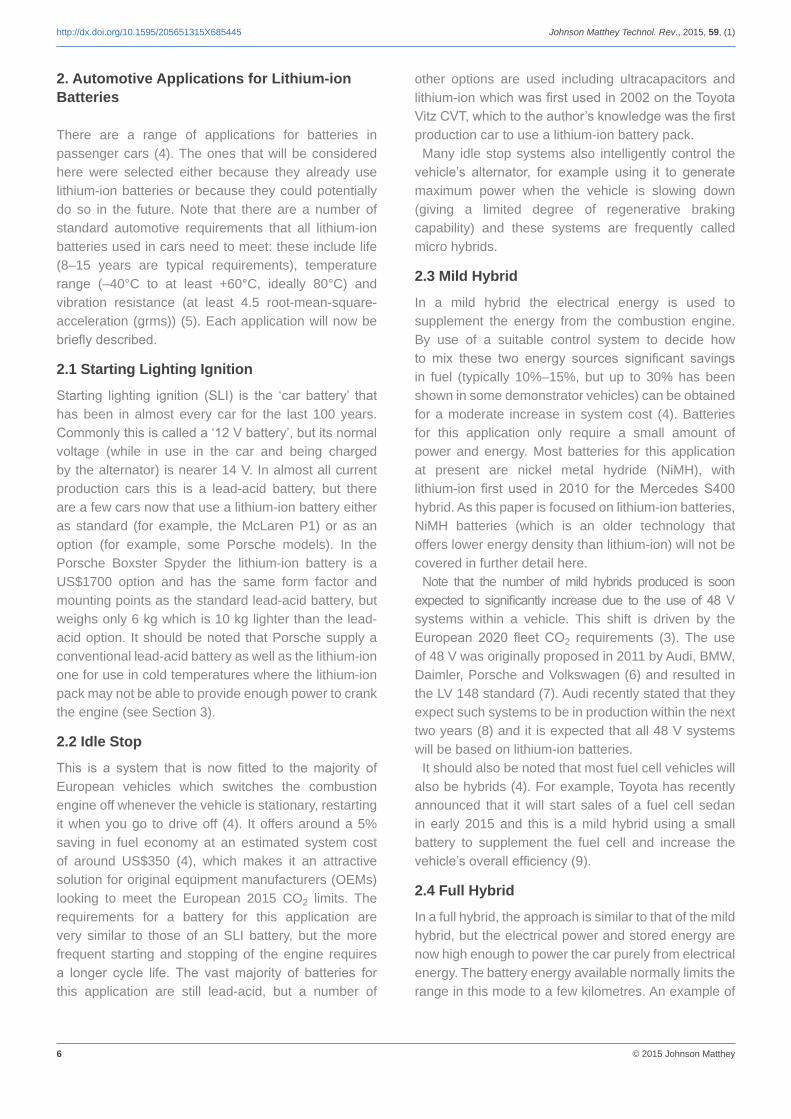
6 © 2015 Johnson Matthey
http://dx.doi.org/10.1595/205651315X685445 Johnson Matthey Technol. Rev., 2015, 59, (1)
2. Automotive Applications for Lithium-ion Batteries
There are a range of applications for batteries in passenger cars (4). The ones that will be considered here were selected either because they already use lithium-ion batteries or because they could potentially do so in the future. Note that there are a number of standard automotive requirements that all lithium-ion batteries used in cars need to meet: these include life (8–15 years are typical requirements), temperature range (–40°C to at least +60°C, ideally 80°C) and vibration resistance (at least 4.5 root-mean-square-acceleration (grms)) (5). Each application will now be briefly described.
2.1 Starting Lighting Ignition
Starting lighting ignition (SLI) is the ‘car battery’ that has been in almost every car for the last 100 years. Commonly this is called a ‘12 V battery’, but its normal voltage (while in use in the car and being charged by the alternator) is nearer 14 V. In almost all current production cars this is a lead-acid battery, but there are a few cars now that use a lithium-ion battery either as standard (for example, the McLaren P1) or as an option (for example, some Porsche models). In the Porsche Boxster Spyder the lithium-ion battery is a US$1700 option and has the same form factor and mounting points as the standard lead-acid battery, but weighs only 6 kg which is 10 kg lighter than the lead-acid option. It should be noted that Porsche supply a conventional lead-acid battery as well as the lithium-ion one for use in cold temperatures where the lithium-ion pack may not be able to provide enough power to crank the engine (see Section 3).
2.2 Idle Stop
This is a system that is now fitted to the majority of European vehicles which switches the combustion engine off whenever the vehicle is stationary, restarting it when you go to drive off (4). It offers around a 5% saving in fuel economy at an estimated system cost of around US$350 (4), which makes it an attractive solution for original equipment manufacturers (OEMs) looking to meet the European 2015 CO2 limits. The requirements for a battery for this application are very similar to those of an SLI battery, but the more frequent starting and stopping of the engine requires a longer cycle life. The vast majority of batteries for this application are still lead-acid, but a number of
other options are used including ultracapacitors and lithium-ion which was first used in 2002 on the Toyota Vitz CVT, which to the author’s knowledge was the first production car to use a lithium-ion battery pack.
Many idle stop systems also intelligently control the vehicle’s alternator, for example using it to generate maximum power when the vehicle is slowing down (giving a limited degree of regenerative braking capability) and these systems are frequently called micro hybrids.
2.3 Mild Hybrid
In a mild hybrid the electrical energy is used to supplement the energy from the combustion engine. By use of a suitable control system to decide how to mix these two energy sources significant savings in fuel (typically 10%–15%, but up to 30% has been shown in some demonstrator vehicles) can be obtained for a moderate increase in system cost (4). Batteries for this application only require a small amount of power and energy. Most batteries for this application at present are nickel metal hydride (NiMH), with lithium-ion first used in 2010 for the Mercedes S400 hybrid. As this paper is focused on lithium-ion batteries, NiMH batteries (which is an older technology that offers lower energy density than lithium-ion) will not be covered in further detail here.
Note that the number of mild hybrids produced is soon expected to significantly increase due to the use of 48 V systems within a vehicle. This shift is driven by the European 2020 fleet CO2 requirements (3). The use of 48 V was originally proposed in 2011 by Audi, BMW, Daimler, Porsche and Volkswagen (6) and resulted in the LV 148 standard (7). Audi recently stated that they expect such systems to be in production within the next two years (8) and it is expected that all 48 V systems will be based on lithium-ion batteries.
It should also be noted that most fuel cell vehicles will also be hybrids (4). For example, Toyota has recently announced that it will start sales of a fuel cell sedan in early 2015 and this is a mild hybrid using a small battery to supplement the fuel cell and increase the vehicle’s overall efficiency (9).
2.4 Full Hybrid
In a full hybrid, the approach is similar to that of the mild hybrid, but the electrical power and stored energy are now high enough to power the car purely from electrical energy. The battery energy available normally limits the range in this mode to a few kilometres. An example of
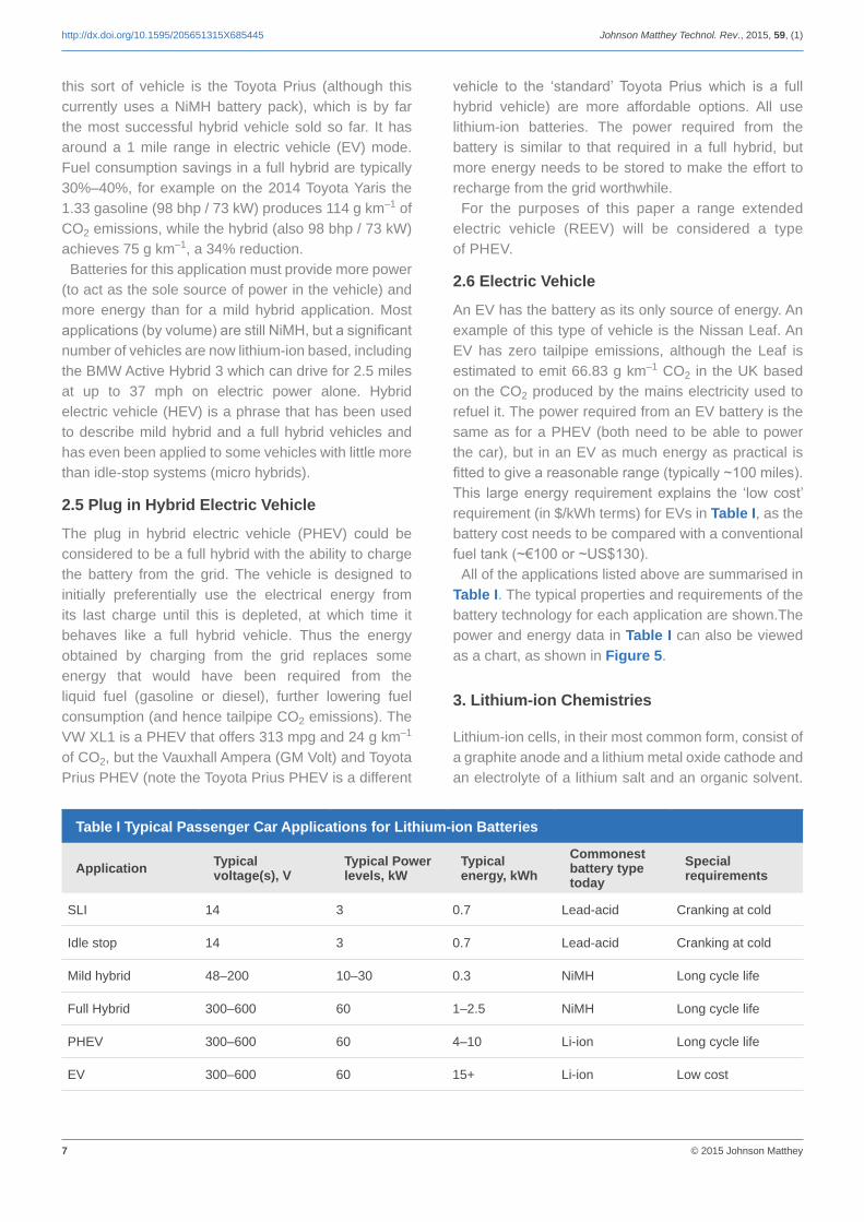
7 © 2015 Johnson Matthey
http://dx.doi.org/10.1595/205651315X685445 Johnson Matthey Technol. Rev., 2015, 59, (1)
this sort of vehicle is the Toyota Prius (although this currently uses a NiMH battery pack), which is by far the most successful hybrid vehicle sold so far. It has around a 1 mile range in electric vehicle (EV) mode. Fuel consumption savings in a full hybrid are typically 30%–40%, for example on the 2014 Toyota Yaris the 1.33 gasoline (98 bhp / 73 kW) produces 114 g km–1 of CO2 emissions, while the hybrid (also 98 bhp / 73 kW) achieves 75 g km–1, a 34% reduction.
Batteries for this application must provide more power (to act as the sole source of power in the vehicle) and more energy than for a mild hybrid application. Most applications (by volume) are still NiMH, but a significant number of vehicles are now lithium-ion based, including the BMW Active Hybrid 3 which can drive for 2.5 miles at up to 37 mph on electric power alone. Hybrid electric vehicle (HEV) is a phrase that has been used to describe mild hybrid and a full hybrid vehicles and has even been applied to some vehicles with little more than idle-stop systems (micro hybrids).
2.5 Plug in Hybrid Electric Vehicle
The plug in hybrid electric vehicle (PHEV) could be considered to be a full hybrid with the ability to charge the battery from the grid. The vehicle is designed to initially preferentially use the electrical energy from its last charge until this is depleted, at which time it behaves like a full hybrid vehicle. Thus the energy obtained by charging from the grid replaces some energy that would have been required from the liquid fuel (gasoline or diesel), further lowering fuel consumption (and hence tailpipe CO2 emissions). The VW XL1 is a PHEV that offers 313 mpg and 24 g km–1 of CO2, but the Vauxhall Ampera (GM Volt) and Toyota Prius PHEV (note the Toyota Prius PHEV is a different
vehicle to the ‘standard’ Toyota Prius which is a full hybrid vehicle) are more affordable options. All use lithium-ion batteries. The power required from the battery is similar to that required in a full hybrid, but more energy needs to be stored to make the effort to recharge from the grid worthwhile.
For the purposes of this paper a range extended electric vehicle (REEV) will be considered a type of PHEV.
2.6 Electric Vehicle
An EV has the battery as its only source of energy. An example of this type of vehicle is the Nissan Leaf. An EV has zero tailpipe emissions, although the Leaf is estimated to emit 66.83 g km–1 CO2 in the UK based on the CO2 produced by the mains electricity used to refuel it. The power required from an EV battery is the same as for a PHEV (both need to be able to power the car), but in an EV as much energy as practical is fitted to give a reasonable range (typically ~100 miles). This large energy requirement explains the ‘low cost’ requirement (in $/kWh terms) for EVs in Table I, as the battery cost needs to be compared with a conventional fuel tank (~€100 or ~US$130).
All of the applications listed above are summarised in Table I. The typical properties and requirements of the battery technology for each application are shown.The power and energy data in Table I can also be viewed as a chart, as shown in Figure 5.
3. Lithium-ion Chemistries
Lithium-ion cells, in their most common form, consist of a graphite anode and a lithium metal oxide cathode and an electrolyte of a lithium salt and an organic solvent.
Table I Typical Passenger Car Applications for Lithium-ion Batteries
Application Typical voltage(s), V
Typical Power levels, kW
Typical energy, kWh
Commonest battery type today
Special requirements
SLI 14 3 0.7 Lead-acid Cranking at cold
Idle stop 14 3 0.7 Lead-acid Cranking at cold
Mild hybrid 48–200 10–30 0.3 NiMH Long cycle life
Full Hybrid 300–600 60 1–2.5 NiMH Long cycle life
PHEV 300–600 60 4–10 Li-ion Long cycle life
EV 300–600 60 15+ Li-ion Low cost
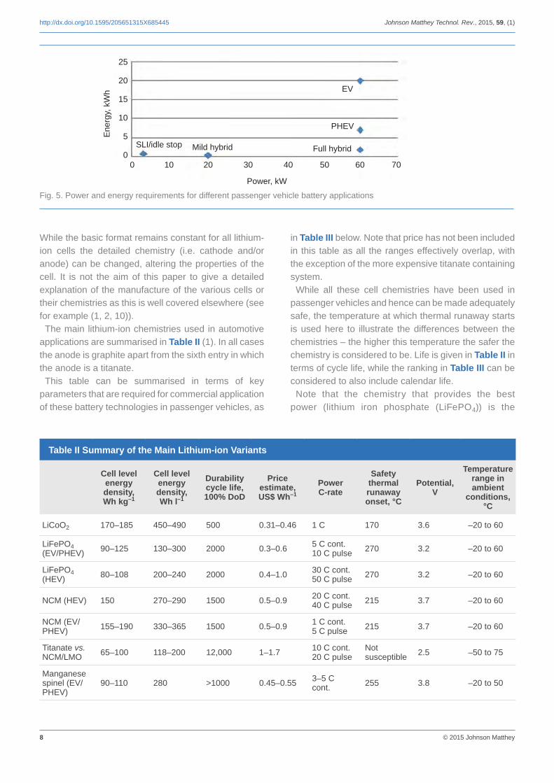
8 © 2015 Johnson Matthey
http://dx.doi.org/10.1595/205651315X685445 Johnson Matthey Technol. Rev., 2015, 59, (1)
Table II Summary of the Main Lithium-ion Variants
Cell level energy density, Wh kg–1
Cell level energy density, Wh l–1
Durability cycle life, 100% DoD
Price estimate, US$ Wh–1
Power C-rate
Safety thermal runaway onset, °C
Potential, V
Temperature range in ambient
conditions, °C
LiCoO2 170–185 450–490 500 0.31–0.46 1 C 170 3.6 –20 to 60
LiFePO4 (EV/PHEV) 90–125 130–300 2000 0.3–0.6 5 C cont.
10 C pulse 270 3.2 –20 to 60
LiFePO4 (HEV) 80–108 200–240 2000 0.4–1.0 30 C cont.
50 C pulse 270 3.2 –20 to 60
NCM (HEV) 150 270–290 1500 0.5–0.9 20 C cont. 40 C pulse 215 3.7 –20 to 60
NCM (EV/PHEV) 155–190 330–365 1500 0.5–0.9 1 C cont.
5 C pulse 215 3.7 –20 to 60
Titanate vs. NCM/LMO 65–100 118–200 12,000 1–1.7 10 C cont.
20 C pulseNot susceptible 2.5 –50 to 75
Manganese spinel (EV/PHEV)
90–110 280 >1000 0.45–0.55 3–5 C cont. 255 3.8 –20 to 50
While the basic format remains constant for all lithium-ion cells the detailed chemistry (i.e. cathode and/or anode) can be changed, altering the properties of the cell. It is not the aim of this paper to give a detailed explanation of the manufacture of the various cells or their chemistries as this is well covered elsewhere (see for example (1, 2, 10)).
The main lithium-ion chemistries used in automotive applications are summarised in Table II (1). In all cases the anode is graphite apart from the sixth entry in which the anode is a titanate.
This table can be summarised in terms of key parameters that are required for commercial application of these battery technologies in passenger vehicles, as
in Table III below. Note that price has not been included in this table as all the ranges effectively overlap, with the exception of the more expensive titanate containing system.
While all these cell chemistries have been used in passenger vehicles and hence can be made adequately safe, the temperature at which thermal runaway starts is used here to illustrate the differences between the chemistries – the higher this temperature the safer the chemistry is considered to be. Life is given in Table II in terms of cycle life, while the ranking in Table III can be considered to also include calendar life.
Note that the chemistry that provides the best power (lithium iron phosphate (LiFePO4)) is the
0 10 20 30 40 50 60 70
Power, kW
25
20
15
10
5
0
Ene
rgy,
kW
h
Fig. 5. Power and energy requirements for different passenger vehicle battery applications
SLI/idle stop Mild hybrid
EV
PHEV
Full hybrid

9 © 2015 Johnson Matthey
http://dx.doi.org/10.1595/205651315X685445 Johnson Matthey Technol. Rev., 2015, 59, (1)
Table III Key Parameters of Lithium-ion Chemistries
Parameter Highest performing chemistry(s) Lowest performing chemistry
Safety Titanate, LiFePO4 LiCoO2
Power LiFePO4 LiCoO2
Energy LiCoO2, NCM LiFePO4
Life Titanate, LiFePO4 LiCoO2
worst for energy. Both power and energy need to be considered when selecting candidate chemistries for applications and this idea will be explored further in Section 4.
The last parameter for consideration is low temperature performance and this is best shown by a graph (Figure 6 which is based on data from (11) with lithium-ion added by the present author based on measurements of an automotive LiFePO4 lithium-ion cell).
This graph shows that valve-regulated lead-acid (VRLA) battery technology offers significantly higher power at cold temperatures and so is better suited for cold cranking applications (which require the ability to crank the engine at –40°C).
4. Lithium-ion for Various Applications
One way to view the suitability of lithium-ion for various applications is to compare the power:energy ratio for the cells vs. the applications as shown in Figure 7. Here the yellow lines show the power:energy ratios for the various chemistries (from Table II), while the dots show the requirements for each of the applications (Figure 5). The lines closest to the dots
are likely to be the best fit to the application from a power and energy viewpoint, as chemistries with lines a long way away will have a significant excess of power or energy beyond the requirements. This is likely to make them a more expensive solution (in terms of cost, weight and volume) than solutions with lines close to the dot.
It can be seen that there are good matches for the mild and full hybrid and PHEV, but not a particularly good match for the EV requirements.
This means that companies offering a range of different types of hybrid vehicle will normally need to select multiple chemistries (which also normally means multiple suppliers). For example BMW uses A123 LiFePO4 cells in its hybrids, while it uses Samsung SDI (nickel-manganese-cobalt (NMC)) for its EV and PHEV vehicles (12), both of which can be seen to be sensible choices based on Figure 3. However there is no industry consensus, for example while BMW selected NMC for its EVs, Honda uses a titanate chemistry in its Fit EV and Renault uses spinel lithium manganese oxide (LMO) in the ZOE EV (13).
It should be noted that while lithium-ion batteries are in use in production cars, low temperature operation (see
–40 –20 0 20 40 60
Temperature, ºC
1800
1600
1400
1200
1000
800
600
400200
0
Pow
er, W
kg–1
VRLA (W kg–1) (11)
NiMH (W kg–1) (11)
Li-ion (W kg–1)
Fig. 6. Low temperature performance of selected battery chemistries
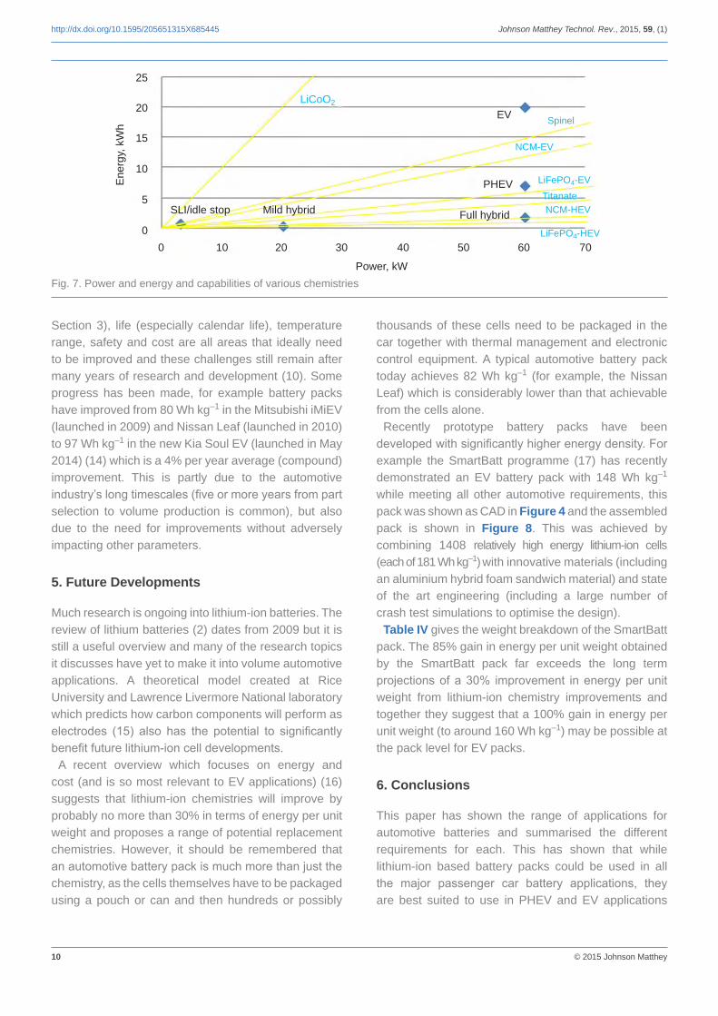
10 © 2015 Johnson Matthey
http://dx.doi.org/10.1595/205651315X685445 Johnson Matthey Technol. Rev., 2015, 59, (1)
Section 3), life (especially calendar life), temperature range, safety and cost are all areas that ideally need to be improved and these challenges still remain after many years of research and development (10). Some progress has been made, for example battery packs have improved from 80 Wh kg–1 in the Mitsubishi iMiEV (launched in 2009) and Nissan Leaf (launched in 2010) to 97 Wh kg–1 in the new Kia Soul EV (launched in May 2014) (14) which is a 4% per year average (compound) improvement. This is partly due to the automotive industry’s long timescales (five or more years from part selection to volume production is common), but also due to the need for improvements without adversely impacting other parameters.
5. Future Developments
Much research is ongoing into lithium-ion batteries. The review of lithium batteries (2) dates from 2009 but it is still a useful overview and many of the research topics it discusses have yet to make it into volume automotive applications. A theoretical model created at Rice University and Lawrence Livermore National laboratory which predicts how carbon components will perform as electrodes (15) also has the potential to significantly benefit future lithium-ion cell developments.
A recent overview which focuses on energy and cost (and is so most relevant to EV applications) (16) suggests that lithium-ion chemistries will improve by probably no more than 30% in terms of energy per unit weight and proposes a range of potential replacement chemistries. However, it should be remembered that an automotive battery pack is much more than just the chemistry, as the cells themselves have to be packaged using a pouch or can and then hundreds or possibly
thousands of these cells need to be packaged in the car together with thermal management and electronic control equipment. A typical automotive battery pack today achieves 82 Wh kg–1 (for example, the Nissan Leaf) which is considerably lower than that achievable from the cells alone.
Recently prototype battery packs have been developed with significantly higher energy density. For example the SmartBatt programme (17) has recently demonstrated an EV battery pack with 148 Wh kg–1 while meeting all other automotive requirements, this pack was shown as CAD in Figure 4 and the assembled pack is shown in Figure 8. This was achieved by combining 1408 relatively high energy lithium-ion cells (each of 181 Wh kg–1) with innovative materials (including an aluminium hybrid foam sandwich material) and state of the art engineering (including a large number of crash test simulations to optimise the design).
Table IV gives the weight breakdown of the SmartBatt pack. The 85% gain in energy per unit weight obtained by the SmartBatt pack far exceeds the long term projections of a 30% improvement in energy per unit weight from lithium-ion chemistry improvements and together they suggest that a 100% gain in energy per unit weight (to around 160 Wh kg–1) may be possible at the pack level for EV packs.
6. Conclusions
This paper has shown the range of applications for automotive batteries and summarised the different requirements for each. This has shown that while lithium-ion based battery packs could be used in all the major passenger car battery applications, they are best suited to use in PHEV and EV applications
0 10 20 30 40 50 60 70
Power, kW
25
20
15
10
5
0
Ene
rgy,
kW
h
SLI/idle stop Mild hybrid
LiCoO2
EV
PHEV
Full hybrid
Spinel
NCM-EV
LiFePO4-EV
TitanateNCM-HEV
LiFePO4-HEV
Fig. 7. Power and energy and capabilities of various chemistries

11 © 2015 Johnson Matthey
http://dx.doi.org/10.1595/205651315X685445 Johnson Matthey Technol. Rev., 2015, 59, (1)
Fig. 8. SmartBatt battery pack
Table IV SmartBatt Weight Breakdown
Component Mass, kg Fraction, %
Housing 8.5 5.5
Module without cells 16.6 10.7
Cells 125.3 80.6
Electrical components 2.1 1.4
Electrical connections 2.9 1.9
TOTAL 155.4 –
and are least suited to SLI applications. Even for the applications where lithium-ion is being used, it has been shown that different vehicle OEMs have selected different chemistries for the same application based on different interpretations of the trade-offs between the chemistries’ performance and the requirements of the specific application.
It has been stated that new lithium-ion chemistries offer limited potential for improvement (~30% in terms of Wh kg–1) which has resulted in significant research in non lithium-ion based chemistries which offer the promise of significantly higher gains (16). However it is shown here that, especially for EV battery packs, major weight gains can come from the overall design of the battery pack and these together with better chemistries suggest that a doubling of the energy per unit weight for EV battery packs is possible in the relatively near future.
Acknowledgments
The author wishes to thank the anonymous referees and the editor for their constructive comments as well as Johnson Matthey for permission to publish this paper.
References1. “Johnson Matthey Battery Systems: Our Guide to
Batteries”, 2nd Edn., Johnson Matthey Plc, Dundee, UK, 2012
2. B. Scrosati and J. Garche, J. Power Sources, 2010, 195, (9), 2419
3. ‘Setting Emission Performance Standards for New Passenger Cars as Part of the Community’s Integrated Approach to Reduce CO2 Emissions from Light-Duty Vehicles’, Regulation (EC) No 443/2009 of the European Parliament and of the Council of 23 April 2009, Official J. Eur. Union, L 140/1, 5th June, 2009
4. P. Miller, IEEJ Trans. Ind. Appl., 2008, 128, (7), 880
5. P. Miller, T. Dobedoe, G. Duncan, T. Pike, D. Sharred and P. Smout, ‘Surge Transport and its Role in Technology Transfer of Environmental Awareness in the Transport Sector’, IEE Seminar on Automotive Electronic Standards; Are They?, IET London, Savoy Place, UK, 1999, Ref. No. 1999/206, pp. 4/1–4/8
6. C. Hammerschmidt, ‘German Carmakers Agree on 48V On-board Supply, Charging Plug’, Automotive EE Times Europe, 16th June, 2011, 222901632
7. M. Kuypers, ‘Application of 48 Volt for Mild Hybrid Vehicles and High Power Loads’, SAE Paper 2014-01-1790

12 © 2015 Johnson Matthey
http://dx.doi.org/10.1595/205651315X685445 Johnson Matthey Technol. Rev., 2015, 59, (1)
8. C. Hammerschmidt, ‘Audi Makes the Leap to 48V Supply’, Automotive EE Times Europe, 25th August, 2014, 222903784
9. S. Bickerstaffe, ‘Elemental Decision’, Automotive Engineer, 1st January, 2014, pp. 33–34
10. A. Jossen, ‘Overview on Current Status of Lithium-ion Batteries’, Second International Renewable Energy Storage Conference (IRES II), Bonn, Germany, 19th–21st November, 2007
11. M. J. Weighall, J. Power Sources, 2003, 116, (1–2), 151
12. P. Buckley, ‘Samsung SDI Batteries to Drive Future BMW EVs’, EE Times Europe, 15th July, 2014
13. C. Garnier, ‘Renault ZE: Path Toward EV Battery Production’, CAPIRE Workshop, Brussels, Belgium, 10th April, 2013
14. ‘Bosch Set to Double Battery Energy Density’, Automotive Engineer, 2014, 39, (2), 5
15 Y. Liu, Y. M. Wang, B. I. Yakobson and B. C. Wood, Phys. Rev. Lett., 2014, 113, 028304
16. R. Van Noorden, Nature, 2014, 507, (7490), 26
17. H. Kapeller, ‘SmartBatt: Smart and Safe Integration of Batteries in Electric Vehicles’, The 27th International Electric Vehicle Symposium (EVS27), Barcelona, Spain, 17th–20th November, 2013
The Author
In December 2013 Dr Peter Miller took up the role of Chief Electronics Technologist at Johnson Matthey Battery Systems. Prior to this he was the Director, Electrical/Electronic Engineering at Ricardo and until 2001 he was the European Director of Technology at Motorola Automotive/Industrial Electronics Group. His primary interests relate to the design, control and use of lithium-ion batteries. Dr Miller is the author of a large number papers and patents. He holds a BSc and PhD from Hull University, UK, is a Chartered Engineer, a fellow of the Institute of Engineering and Technology (IET) and a member of the Institute of Electrical and Electronics Engineers (IEEE) and the Association of Computing Machinery (ACM).

www.technology.matthey.comJOHNSON MATTHEY TECHNOLOGY REVIEW
http://dx.doi.org/10.1595/205651317X693624 Johnson Matthey Technol. Rev., 2017, 61, (1), 52–59
52 © 2017 Johnson Matthey
Platinum Group Metal Compounds in Cancer ChemotherapyAn overview of the history and the potential of anticancer pgm compounds
By Christopher BarnardStoke Row, Oxfordshire, UK
Email: [email protected]
It was some 50 years ago that Barnett Rosenberg and coworkers published their studies on unusual patterns of bacterial growth that led to the identification of platinum compounds as highly effective agents against some cancers, particularly those of genitourinary origin. This sparked a renewed interest around the world in the potential of metal compounds as small molecule therapeutic agents. Some of that history, particularly related to the platinum group metals (pgm) platinum and ruthenium, is described in this overview.
The First Drug – Cisplatin
The application of platinum compounds in cancer therapy was one of the most unexpected developments in pharmaceuticals in the last 50 years. Many reviews have been published previously on this topic; in this journal the most recent being by Reedijk in 2008 (1).
The potential of platinum compounds was discovered by Rosenberg in 1965 (2). He had recently taken up an interdisciplinary post as Professor of Biophysics at Michigan State University, USA. Coming from a physics background with little experience in biological sciences one of his early experiments was to study the effect
of electromagnetic fields on cell division. In a fortunate combination of circumstances, he conducted a test experiment with platinum electrodes, an ammoniacal medium and Escherichia coli as the test organism. He observed unusual filamentous growth that he was later able to attribute to the formation of soluble platinum ammine complexes. After further study he approached the National Cancer Institute (NCI), USA, to demonstrate whether the key compound, cis-PtCl2(NH3)2, could also affect the growth of cancer cells. The activity was significant and encouraged the NCI to support the clinical evaluation of cisplatin, as this compound came to be known (3). The action of cisplatin was subsequently determined to arise from its interaction with deoxyribonucleic acid (DNA), in particular forming intrastrand cross-links between neighbouring guanosine residues. Over many years much effort was put into studying the detail of this lesion and its interactions with proteins which might mediate the cell death process (4, 5).
Early clinical results were variable, with occasional patients showing very positive results while others encountered marked toxic effects such as kidney and nerve damage. While these side effects remained uncontrolled there seemed little likelihood of cisplatin achieving regulatory approval, but fortunately a new administration procedure involving pre- and post-hydration significantly reduced the kidney toxicity (but did not eliminate it) (6). This allowed somewhat higher doses to be given to patients with acceptable

53 © 2017 Johnson Matthey
http://dx.doi.org/10.1595/205651317X693624 Johnson Matthey Technol. Rev., 2017, 61, (1)
toxic risk and pronounced activity in genitourinary cancers (particularly testicular and ovarian cancer) was observed. On this basis, the NCI and Research Corporation (on behalf of Michigan State University) licensed the marketing of cisplatin (Figure 1) to Bristol-Myers, USA, with marketing approval being gained in the USA in 1978 and many other countries, including the UK, the following year.
Second Generation – Carboplatin
To raise support for his continuing work at Michigan State University and promote interest in his discovery Professor Rosenberg toured and corresponded widely. This included contact with the platinum companies Rustenburg Platinum Mines Ltd, South Africa (pgm mining and supply), and Engelhard Corp, USA, and Johnson Matthey Plc, UK (both specialised in pgm marketing). To obtain a better understanding of this technology Johnson Matthey and Engelhard sent postgraduate researchers, Michael Cleare and James Hoeschele respectively, to work in Professor Rosenberg’s research group. Cleare decided to study the structure-activity relationships of platinum complexes, resulting in the synthesis of various pgm complexes and a series of publications describing this work (see, for example (7–9)). On returning to the UK, Cleare, with Rustenburg’s support, coordinated the exchange of results between a number of researchers interested in the new field. After the marketing of cisplatin, he was instrumental in linking Bristol-Myers, Johnson Matthey and the Institute of Cancer Research (ICR), UK, to identify a second generation alternative to cisplatin. The aim of the programme was to increase the therapeutic potential of the drug either by decreasing the toxicity, particularly kidney toxicity, associated with its use or by increasing the potency and thus effectiveness at lower doses.
Ultimately, it was the former of these targets which proved easier to achieve. From the compounds originally synthesised at Michigan State University by Cleare, diammine-1,1-cyclobutanedicarboxylatoplatinum(II), carboplatin (Figure 1), was found by the ICR to have the best balance of antitumour activity and low toxicity for taking forward to clinical trials (10). Due to the close links between the ICR and the Royal Marsden Hospital, London, UK, with the support of Bristol-Myers, the compound was progressed rapidly through clinical trials and granted its first marketing approval for treating ovarian cancer in 1986.
Other Second Generation Compounds – Oxaliplatin
Bristol-Myers and Johnson Matthey investigated another second generation compound, iproplatin (JM-9, Figure 2), in this case with the pre-clinical studies being carried out by the Roswell Park Cancer Institute, USA, in addition to work at ICR (11). In clinical trials this drug had similar activity to carboplatin but toxicities proved more difficult to control (12). Bristol-Myers also pursued the development of spiroplatin (TNO-6, Figure 2) a compound synthesised at the Dutch Institute of Applied Chemistry, Nederlandse Organisatie Voor Toegepast Natuurwetenschappelijk Onderzoek (TNO), The Netherlands. In this case problems were encountered with kidney toxicity and limited activity (13). Therefore, Bristol-Myers chose to concentrate its further efforts on gaining marketing approval for carboplatin.
A significant number of compounds were investigated in early stage clinical trials by other organisations, both commercial and academic (12, 14). Some examples are given in Figure 2. Some of these gained local market approval including nedaplatin (AquplaTM, 254-S), Shionogi Pharmaceuticals, Japan; lobaplatin, Asta Medica, China; heptaplatin (eptaplatin), SK Chemicals Life Sciences, Korea, see Figure 3. However, one compound that has achieved widespread use is oxaliplatin (Figure 1). This compound incorporates the 1,2-diaminocyclohexane ligand that was favoured in early studies by the NCI, the same ligand being incorporated into JM-82 ((1,2-diaminocyclohexane)(trimellitic acid)platinum(II)) and tetraplatin (ormaplatin, Figure 2) which entered clinical trials but were not marketed. Oxaliplatin (named as l-OHP) was first reported by Kidani and Mathé (15) who initiated clinical trials (16). Development was continued by Debiopharm GroupTM, a small Swiss company, with
Cisplatin Carboplatin
PtCl
Cl
H3N
H3NPt
H3N
H3N
O
OO
O
PtN H2
H2 N O
O O
O
Oxaliplatin
Fig. 1. Globally marketed platinum-containing drugs

54 © 2017 Johnson Matthey
http://dx.doi.org/10.1595/205651317X693624 Johnson Matthey Technol. Rev., 2017, 61, (1)
clinicians conducting a number of trials to find the best administration schedule that would maximise the activity while controlling the toxicity. Pre-clinical testing in mice had shown that toxicities could be reduced when the drug was given with circadian periodicity (17). By appropriate scheduling of administration in patients (chronotherapy) it was found that toxicities, such as neutropenia and paraesthesia, were less frequent and improved responses were seen in colon cancer when used together with 5-fluorouracil (18). The drug was then licensed to Sanofi, France, for marketing
worldwide with the major indications being adjuvant and metastatic colorectal cancers.
Third Generation – Satraplatin
Following the success of their collaboration on carboplatin, Johnson Matthey, ICR and Bristol-Myers Squibb (following their merger) reviewed their options for further developments in this field. Two targets were identified; firstly, to adapt the platinum agents to provide an orally administered drug as an alternative to the intravenously injectable cisplatin and carboplatin and, secondly, to achieve activity in tumours which were resistant, or had acquired resistance, to cisplatin. Significant progress on the first target came when Giandomenico described versatile routes for converting platinum(IV) hydroxido complexes to their carboxylate counterparts (19). Selecting a compound for clinical trials required careful judgement on balancing the antitumour activity with emetic potential. The compound selected was cis-ammine(cyclohexylamine)-cis-dichlorido-trans(diacetato)platinum(IV), satraplatin (JM-216, Figure 4) (20). After some years of clinical trials on hormone resistant prostate cancer, it was determined that the compound did not result in significant life
PtCl
ClN H2
H2 N
OH
OHIproplatin Spiroplatin DAC-TMA
H2 N
N H2
PtO
OS
O
O
H2 N
N H2
PtO
OO
OCO2H
Tetraplatin Zeniplatin Enloplatin
PtCl
ClN H2
H2 N
Cl
Cl
PtO
OO
O
H2 N
N H2
HO
HOPt
O
OO
O
H2 N
N H2
O
Miboplatin Sebriplatin
PtO
OO
OO
OO
O
H2 N
N H2
H3CH2 N
PtNH
H
Fig. 2. Second generation platinum compounds evaluated in clinical trials
Nedaplatin Lobaplatin
Heptaplatin
PtO
O
OH3N
H3NPt
O
O
O
H2 N
N H2
PtO
OO
ON H2
H2 N
Fig. 3. Regionally marketed platinum-containing drugs
O
O
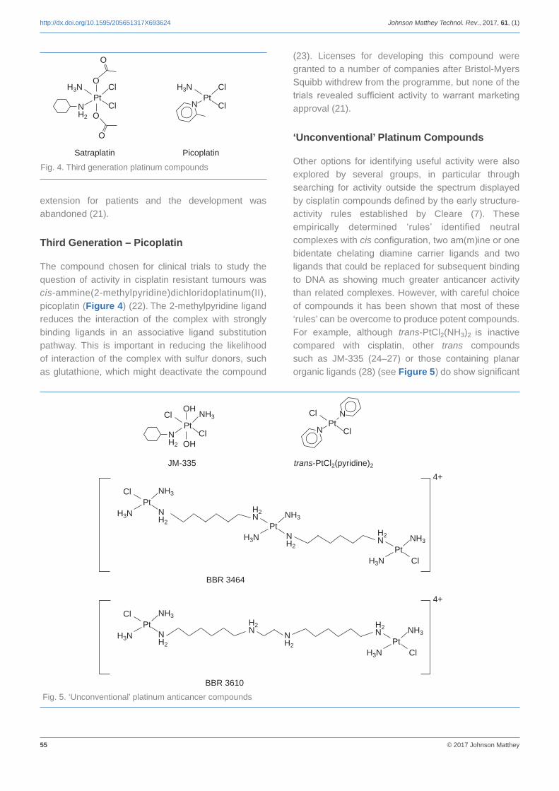
55 © 2017 Johnson Matthey
http://dx.doi.org/10.1595/205651317X693624 Johnson Matthey Technol. Rev., 2017, 61, (1)
extension for patients and the development was abandoned (21).
Third Generation – Picoplatin
The compound chosen for clinical trials to study the question of activity in cisplatin resistant tumours was cis-ammine(2-methylpyridine)dichloridoplatinum(II), picoplatin (Figure 4) (22). The 2-methylpyridine ligand reduces the interaction of the complex with strongly binding ligands in an associative ligand substitution pathway. This is important in reducing the likelihood of interaction of the complex with sulfur donors, such as glutathione, which might deactivate the compound
(23). Licenses for developing this compound were granted to a number of companies after Bristol-Myers Squibb withdrew from the programme, but none of the trials revealed sufficient activity to warrant marketing approval (21).
‘Unconventional’ Platinum Compounds
Other options for identifying useful activity were also explored by several groups, in particular through searching for activity outside the spectrum displayed by cisplatin compounds defined by the early structure-activity rules established by Cleare (7). These empirically determined ‘rules’ identified neutral complexes with cis configuration, two am(m)ine or one bidentate chelating diamine carrier ligands and two ligands that could be replaced for subsequent binding to DNA as showing much greater anticancer activity than related complexes. However, with careful choice of compounds it has been shown that most of these ‘rules’ can be overcome to produce potent compounds. For example, although trans-PtCl2(NH3)2 is inactive compared with cisplatin, other trans compounds such as JM-335 (24–27) or those containing planar organic ligands (28) (see Figure 5) do show significant
Satraplatin Picoplatin
Fig. 4. Third generation platinum compounds
PtCl
Cl
H3N
NPt
Cl
Cl
H3N
N H2
O
O
O
O
Fig. 5. ‘Unconventional’ platinum anticancer compounds
JM-335 trans-PtCl2(pyridine)2
PtCl
Cl
NH3
N H2
OH
OH
PtCl
ClN
N
PtCl NH3
N H2
H3NPt
NH3
N H2
H3N
H2 N
PtNH3
H3N
H2 N
Cl
BBR 3464
4+
PtCl NH3
N H2
H3N N H2
H2 N
PtNH3
H3N
H2 N
Cl
BBR 3610
4+

56 © 2017 Johnson Matthey
http://dx.doi.org/10.1595/205651317X693624 Johnson Matthey Technol. Rev., 2017, 61, (1)
activity. However, results from testing cisplatin-resistant xenograft tumours were not sufficiently encouraging for these compounds to be taken forward to clinical study. Dinuclear or oligonuclear complexes of platinum can form different lesions on DNA compared to monomeric cisplatin and this is another area that has been investigated (29). Of particular interest in this regard is the ionic trinuclear complex BBR3464 (Figure 5) (30). This compound was developed for clinical trials by Boehringer Mannheim Italia, Italy, but again the level of activity was not sufficient to justify large scale phase III trials (31, 32).
Ruthenium Compounds
As it became increasingly apparent that an immense effort would be required to identify a platinum compound with improved therapeutic properties over cisplatin, carboplatin and oxaliplatin, so many researchers turned to other metals to open up new avenues to identifying compounds which might offer activity where cisplatin was ineffective. Ruthenium complexes were among the first suggested for detailed study (33) and a number of different compounds have been followed up. Early studies of a wide range of metal complexes identified ruthenium dimethylsulfoxide (DMSO) complexes, both cis- and trans-[RuCl4(DMSO)2], as being of interest (34). Ruthenium oxidation states II, III and IV are stable in water in various complexes. Ruthenium(III) complexes are relatively inert to
substitution compared with ruthenium(II) and this suggested the potential of ruthenium(III) compounds to act as prodrugs for ruthenium(II) species which might be formed by reduction in the body (33). This theory became known as ‘activation by reduction’ and relied on the fact that tumour masses grow without the associated development of vascularisation systems typical of normal tissue and so offer a less oxygen rich and hence more reducing environment of lower pH than normal tissues. Thus the action of the complexes might be enhanced relative to normal tissue.
Ruthenium(III) Complexes
This theory was evaluated during the development of Na[RuCl4(DMSO)(Im)] (NAMI, Im = imidazole) (34). Results from testing against lung and mammary tumours in mice were encouraging, but NAMI lacked many of the ideal physical characteristics for pharmaceutical development. In particular, the compound is hygroscopic and crystallises with two DMSO molecules of crystallisation resulting in variability in elemental composition and poor stability. Many of these problems were resolved by switching to the imidiazolium salt [ImH][RuCl4(DMSO)(Im)] (NAMI-A, Figure 6) (35). This has no molecules of crystallisation resulting in good stability and has good solubility in water. In addition, its synthesis from ruthenium trichloride is a simple and high yielding process. Solution studies showed that the complex is likely to undergo chloride hydrolysis in
Fig. 6. Ruthenium anticancer compounds
NAMI-A NKP 1339 RM 175
RuCl
Cl
SO
Cl
ClN
N H
N H
NH
+
–
RuCl
Cl
Cl
ClN
HN
NNH
–
Na+
RuCl
+
H2NNH2
PF6–
RAPTA-C RDC 11
RuClCl
P N
N N
Ru
+PF6
–N
N
NCCH3NCCH3
N
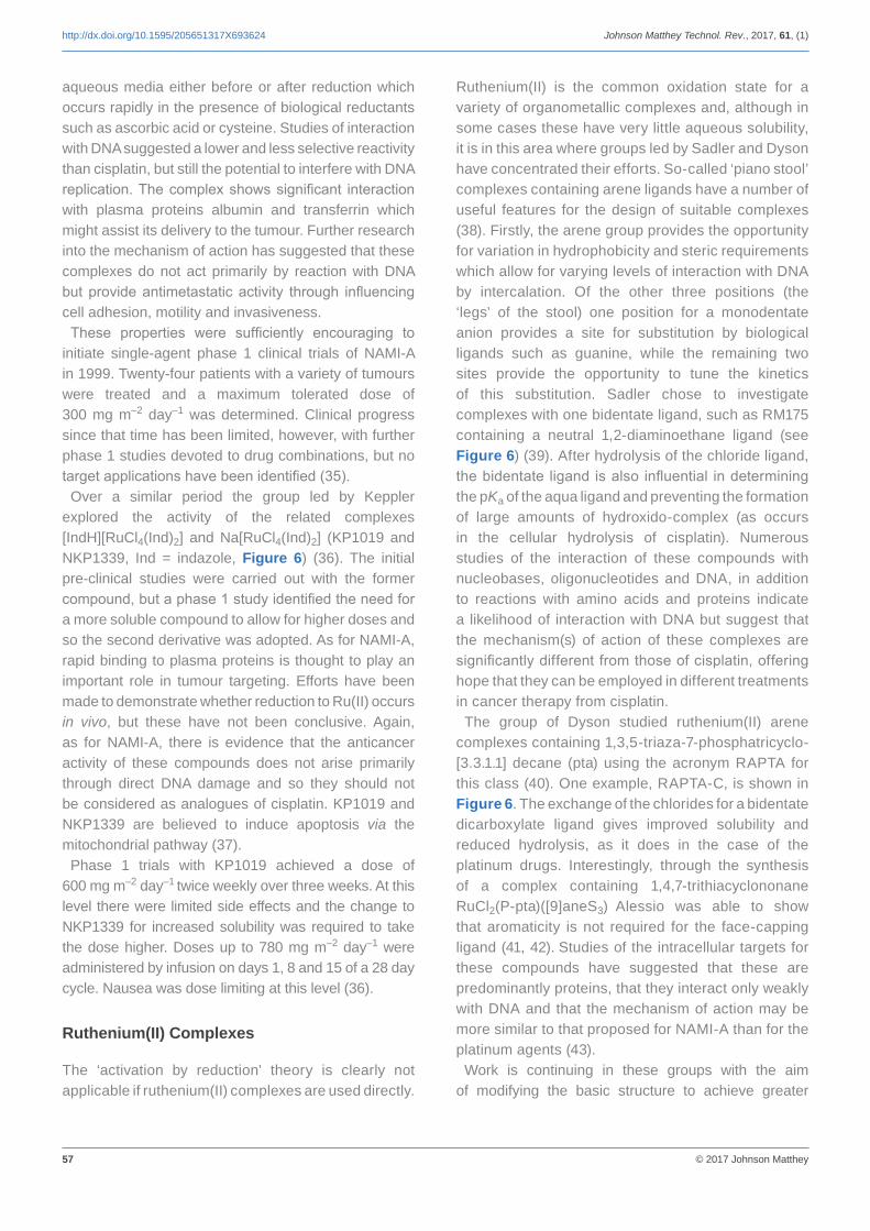
57 © 2017 Johnson Matthey
http://dx.doi.org/10.1595/205651317X693624 Johnson Matthey Technol. Rev., 2017, 61, (1)
aqueous media either before or after reduction which occurs rapidly in the presence of biological reductants such as ascorbic acid or cysteine. Studies of interaction with DNA suggested a lower and less selective reactivity than cisplatin, but still the potential to interfere with DNA replication. The complex shows significant interaction with plasma proteins albumin and transferrin which might assist its delivery to the tumour. Further research into the mechanism of action has suggested that these complexes do not act primarily by reaction with DNA but provide antimetastatic activity through influencing cell adhesion, motility and invasiveness.
These properties were sufficiently encouraging to initiate single-agent phase 1 clinical trials of NAMI-A in 1999. Twenty-four patients with a variety of tumours were treated and a maximum tolerated dose of 300 mg m–2 day–1 was determined. Clinical progress since that time has been limited, however, with further phase 1 studies devoted to drug combinations, but no target applications have been identified (35).
Over a similar period the group led by Keppler explored the activity of the related complexes [IndH][RuCl4(Ind)2] and Na[RuCl4(Ind)2] (KP1019 and NKP1339, Ind = indazole, Figure 6) (36). The initial pre-clinical studies were carried out with the former compound, but a phase 1 study identified the need for a more soluble compound to allow for higher doses and so the second derivative was adopted. As for NAMI-A, rapid binding to plasma proteins is thought to play an important role in tumour targeting. Efforts have been made to demonstrate whether reduction to Ru(II) occurs in vivo, but these have not been conclusive. Again, as for NAMI-A, there is evidence that the anticancer activity of these compounds does not arise primarily through direct DNA damage and so they should not be considered as analogues of cisplatin. KP1019 and NKP1339 are believed to induce apoptosis via the mitochondrial pathway (37).
Phase 1 trials with KP1019 achieved a dose of 600 mg m–2 day–1 twice weekly over three weeks. At this level there were limited side effects and the change to NKP1339 for increased solubility was required to take the dose higher. Doses up to 780 mg m–2 day–1 were administered by infusion on days 1, 8 and 15 of a 28 day cycle. Nausea was dose limiting at this level (36).
Ruthenium(II) Complexes
The ‘activation by reduction’ theory is clearly not applicable if ruthenium(II) complexes are used directly.
Ruthenium(II) is the common oxidation state for a variety of organometallic complexes and, although in some cases these have very little aqueous solubility, it is in this area where groups led by Sadler and Dyson have concentrated their efforts. So-called ‘piano stool’ complexes containing arene ligands have a number of useful features for the design of suitable complexes (38). Firstly, the arene group provides the opportunity for variation in hydrophobicity and steric requirements which allow for varying levels of interaction with DNA by intercalation. Of the other three positions (the ‘legs’ of the stool) one position for a monodentate anion provides a site for substitution by biological ligands such as guanine, while the remaining two sites provide the opportunity to tune the kinetics of this substitution. Sadler chose to investigate complexes with one bidentate ligand, such as RM175 containing a neutral 1,2-diaminoethane ligand (see Figure 6) (39). After hydrolysis of the chloride ligand, the bidentate ligand is also influential in determining the pKa of the aqua ligand and preventing the formation of large amounts of hydroxido-complex (as occurs in the cellular hydrolysis of cisplatin). Numerous studies of the interaction of these compounds with nucleobases, oligonucleotides and DNA, in addition to reactions with amino acids and proteins indicate a likelihood of interaction with DNA but suggest that the mechanism(s) of action of these complexes are significantly different from those of cisplatin, offering hope that they can be employed in different treatments in cancer therapy from cisplatin.
The group of Dyson studied ruthenium(II) arene complexes containing 1,3,5-triaza-7-phosphatricyclo- [3.3.1.1] decane (pta) using the acronym RAPTA for this class (40). One example, RAPTA-C, is shown in Figure 6. The exchange of the chlorides for a bidentate dicarboxylate ligand gives improved solubility and reduced hydrolysis, as it does in the case of the platinum drugs. Interestingly, through the synthesis of a complex containing 1,4,7-trithiacyclononane RuCl2(P-pta)([9]aneS3) Alessio was able to show that aromaticity is not required for the face-capping ligand (41, 42). Studies of the intracellular targets for these compounds have suggested that these are predominantly proteins, that they interact only weakly with DNA and that the mechanism of action may be more similar to that proposed for NAMI-A than for the platinum agents (43).
Work is continuing in these groups with the aim of modifying the basic structure to achieve greater

58 © 2017 Johnson Matthey
http://dx.doi.org/10.1595/205651317X693624 Johnson Matthey Technol. Rev., 2017, 61, (1)
selectivity of action or applications to other treatment methods (44).
Another group of organometallic derivatives with only a single Ru-C linkage has been reported by Pfeffer and coworkers (45). The complex RDC11 (see Figure 6) contains a chelating phenylpyridine ligand. As with other ruthenium compounds there is evidence that direct interaction with DNA is less important for the action of this compound than for cisplatin and this opens the way for extending the application of metal-based drugs to additional tumours, creating new possibilities for combination therapies.
Conclusions
It is notable that each of these last investigations is being undertaken in academic groups without the sponsorship of a major pharmaceutical company. With our increasing understanding of genomics in recent years the focus for the pharmaceutical industry is moving towards identifying treatments that play a more direct role in controlling cancer development than can be provided by small molecule chemotherapy. Nevertheless, experience tells us that the opening up of new fields such as this will take longer than anticipated and time still remains for new small molecule drugs to find a place in cancer therapy.
References
1. J. Reedijk, Platinum Metals Rev., 2008, 52, (1), 2
2. B. Rosenberg, L. Van Camp and T. Krigas, Nature, 1965, 205, (4972), 698
3. B. Rosenberg, L. VanCamp, J. E. Trosko and V. H. Mansour, Nature, 1969, 222, (5191), 385
4. E. R. Jamieson and S. J. Lippard, Chem. Rev., 1999, 99, (9), 2467
5. U.-M. Ohndorf, M. A. Rould, Q. He, C. O. Pabo and S. J. Lippard, Nature, 1999, 399, (6737), 708
6. E. Cvitkovic, J. Spaulding, V. Bethune, J. Martin and W. F. Whitmore, Cancer, 1977, 39, (4), 1357
7. M. J. Cleare and J. D. Hoeschele, Bioinorg. Chem., 1973, 2, (3), 187
8. M. J. Cleare, Coord. Chem. Rev., 1974, 12, (4), 349
9. T. A. Connors, M. J. Cleare and K. R. Harrap, Cancer Treat. Rep., 1979, 63, (9–10), 1499
10. K. R. Harrap, Cancer Treat. Rev., 1985, 12, (A), 21
11. C. F. J. Barnard, M. J. Cleare and P. C. Hydes, Chem. Br., 1986, 22, 1001
12. N. J. Wheate, S. Walker, G. E. Craig and R. Oun, Dalton Trans., 2010, 39, (35), 8113
13. J. B. Vermorken, W. W. ten Bokkel Huinink, J. G. McVie, W. J. F. van der Vijgh and H. M. Pinedo, ‘Clinical Experience with 1,1-Diaminomethylcyclohexane (Sulphato) Platinum (II) (TNO-6)’, Platinum Coordination Complexes in Cancer Chemotherapy, Vermont Regional Cancer Center and the Norris Cotton Cancer Center, USA, 22nd–24th June, 1983, “Proceedings of the Fourth International Symposium on Platinum Coordination Complexes in Cancer Chemotherapy”, eds. M. P. Hacker. E. B. Douple and I. H. Krakoff, Martinus Nijhoff Publishing, Boston, USA, 1984, p. 330
14. M. C. Christian, Semin. Oncol., 1992, 19, (6), 720
15. G. Mathé, Y. Kidani, M. Noji, R. Maral, C. Bourut and E. Chenu, Cancer Lett., 1985, 27, (2) 135
16. G. Mathé, Y. Kidani, K. Triana, S. Brienza, P. Ribaud, E. Goldschmidt, E. Ecstein, R. Despax, M. Musset and J. L. Misset, Biomed. Pharmacother., 1986, 40, (10), 372
17. A. N. Boughattas, F. Lévi, C. Fournier, G. Lemaigre, A. Roulon, B. Hecquet, G. Mathé and A. Reinberg, Cancer Res., 1989, 49, (12), 3362
18. F. Lévi, J.-L. Misset, S. Brienza, R. Adam, G. Metzger, M. Itzakhi, J. P. Caussanel, F. Kunstlinger, S. Lecouturier, A. Descorps-Declère, C. Jasmin, H. Bismuth and A. Reinberg, Cancer, 1992, 69, (4), 893
19. C. M. Giandomenico, M. J. Abrams, B. A. Murrer, J. F. Vollano, M. I. Rheinheimer, S. B. Wyer, G. E. Bossard and J. D. Higgins, Inorg. Chem., 1995, 34, (5), 1015
20. M. J. McKeage, P. Mistry, J. Ward, F. E. Boxall, S. Loh, C. O’Neill, P. Ellis, L. R. Kelland, S. E. Morgan, B. A. Murrer, P. Santabarbara, K. R. Harrap and I. R. Judson, Cancer Chemother. Pharmacol., 1995, 36, (6), 451
21. A. M. Thayer, Chem. Eng. News, 2010, 88, (26), 24
22. L. R. Kelland and C. F. J. Barnard, Drugs Fut., 1998, 23, (10), 1062
23. L. R. Kelland, S. Y. Sharp, C. F. O’Neill, F. I. Raynaud, P. J. Beale and I. R. Judson, J. Inorg. Biochem., 1999, 77, (1–2), 111
24. L. R. Kelland, C. F. J. Barnard, I. G. Evans, B. A. Murrer, B. R. C. Theobald, S. B. Wyer, P. M. Goddard, M. Jones, M. Valenti, A. Bryant, P. M. Rogers and K. R. Harrap, J. Med. Chem., 1995, 38, (16), 3016
25. L. R. Kelland, C. F. J. Barnard, K. J. Mellish, M. Jones, P. M. Goddard, M. Valenti, A. Bryant, B. A. Murrer and K. R. Harrap, Cancer Res., 1994, 54, (21), 5618
26. K. J. Mellish, C. F. J. Barnard, B. A. Murrer and L. R. Kelland, Int. J. Cancer, 1995, 62, (6), 717

59 © 2017 Johnson Matthey
http://dx.doi.org/10.1595/205651317X693624 Johnson Matthey Technol. Rev., 2017, 61, (1)
27. P. M. Goddard, R. M. Orr, M. R. Valenti, C. F. J. Barnard, B. A. Murrer, L. R. Kelland and K. R. Harrap, Anticancer Res., 1996, 16, (1), 33
28. N. Farrell, L. R. Kelland, J. D. Roberts and M. Van Beusichem, Cancer Res., 1992, 52, (18), 5065
29. N. Farrell, Cancer Invest., 1993, 11, 578
30. K. S. Lovejoy and S. J. Lippard, Dalton Trans., 2009, (48), 10651
31. D. I. Jodrell, T. R. J. Evans, W. Steward, D. Cameron, J. Prendiville, C. Aschele, C. Noberasco, M. Lind, J. Carmichael, N. Dobbs, G. Camboni, B. Gatti and F. De Braud, Eur. J. Cancer, 2004, 40, (12), 1872
32. T. A. Hensing, N. H. Hanna, H. H. Gillenwater, M. G. Camboni, C. Allievi and M. A. Socinski, Anticancer Drugs, 2006, 17, (6), 697
33. M. J. Clarke, Met. Ions Biol. Syst., 1980, 11, 231
34. G. Sava, E. Alessio, A. Bergamo and G. Mestroni, ‘Sulfoxide Ruthenium Complexes: Non Toxic Tools for the Selective Treatment of Solid Tumour Metastases’, in “Metallopharmaceuticals I”, eds. M. J. Clarke and P. J. Sadler, Topics in Biological Inorganic Chemistry, Springer-Verlag, Heidelberg, Germany, 1999, p. 143
35. S. Leijen, S. A. Burgers, P. Baas, D. Pluim, M. Tibben, E. van Werkhoven, E. Alessio, G. Sava, J. H. Beijnen and J. H. M. Schellens, Invest. New Drugs, 2015, 33, (1), 201
36. R. Trondl, P. Heffeter, C. R. Kowol, M. A. Jakupec, W. Berger and B. K. Keppler, Chem. Sci., 2014, 5, (8), 2925
37. A. Bergamo and G. Sava, Dalton Trans., 2011, 40, (31), 7817
38. Y. K. Yan, M. Melchart, A. Habtemariam and P. J. Sadler, Chem. Commun., 2005, (38), 4764
39. A. L. Noffke, A. Habtemariam, A. M. Pizarro and P. J. Sadler, Chem. Commun., 2012, 48, (43), 5219
40. W. H. Ang, E. Daldini, C. Scolaro, R. Scopelliti, L. Juillerat-Jeannerat and P. J. Dyson, Inorg. Chem., 2006, 45, (22), 9006
41. B. Serli, E. Zangrando, T. Gianferrara, C. Scolaro, P. J. Dyson, A. Bergamo and E. Alessio, Eur. J. Inorg. Chem., 2005, (17), 3423
42. I. Bratsos, S. Jedner, A. Bergamo, G. Sava, T. Gianferrara, E. Zangrando and E. Alessio, J. Inorg. Biochem., 2008, 102, (5–6), 1120
43. G. Süss-Fink, Dalton Trans., 2010, 39, (7), 1673
44. C. M. Clavel, E. Paunescu, P. Nowak-Sliwinska, A. W. Griffioen, R. Scopelliti and P. J. Dyson, J. Med. Chem., 2014, 57, 3546
45. X. Meng, M. L. Leyva, M. Jenny, I. Gross, S. Benosman, B. Fricker, S. Harlepp, P. Hébraud, A. Boos, P. Wlosik, P. Bischoff, C. Sirlin, M. Pfeffer, J.-P. Loeffler and C. Gaiddon, Cancer Res., 2009, 69, (13), 5458
The Author
Dr Chris Barnard is currently working as an independent consultant after retiring following over 30 years with Johnson Matthey researching primarily biomedical applications of pgms and homogeneous catalysis for pharmaceutical synthesis.

Johnson Matthey Technology Review is Johnson Matthey’s international journal of research exploring science and technology in industrial applications
www.technology.matthey.com

Editorial team
Manager Dan CarterEditor Sara ColesEditorial Assistant Ming ChungSenior Information Officer Elisabeth Riley
Johnson Matthey Technology ReviewJohnson Matthey PlcOrchard RoadRoystonSG8 5HEUKTel +44 (0)1763 253 000Email [email protected]
www.technology.matthey.com