Embed Size (px)
Citation preview
SECVTTechnical BulletinMS-SECVT-0 Code No. LIT-1201790
Software Release 4.0Issued March 17, 2008
Supersedes February 28, 2008
Document Introduction . . . . . . . . . . . . . . . . . . . . . . . . . . . . . . . . . . . . . . . . . . . . . . . . . 3Related Documentation . . . . . . . . . . . . . . . . . . . . . . . . . . . . . . . . . . . . . . . . . . . . . . . . 3Commissioning an SECVT Quick Start Guide . . . . . . . . . . . . . . . . . . . . . . . . . . . . . . 5SECVT and N2 Tunneling Overview. . . . . . . . . . . . . . . . . . . . . . . . . . . . . . . . . . . . . . . 6
N2 Tunneling . . . . . . . . . . . . . . . . . . . . . . . . . . . . . . . . . . . . . . . . . . . . . . . . . . . . . . . . . . . . 6
Serial to Ethernet Converter (SECVT) . . . . . . . . . . . . . . . . . . . . . . . . . . . . . . . . . . . . . . . . 7
Supported NAEs . . . . . . . . . . . . . . . . . . . . . . . . . . . . . . . . . . . . . . . . . . . . . . . . . . . . . . . . . 8
N2 Tunneling and Network Performance. . . . . . . . . . . . . . . . . . . . . . . . . . . . . . . . . . . . . . 9
SECVT User Interface . . . . . . . . . . . . . . . . . . . . . . . . . . . . . . . . . . . . . . . . . . . . . . . . . . . . 10
UI Status Page. . . . . . . . . . . . . . . . . . . . . . . . . . . . . . . . . . . . . . . . . . . . . . . . . . . . . . . . . . . 10
UI Configuration Page . . . . . . . . . . . . . . . . . . . . . . . . . . . . . . . . . . . . . . . . . . . . . . . . . . . . . 11
Detailed Procedures . . . . . . . . . . . . . . . . . . . . . . . . . . . . . . . . . . . . . . . . . . . . . . . . . . 12Commissioning an N2 Tunneling Application Overview . . . . . . . . . . . . . . . . . . . . . . . . 12
Guidelines for Commissioning an SECVT. . . . . . . . . . . . . . . . . . . . . . . . . . . . . . . . . . . . 14
Connecting to, Accessing, and Navigating the SECVT UI . . . . . . . . . . . . . . . . . . . . . . . 14
Requirements. . . . . . . . . . . . . . . . . . . . . . . . . . . . . . . . . . . . . . . . . . . . . . . . . . . . . . . . . . . . 15
DNS Implementation Considerations. . . . . . . . . . . . . . . . . . . . . . . . . . . . . . . . . . . . . . . . . . 15
DHCP Implementation Considerations . . . . . . . . . . . . . . . . . . . . . . . . . . . . . . . . . . . . . . . . 15
Connecting to the SECVT and Accessing the UI. . . . . . . . . . . . . . . . . . . . . . . . . . . . . . . . . 16
Navigating the SECVT UI . . . . . . . . . . . . . . . . . . . . . . . . . . . . . . . . . . . . . . . . . . . . . . . . . . 19
Checking the SECVT Status . . . . . . . . . . . . . . . . . . . . . . . . . . . . . . . . . . . . . . . . . . . . . . . 21
Commissioning an SECVT . . . . . . . . . . . . . . . . . . . . . . . . . . . . . . . . . . . . . . . . . . . . . . . . 21
Setting the Serial Network Attributes on the RS485 Tab . . . . . . . . . . . . . . . . . . . . . . . . . . . 21
Setting the Ethernet Network Attributes on the Network Tab . . . . . . . . . . . . . . . . . . . . . . . 23
Changing the SECVT Logon Passwords . . . . . . . . . . . . . . . . . . . . . . . . . . . . . . . . . . . . . 24
Setting the SECVT Date and Time Values . . . . . . . . . . . . . . . . . . . . . . . . . . . . . . . . . . . . 26
1SECVT Technical Bulletin

Configuring the NAE for N2 Tunneling over Ethernet . . . . . . . . . . . . . . . . . . . . . . . . . . 27
Requirements. . . . . . . . . . . . . . . . . . . . . . . . . . . . . . . . . . . . . . . . . . . . . . . . . . . . . . . . . . . . 27
Configuring the NAE to Communicate with Tunneled N2 Devices . . . . . . . . . . . . . . . . . . . 28
Troubleshooting the SECVT. . . . . . . . . . . . . . . . . . . . . . . . . . . . . . . . . . . . . . . . . . . . 31SECVT LED Status Indicators. . . . . . . . . . . . . . . . . . . . . . . . . . . . . . . . . . . . . . . . . . . . . . 31
SECVT LED Test Sequence at Startup. . . . . . . . . . . . . . . . . . . . . . . . . . . . . . . . . . . . . . . 31
Determining Network Performance . . . . . . . . . . . . . . . . . . . . . . . . . . . . . . . . . . . . . . . . . 32
Determining the N2 Message Path Using the Trace Routing Test . . . . . . . . . . . . . . . . . . . 32
Determining the NAE Message Timeout Using the PATHPING Test . . . . . . . . . . . . . . . . . 32
Determining N2 Device Status Using HVAC PRO in Pass Through Mode . . . . . . . . . . 34
SECVT Troubleshooting Guide . . . . . . . . . . . . . . . . . . . . . . . . . . . . . . . . . . . . . . . . . . . . 34
Technical Specifications . . . . . . . . . . . . . . . . . . . . . . . . . . . . . . . . . . . . . . . . . . . . . 37Serial to Ethernet Converter (SECVT) . . . . . . . . . . . . . . . . . . . . . . . . . . . . . . . . . . . . . . . 37
SECVT Technical Bulletin2
umber
093-4
051-0
SECVTTechnical Bulletin
Document IntroductionThis document describes how to access, commission, operate, and troubleshoot the Serial to Ethernet Converter (SECVT), and how to configure a supported Network Automation Engine (NAE) to communicate with remote N2 devices via the SECVT. This document also provides a brief overview of the N2 Tunneling over Ethernet feature for Metasys® networks.
This document does not describe how to locate or install the SECVT. Also, this document does not describe Ethernet network concepts or N2 network concepts.
See Related Documentation for additional information related to applying the SECVT and the N2 Tunneling over Ethernet feature to your Metasys network.
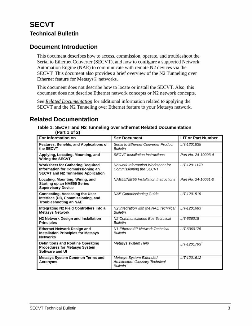
Related Documentation Table 1: SECVT and N2 Tunneling over Ethernet Related Documentation
(Part 1 of 2)For Information on See Document LIT or Part NFeatures, Benefits, and Applications of the SECVT
Serial to Ethernet Converter Product Bulletin
LIT-1201835
Applying, Locating, Mounting, and Wiring the SECVT
SECVT Installation Instructions Part No. 24-10
Worksheet for Gathering Required Information for Commissioning an SECVT and N2 Tunneling Application
Network Information Worksheet for Commissioning the SECVT
LIT-12011170
Locating, Mounting, Wiring, and Starting up an NAE55 Series Supervisory Device
NAE55/NIE55 Installation Instructions Part No. 24-10
Connecting, Accessing the User Interface (UI), Commissioning, and Troubleshooting an NAE
NAE Commissioning Guide LIT-1201519
Integrating N2 Field Controllers into a Metasys Network
N2 Integration with the NAE Technical Bulletin
LIT-1201683
N2 Network Design and Installation Principles
N2 Communications Bus Technical Bulletin
LIT-636018
Ethernet Network Design and Installation Principles for Metasys Networks
N1 Ethernet/IP Network Technical Bulletin
LIT-6360175
Definitions and Routine Operating Procedures for Metasys System Software and UI
Metasys system Help LIT-12017931
Metasys System Common Terms and Acronyms
Metasys System Extended Architecture Glossary Technical Bulletin
LIT-1201612
SECVT Technical Bulletin 3

umber
Using the System Configuration Tool (SCT) Software, Creating, Editing, and Downloading Archive DatabasesSCT Technical Bulletin LIT-1201534
Using HVAC PRO and Pass Though to View and Diagnose N2 Device Status
Using HVAC PRO Software in Pass Through Mode chapter in the HVAC Pro User’s Guide
LIT-63750402
General Network and Information Technology (IT) Definitions, Concepts, Recommendations, and Requirements
Network and IT Guidance for the BAS Professional Technical Bulletin
LIT-12011279
1. This LIT number represents a print friendly version of the Help.
Table 1: SECVT and N2 Tunneling over Ethernet Related Documentation (Part 2 of 2)
For Information on See Document LIT or Part N
SECVT Technical Bulletin4

Commissioning an SECVT Quick Start Guide
Figure 1: Commissioning an SECVT andN2 Tunneling Application Quick Start Guide
SECVT Technical Bulletin 5

E and TU
NN
EL_O
VERV
IEW
rs
2 Dataffic Over485 Bus
SECVT and N2 Tunneling OverviewThe SECVT, in conjunction with a supported NAE, enables N2 Tunneling over Ethernet on Metasys networks. N2 Tunneling increases N2 application flexibility, allows you to integrate remote N2 devices into the Metasys network, and reduces the need for hardwired RS485 protocol N2 Buses. See Serial to Ethernet Converter (SECVT) and Supported NAEs for more information on the SECVT and the supported NAE models.
The SECVT and the supported NAEs are designed to convert N2 protocol data and tunnel the converted data over Ethernet networks. Figure 2 shows a simple Metasys network with remote N2 devices communicating with a supported NAE over a Local Area Network (LAN).
You can apply N2 Tunneling to almost all Ethernet LANs. You can also apply N2 Tunneling to Wide Area Networks (WANs) that meet N2 Tunneling performance guidelines. See N2 Tunneling and Network Performance.
N2 TunnelingN2 Tunneling enables remote N2 field devices to exchange N2 data with supported NAEs across Ethernet networks. N2 Tunneling eliminates the need for a dedicated hardwired N2 Bus between the remote N2 devices and the supported NAE. The SECVT and a supported NAE enable N2 Tunneling over Ethernet.
N2 Tunneling is accomplished by packaging the N2 protocol data in Universal Datagram Protocol (UDP) packets, which makes the N2 data appear on the network as Ethernet data. Supported devices (SECVTs and NAEs), on either end of the tunneled transmission, convert N2 data to UDP packets and UDP packets back to N2 data.
Figure 2: Simple Metasys Network with N2 Devices Hardwired to a Supported NARemote N2 Field Devices Tunneled over Ethernet via an SECVT to the NAE
Internet
Firewall
Web Browseron a Desktop
Computer
EthernetNetwork
Web Browseron a Computer
NAE5512or
NAE5513 SECVT
N2 FieldControllers
N2 Data Tunneledover Ethernet
RemoteN2 Field
ControlleN2 Data
Traffic OverRS-485 Bus
NTraRS-
SECVT Technical Bulletin6

ieldice 7
Fig:
N2_
TUN
NL_
SCH
M
N2 Tunneling on a Metasys network is virtually transparent to the user. Procedures for accessing, configuring, controlling, and monitoring N2 field devices via an NAE are the same for tunneled N2 devices and N2 devices hardwired to the NAE N2 network trunk. Figure 3 shows a simple N2 Tunneling application and the relationship between tunneled N2 devices, hardwired N2 devices, and the NAE N2 trunks.
Serial to Ethernet Converter (SECVT)The SECVT is designed to convert serial N2 protocol data to UDP packets and tunnel the N2 data across Ethernet networks to supported NAE supervisory devices. The SECVT also receives N2 data tunneled as UDP packets from the assigned NAE. The SECVT then converts the UDP packets back to N2 data and routes the N2 data on to the appropriate N2 device on the SECVT N2 Bus.
The SECVT is compliant with Ethernet standards and designed to operate on 10 Mb or 100 Mb Ethernet networks.
You can connect up to 32 N2 devices in an N2 device cluster on the SECVT N2 Bus. Simple N2 device clusters are shown in Figure 3. The SECVT and N2 Tunneling over Ethernet feature do not affect the N2 device limits for supported NAE models. See Table 2.
The number of SECVTs that can be associated to an N2 trunk is limited by the number of N2 devices mapped to that N2 trunk. For example, an N2 trunk on a supported NAE supports up to 100 N2 devices; therefore, up to 100 SECVTs, each connected to one N2 device, can be associated to an N2 trunk on a supported NAE that does not have any hardwired N2 devices connected to the N2 trunk.
Figure 3: Simplified N2 Tunneling over Ethernet ApplicationIllustrating the Association of N2 Devices to the NAE N2 Network Trunks
EthernetPort
FC APort
FC BPort
N2 Trunk 2N2 Trunk 1
N2 FieldDevice 1
N2 FieldDevice 8
N2 FieldDevice 5
N2 FieldDevice 4
N2 FieldDevice 6
N2 FDev
N2 FieldDevice 3
N2 FieldDevice 2
Remote N2 Device ClusterTunneled to N2 Trunk 1
Ethernet Network
RS-485 RS-485
RS-485
RS-485
Remote N2 DeviceTunneled to N2 Trunk 2
Standard N2 Field TrunksN2 Field Devices 1, 6, 7, and 8 are mapped to N2 Trunk 1
N2 Field Devices 2, 3, 4, and 5 are mapped to N2 Trunk 2
SECVT SECVT
SECVT Technical Bulletin 7

Supported NAEsThe Network Automation Engine (NAE) is a Web-based supervisory device that monitors and controls Building Automation System (BAS) field controllers and devices on Metasys networks. The NAE also provides Web-based access to BAS network trunks, controllers, and field devices on the Metasys network.
Supported NAE models are designed to tunnel N2 data over Ethernet to and from remote N2 field devices via an SECVT. To apply N2 tunneling to a Metasys network, an NAE that supports tunneling must be installed on the network. Currently two NAE models support the N2 tunneling feature out-of-the-box: the MS-NAE5512-0 and MS-NAE5513-0 models.
You can upgrade non-tunneling NAE55 models (only) to supported N2 Tunneling models in the field by purchasing Part No. MS-NAETUNL-8 ToggleTunnel utility, which converts an NAE55 to an NAE55 model with the N2 Tunneling feature enabled.
The N2 trunk and device limits for supported NAE55 models are the same for hardwired N2 devices, tunneled N2 devices, or any combination of hardwired and tunneled N2 devices. See Table 2. The NAE55 object capacity can also limit the number of N2 devices in your N2 Tunneling application.
An NAE5512 or NAE5513 with Metasys Release 3.1 software supports two methods of Internet Protocol (IP) address assignment: static and Dynamic Host Configuration Protocol (DHCP).
Note: If you encounter communication issues, we recommend using static address assignment.
Ethernet Port
SEC
VT
1807.1
1275.0
582.3
N2 Bus Pluggable Terminal Block
MountingClips (3)
Restore DefaultsButton (Recessed)
End-of-Line (EOL)Switches
Figure 4: Serial to Ethernet Converter, Physical Featuresand Dimensions, mm (in.)
SECVT Technical Bulletin8

N2 Tunneling and Network PerformanceYour network’s performance and data capacity can limit N2 Tunneling applications on your network. The NAE and SECVT are compliant with Ethernet standards, and both devices can operate on 10 Mb or 100 Mb networks. N2 Tunneling is designed to operate on most LAN applications and on WAN applications that maintain certain network performance criteria. See Table 10 on page 33 for N2 Tunneling performance guidelines.
A network’s data capacity rarely limits N2 Tunneling applications. The N2 data transmission between an SECVT and an NAE consumes very little bandwidth, less than 0.5% of the usable bandwidth on a 10 Mbps Ethernet network.
The primary limiting factor on most N2 Tunneling applications is the time it takes for tunneled data packets to traverse the network (and network devices) between an SECVT and a supported NAE. Routers, firewalls, Network Address Translators (NATs), and other network devices can delay the transfer of tunneled packets. Significant packet delays may result in N2 devices periodically going offline to the supported NAE.
Note: If you are using static IP addresses, and your network uses NATs to communicate across the Internet, the NATs must provide static internal and external IP addresses. If you are using Dynamic Host Configuration Protocol (DHCP) to assign addresses to SECVTs that communicate across networks that use NAT, your DHCP server should be configured to always allocate the exact same IP address to the SECVT's MAC addresses. This configuration makes these SECVTs behave as if they have static IP addresses, although they have DHCP addresses (sometimes called Dynamically Assigned, Statically allocated addresses from a DHCP server). Dynamic network address translation may result in N2 device offline conditions.
Table 2: N2 Tunneling Features and Devices on NAE55 ModelsN2 Tunneling Features and Devices
Standard Non-TunnelingNAE55 Models
N2 Tunneling over Ethernet with SECVTs
Number of N2 Trunks 2 2
Number of N2 Trunks That Support N2 Tunneling
0 2
Number of N2 Devices Supported on an N2 Trunk
Up to 100(Hardwired to FC Bus Only)
Up to 100(Hardwired and/or Tunneled over Ethernet)
Number of Converters Supported on an N2 Trunk
Up to 100
Number of N2 Devices Supported on a Converter N2 Bus Cluster
N/A Up to 32
Simultaneous Support of N2 Devices That Are Hardwired and Tunneled over Ethernet
No Yes
Simultaneous Support of N2 Devices That Are Hardwired and Tunneled over Ethernet
No Yes
SECVT Technical Bulletin 9

On LAN applications, tunneled packets typically traverse only in-house routers. Since the delay on in-house routers on a LAN is usually a few milliseconds, the N2 data transfer is unaffected.
On WAN applications, the tunneled packets may have to traverse firewalls, NATs, and third-party routers, all of which can significantly delay N2 data transfer causing the transfer time to exceed the required message timeout value.
Before installing the devices on large LANs and all WANs, we recommend testing the message cycle time between the subnet on which the NAE resides and the subnets on which any SECVTs reside. Install the NAE and SECVT on your network on subnets that exhibit the shortest message cycle times. A successful N2 Tunneling application requires a total message cycle time of less than 1,000 ms between the NAE and SECVT. See Determining Network Performance for more information on testing your network.
We also recommend providing the customer’s network administrator or IT department with a copy of the Network Information Worksheet for Commissioning the SECVT (LIT-12011170). The worksheet is used to determine network performance and the viability of an N2 tunneling application on the customer network. The worksheet is also used to gather the IP network address information required for commissioning and connecting SECVTs on the customer’s network.
The frequency of offline conditions on N2 Tunneling applications increases as the transfer time between the NAE and SECVT increases. When applying the N2 Tunneling feature to network applications that approach the N2 Tunneling performance limits, we recommend using only those N2 devices and applications that can operate independently of the NAE and the Metasys system. See Table 10 on page 33.
After your N2 Tunneling application is set up, fluctuating network traffic loads and changes to the network may adversely affect N2 data transfer time. Retest your N2 Tunneling application to verify the total message cycle time whenever N2 devices go offline.
SECVT User InterfaceThe SECVT has a browser-based UI for commissioning and monitoring the Converter. Access the SECVT UI using Microsoft® Internet Explorer Version 6.0 or later. See Detailed Procedures for more information on accessing the SECVT UI.
UI Status PageThe SECVT UI Status page provides information that identifies the Converter, the selected RS485 baud rate, and the SECVT firmware revision. The Status page also provides a log of events.
There are two tabs on the SECVT Status page:
• The About tab provides information about the SECVT identity on the network and the firmware revision (Figure 5).
SECVT Technical Bulletin10

• The Events tab provides a list of the 200 most recent SECVT reboots or power losses. After 200 events are recorded, the oldest event is deleted when a new event is added to the list.
The SECVT Reboot button is also found on the Status page (Figure 5). Clicking Reboot opens a reboot confirmation page. Confirming the reboot cycles the power to the SECVT, which resets the Converter date and time to the default setting. You must reenter the date and time values after rebooting the SECVT. See Setting the SECVT Date and Time Values. A complete SECVT reboot takes less than 1 minute.
UI Configuration PageCommission the SECVT for operation in your application by selecting or entering the appropriate attribute values on the tabs on the Configuration page. Figure 6 shows the RS485 tab (in edit mode) on the Configuration page.
There are four tabs on the SECVT Configuration page:
• The RS485 tab establishes the RS485 and N2 Bus parameters.
• The Network tab establishes the SECVT host name, IP address, and network routing information for the Ethernet network.
• The Administration tab establishes the logon passwords.
• The Time tab establishes the SECVT time and date.
Figure 5: About Tab on the SECVT Status Page
Converter Reboot Button
VER_1_0
SECVT Technical Bulletin 11

Detailed Procedures
Commissioning an N2 Tunneling Application OverviewCommissioning an N2 Tunneling application begins with good planning and design. Figure 1 is a flowchart of steps for commissioning an SECVT and supported NAE for N2 Tunneling applications.
An N2 Tunneling application requires very little bandwidth on the network, but network firewalls, routers, switches, and other network devices may impede N2 messages and limit your tunneling application. See N2 Tunneling and Network Performance.
Before installing the SECVT on WAN applications, we strongly recommend testing the network route and determining the response time between the subnet on which the supported NAE resides and the subnet on which any SECVTs are to reside. See Determining Network Performance for procedures on testing your network application.
To commission an N2 Tunneling application:
1. Obtain the required attribute values for commissioning the SECVT, the supported NAE, and the N2 Tunneling application from your customer’s network administrator or IT department.
Figure 6: RS485 Tab on the Configuration Page
SECVT Technical Bulletin12

To gather the network information required for commissioning an SECVT and N2 tunneling over Ethernet application, provide the Network Information Worksheet for Commissioning the SECVT (LIT-12011170) to the customer’s network administrator or IT department.
If you are using static IP addresses, see DNS Implementation Considerations. Required attribute values include:
• a unique IP address for each SECVT to be commissioned
• the subnet mask and default gateway for each SECVT
• the required UDP port address (if the default port addresses cannot be used)
• the unique N2 device addresses for all N2 devices in the device cluster on the SECVT N2 Bus
• the N2 objects required to add the N2 devices to the Metasys site database
If you are using DHCP IP addresses, see DHCP Implementation Considerations. Required attribute values include:
• the host name of each SECVT to be commissioned
• the default gateway for each SECVT
• the required UDP port address (if the default port addresses cannot be used)
• the unique N2 device addresses for all N2 devices in the device cluster on the SECVT N2 Bus
• the N2 objects required to add the N2 devices to the Metasys site database
Note: To use DHCP addressing, an NAE5512 or NAE5513 with Metasys Release 3.1 software is required.
2. Obtain the SECVTs and supported NAEs for your application. Commission each SECVT (one at a time) before installing it or connecting it to the network. If you are using static IP addresses, record the new IP address for each SECVT (on the labels provided) as you commission the devices. You can commission and configure the supported NAE on the network or before you install the NAE on the network.
3. Install the supported NAE and connect it to the network (if it is not already installed and connected). Connect the SECVT at the appropriate location on the network. Install the N2 devices, and connect them to the SECVT N2 Bus. See Related Documentation for references to information on configuring N2 devices and an N2 Bus.
4. If your N2 application experiences N2 device offline conditions, determine the network performance. See Determining Network Performance for performance guidelines and procedures for testing the network.
SECVT Technical Bulletin 13

Guidelines for Commissioning an SECVT• Always commission the SECVT before installing it on the network.
• All SECVTs are shipped with the same default IP address (http://169.254.0.10). If you are commissioning more than one SECVT, apply power to, connect to, and commission only one Converter at a time.
• Clicking Save in the SECVT UI saves the changes on the displayed tab to temporary (volatile) memory. Clicking Apply All Changes saves all temporarily saved changes to nonvolatile memory and implements the changes. See Navigating the SECVT UI for more information.
• Do not click Apply All Changes on the Configuration page until all new attribute values in all of the tabs are entered correctly. After you enter the new Network tab values, clicking Apply All Changes changes the SECVT IP address and breaks the Ethernet connection between your computer and the SECVT. See Navigating the SECVT UI for more information.
• If the connection between your computer and the SECVT is lost during commissioning, and you cannot reestablish the connection, you can press the Restore Defaults button to restore the original SECVT default values. Press and hold the Restore Defaults button for at least 5 seconds. The red FAULT LED should blink four times. Then the SECVT reboots and restores the attributes to the original default values, including the default IP address you used to connect.
Note: After restoring the default values, you have to reenter all of the values you changed prior to pressing the Restore Defaults button.
• The values entered into the Date and Time fields do not advance until you Apply All Changes. To ensure that the date and time displayed on the SECVT are synchronized with real time, you should set the date and time after commissioning and installing the SECVT on the network.
• Set the End-of-Line (EOL) switches to the proper position on the SECVT and on any other N2 device on the N2 Bus. Refer to the SECVT Installation Instructions (Part No. 24-10093-4) for information on setting the SECVT EOL switches.
• When an SECVT is applied to the network and powered on for the first time, it may take up to 5 minutes for the network to locate the new SECVT and register the new IP address and Media Access Control (MAC) address. The SECVT does not operate as intended until these addresses are registered with the appropriate devices on the network.
Connecting to, Accessing, and Navigating the SECVT UI
SECVT Technical Bulletin14

RequirementsYou need the following items to connect to an SECVT, access an SECVT Web UI, and commission the SECVT for network operation:
• an SECVT
• a 24 VAC, 20 VA minimum, Class 2 power supply
• a computer with an RJ45 Ethernet port and Internet Explorer Version 6.0
• an Ethernet cable (patch cable or crossover cable)
Note: The SECVT is designed to be connected directly to a computer Ethernet port during the commissioning procedure. The SECVT detects the cable polarity at the Ethernet port and automatically configures itself to communicate with the computer via a patch cable or a crossover cable. A hub or switch is not required.
DNS Implementation Considerations
The Domain Name Server (DNS) infrastructure must be configured to do the following:
• The Metasys server and/or Metasys engine and Metasys DHCP supported devices (SWECVT, WRS-RTN Many-to-One Receivers) must be defined in the same DNS domain.
• The Metasys server and/or Metasys engine and Metasys DHCP supported devices (SWECVT, WRS-RTN Many-to-One Receivers) require DNS servers defined to resolve hosts in the domain which they are in.
• We recommend that the Metasys server and/or engine and Metasys DHCP supported devices (SWECVT, WRS-RTN Many-to-One Receivers) be in a separate Virtual Local Area Network (VLAN) from all other devices at the customer’s site.
• If the DNS server and the Metasys server and/or Metasys engine are in different networks (VLANs), routing must be available between networks.
DHCP Implementation Considerations
For Metasys devices to function properly in a DHCP implementation, the DHCP servers must support dynamic DNS. The DHCP infrastructure must be configured to do the following:
• The DHCP server must create an A record in the defined DNS domain upon handing a lease to a Metasys device. Optionally, you can configure the DHCP server to update the PTR (pointer) record of the Metasys DHCP supported device in the reverse zone DNS domain.
• The domain for DNS updates must be included in the DHCP server configuration. The Metasys DHCP supported device does not specify the domain.
SECVT Technical Bulletin 15

• The Metasys server and/or Metasys engine and the Metasys DHCP supported devices (SECVT, WRS-RTN Many-to-One Receivers) all must be in the same DNS domain.
• We recommend that the Metasys server and/or Metasys engine and the Metasys DHCP supported devices (SECVT, WRS-RTN Many-to-One Receivers) be in a separate VLAN from all other devices at the customer’s site.
• If the DNS server, Metasys server, Metasys engine, and/or Metasys DHCP supported devices (SECVT, WRS-RTN Many-to-One Receivers) are in different networks (VLANs), ensure that routing is available between networks and that a proper router is passed in the DHCP lease.
• If the DHCP server is not is the same VLAN as the Metasys devices, enable DHCP forwarding to the proper DHCP server on the VLANs on which the Metasys devices are located.
Metasys devices require that you configure the following DHCP options in the DHCP server in addition to the IP address and subnet mask:
To gather the network information required for commissioning an SECVT and N2 tunneling over Ethernet application, provide the Network Information Worksheet for Commissioning the SECVT (LIT-12011170) to the customer’s network administrator or IT department.
Connecting to the SECVT and Accessing the UI
To connect to the SECVT and access the UI:
1. Turn on your computer, and connect the SECVT to the computer with an Ethernet cable.
2. Power on the SECVT and allow it to go through its startup sequence.
Note: When the SECVT is powered On, it goes through a startup sequence. See SECVT LED Test Sequence at Startup for more information.
3. In the Start menu on your computer, click Settings > Control Panel > Networks and Dial Up to check the status and enable the local Ethernet network.
4. In the General menu dialog box, scroll to and click Internet Protocol(TCP/IP) to highlight the text and click Properties. Ensure that a valid IP address and subnet mask are assigned to the computer for the Ethernet network connection to the SECVT. Valid IP addresses and subnet mask are:
• IP Address = 169.254.0.x (where x = any value between 2 and 255 other than 10)
• Subnet Mask = 255.255.255.0
Table 3: DHCP OptionsOption DescriptionOption 003 Router
Option 006 DNS Servers
Option 015 DNS Domain Name
SECVT Technical Bulletin16

Note: Record the original network settings and IP address for your computer before changing the setting values, so you can restore the original values after you have commissioned the SECVT.
5. If necessary, enter a valid IP address and subnet mask in the Properties dialog box.
6. Click OK.
7. With the network enabled, start Internet Explorer. Type the SECVT default IP address (http://169.254.0.10) into the Address bar and press Enter. The SECVT logon dialog box appears (Figure 7).
8. In the logon dialog box, type the default User name (admin) and Password (admin). An opening flash page (Figure 8) appears for approximately 5 seconds, and then the SECVT UI Home page opens (Figure 9).
Note: The User name guest and the Password guest are available for SECVT users who need to view the UI but do not need to edit any of the values in the SECVT UI.
You should be logged on to the SECVT and ready to navigate the Web UI.
Figure 7: SECVT UI Logon Dialog Box
Default Password is admin
SECVT Technical Bulletin 17

Figure 8: SECVT UI Opening Flash Page
Figure 9: SECVT UI Home Page
SECVT Technical Bulletin18

Navigating the SECVT UIYou navigate the SECVT UI just like a typical Web site.
Page links are on the left side of the page. From the Home page, the Page links go to the Configuration and Status pages. Click a tab to open the associated property sheet.
Figure 10 shows a typical SECVT UI screen, the RS-485 tab (in edit mode).
Page Command buttons (Figure 10) are above the Attribute and Value tables on each of the Configuration tabs:
• The Edit button opens an editable screen.
Note: All tabs and page links on the editable screen are disabled, and only the Save, Reset, and Cancel page command buttons are active.
• The Save button saves the edited attribute values on the screen to temporary memory (Figure 10).
Note: After you click Save, a command in red type appears just below the tabs stating that you must click Apply All Changes to save the edited values to permanent memory and implement the changes on the SECVT (Figure 11). Do not click Apply All Changes until you have entered, saved, and reviewed all of the required attribute values on all Configuration tabs in the SECVT UI.
Figure 10: RS485 Tab on the Configuration Page
SECVT UIPage Links
Page Command Buttons
Active Tab
Editable Values: Selectthe Required Value
SECVT Technical Bulletin 19

• The Reset button resets the attribute values on the screen to the last saved values (Figure 10).
• The Cancel button cancels all changes on the screen (Figure 10).
Two Changes Command buttons are on the lower left of the Configuration page (Figure 11) whenever you are in a Tab screen:
• The Apply All Changes button saves (to nonvolatile memory) all of the temporary (volatile) changes that were saved on the various tabs and implements the changes on the SECVT.
Note: Do not click Apply All Changes until after you have edited and reviewed all required values in the SECVT UI. Clicking Apply All Changes saves and implements the edited values on the SECVT, including the new IP address. When the SECVT IP address is changed, the network connection to your computer is broken.
• The Cancel All Changes button cancels all of the temporary (volatile) values that were changed and (temporarily) saved on the various tabs and reverts the values to the previously saved (nonvolatile) values.
Figure 11: Network Tab on the Configuration Pagewith the Apply All Changes Command (in Red)
Changes Command Buttons
Apply All Changes Command
SECVT Technical Bulletin20

Checking the SECVT StatusThe SECVT UI has two tabs on the Status page that provide information about the Converter. See UI Status Page for more information.
Note: You cannot edit any of the attribute values while on the Status page. Some of the attribute values on the Status page can be changed on the Configuration page. Some of the values (such as the MAC address) are fixed. Some of the values (like the software version) can be changed by updating the software. Any attribute value changes appear as new value in the Status page tabs after you Apply All Changes.
To check the tabs on the Status page:
1. From anywhere in the SECVT UI, click the Status page link, and the Status page About tab appears (Figure 5).
2. Click the Events tab to go to the Events tab.
Commissioning an SECVT
Setting the Serial Network Attributes on the RS485 Tab
For the SECVT to communicate with the N2 field devices on its N2 Bus, you must configure the RS485 serial network attributes on the Configuration page RS485 tab.
Note: Only the N2 Protocol value is available on the SECVT in this release. Additional protocols will be available in future releases of the Metasys system extended architecture.
To set the serial (N2) network attributes on the RS485 tab:
1. In the SECVT UI, click Configuration. The Configuration page appears. Click the RS485 tab, and the RS485 tab opens.
SECVT Technical Bulletin 21

y other baud
2. Click Edit (Figure 12).
3. Select the appropriate values for the N2 field devices connected to the SECVT according to Table 4.
4. Review the new values and then click Save to save the new values to temporary memory.
Table 4: RS485 Tab Attributes and ValuesAttribute Attribute Description Default
ValueValid Values
Protocol Select the appropriate protocol for the RS-485 field bus.Note: N2 is currently the only usable value for the
Protocol attribute.
N2 N2
Baud Rate Select the Protocol first, then select the appropriate baud from the drop-down menu.Note: 9600 is currently the only available value
for the Baud Rate attribute.
9600 N2 baud is 9600(Do not select anfor N2 protocol.)
Data Bits Select the data bits setting from the drop-down list. 8 7, 8
Parity Select the parity setting from the drop-down list. No No, Even, Odd
Stop Bits Select the stop bits setting from the drop-down list. 1 1, 2
Figure 12: RS485 Tab on the Configuration Page
SECVT Technical Bulletin22

Note: Click Apply All Changes on the Configuration page to save all of the edited values to nonvolatile memory. Clicking Apply All Changes may break the Ethernet connection between your computer and the SECVT. Do not click Apply All Changes until you have edited and reviewed all the required values for the SECVT setup.
5. Open the next tab you need to edit.
Setting the Ethernet Network Attributes on the Network TabFor the SECVT to communicate over the Ethernet network, enter the SECVT host name and other network attributes on the Configuration page Network tab (Figure 13).
To gather the network information required for commissioning an SECVT and N2 tunneling over Ethernet application, provide the Network Information Worksheet for Commissioning the SECVT (LIT-12011170) to the customer’s network administrator or IT department.
To establish or change the Ethernet network attribute values on the Network tab:
1. In the SECVT UI, click Configuration. The Configuration Page appears. (By default the Configuration page opens with the RS485 tab displayed.) Click the Network tab and the Network tab opens.
2. Click Edit to open the Network tab (Figure 13).
Figure 13: Network Tab
SECVT Technical Bulletin 23

aximum ly rs, dashes
sion 4)
sion 4)
sion 4)
3. Select or type the appropriate attribute values for the Ethernet network according to Table 5.
4. Review the new values, and then click Save to save the new values on the Network tab to temporary memory.
Note: You must click Apply All Changes on the Configuration page to save all of the edited values to nonvolatile memory, but do not click Apply All Changes until you have edited and reviewed all the required values for the SECVT setup. Clicking Apply All Changes breaks the Ethernet connection between your computer and the SECVT.
5. If you are using static IP addresses, record the new IP address on the SECVT label. If you are using DHCP addresses, record the host name on the SECVT label.
Note: The host name may contain a maximum of 15 characters and may comprise alphabet letters, numbers, and dashes.
6. Open the next tab you need to edit.
Changing the SECVT Logon PasswordsThe SECVT has three User names for logging on to the UI. The User name value cannot be changed. The three Password fields have default values. You can change the default Password values and establish new Passwords for logging on to the SECVTs in your application.
The UI logon feature also provides two levels of privilege when accessing the UI:
• User privilege allows the user to check the SECVT status (only). There is one User name for user privileges: guest.
• Administrator privilege allows the user to check the SECVT status and change all of the attribute values. There are two User names for administrator privileges: admin and manager.
Table 5: Network Tab Attributes and ValuesAttribute Attribute Description Default Value Valid ValuesHost Name If you are using DHCP IP addresses, type the
host name of the SECVT.Converter1 15 character m
comprising onalphabet lettenumbers, and
DHCP Enabled Select Yes if you are using dynamic IP addresses, select No to disable DHCP.
No Yes or No
IP Address (Converter)
If you are using static IP addresses, type the IP address assigned to the SECVT by your IT department.
169.254.0.10 x.x.x.x (IP Ver
UDP Port Number
Type the UDP Port number on the supported NAE that the SECVT sent UDP packets to.
4096 1024 to 65535
Subnet Mask Type the subnet mask address that the SECVT resides on.
255.255.255.0 x.x.x.x (IP Ver
Default Gateway
Type the default gateway address. 169.254.0.1 x.x.x.x (IP Ver
SECVT Technical Bulletin24

fault Valuemin
nager
est
Table 6 describes the attributes and values on the Administration tab.
To change the SECVT Password values:
1. Access the SECVT UI, go to the Configuration page, and click the Administration tab. The Administration tab opens.
2. Click Change Password (Figure 14).
3. Type the current password values where appropriate, and type your new password in the New Password field. Then type your new password again in the Reenter New Password field to confirm.
4. Click Save to save the new values to temporary memory.
Note: You must click Apply All Changes on the Configuration page to save all of the temporarily save values to nonvolatile memory, but do not click Apply All Changes until you have edited and reviewed all the required values for the SECVT setup. Clicking Apply All Changes breaks Ethernet connection between your computer and the SECVT.
5. Record the new Password values and store them in an appropriate place.
Table 6: Administration Tab Attributes and ValuesAttribute Attribute Description Deadmin Logon password for administrative privileges (customer or on-site administrator). ad
manager Logon password for administrative privileges (Johnson Controls® administrator). ma
guest Logon password for user privileges (all other users). gu
Figure 14: Administration Tab on the Configuration Page
SECVT Technical Bulletin 25

Setting the SECVT Date and Time ValuesThe SECVT uses the date and time to log events to the Events Log.
Note: To ensure that the SECVT date and time are synchronized with real time, you should set the date and time after the SECVT is commissioned and installed on the production network.
The Time and Date values revert to the factory default settings (01-01-1970, 12:00AM) whenever the SECVT loses power or is rebooted, or whenever the Restore Defaults button is pressed.
To set Date and Time values for the SECVT:
1. Connect your computer to the network to which the SECVT is connected. Start Internet Explorer on your computer. If you are using static IP addresses, type the (new) SECVT IP address into the Address bar. If you are using DHCP IP addresses, type the host name into the Address bar. Press Enter and log on to the SECVT.
2. Access the SECVT UI, go to the Configuration page, and click the Time tab.
3. Click Edit (Figure 15).
4. Enter the current date and time values.
5. Click Save to save the new values to temporary memory.
Figure 15: Time Tab on the Configuration Page
SECVT Technical Bulletin26

6. Click Apply All Changes immediately to apply and implement the new date and time values.
Note: The values entered into the Date and Time fields do not advance until you Apply All Changes.
7. Close the SECVT UI and disconnect your computer from the network.
Configuring the NAE for N2 Tunneling over EthernetTo apply N2 Tunneling over Ethernet to your Metasys network, a supported NAE must be on the network. If you are using a static IP address, you must map the SECVT IP address and the tunneled N2 devices to an N2 trunk on the supported NAE. If you are using a DHCP IP address, enter a host name for the SECVT. The host name may contain a maximum of 15 characters and may comprise alphabet letters, numbers, and dashes.
Note: To use DHCP addressing, an NAE5512 or NAE5513 with Metasys Release 3.1 software is required.
Each of the N2 devices mapped to the NAE N2 Trunk (tunneled and hardwired) must be assigned a unique N2 address so that the NAE can identify and communicate with the individual N2 devices.
Install, commission, and configure the supported NAE per instructions. See Related Documentation for references to information on installing, commissioning, and configuring an NAE.
Note: You can configure the NAE online or offline using the System Configuration Tool (SCT). We recommended that you configure the NAE offline in SCT and download the configured archive database to the SCT. See Related Documentation for references to information on creating, editing, and downloading archive databases.
Requirements
You need the following items to configure a supported NAE to tunnel to N2 devices:
• a computer with Internet Explorer Version 6.0 or later (and with SCT to configure the supported NAE offline)
• a commissioned and configured NAE that supports the N2 Tunneling feature. See Supported NAEs. The NAE must have the Device objects for the tunneled N2 devices configured in the NAE archive database.
Note: The NAE Auto-Discovery feature cannot find N2 devices that are tunneled to the NAE. The NAE must contain a database with the device objects for the N2 devices that are tunneled to the NAE.
• a fully commissioned and installed SECVT with a 24 VAC, 20 VA minimum Class 2 power supply
SECVT Technical Bulletin 27

• one or more N2 field devices wired in an N2 device cluster to the SECVT N2 Bus. (See Table 2 for information on N2 device limits for N2 network trunks on tunneling applications.) Each device mapped to an N2 trunk must have a unique N2 Address.
Configuring the NAE to Communicate with Tunneled N2 DevicesTo configure the supported NAE to communicate with tunneled N2 devices:
1. Log on to the supported NAE.
2. Drag and drop the target N2 Trunk into the Display panel. Click on the N2 Network Hardware tab.
3. Select the Advanced radio button, and then click Edit (Figure 16).
Figure 16: N2 Network Advanced Hardware Tab
SECVT Technical Bulletin28

4. Set the attribute values in the N2 Network Hardware Advanced tab according to Table 7.
5. Navigate to the N2 Device object for an N2 device that is connected to the target SECVT N2 Bus and click the Hardware tab (Figure 17).
Table 7: N2 Network Advanced Hardware TabAttribute ValueTrunk Number N2 trunk number 1 (= FC A port)
N2 trunk number 2 (= FC B port)Select the N2 trunk you are tunneling N2 devices to. (Hardwire N2 to the FC port associated with the N2 trunk.)
UDP Port Type in a UDP port number (between 1024 to 65535) to specify the UDP port where the NAE receives tunneled N2 data. This number must equal the port number entered on the Network tab on the target SECVT.4096 is the recommended UDP port number for N2 trunk number 1 on the NAE.4097 is the recommended UDP port number for N2 trunk number 2 on the NAE.
Retries 5 (Range is 3 to 8)
Poll Delay 100 (Range is 100 to 1,000 ms)
Message Timeout 1750 (Range 250 to 3,000 ms)See Determining Network Performance.
Diagnostic Messages False
Figure 17: An N2 Device Hardware Tab
SECVT IP Address forStatic addressing
Unique N2 Addressfor N2 Field Device
SECVT host hame for DHCP addressing
SECVT Technical Bulletin 29
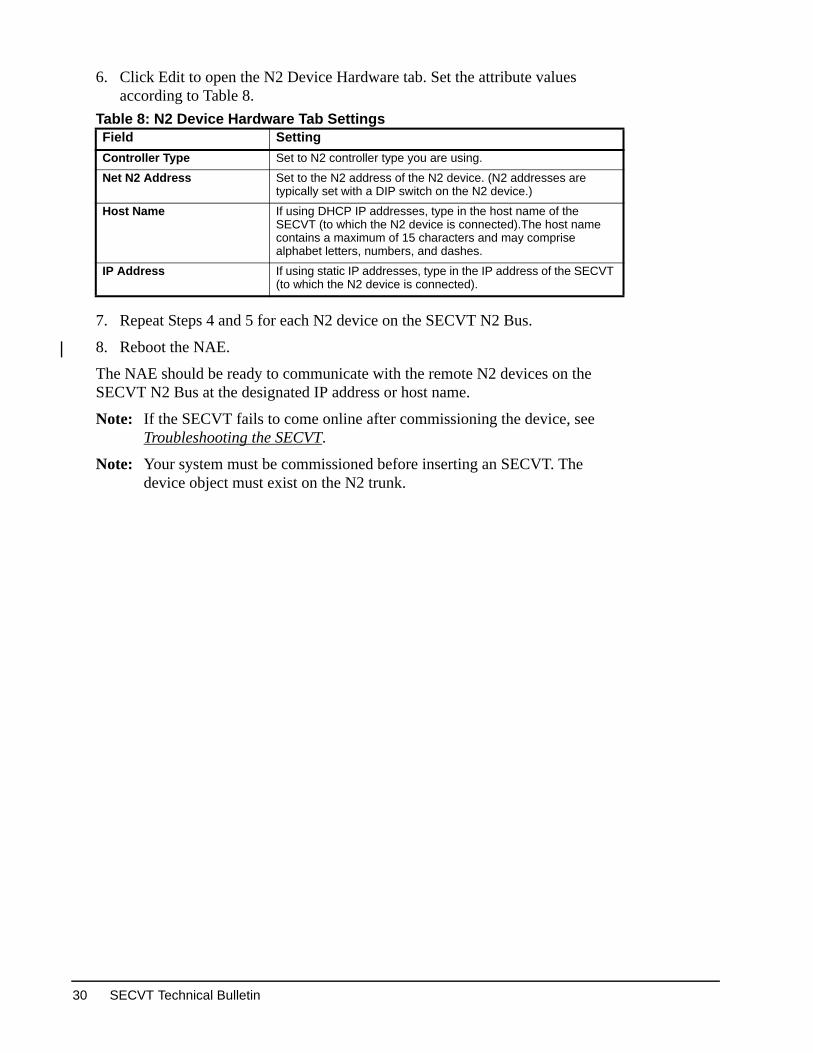
6. Click Edit to open the N2 Device Hardware tab. Set the attribute values according to Table 8.
7. Repeat Steps 4 and 5 for each N2 device on the SECVT N2 Bus.
8. Reboot the NAE.
The NAE should be ready to communicate with the remote N2 devices on the SECVT N2 Bus at the designated IP address or host name.
Note: If the SECVT fails to come online after commissioning the device, see Troubleshooting the SECVT.
Note: Your system must be commissioned before inserting an SECVT. The device object must exist on the N2 trunk.
Table 8: N2 Device Hardware Tab SettingsField SettingController Type Set to N2 controller type you are using.
Net N2 Address Set to the N2 address of the N2 device. (N2 addresses are typically set with a DIP switch on the N2 device.)
Host Name If using DHCP IP addresses, type in the host name of the SECVT (to which the N2 device is connected).The host name contains a maximum of 15 characters and may comprise alphabet letters, numbers, and dashes.
IP Address If using static IP addresses, type in the IP address of the SECVT (to which the N2 device is connected).
SECVT Technical Bulletin30

ting and transmission n times.
Mbps.
0 Mbps.
on. Ethernet
ead Ethernet
Troubleshooting the SECVTThis section of this document provides information for troubleshooting an SECVT, and troubleshooting SECVT communication with the supported NAE and the N2 devices. This section also provides information on how to determine network performance related to N2 Tunneling. This section does not describe how to troubleshoot NAEs, Ethernet networks, or N2 networks. See Related Documentation for references to information about NAEs, Ethernet networks, and N2 networks.
SECVT LED Status IndicatorsThe SECVT provides Light-Emitting Diode (LED) status indicators that are useful for troubleshooting the SECVT.
The SECVT has six LEDs that provide status information.
SECVT LED Test Sequence at StartupDuring startup, the SECVT automatically initiates an LED test sequence to verify the operational status of the LEDs. Immediately after connecting supply power, the following LED lighting sequence occurs:
1. The POWER LED lights, and then all of the remaining LEDs light.
2. The POWER LED remains lit while all other LEDs go to Normal operation as indicated in Table 9.
Note: If the LEDs do not go to normal operation, use Table 9 to diagnose the problem.
Table 9: SECVT LED Designations, Descriptions, and IndicationsLED Label LED Color Normal Descriptions/Other ConditionsPOWER Green On Steady On Steady = Power is on.
Off = Power is off.
FAULT Red Off Off Steady = No FaultsOn Steady = Device FaultBlink = Ethernet Network Fault
N2 BUS Green Flicker Flicker = Normal communications; N2 port is transmitreceiving data. Flickers are generally in sync with databut should not be used to indicate specific transmissioOff Steady = No N2 traffic on the SECVT N2 Bus.
10 Link1
1. Only one LINK LED is on at a time.
Green -- On Steady = Ethernet connection is established at 10
100 Link1 Green -- On Steady = Ethernet connection is established at 10
Ethernet Green Flicker Flicker = Data is transferring on the Ethernet connectitraffic is general traffic (may not be for the SECVT).Off Steady = No Ethernet traffic, probably indicates a dnetwork or bad Ethernet connection.
SECVT Technical Bulletin 31

Determining Network PerformanceNetwork performance determines the viability of your N2 Tunneling application. See N2 Tunneling and Network Performance for more information. The following tests help to determine your network’s performance.
These tests should be performed prior to installation on all WAN applications. These tests should also be performed after changes are made to your network or whenever your N2 application exhibits an increase in N2 device offline conditions.
Refer to the Microsoft Windows® Help system on your computer for more information about and examples of these tests.
Determining the N2 Message Path Using the Trace Routing Test
Use the trace routing test to determine the devices or nodes that tunneled N2 data must traverse between the subnet on which the supported NAE is to reside and the subnets on which any associated SECVTs are to reside. The trace routing test also determines the time (in milliseconds) for a message to pass between devices along the route. The test can be used to determine which network devices are impeding the tunneled messages. Search for tracert command in Windows Help for more information.
Note: Do not use the trace route test result times to determine network performance in Table 10. Use the PATHPING test result times to determine network performance.
To perform this test, you need to know the IP address (or host name) of a device on the target subnet.
To perform the trace routing test:
1. Connect your computer with an Ethernet cable to either the subnet on which the NAE is to reside or the subnet on which the SECVT are to reside.
2. Click Start > Run... to open the Run... dialog box.
3. Type cmd in the Run... dialog box and click OK to open a DOS window.
4. Type tracert (after C:\>) followed by a space and then the IP address of the target device on the target subnet.
5. Press Enter.
The trace route test sends several test messages from your computer to the target IP address and provides a tabulation of the resulting message delays between devices. Refer to Windows Help for more information on deciphering the trace route test results.
Determining the NAE Message Timeout Using the PATHPING TestUse the PATHPING test to verify that a device on the network can communicate with other devices on the network and to determine the message delay between the various devices that the message traverses on the network. Search for pathping command in Windows Help for more information.
SECVT Technical Bulletin32

Use the average total PATHPING time to determine the total message cycle time between an SECVT and the supported NAE. See Table 10.
To perform the PATHPING test, your computer must be configured to use Transfer Control Protocol/Internet Protocol (TCP/IP) protocol and at least one device (with an IP address) must be connected to the target subnet.
To perform the PATHPING test:
1. Connect your computer with an Ethernet cable to the subnet on which the NAE is to reside.
2. Click Start > Run... to open the Run... dialog box.
3. Type cmd in the Run... dialog box and click OK to open a DOS window.
4. Type pathping (after C:\>) followed by a space and then the IP address (or host name) of the target device on the subnet on which the SECVT is to reside.
5. Press Enter.
If you get a reply and test result times, your computer and the target device are communicating on the network.
If you do not get a reply, try to PATHPING your own computer IP address.
• If you can PATHPING your computer’s IP address, but not any other IP addresses, check the TCP/IP properties of the Ethernet connection on your computer and make sure the IP address is set to the same subnet as the NAE.
• If you do not get a reply from your computer’s IP address, make sure that any wireless connection is disabled and the Ethernet connection is enabled on your computer.
Table 10: Estimated N2 Tunneling Performance Based on PATHPING TestAverage Total PATHPING Time (ms)
Total Message Cycle Time(ms)
N2 Tunneling Application Performance
<25 <50 Excellent, no noticeable difference from a hardwired N2 Bus.
25-50 <100 Good, slight delays may be noticed on devices that display a user interface.
50-150 100-300 Acceptable, but recommended for N2 devices or N2 applications that can operate independently of the NAE and Metasys system.
150-500 300-1000 Application specific, recommended only for specialized N2 applications that can run independently of the NAE and Metasys system.
>500 >1000 Unacceptable, delays are too long, hardwire the N2 device or N2 application, or find a faster Ethernet route.
SECVT Technical Bulletin 33

Installation mation.)
T to reboot.
ault).ernet network
e.thernet port e cable polarity
mmunicate with or switch is not
ork disabled. used to connect
tion that is e computer onnection.
ault IP address.
The test result times generated by the PATHPING test are representative of the network performance when the test is performed. The results are also for only one PATHPING test attempt. We suggest testing at different times (especially during peak network usage) and using the -q parameter to provide results that include a number of test attempts. Refer to Windows Help for more information on using the -q parameter.
See Table 10 to determine your network’s performance and what Message Timeout and N2 Retries values to set on the supported NAE.
Determining N2 Device Status Using HVAC PRO in Pass Through Mode
If you have HVAC PRO on your computer, you may be able to connect your computer to the supported NAE and view remote tunneled N2 devices in Pass Through mode.
Refer to the HVAC PRO User’s Guide (LIT-63750402) for information on using HVAC PRO. Refer to Chapter 17 Using HVAC PRO Software in Pass Through Mode for information on using Pass Through mode.
SECVT Troubleshooting Guide Table 11: Troubleshooting the SECVT (Part 1 of 3)Problem or Symptom Cause
ActionSECVT Inoperable;None of the LEDs are lit.
No 24 VAC power (or bad power) to SECVT.Check power supply and power connections. (Refer to the SECVT Instructions [Part No. 24-10093-4] for power supply and wiring infor
Damaged SECVT.Check power supply and power connections.
SECVT Inoperable; Red Fault light is On.
SECVT in Fault condition (Fault LED On steady = Device Fault).Determine source of the device fault. Cycle 24 VAC power to SECV
SECVT in Fault condition (Fault LED Blinking = Ethernet Network FCheck Ethernet network for possible problems and resolve any Ethproblems. Cycle 24 VAC power to SECVT to reboot.
Cannot establish direct connection between computer and SECVT;Both the 10 LINK and 100 LINK LEDs are Off.
Bad physical connection between computer and SECVT.Check Ethernet cable and port connections. Replace Ethernet cablNote: The SECVT is designed to connect directly to a computer E
during the commissioning procedure. The SECVT detects that the Ethernet port and automatically configures itself to cothe computer via a patch cable or a crossover cable. A hub required.
Cannot establish direct connection between computer and SECVT;Status LEDs Normal and either the 10LINK or 100LINK LED is On.
Computer Internet Protocol (IP) address incorrect or Ethernet netwCheck/reset computer IP address. Make sure the Ethernet networkto SECVT is Enabled.(See Connecting to, Accessing, and Navigating the SECVT UI.)
Computer may be attempting to connect to another network connecenabled. Disable all network connections (wired and wireless) on thexcept for the direct connection to the SECVT and retry the direct c
SECVT IP address incorrect.Press Restore Defaults button on SECVT to reestablish factory def(See Guidelines for Commissioning an SECVT.)
SECVT Technical Bulletin34

SECVT N2
t the number of mentation for
according to ctions [Part No.
Port value does evice Hardware
rdware tabs for
ork tab on the supported NAE.
to a supported
que IP address.
NAE N2 Device e SECVT IP
rdware tabs for t the NAE and
ot reside (or is
evice objects for rrectly. (Refer to g and restoring ing any changes
UI) for one or g on the N2 field
and ensure that rresponding N2 nges in the UIs.
etries value is 2 Network e with Tunneled
unication e the response
and the SECVT erforming a
No serial communication between all N2 devices on SECVT cluster and the NAE;10 LINK or 100 LINK LED is On, ETHERNET LED is flashing, and N2 BUS LED is Off.
N2 Bus on SECVT wired incorrectly or too many N2 devices on thedevice cluster.Check all N2 wiring to ensure proper connections and polarity. LimiN2 devices on the SECVT N2 Bus to 32 or less. (See Related Docureferences to installation and N2 network wiring.)
EOL Switches set incorrectly.Check N2 device cluster on SECVT N2 Bus and set EOL SwitchesSECVT position on N2 Bus. (Refer to the SECVT Installation Instru24-10093-4] for information about setting EOL switches.)
No serial communication between all N2 devices on SECVT cluster and the NAE;10 LINK or 100 LINK LED is On, ETHERNET LED is flashing, and N2 BUS LED is Off.
NAE is not a supported model.See Supported NAEs for more information.
If you are using static IP addresses, the SECVT IP address or UDPnot match the IP address or UDP Port value entered into NAE N2 dtab on NAE UI.Check SECVT IP address and ensure that IP addresses on the Hathe tunneled N2 device objects match the SECVT IP address.
The subnet mask and default gateway values entered into the NetwSECVT do not match the subnet mask and default gateway for the
If you are using static IP addresses, two or more SECVTs (reportingNAE) have the same IP address.Ensure that each SECVT reporting to the supported NAE has a uni
No communication between NAE and one or more N2 devices on SECVT cluster. 10 LINK or 100 LINK LED is On, ETHERNET LED is flashing, and N2 BUS LED is flashing.
If you are using static IP addresses, the IP address entered on the object Hardware tab for one or more N2 devices does not match thaddress.Check SECVT IP address and ensure that IP addresses on the Hathe tunneled N2 device objects match the SECVT IP address. Resethe SECVT after making any changes in the UIs.
N2 device object for one or more of the tunneled N2 devices does nimproperly entered) into NAE archive database.Check NAE archive database to ensure that all of the required N2 dthe tunneled N2 devices reside in the database and are entered cothe SCT Technical Bulletin [LIT-1201534] for information on checkinNAE archive databases.) Reset the NAE and the SECVT after makin the UIs.
N2 Net Address (entered into NAE N2 device Hardware tab on NAEmore of the tunneled devices does not match the N2 address settindevice.Check the N2 address setting on any noncommunicating N2 deviceit matches the N2 Net Address value on the Hardware tab of the codevice object. Reset the NAE and the SECVT after making any cha
Some or all of the N2 devices on an SECVT N2 Bus go temporarily offline.
The NAE N2 Network values are not set properly. Ensure that the Rset to 5 and the Message Timeout value is set to 1750 ms on the NAdvanced Hardware tab. See Configuring the NAE to CommunicatN2 Devices on page 28 for more information.
Network performance problems may be preventing Ethernet commbetween the NAE and SECVT. Changes to the network may changtime between the NAE and SECVT. Perform a PATHPING test between the subnets on which the NAE reside. See Determining Network Performance for information on pPATHPING test.
Table 11: Troubleshooting the SECVT (Part 2 of 3)Problem or Symptom Cause
Action
SECVT Technical Bulletin 35

d the NATs are e set to require
ses. If you are ss networks that the exact same es these
have DHCP
using DHCP IP P address.
is valid. The IP
) server. Open a hat was used for ct your IT pletion Domains lso possible that the DNS.
nded period of does not find the ddress.eenter the es continue, try .
ntries.hould appear for
o two different IP he DNS records. ords. DNS Server’s
c updates for the quested zone.
All of the N2 devices on an SECVT N2 Bus go permanently offline.
The network may use NATs to communicate across the Internet, anset to provide dynamic IP addresses, but the NAEs and SECVTs arstatic IP addresses. Configure the NATs to provide static internal and external IP addresusing DHCP to assign addresses to SECVTs that communicate acrouse NAT, your DHCP server should be configured to always allocateIP address to the SECVT's MAC addresses. This configuration makSECVTs behave as if they have static IP addresses, although they addresses.
The NAE shows the SECVT temporarily offline.
The SECVT obtained a different IP address, which can occur whenaddressing. Offline does not occur if the SECVT obtains the same I
An N2 device does not come online after approximately 15 minutes.
An invalid IP address may be entered for the SECVT.Browse to the devices hardware tab and verify that the IP address address should not be 0.0.0.0.The SECVT may not have reported to a Domain Name Server (DNSRemote Desktop Connection to the NAE and PING the host name tthe device. If the PING command fails to make a connection, contadepartment for assistance. It may be necessary to specify the Comor DNS Server IP Addresses in the configuration of the NAE. It is aunused host name/IP address assignments need to be cleared from
The NAE can not resolve the SECVT’s host name.
An SECVT using DHCP addressing was powered down for an extetime, causing the SECVT to obtain a different IP address. The NAE SECVT because the SECVT came back online with a different IP aDelete the SECVT's existing host name and hit save in the NAE. RSECVT's host name and hit save in the NAE. If communication issuusing static addressing instead of DHCP addressing on the SECVT
The SECVT does not come online to the NAE after the device is enabled for DHCP.
The DNS server may contain duplicate entries or may contain no ePerform an nslookup command on the hostname. Only one entry sthe hostname.If multiple entries exist (the DNS server is resolving a host name taddresses), the customer’s IT department should manually update tThis is done by manually scavenging the DNS table to clear old recIf no entries exist, The customer’s IT department should check thesecurity credentials, and configure the DNS Server to allow dynamirequested zone. The client should then be able to register in the re
Table 11: Troubleshooting the SECVT (Part 3 of 3)Problem or Symptom Cause
Action
SECVT Technical Bulletin36

or a current
etwork
pply
AZX),
Plenum Rated
B
pply
uipment
Plenum Rated ent)
3 Class A
: 002 968 103
Technical Specifications Serial to Ethernet Converter (SECVT)Product Code MS-SECVT-0
Power Requirement 20-30 VAC, 50/60 Hz, 4.5 VA, Class 2 power supply (North America) limited power supply complying with IEC 60950
Power Consumption 4.5 VA Maximum
Power Supply Interface One 3-Position, Screw-Terminal Plug Block
Ambient Operating Temperature
0 to 50°C (32 to 122°F)
Ambient Operating Humidity <90% RH, Noncondensing, 85% Maximum Dewpoint
Ambient Storage Temperature -40 to 70°C (-40 to 158°F)
Ambient Storage Humidity <95% RH, Noncondensing
Transmission Speed Ethernet Communication10 or 100 MbpsSerial Communication (RS-485 bus, N2 Protocol)9600 Baud
Bandwidth Usage Not more than 0.5% of the usable bandwidth on a 10 Mbps Ethernet n
Network and Serial Interfaces One 8-Pin, RJ-45 connector for 10/100 Mbps Ethernet portOne 4-Position, Screw-Terminal Plug Block for the N2 Bus
Dimensions 180 x 128 x 58 mm (7.1 x 5.0 x 2.3 in.)
Housing Gray Plastic Housing with UL94-5VB Flammability Rating
Mounting On flat surface with screws on three mounting clips or on DIN rail
Shipping Weight 0.51 kg (1.13 lb)
Compliance United States Intended for connection to an NEC Class 2 power su
Listed to UL 916, Energy Management Equipment (PFile E107041 (Pending)
UL94-5VB Flammability Rating (Receiver Housing is per UL 1995, Heating and Cooling Equipment)
FCC compliant to CFR 47, Part 15, Subpart B, Class
Canada Intended for connection to an CEC Class 2 power su
Listed to CAN/CSA C22.2 No. 205-M1983, Signal Eq(PAZX7), File E107041 (Pending)
UL94-5VB Flammability Rating (Receiver Housing is per CSA C22.2 No. 236, Heating and Cooling Equipm
Industry Canada (IC) compliant to Canadian ICES-00limits
Europe CE-Mark - EMC Directive 89/336/EEC
Australia and New Zealand
Australia/New Zealand emissions (C-tick mark) ACNC-tick dependent on CE compliance per EMCDirective 89/336/EEC
AS/NZS CISPR 22, Class B
Product Warranty 1-year warranty against defects in material and workmanship
SECVT Technical Bulletin 37

ns beyond resulting
d howing the he date of
which have the 1-800-275-
dy will be r
THOUT
The performance specifications are nominal and conform to acceptable industry standard. For application at conditiothese specifications, consult the local Johnson Controls office. Johnson Controls, Inc. shall not be liable for damages from misapplication or misuse of its products.Limited WarrantyJohnson Controls, Inc. (JCI) warrants the Serial to Ethernet Converter (SECVT) to be free from defects in material anworkmanship for a period of up to one (1) year from the date of sale. The date of sale must be established by a receipt spurchase date, seller and product sold. If the date of sale cannot be determined, the warranty shall be determined by tmanufacture.This warranty does not extend to goods subjected to misuse, neglect, accident or improper installation, or to products been altered or repaired by anyone except Seller. Buyer, or any person receiving such a product during the duration ofwarranty, shall contact the nearest Johnson Controls Product Provider or Johnson Controls, Inc. Customer Service at5676 as soon as any defect becomes known, for instructions on returned goods procedures.Credit to be allowed will be based on then current prices. THIS REMEDY IS SOLE AND EXCLUSIVE. No other remeallowed, whether in contract or tort, including strict liability and negligence. Seller shall not be liable for any direct oconsequential damages arising from any defective product.THIS WARRANTY IS OFFERED IN LIEU OF ANY OTHER WARRANTY, EXPRESS OR IMPLIED, INCLUDING (WILIMITATION) THE WARRANTIES OF MERCHANTABILITY AND FITNESS FOR A PARTICULAR PURPOSE.
Published in U.S.A. www.johnsoncontrols.com
SECVT Technical Bulletin38
Metasys® and Johnson Controls® are registered trademarks of Johnson Controls, Inc.All other marks herein are the marks of their respective owners. © 2008 Johnson Controls, Inc.
Building Efficiency507 E. Michigan Street, Milwaukee, WI 53202