Embed Size (px)
Citation preview

SPRINTFIRE® Snowmobile
(Serial No. 222,001-~'i5.
J.a--JOHN DEERE
FILE THIS NEW MANUAL.
Horicon Works OM·M69631 Issue H2
Litho In U.S.A.
To The Operator
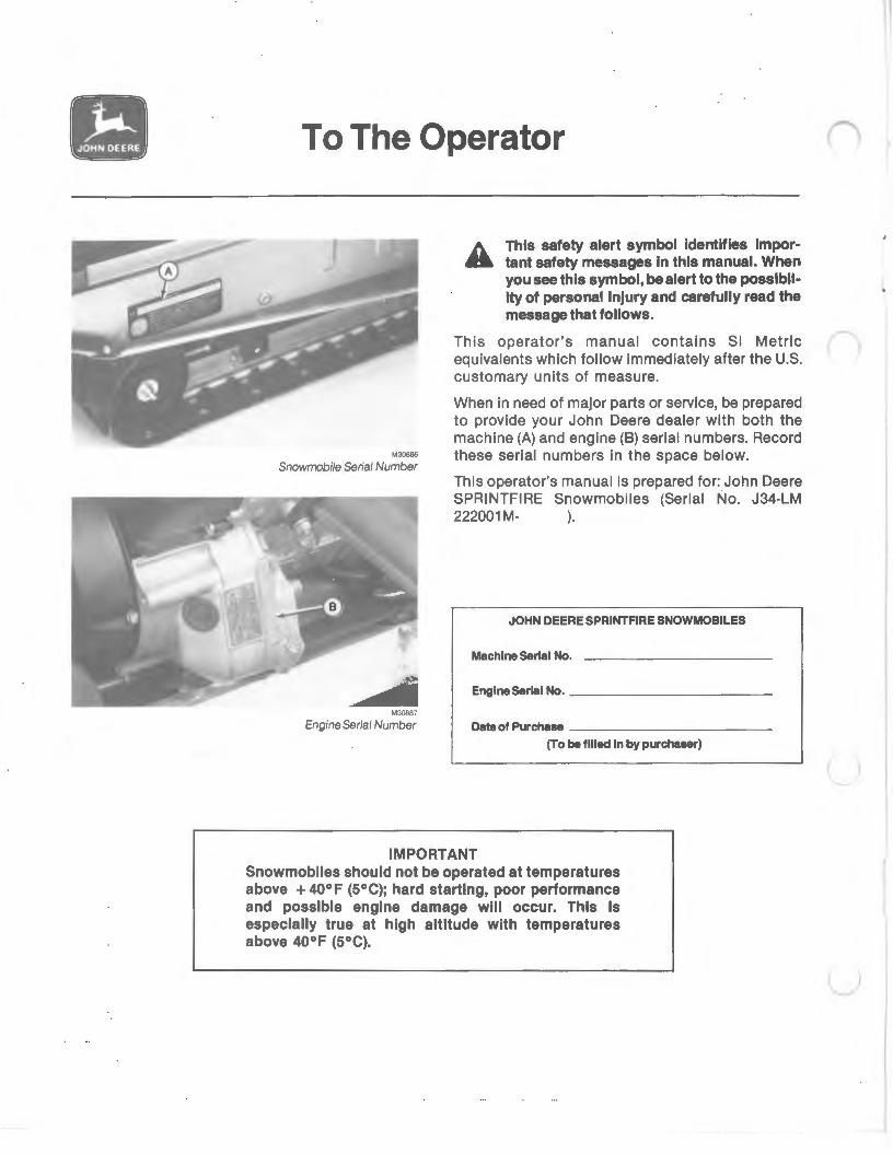
This safety alert symbol Identifies lmpor· tant safety messages In this manual. When you see this symbol, be alert to the posslbll· lty of personal Injury and carefully read the message that follows.
This operator's manual contains Sl Metric n equivalents which follow immediately after the U.S. customary units of measure.
M30886
Snowmobile Serial Number
M30887
Engine Serial Number
When in need of major parts or service, be prepared to provide your John Deere dealer with both the machine (A) and engine (B) serial numbers. Record these serial numbers in the space below.
This operator's manual is prepared for: John Deere SPRINTFIRE Snowmobiles (Serial No. J34-LM 222001 M- ).
JOHN DEERE SPRINTFIRE SNOWMOBILES
Machine Serial No.
Engine Serial No. __________ _
Date of Purchase ----------(To be filled In by purchaser)
IMPORTANT Snowmobiles should not be operated at temperatures above + 40°F (S°C); hard starting, poor performance and possible engine damage will occur. This is especially true at high altitude with temperatures above 40°F (S°C).
u
c
c
a Assembly
UNPACK COMPONENTS
1. Skis.
2. Windshield.
3. Operator's manual.
4. Bag of parts.
ASSEMBLE COMPONENTS
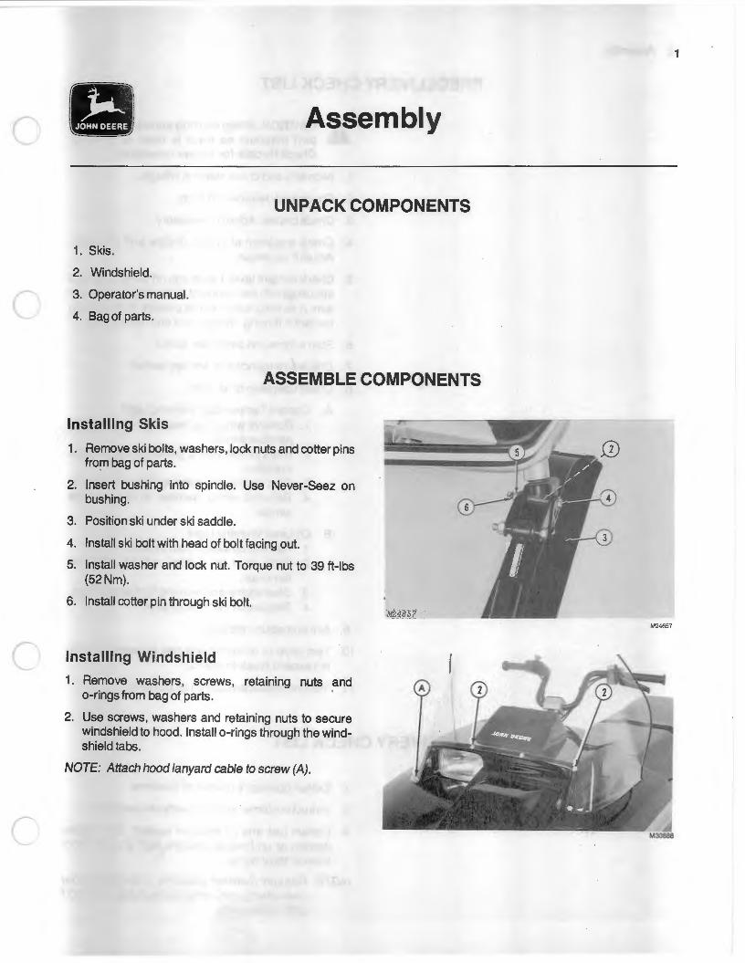
Installing Skis
1. Remove ski bolts, washers, lock nuts and cotter pins from bag of parts.
2. Insert bushing into spindle. Use Never-Seez on bushing.
3. Position ski under ski saddle.
4. Install ski bolt with head of bolt facing out.
5. Install washer and lock nut. Torque nut to 39 ft-lbs (52Nm).
6. Install cotter pin through ski bolt.
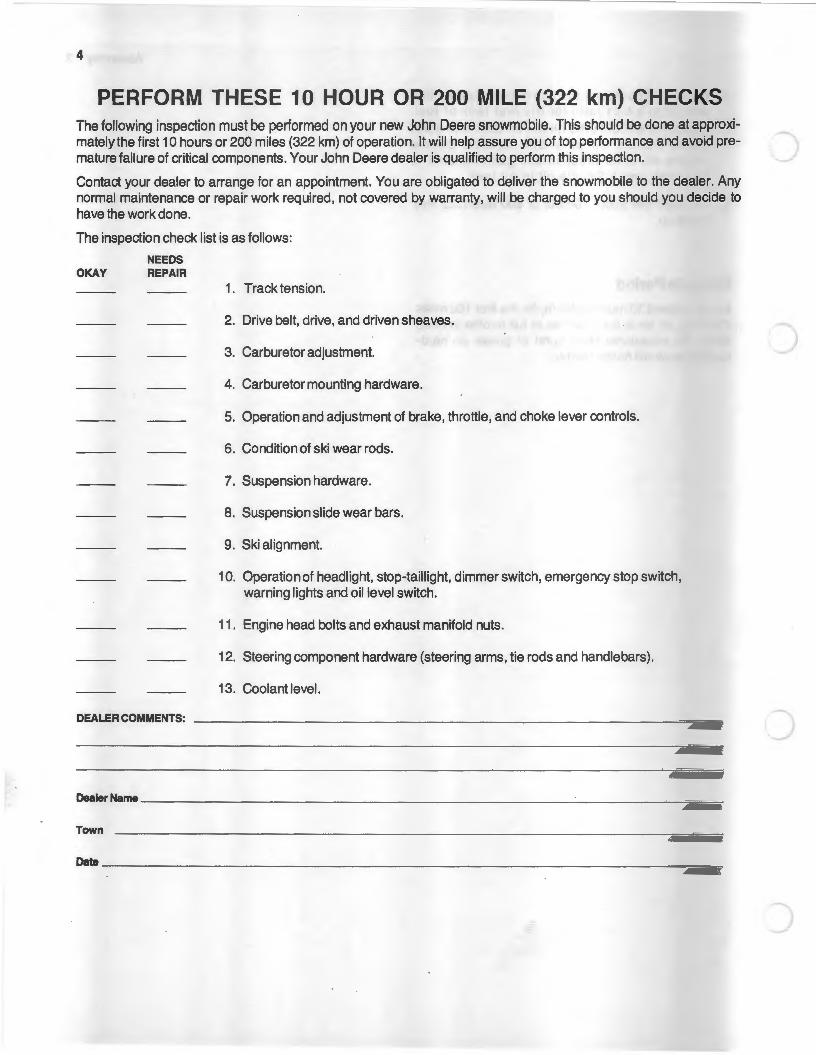
Installing Windshield
1. Remove washers, screws, retaining nuts and o-rings from bag of parts.
2. Use screws, washers and retaining nuts to secure windshield to hood. Install o-rings through the windshield tabs.
NOTE: Attach hood lanyard cable to screw (A).
1
M24657

2 Assembly
PREDELIVERY CHECK LIST
A CAUTION: When starting snowmobile, sup.. port machine so track is clear of ground.
Check throttle for proper operation.
1. Align skis and check steering linkage.
2. Check track tension and align.
3. Check brakes. Adjust if necessary.
4. Check operation of choke, throttle and oil pump. Adjust if necessary.
5. Check coolant level. Leave cap off surge tank and start engine to see if coolant is flowing through system. A swirling action will be present in tank when coolant is flowing. Stop engine and replace cap.
6. Start engine and check idle speed.
7. Check emergency stop and key switch.
8. Check operation of all lights.
A Coolant Temperature Warning Light 1 . Remove wiring harness from engine tem
perature sender. 2. Use a jumper wire to ground wiring harness
to engine. 3. Start engine and warning light should light. 4. Reinstall wiring harness to temperature
sender.
B. Oil Level Warning Light 1. Remove oil switch from oil tank. 2. Allow float to bottom out on electrical
terminals. 3. Start engine and warning light should light. 4. Replace oil switch in oil tank.
9. Aim and adjust headlight.
10. Test drive or dynamometer test snowmobile. (Do not exceed break-in speed}.
11 . Install accessories desired by customer.
DELIVERY CHECK LIST
1. Explain operator's manual to customer.
2. Instruct customer about snowmobile operation.
3. Explain fuel and oil injection system. Use regular (leaded or un-leaded) gasoline with an anti-knock index of 88 or higher.
NOTE: Regular (leaded) gasoline is preferred but unleaded gasoline is acceptable. DO NOT USE GASOHOL.

c
c
4. Explain to customer the use of pre-mix gasoline and oil in a 50:1 ratio for the first tank of fuel. Customer should also fill the oil tank with John Deere 2-Cycle Oil or a BIA certified 2-cycle engine oil. After break-in use gasoline only in fuel tank and a 2-cycle oil in oil tank.
5. Tell customer about 1 0-hour or 200 mile (322 km) checkup.
Break-In Period
Do not exceed 30 mph (48 km/h) for the first 100 miles (160 km), or force the machine at full throttle in deep snow. An occasional short burst of power on hardpacked snow will not be harmful.
Assembly 3
4
PERFORM THESE 10 HOUR OR 200 MILE (322 km) CHECKS The following inspection must be performed on your new John Deere snowmobile. This should be done at approximately the first 10 hours or 200 miles (322 km) of operation. It will help assure you of top performance and avoid prematurefailure of critical components. Your John Deere dealer is qualified to perform this inspection.
Contact your dealer to arrange for an appointment. You are obligated to deliver the snowmobile to the dealer. Any normal maintenance or repair work required, not covered by warranty, will be charged to you should you decide to have the work done.
The inspection check list is as follows:
NEEDS OKAY REPAIR
1. Track tension.
2. Drive belt, drive, and driven sheaves.
3. Carburetor adjustment.
4. Carburetor mounting hardware.
5. Operation and adjustment of brake, throttle, and choke lever controls.
6. Condition of ski wear rods.
7. Suspension hardware.
8. Suspension slide wear bars.
9. Ski alignment.
10. Operation of headlight, stop-taillight, dimmer switch, emergency stop switch, warning lights and oil level switch.
11. Engine head bolts and exhaust manifold nuts.
12. Steering component hardware (steering arms, tie rods and handlebars).
13. Coolant level.
DEALERCOMMENTS: --------------------------------------------------------------
DNier~me --------------------------------------------------------------------
Town
cam ______________________________________________________________________ __

1
c Contents
Page Page Safety ...................................................................... 2 Skis .................................................................... 22
Identification .......................................................... 5 Replacing Ski Wear Rods .......................... 22 Replacing Ski Wear Plates ........................ 23
Preparation ............................................................. 6 Aligning Skis ................................................ 23 Filling Fuel Tank ............................................... 6 Eliminating Loose Steering ....................... 23
c Filling Oil Tank .................................................. 6 Fuel Mix For Break-In Period .......................... 6 Fuel For Temperatures of
Lighting System .............................................. 24 Adjusting Headlight .... .. .............................. 24 Replacing Headlight ................................... 24
- 20°F (- 29°C) or Below ............................ 6 Replacing Stop-Taillight ............................. 25
Operation ................................................................ 7 Break-In Period .................................................. 7 Before Operating ............................................... 7
Replacing Oil Level Warning Light .......... 25 Replacing Coolant Temperature
Warning Light .......................................... 25
Starting Engine .................................................. 7 Tightening Hardware and Components ........... 26 Emergency Starting ................... ....................... 8 Stopping Engine ................................................ 8 Adjusting Glove Box Door Latch ...................... 26
Lights .................................................................. 9 Storage .................................................................. 27 Clearing Track .. ..... ............................................ 9 Towing ................................................................. 9 Trouble Shooting .......................... ....................... 28
Transporting ..................................................... 10 Specifications ...................................................... 30 Dressing For The Weather ............................. 10
Accessories .......................................................... 32 Service ............ .................................. .................... 11
Service Interval Chart ..................................... 11 Spark Plugs .... .................................................. 12 Carburetor and Oil Injection Pump .............. 13
Choke System .............................................. 13 Adjusting Choke Plunger ... ....... ................. 13 Adjusting Throttle Cable ............................ 14 Adjusting Oil Injection Pump .................... 15 Replacing Carburetor Main Jet ................. 15 Carburetor Recommendations .................. 16
In-Line Fuel Filter ............................................ 16 c In-Line Oil Filter .............................................. 17 Oil Injection Pump .................... ..... ................. 17 Air Intake Silencer .......................................... 17 Liquid Cooling System ................................... 18
Draining and Filling System ...................... 18 Drive System .............................. ...................... 19
Replacing Drive Belt ................................... 19 Adjusting Brake ........................................... 20
Slide Suspension ............................................. 20 Replacing Wear Bars .................................. 21 Adjusting Track Tension ............................ 21 Adjusting Rear Suspension Springs ........ 22 Adjusting Front Suspension Springs ....... 22
M23365
Safety
M23365
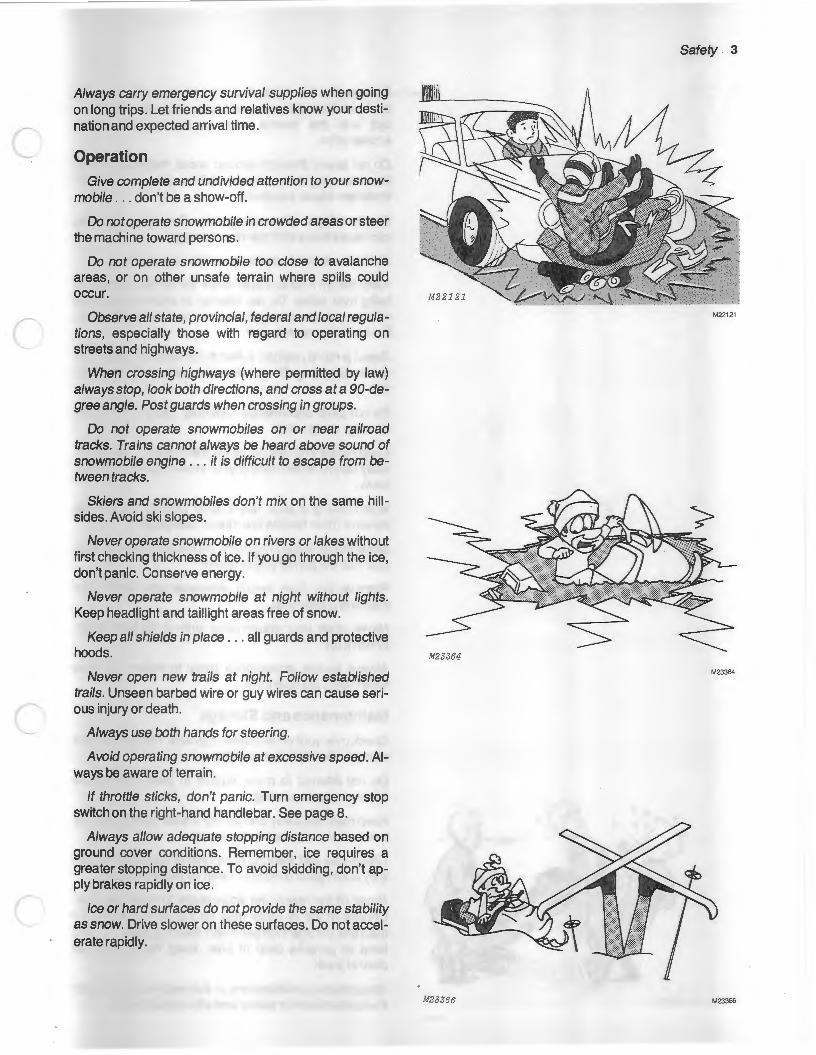
CAUTION: DO NOT carry a passenger. Improper use or maintenance by the operator can result in injury. Follow these safety suggestions.
Preparation
Before starting the engine, read your operator's manual from cover to cover. Knowledge can prevent accidents.
Always operate your throttle and brake controls several times before you start the engine. Stuck or frozen controls could cause serious injury or damage.
Know your controls. Learn how to stop in an emergency.
Know your state, provincial, federal and local laws pertaining to snowmobiling. Respect property of others. Don't spoil this fine winter sport by creating a bad image.
Never add fuel when smoking or while engine is running. Use a safe gasoline container. Always use fresh, clean fuel of the proper mixture. See page 6.
Wear clothing designed for snowmobiling . . . avoid frostbite. Never wear scarves, loose belts, or clothes that could catch on moving parts or tree limbs.
Always wear eye and headgear protection to guard against injury.
Prolonged exposure to loud noise can cause impairment or loss of hearing. Wear earplugs or any suitable hearing protective device that is comfortable when wearing a snowmobile helmet to protect against objectionable or uncomfortable loud noises. Always wear an approved helmet to guard against head injury.
Avoid sun blindness. Wear properly tinted goggles or face shield. Never wear yellow eye protection in the bright sun.
Do not allow anyone to operate snowmobile without proper instructions. Take proper precautions before allowingyoung operators to drive.
Always use the "buddy" system. Remember you can drive farther in 30 minutes than you can walk in a day.
Carry adequate tools and repair items for emergency field repairs.
Don't overload your snowmobile .. . use sleds to carry provisions.
c
c
c
Always carry emergency survival supplies when going on long trips. Let friends and relatives know your destination and expected arrival time.
Operation
Give complete and undivided attention to your snowmobile . . . don't be a show-off.
Do not operate snowmobile in crowded areas or steer the machine toward persons.
Do not operate snowmobile too close to avalanche areas, or on other unsafe terrain where spills could occur.
Observe all state, provincial, federal and local regulations, especially those with regard to operating on streets and highways.
When crossing highways (where permitted by law) always stop, look both directions, and cross at a 90-degree angle. Post guards when crossing in groups.
Do not operate snowmobiles on or near railroad tracks. Trains cannot always be heard above sound of snowmobile engine ... it is difficult to escape from between tracks.
Skiers and snowmobiles don't mix on the same hillsides. Avoid ski slopes.
Never operate snowmobile on rivers or lakes without first checking thickness of ice. If you go through the ice, don't panic. Conserve energy.
Never operate snowmobile at night without lights. Keep headlight and taillight areas free of snow.
Keep all shields in place ... all guards and protective hoods.
Never open new trails at night. Follow established trails. Unseen barbed wire or guy wires can cause serious injury or death.
Always use both hands for steering.
Avoid operating snowmobile at excessive speed. Always be aware of terrain.
If throttle sticks, don't panic. Turn emergency stop switch on the right-hand handlebar. See page 8.
Always allow adequate stopping distance based on ground cover conditions. Remember, ice requires a greater stopping distance. To avoid skidding, don't apply brakes rapidly on ice.
Ice or hard surfaces do not provide the same stability as snow. Drive slower on these surfaces. Do not accelerate rapidly.
Safety 3
M22121
M23364
M23366 M23366

4 Safety
M22 122
M22122
Be sure tool box lid is closed at all times. An open lid could cause interference with steering or possible contact with the throttle lever producing unexpected acceleration.
Do not speed through wooded areas. Hidden obstructions, hanging limbs, unseen ditches, and even wild animals can cause accidents.
Do not tailgate when riding trails. Rear end collisions can cause injury and machine damage.
Don't mix alcoholic beverages with snowmobiling.
Keep feet on footrests at all times. Do not permit them to hang over sides. Do not attempt to stabilize machine with feet when making turns or in near-spill situations. Broken limbs could result.
Select a riding position suited to the terrain upon which you're operating. Do not stand on seat, stunt, or showoff.
Do not jump snowmobile. Operator injury or machine damage could result.
Keep hands and feet out of the track area . .. be especially careful when freeing your snowmobile from deep snow.
When towing a sled, use a solid towbar. Do not use ropes or other flexible tow straps. See page 9.
Observe fuel supply regularly. Do not travel farther than your fuel will permit you to return.
Remove key from switch whenever you leave your machine unattended.
Never drive your snowmobile onto a tilt-bed trailer. Winch it on.
Always secure snowmobile firmly to trailer. Be sure trailer lights are operative.
Maintenance and Storage
Check over your snowmobile regularly. This will prevent many problems from occurring.
Do not attempt to make repairs to your snowmobile While engine is running.
Keep matches away and do not smoke while filling the fuel tank. Avoid possible explosions.
Check skis and steering components frequently to see they are in good condition. Keep all hardware tight.
Never lift the rear of the snowmobile to clear the track. Chunks of ice or rocks may be thrown rearward. Tilt machine on one footrest when clearing track ... and keep all persons clear of area. Keep hands and feet clear of track.
Unauthorized modifications to the machine may impa'ir the function and/or safety and affect machine life.
c
(
c
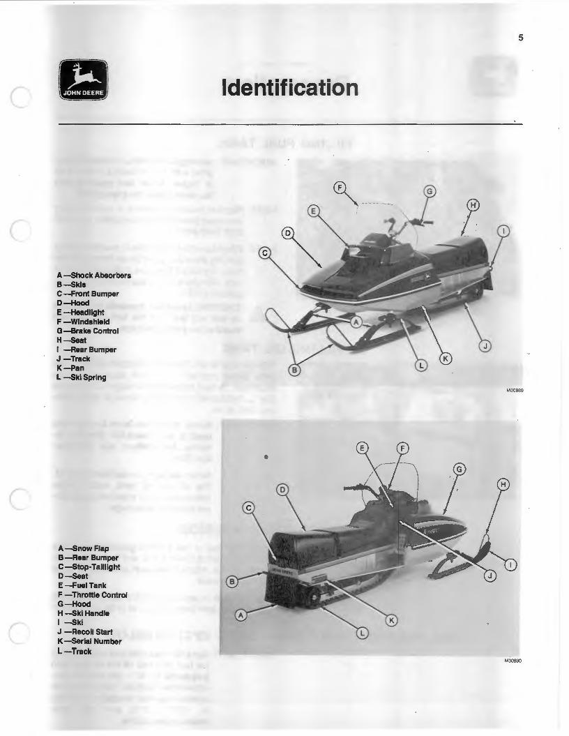
A -shock Absorbers B-skls C -Front Bumper 0-Hooc:l E-Headllght F -Windshield G-Brake Control H--seat I -Rear Bumper J -Track K-Pan L -ski Spring
A-snow Flap B -Rear Bumper C -stop-Taillight o--seat E-FueiTank F -Throttle Control G-Hood H -$kl Handle I -$kl J -Recoil Start K -serial Number L-Track
5
Identification
~---
M30889
M30890

Preparation
FILLING FUEL TANK IMPORTANT: Use regular leaded or un-leaded gas
oline with an anti-knock index of 88 or higher. Never use gasoline that has been stored for a long time.
NOTE: Regular (leaded) gasoline is preferred but unleaded gasoline is acceptable. DO NOT USE GASOHOL.
NOTE: When running snowmobile in powder snow or blowing snow add gasoline de-icer to the fuel tank. Use ONLY 8 ounces (0.24 L) per tank of fuel. Fuel tank holds approximately 5 U.S. gallons (18.9 L).
CAUTION: Excessive amounts of gasoline de-icer will lean out the fuel mixture and could cause engine damage.
FILLING OIL TANK NEVER ALLOW OIL TANK TO BECOME EMPTY. Use John Deere 2-cycle oil or a BIA approved 2-cycle engine oil. Oil tank holds approximately 5.0 U.S. pints (2.4 L). Refill tank immediately when oil level warning light is on.
IMPORT ANT: If other than John Deere 2-cycle oil is used, it must meet BIA (Boating Industry Association) test qualificationTCW.
Never use dirty or contaminated oil. The oil and oil tank must remain clean to avoid oil injection pump failure and engine damage.
FUEL MIX FOR BREAK-IN PERIOD For the first tank of fuel, pre-mix gasoline and oil in a 50:1 ratio (1 pint of oil with 6 U.S. or 5 Imperial gallons) and fill fuel tank. Fill the oil tank with John Deere 2-cycle oil or its equivalent.
After the break-in period, use ONLY GASOLINE in the fuel tank and John Deere 2-cycle oil or its equivalent in the oil tank.
FUEL FOR TEMPERATURES OF -200F ( -29°C) OR BELOW IMPORTANT: Use a 50:1 gasoline and oil pre-mix In
the fuel tank and fill the oil tank with 2-cycle oil. DO NOT use straight gasoline In the fuel tank. The oil injection system may not function efficiently at - 20"F (- 29°C) and this could cause engine failure.
(
r
Operation
BREAK-IN PERIOD Do not exceed 30 mph (48 km/h) for the first 100 miles (160 km) or force the machine at full throttle in deep snow. An occasional short burst of power on hardpacked snow will not be harmful.
BEFORE OPERATING 1 . Clean windshield with a damp cloth. Do not use gas
oline, solvents, or abrasive cleansers. 2. Check skis, wear rods, and all steering components.
Check steering for a full right and left-hand turn. 3. Check track for proper tension. 4. Check fuel and oil levels. Oil level must be checked
each time that fuel is added. 5. Check throttle and brake controls for free operation
and proper adjustment. 6. Start engine and test operation of emergency stop
switch, key switch, headlight dimmer switch, headlight, and stop-tailight.
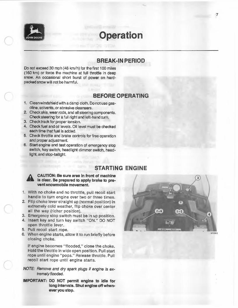
STARTING ENGINE CAUTION: Be sure area In front of machine Is clear. Be prepared to apply brake to prevent snowmobile movement.
1. With no choke and no throttle, pull recoil start handle to turn engine over two or three times.
2. Flip choke lever straight up (normal position) in extremely cold weather, flip choke over center all the way (richer position).
3. Emergency stop switch must be in up position. 4. Insert key and turn key switch "ON." DO NOT
open throttle lever. 5. Pull recoil start rope. 6. When engine starts, allow it to run briefly before
closing choke.
If engine becomes "flooded," close the choke. Hold the throttle in wide open position. Pull start rope until engine "pops." Release throttle. Pull recoil start rope until engine starts.
NOTE: Remove and dry spark plugs if engine is extremely flooded.
IMPORTANT: DO NOT permit engine to Idle for long Intervals. Shut engine off whenever you stop.
7
M30893
8 Operation
Warm Starting
With emergency stop switch in center position and key swtich "ON," pull recoil start rope.
NOTE: DO NOT use choke and open throttle slightly.
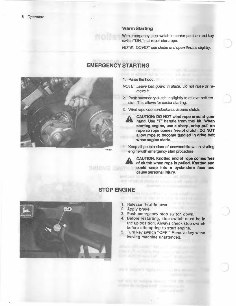
EMERGENCY STARTING
M30894
1 . Raise the hood.
NOTE: Leave belt guard in place. Do not raise or remove it.
2. Push secondary clutch in slightly to relieve belt tension. This allows for easier starting.
3. Wind rope counterclockwise around clutch.
A CAUTION: DO NOT wind rope around your .. hand. Use "T" handle from tool kit. When
starting engine, use a sharp, crisp pull on rope so rope comes free of clutch. DO NOT allow rope to become tangled in drive belt when engine starts.
4. Keep all people clear of snowmobile when starting engine with emergency start procedure.
CAUTION: Knotted end of rope comes free of clutch when rope is pulled. Knotted end could snap into a bystanders face and cause personal injury.
STOP ENGINE
1. Release throttle lever. 2. Apply brake. 3. Push emergency stop switch down. 4. Before restarting, stop switch must be in
the up position. Always check stop switch before attempting to start engine.
5. Turn key switch "OFF." Remove key when leaving machine unattended.
c
(
(
c
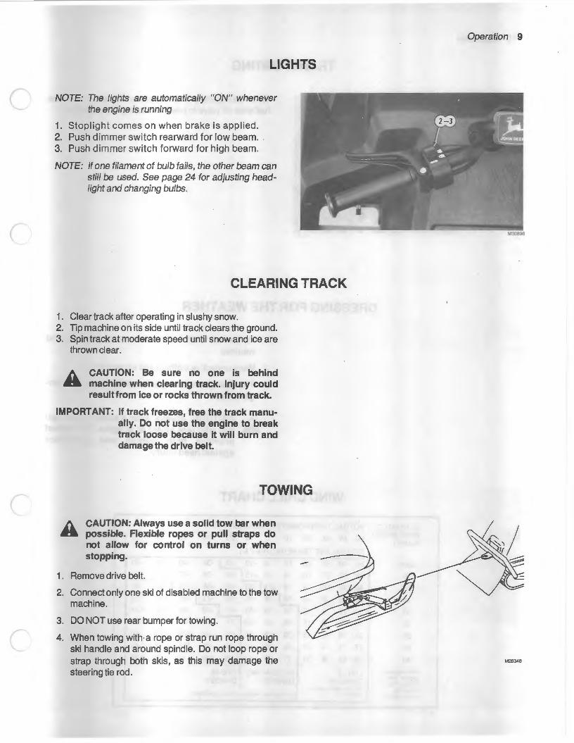
LIGHTS
NOTE: The lights are automatically "ON" whenever the engine is running
1. Stoplight comes on when brake is applied. 2. Push dimmer switch rearward for low beam. 3. Push dimmer switch forward for high beam.
NOTE: If one filament of bulb fails, the other beam can still be used. See page 24 for adjusting headlight and changing bulbs.
CLEARING TRACK
1 . Clear track after operating in slushy snow. 2. Tip machine on its side until track clears the ground. 3. Spin track at moderate speed until snow and ice are
thrown clear.
A CAUTION: Be sure no one is behind .a machine when clearing track. Injury could
result from ice or rocks thrown from track.
IMPORTANT: If track freezes, free the track manually. Do not use the engine to break track loose because it will burn and damage the drive belt.
TOWING
CAUTION: Always use a solid tow bar when possible. Flexible ropes or pull straps do not allow for control on turns or when stopping.
1 . Remove drive belt.
2. Connect only one ski of disabled machine to the tow machine.
3. DO NOT use rear bumper for towing.
4. When towing with· a rope or strap run rope through ski handle and around spindle. Do not loop rope or strap through both skis, as this may damage the steering tie rod.
Operation 9
M28348

1 0 Operation
TRANSPORTING
When transporting snowmobile on a trailer, close the fuel shut-off valve to prevent flooding of the engine.
DRESSING FOR THE WEATHER
ESTIMATED WIND SPEED IN MPH
calm
5
10
15
20
25
30
35
40
(Wind speeds g realer than 40 mph have littleaddi-tiona I effect.)
M10123
1. To be safe from frostbite, dress for the wind and weather.
2. Wear protective clothing and accessories.
3. The chart provides a guide and illustrates the danger zones.
CAUTION: Always wear a snowmobile helmet with face shield or goggles. The helmet provides both warmth and protection against head Injury.
WIND CHILL CHART
ACTUAL THERMOMETER READING (°F.)
50 40 30 20 10 0 -10 -20 -30 -40 -50 -60
EQUIVALENT TEMPERATURE (°F)
50 40 30 20~.-30 -40 -50 -60
48 37 27 16 6 -5 -15 -26 -36 -47 -57 -68
40 28 16 4 -9 -21 -33 -46 -58 -70 -83 -95
36 22 9 -5 -18 -36 -45 -58 -72 -85 -99 -112
32 18 4 -10 -25 -39 -53 -67 -82 -96 -110 -124
30 16 0 -15 -29 -44 -59 -74 -88 -104 -118 -133
28 13 -2 -18 -33 -48 -63 -79 -94 -109 -125 -140
27 11 -4 -20 -35 -49 -67 -82 -98 -113 -129 -145
26 10 -6 -21 -37 -53 -69 -85 -100 . -116 -132 -148
LITTLE INCREASING GREAT DANGER DANGER DANGER (for properly c lothed person) Danger from freezing of exposed flesh
M\01 23
)

11
c Service
SERVICE INTERVAL CHART
Every Every As 150 300
Item Needed Dally Miles Miles Annually Page
Clean windshield X 7
Check coolant level. X 18
Check condition of skis and steering. X 22, 23
Check track condition and tension X 21
Check throttle control operation. X 13, 14
Check operation of brakes. X 20
Check emergency stop and key switches. X 8
Check lighting system. X 9
See your John Check coolant temperature warning light. X Deere Dealer
See your John Check oil level warning light. X Deere Dealer
See your John Check oil injection pump drive belt. X Deere Dealer
Check oil injection pump and cable. X 15
Check in-line fuel filter. X 16
Check in-line oil filter. X X 17
c Check drive belt condition. X 19
Check carburetor adjustments. X X X 14, 15
Check choke adjustments. X X X 13
Check ski alignment. X 23
Check headlight adjustment. X 24
Check ski wear rods and wear plate. X X 22, 23
Check slide suspension wear bars. X X 21
Oil throttle cable. X 15 c Check all components for condition and tightness. X 26
Service drive and driven sheaves. X 19
Store snowmobile properly. X 27

12 Service
SPARK PLUGS
NOTE: Spark plugs are Champion QN-2 (John Deere Part No. AM55044).
Removing Spark Plugs
A CAUTION: High-energy ignition systems .. can produce injurious electrical shock.
Stop engine and remove key before working on ignition.
1. Stop engine.
2. Pull connectors from plugs.
)
IMPORT ANT: Do nut pull on wire to remove con- ) nectors. Pull on connectors only.
M30898
3. Removeplugs.
Checking for Spark A CAUTION: Do not hold the plug or plug wire .. in your hand when checking for spark. High
energy ignition systems can produce injurious electrical shock. DO NOT remove plugs from engine for this test. If crankcase is full of fuel and engine is turned over, gasoline may spew out spark plug hole, causing a fire hazard.
1. Reconnect spark plug wire to a spare plug.
2. Lay plug on the engine
3. Pull the recoil start rope and check for spark.
New plugs are gapped at 0.025 inch (0.635 mm). The gap will widen in proportion to the hours and miles of use. When plug gap reaches 0.045 inch (1.143 mm) or if plug malfuntions, replace it.
IMPORTANT: Do not regap the plug, always replaceltl
Plug Appearance Possible cause
Tan or Cocoa Brown Properfuel mixture, good combustion.
Black or Sooty Fuel mixture too rich, poor combustion.
White or Light Tan Fuel mixture too lean, hot combustion.
NOTE: Replace plug if appearance is abnormal, engine starts hard or malfunctions.
Installing Spark Plugs 1. Clean plug seating surface on cylinder head. 2. Install plugs and torque to 20 ft-lbs (27N·m). 3. Install spark plug wires.
NOTE: See page 30 for spark plug recommendation.
)
(
CARBURETOR AND OIL INJECTION PUMP
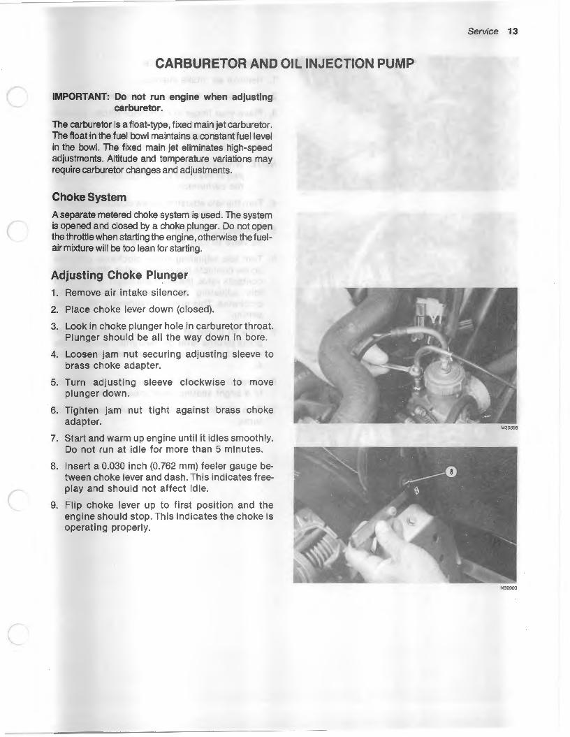
IMPORTANT: Do not run engine when adjusting carburetor.
The carburetor is a float-type, fixed main jet carburetor. The float in the fuel bowl maintains a constant fuel level in the bowl. The fixed main jet eliminates high-speed adjustments. Altitude and temperature variations may require carburetor changes and adjustments.
Choke System
A separate metered choke system is used. The system is opened and closed by a choke plunger. Do not open the throttle when starting the engine, otherwise the fuelair mixture will be too lean for starting.
Adjusting Choke Plunger
1. Remove ai r intake silencer.
2. Place choke lever down (closed).
3. Look in choke plunger hole in carburetor throat. Plunger should be all the way down in bore.
4. Loosen jam nut securing adjusting sleeve to brass choke adapter.
5. Turn adjusting sleeve clockwise to move plunger down.
6. Tighten jam nut tight against brass choke adapter.
7. Start and warm up engine until it idles smoothly. Do not run at idle for more than 5 minutes.
8. Insert a 0.030 inch (0.762 mm) feeler gauge between choke lever and dash. This indicates f reeplay and should not affect idle.
9. Flip choke lever up to first position and the engine should stop. This indicates the choke is operating properly.
Service 13
M30899

14 Service
Adjusting Throttle Cable
1. Remove air intake silencer.
2. Tape throttle lever tight against handgrip.
3. Place your finger in carburetor throat. Loosen jam nut and turn adjusting sleeve clockwise (in) until the backside of throttle valve is flush with the inside of bore. Tighten jam nut.
NOTE: When throttle valve is adjusted correctly, no part of the valve will restrict air flow through the carburetor.
4. Turn the idle adjusting screw counterclockwise until the screw tip is flush with inside of bore.
)
5. Remove tape from throttle lever and allow throt- ) tie valve to fully seat in bore.
6. Turn idle adjusting screw clockwise until the screw contacts the throttle valve. When screw contacts valve, the valve will begin to rise. Turn idle adjusting screw two additional turns clockwise. This gives a preliminary idle speed setting.
7. Look in throat of carburetor and slowly compress throttle lever on handgrip. Throttle valve should begin to rise, if not repeat steps 2, 3 and 4.
8. Carefully turn pilot air screw clockwise (in) until a slight seating resistance is felt.
9. Turn pilot air screw counterclockwise (out) 1-1/2 turns.

c
(
Adjusting Oil Injection Pump
IMPORTANT: Adjust the oil injection pump lever to move at exactly the same time that the carburetor throttle valve starts to move. Never run the engine without oil supply to the oil pump, even if premix is used. If oil pump runs dry, pump failure will result.
1. Loosen jam nuts (A) of oil injection pump cable. Back sleeve (B) out to tighten cable or in to loosen cable.
2. Adjust cable so straight edge of oil pump control arm aligns with vertical mark on oil pump body. Tighten jam nut.
3. Press throttle lever on handgrip and observe throttle valve and oil injection pump control lever. Both should start to move at exactly the same time.
IMPORTANT: Lubricate throttle cable once each season with LPS or WD-40. Hold the throttle lever against the handgrip and allow lubricant to run down cable. DO NOT use engine oil or silicone spray. These lubricants may destroy the plastic components of the throttle cable or cause control cable to become sticky in cold temperatures.
Replacing Carburetor Main Jet
1. Remove throttle valve assembly from top of carburetor.
2. Loosen clamp securing carburetor to intake manifold.
3. Loosen clamp securing intake silencer boot to carburetor.
4. Turn carburetor 90 degrees.
A CAUTION: Fuel in carburetor float bowl .. drains out when hex. plug is removed. Place
sufficient material under carburetor to soak up spilled fuel, when plug is removed. Avoid fires due to smoking or careless maintenance practices.
5. Use a 17 mm wrench to remove hex. plug from bottom of carburetor.
6. Replace main jet.
7. Reverse procedure to install carburetor.
Service 15

16 Service
Temperature
Below 0°F ( -18°C}
Above 0°F ( -18°C}
All Temperatures
CARBURETOR RECOMMENDATIONS
Component
Main Jet
Main Jet
Jet Needle
Needle Jet
Throttle Valve
Pilot Jet
Air Screw
Idle Speed
Carburetor and clutch changes, adjustments or modifications may be necessary for operation at altitudes above 4000 feet (1219 m). See your John Deere dealer for these changes.
Sea Level to 4000 to 8000 8000 Feet 4000 Feet Feet and Above (1 219 m) (1 219 to 2438 m) (2438 m)
175 155 135
165 145 125
6DH4-2 6DH4-2 6DH4-2
(1 59) P-4 (159) P-4 (159) P-4
2.5 2.5 2.5
30 35 30
1-3/4 Turns 1-1/2 Turns 1-1/2 Turns Open Open Open
2000-2100 rpm 2400-2500 rpm 2400-2500 rpm
IN-LINE FUEL FILTER
Change the filter annually.

c
c
IN-LINE OIL FILTER
Replace oil filter annually or immediately if oil level in tank does not drop.
OIL INJECTION PUMP
Check oil injection pump (A) oil flow annually. See your John Deere dealer for this service.
AIR INTAKE SILENCER
The first indication of trash in the silencer will be loss of power and performance. The engine will run "rich" because adequate air will not be mixing with the fuel.
1. Remove silencer screen. 2. Shake or blow out the screen to remove any trash. 3. Install silencer screen.
IMPORTANT: DO NOT run engine with air intake silencer removed.
Service 17

18 Service
LIQUID COOLING SYSTEM
M29122
The liquid cooling system is pressurized. A heat exchanger is located in the tunnel. Snow against the exchanger cools the system.
A warning light is incorporated in the system and will turn on if the temperature reaches 205°F (96°C). The rad iator cap releases pressure at 12 to 13 psi (82.7 to 89.6 kPa) allowing the cooling system to overflow.
IMPORTANT: Running on hard-packed snow or ice or pulling loads may cause overheatIng. If coolant temperature warning light goes on, reduce load and immediately run in loose snow or shut off engine.
During the initial break-in period, operate the snowmobile for five minutes. Allow the engine to cool slightly before opening the surge tank cap to check coolant level. Coolant level should be one inch below the filler neck. Capacity of the system is approximately 5 quarts (4.7 L).
If coolant is lower than two inches below filler neck, coolant must be added. Use a 50-50 solution of ethylene glycol anti-freeze and water. DO NOT use any anti-freeze containing a radiator stop-leak. NEVER add radiator stop-leak to the cooling system.
IMPORTANT: DO NOT exceed the recommended 50-50 solution. Never add anti-freeze to fill the system until after checking the solution with a hydrometer. A 50-50 solution should give approximately a -40"F ( -40"C) reading. Check solution when engine is completely warmed up.
Draining and Filling System
Draining System (2 Year Intervals Only)
1. Remove drain screw and pressure cap.
2. Remove lower hose from heat exchanger.
3. Raise rear of snowmobile slightly to drain system. Replace drain screw and lower hose.
4. Wash engine and compartment with clean water.
c
(
c
Filling System
1. Connect lower hose to heat exchanger and replace drain screw.
2. Position snowmobile on a level surface.
3. Fill the system with a 50-50 solution of ethylene glycol anti-freeze and water to bottom of filler neck on surge tank. System capacity is approximately 5 U.S. quarts (4.7 L).
4. Check all hose connections for leaks.
5. Block up track so engine can be run safely. Start engine and check for coolant flowing in system. There will be a swirling action in the top of the surge tank when coolant is flowing. Install pressure cap.
DRIVE SYSTEM
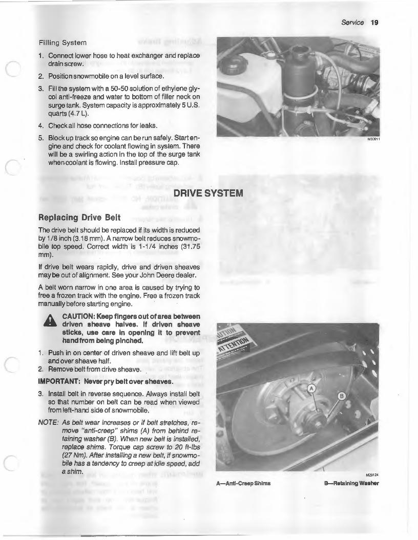
Replacing Drive Belt
The drive belt should be replaced if its width is reduced by 1/8 inch (3.18 mm). A narrow belt reduces snowmobile top speed. Correct width is 1-1/4 inches (31.75 mm).
If drive belt wears rapidly, drive and driven sheaves may be out of alignment. See your John Deere dealer.
A belt worn narrow in one area is caused by trying to free a frozen track with the engine. Free a frozen track manually before starting engine.
A CAUTION: Keep fingers out of area between .a driven sheave halves. If driven sheave
sticks, use care In opening It to prevent hand from being pinched.
1. Push in on center of driven sheave and lift belt up and over sheave half.
2. Remove belt from drive sheave.
IMPORTANT: Never pry belt over sheaves.
3. Install belt in reverse sequence. Always install belt so that number on belt can be read when viewed from left-hand side of snowmobile.
NOTE: As belt wear increases or if belt stretches, remove "anti-creep" shims (A) from behind retaining washer (B). When new belt is installed, replace shims. Torque cap screw to 20 ft-lbs (27 Nm). After installing a new belt, if snowmobile has a tendency to creep at idle speed, add a shim.
A-Anti·Creep Shims
Service 19
M30911
8-Retalnlng Washer

20 Service
A--Jam Nut
1-1-1/2" (25-38 mm)
M30912
B-Adjustlng Screw
Adjusting Brake
1. Apply the brake control lever and measure the distance from the lever to the hand grip. It should be 1 to 1-1 /2 inches (25 to 38 mm).
2. Adjust brake by loosening jam nut (A) and tightening adjusting screw (B). Tighten jam nut.
A CAUTION: NO NOT adjust jam nuts on .. brakecable.
3. Check brake tension.
4. Readjust if necessary.
NOTE: Be certain dowel on end of brake cable is seated property in recess of brake control/ever.
5. After brake adjustment, check operation of stoplight switch. If stoplight does not work, check for a defective switch.
SLIDE SUSPENSION The slide suspension system requires lubrication between the plastic wear bar and the track grouser bar. The absence of lubrication (snow or water) causes the plastic wear bar to wear rapidly and in severe cases, literally melt away.
Operation of the snowmobile under the following conditions should be avoided. 1. Dirt 2. Rocks 3. Sand 4. Grass 5. Bare Pavement 6. Snow permeated with dirt and sand. 7. Glare ice surfaces
IMPORTANT: When running on ice or hard pack snow at high-speed, the wear bars will heat up. Either reduce speed, or frequently stop and apply Ice or snow to the track to lubricate the wear bars.
(
c
Replacing Wear Bars
When running in marginal snow conditions, check wear bars daily.
1. Tip snowmobile on its side. 2. Check wear bars in several places for cracks, thin
areas and sand or gravel imbedded in the bar.
NOTE: Sand or gravel imbedded in the wear bars acts as an abrasive and will destroy the steel grouser bars in the track.
3. If any of these conditions exist, see your John Deere dealer for wear bar replacement.
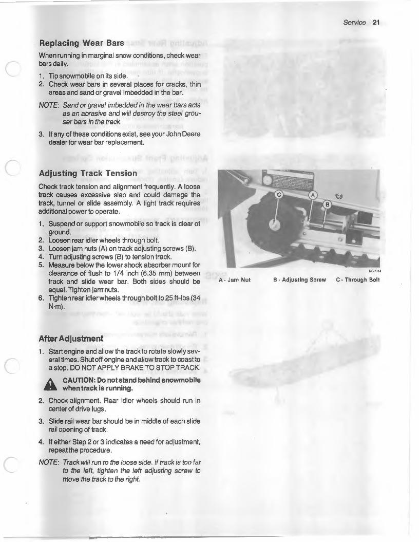
Adjusting Track Tension
Check track tension and alignment frequently. A loose track causes excessive slap and could damage the track, tunnel or slide assembly. A tight track requires additional power to operate.
1. Suspend or support snowmobile so track is clear of ground.
2. Loosen rear idler wheels through bolt. 3. Loosen jam nuts (A) on track adjusting screws (B). 4. Turn adjusting screws (B) to tension track. 5. Measure below the lower shock absorber mount for
clearance of flush to 1/4 inch (6.35 mm) between track and slide wear bar. Both sides should be equal. Tighten jam nuts.
6. Tighten rear idler wheels through bolt to 25 ft-lbs (34 N·m).
After Adjustment
1. Start engine and allow the track to rotate slowly several times. Shut off engine and allow track to coast to a stop. DO NOT APPLY BRAKE TO STOP TRACK.
A CAUTION: Do not stand behind snowmobile .. when track Is running.
2. Check alignment. Rear idler wheels should run in center of drive lugs.
3. Slide rail wear bar should be in middle of each slide rail opening of track.
4. If either Step 2 or 3 indicates a need for adjustment, repeatthe procedure.
NOTE: Track will run to the loose side. If track is too far to the left, tighten the left adjusting screw to move the track to the right.
Service 21
M30914
A· Jam Nut B · Adjusting Screw C · Through Bolt

22 Service
M30915
Adjusting Rear Suspension Springs
The rear suspension springs (A) are in the middle position when assembled at the factory. Ride the snowmobile. If ride needs to be stiffer move the springs to the upper position. If the ride needs to be softer move the springs to the lower position.
NOTE: To change spring position, remove long arm of spring from front retainer and pull out and down. Move short arm of spring to desired position and replace long arm on retainer.
Adjusting Front Suspension Springs
1. Turn adjusting nut (A) counterclockwise to reduce tension, clockwise to increase tension.
2. In deep snow (for more lift) increase tension. In light snow (for more steering control) reduce tension.
IMPORTANT: Never turn adjusting nut (A) all the way out. Screw (B) must protrude at least 112 inch (12.7 mm) through ad· justing nut (A).
SKIS
M30921
Replacing Ski Wear Rods
. Wear rods should be replaced when they are worn to one-half their original size.
1. Remove lock nuts securing wear rod to ski.
2. Pry rod down to free studs from holes.
3. Slide rod forward to remove rod from rear hole.
4. Install new rod in opposite sequence.
)
)

c
c
c
Replacing Ski Wear Plates
Replace wear plates when excessively worn.
1. Raise front of snowmobi I e.
2. Remove cotter pin (A), nut (B), and bolt (C).
3. Lift spring and remove wear plate (D).
4. Install new wear plate.
5. Lower spring and install bolt, nut, and cotter pin.
Aligning Skis
When properly aligned, skis are parallel and handlebars are positioned straight ahead.
1. Loosen jam nuts (D). Gold-colored tie rod ends (C) have left-hand threads. Loosen opposite normal rotation.
2. Turn tie rods to align skis. Measure from straight edges of skis; not tapered ends.
IMPORT ANT: When adjusting tie rods (B), length from center hole-to-center hole should not exceed 14-1/2 Inches (36.8cm).
3. Tighten jam nuts (D). Hold tie rod (B) with vice grips when tightening jam nuts. This prevents stripping the threads in the ball joint. ·
IMPORTANT: After jam nuts are tight, be sure tie rod ends (A) still swivel freely.
Eliminating Loose Steering
A CAUTION: Check steering components and A hardware frequently for condition and
tightness.
The two major causes of loose steering are:
1. Excessivelyworntie rod ends (A).
2. Excessively worn spindle bushings.
3. Replace or tighten parts as required.
A-neRodEnd B-neRod C -Gold-Colored ne Rod End D-JamNuta
Service 23
M30918

24 Service
LIGHTING SYSTEM
25' ~-------------------(7.6 m)----------------------~
~~==-======-======~
M29130
Adjusting Headlight
24 - 3/4" (628 11111)
M29136
1 . Position snowmobile on a flat surface with the headlight 25 feet (7.6 meters) from a vertical surface.
2. Have operator on seat and headlight on HIGH beam. Light beam centerline should be straight ahead and 24-3/4 inches (628 mm) above ground level.
3. Loosen or tighten the two left-hand adjusting screws to raise or lower the light beam.
4. Loosen or tighten the right-hand adjusting screw to move the light beam right or left.
Replacing Headlight
1. Disconnect wiring harness from light bulb.
2. Push and turn bulb counterclockwise to remove bulb.
3. Install new bulb in opposite sequence.
IMPORTANT: Be sure bulb locking tabs match slots.
4. Connect wiring harness to light bulb.
(
(
c
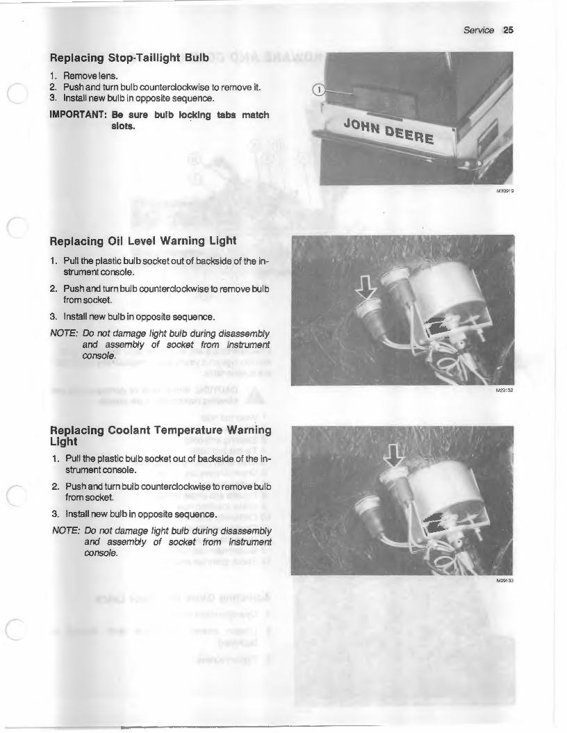
Replacing Stop-Taillight Bulb
1. Remove lens. 2. Push and turn bulb counterclockwise to remove it. 3. Install new bulb in opposite sequence.
IMPORTANT: Be sure bulb lo~klng tabs match slots.
Replacing Oil Level Warning Light
1. Pull the plastic bulb socket out of backside of the instrument console.
2. Push and turn bulb counterclockwise to remove bulb from socket.
3. Install new bulb in opposite sequence.
NOTE: Do not damage light bulb during disassembly and assembly of socket from instrument console.
Replacing Coolant Temperature Warning Light 1. Pull the plastic bulb socket out of backside of the in
strument console.
2. Push and turn bulb counterclockwise to remove bulb from socket.
3. Install new bulb in opposite sequence.
NOTE: Do not damage light bulb during disassembly and assembly of socket from instrument console.
Service 25
M30919
M29132
M29133

26 Service
TIGHTENING HARDWARE AND COMPONENTS
M29135
M30920
Check hardware and components for tightness, wear and damage on a yearly basis. Replace any parts that are questionable.
A CAUTION: Worn, bent or damaged ski and .a steering components are unsafe.
1 . Wear rod nuts. 2. Ski bolts. 3. Steering arm bolts. 4. Tie rod end bolts. 5. Drive shaft bearing cap screws. 6. Driven sheave cap screw. 7. Muffler spring. 8. Throttle and choke cables. 9.1ntake manifold nuts.
1 0. Carburetor attachment. 11. Engine mounting bolts. 12. Drive sheave cap screw. 13. Suspension cap screws. 14. Shock absorber screws.
Adjusting Glove Box Door Latch 1 . Open glove box door.
2. Loosen screws and move latch forward or backward.
3. Tighten screws.

c
Storage
PLACE SNOWMOBILE IN STORAGE
1. Thoroughly clean snowmobile. 2. Polish hood, pan and tunnel with automotive-type
wax. Use upholstery cleaner on seat. Touch up all bare metal parts with paint.
3. Check cap screws and components for tightness. Order any new parts required
IMPORTANT: Use John Deere Gasoline Storage Stabilizer (TY6295) or equivalent In the fuel tank. Gasoline storage stabl· llzer should always be used when storing the snowmobile to prevent carburetor varnishing and partial plugging of carburetor jets. Either of these conditions could cause the engine to run lean and result In piston seizure and engine failure.
4. Replace in-line fuel filter. 5. Remove spark plugs and add one teaspoon of
2-cycle oil in each cylinder. Pull recoil start rope six or seven times to lubricate cylinder walls. Replace plugs.
6. Remove drive belt and coat drive and driven sheaves with light grease.
7. Support snowmobile so track is clear of ground. Loosen track adjusting screws.
8. Place cover on snowmobile and store inside.
REMOVE SNOWMOBILE FROM STORAGE
1. Wipe grease from drive and driven sheaves. Install drive belt.
2. Fill fuel tank and oil tank. 3. Check throttle and brake controls for proper adjust-
ment and operation. 4. Adjusttrack tension. 5. Review operating and safety suggestions. 6. Start engine and test operation of all switches and
lights. 7. Ride snowmobile at slow speed until you are sure it
is operating properly.
27

Trouble Shooting
ENGINE Engine Starts Hard or Will Not Start Fuel tank empty. Emergency stop switch in "STOP" position. Plugged in-line fuel filter. Fuel pump malfunctioning. Faulty ignition system. Ignition timing incorrect. Idle set too high.
Engine Lacks Power or Acceleration Running on one cylinder. Throttle cable improperly adjusted. lmproperfuel mixture. Carburetor out of adjustment. Restricted in-line fuel filter. Ignition timing incorrect. Center distance between drive and driven sheaves too
short for belt.
Engine Backfires and Runs Unevenly Ignition timing incorrect. Too Lean Fuel Mixture
Engine Overheats Carburetor too "lean". Intake manifold or carburetor leaking. lnsuffieient snow for heat exchanger
LIGHTS Stoplight Not Working Bulb burned out. Stoplight switch defective. Stoplight switch "frozen".
Lights Won't Light Bulbs burned out. Loose electrical connections. Faulty lighting coil.
011 Level Light Not Working Bulb Burned out. Sender not working
Coolant Temperature Light Not Working Bulb burned out. Sender not working.

c
c
POWER TRAIN AND CHASSIS
Clutch Does Not Disengage Engine idles too fast. Faulty clutch. Short drive belt.
Clutch engages slowly Faulty clutch. Stretched or worn drive belt.
Excessive Drive Belt Wear Freeing frozen track with engine. Drive and driven sheaves misaligned. Driving long distances at clutch engagement speed.
Rapid Track Wear Operating on bare ground. Track improperly tensioned.
Loose Steering Worn tie rod ends. Worn spindle bushings.
Poor Maneuverability Worn ski wear rods. Loose steering linkage.
SKIS AND STEERING
Trouble Shooting 29

Specifications
SNOWMOBILE SPECIFICATIONS Component Item
Engine Manufacturer Model Number of Cylinders Bore Stroke Displacement
Fuel System Carburetor Mfgr. Carburetor Number Tank Capacity Fuel Mixing Ratio Oil Tank
Chassis and Tunnel Material: Tunnel Pan Hood Windshield
Overall Length Overall Width Overall Height Weight (Approx.)
Track and Suspension Suspension Type Track Material Track Width
Power Train Transmission: Type Manufacturer
Primary Secondary
Final Drive Ratio: Secondary Clutch
Brake Drive Belt
Electrical System Spark Plug (Champion) Aprak Plug Gap Timing
Lighting Coil Capacity Light Bulbs:
Headlight Stop-Taillight Speedometer Light Coolant Light Oil Level Light
*Manufactured for John Deere by Kawasaki Heavy Industries, Japan **Manufactured for John Deere by Comet Industries, Richmond, Indiana.
Specification
John Deere "Fireburst"* TC340E Two 60 mm 60 mm 339 cc
Mikuni AM55676 5.0 U.S. gal. (18.9 L) (Approx.) 50:1 See page 6 5.0 U.S. Pints (2.4 L) (Approx.)
Aluminum Thermoplastic Rubber Sheet Molded Compound Polycarbonate 98 in. (2489 mm) 37.4 in. (950 mm) 38.0 in. (965 mm) 330 lbs. (150 kg)
Slide Suspension Rubber 15 in. (38.1 em)
2-Sheave Variable
John Deere (1 02C Comet)** John Deere
Low-4.5:1, High-1 .13:1 Mechanical Disk M68715
QN-2 (AM55044) 0.025 in. (0.635 mm) Align Mark on Stator with Mark on Crankcase 160Watts
AM53887 AM52619 AM52847 AM55550 AM55550

Specifications 31
FUEL AND OIL MIXTURES CANADA
UNITED STATES
Ratio 011 Leaded Fuel Ratio 011 Leaded Fuel
40:1 1 pt. 5gal. (0.473 L) (18.9 L)
1 50:1 1 pt. 6gal. (0.473 L) (22.7L)
40:1 1 u.s. pt. 41mperial gal. (0.473 L) (18.2 L)
1 Imperial pt. 5 Imperial gal. (0.568 L) (22.7 L)
50:1 1 u.s. pt. 5 Imperial gal. (0.473 L) (22.7 L)
1 Imperial pt. 6 Imperial gal. (0.568 L) (27.3 L)
( NOTE: United States gallon contains 3. 785/iters and the Canadian Imperial gallon contains 4.543/iters.
(Specifications and design subject to change without notice.)
a Accessories
1. Optional Track Drive Sprockets.
2. Tachometer.
3. Protective Cover.
4. Hitch Kit.
5. High Altitude Kits.
6. Primer Kit.
7. Handlebar Heater Kit.
8. Heavy Duty Hitch Kit.
9. Hitch Pin and Cable Kit.
10. Drive Belt Holder Kit.
11. Track Guide Clips.

JOHN DEERE SERVICE LITERATURE AVAILABLE ... To order these publications, fill out the form below and mail it with payment to the address given. Make checks payable to Deere & Co. Service Publications. Please allow three weeks for delivery. Prices include handling, taxes and postage to anywhere in the U.S.A. and Canada.
_ __j_ ----------------------
John Deere Distribution Service Center
Department SIP
1400 3rd Ave.
Moline, Ill. 61265
Please send to ...
Name _________________________________________ _
Address ________________________________________ _
Town _________________________________________ _
State------------------------ Zip ____ _
Order Price Title No. Qty. Each
Parts Catalog Snowfire and PC 1872 $6.75 Sprintfire Snowmobiles
Operator's Manual Sprintfire Snowmobile OM-M69631 $1 .20
Service or Technical Manual
NOTE: If you want manuals or catalogs for equipment not shown on this list, list the model number, serial number and name of the equipment below.
1
I
I I I I
I I
I
I
I
I
I
I
I
I
I I I
I I I
lllloo• Stato Re•O•m• "' 5% fo< ROT .. . .. ••. ..... D 1
Check or money order in U.S. dollars enclosed . .. Total (Do not send cash or stamps)
Prices subject to change without notice.
SP-317 Litho in U.S.A. JAN-82
I I
I I
PARTS CATALOG
.. A parts catalog containing exploded view illustrations and lists of all parts is useful when purchasing service parts. Helps identify the correct parts. Useful in assembling and disassembling.
OPERATOR~ MANUAL
An extra copy of the operator's manual may be important if the copy furnished with your machine is misplaced.
SERVICE OR TECHNICAL MANUAL
The service or technical manual is a service guide for your machine. Included in the manual are specifications, diagnosis and adjustments, illustrations of special assembly and disassembly procedures, and wiring diagrams.

)
)