Embed Size (px)
Citation preview

John Deere
1600 TurboParts List & Mounting Instructions
Jodale • Perry
Printed: 2004/02
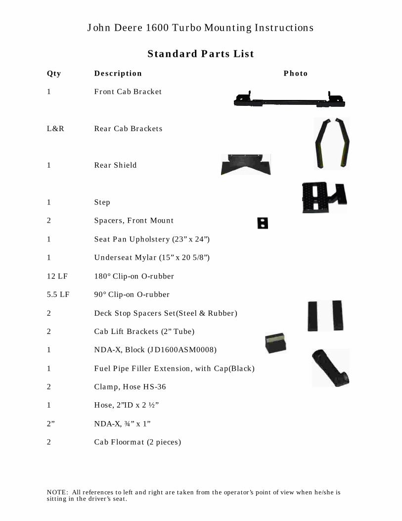
Standard Parts List
Qty Description Photo
1 Front Cab Bracket
L&R Rear Cab Brackets
1 Rear Shield
1 Step
2 Spacers, Front Mount
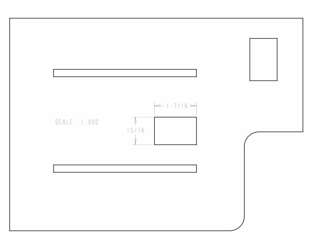
1 Seat Pan Upholstery (23” x 24”)
1 Underseat Mylar (15” x 20 5/8”)
12 LF 180° Clip-on O-rubber
5.5 LF 90° Clip-on O-rubber
2 Deck Stop Spacers Set(Steel & Rubber)
2 Cab Lift Brackets (2” Tube)
1 NDA-X, Block (JD1600ASM0008)
1 Fuel Pipe Filler Extension, with Cap(Black)
2 Clamp, Hose HS-36
1 Hose, 2”ID x 2 ½”
2” NDA-X, ¾” x 1”
2 Cab Floormat (2 pieces)
NOTE: All references to left and right are taken from the operator’s point of view when he/she issitting in the driver’s seat.
John Deere 1600 Turbo Mounting Instructions
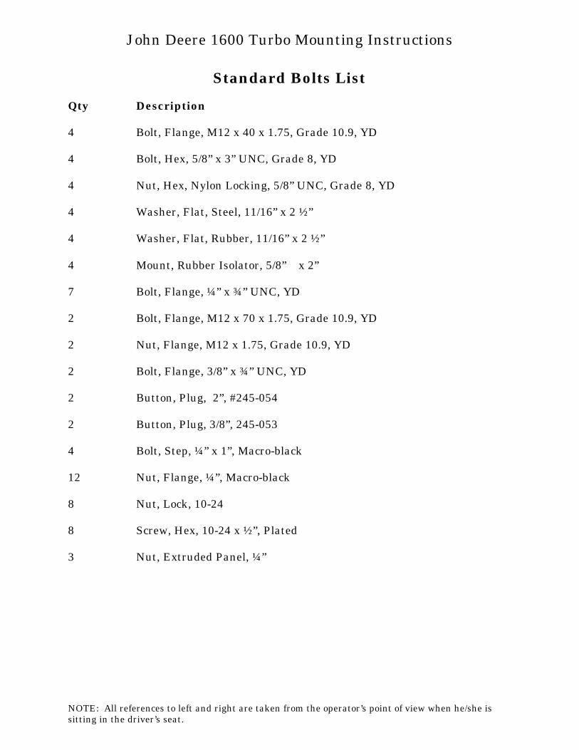
Standard Bolts List
Qty Description
4 Bolt, Flange, M12 x 40 x 1.75, Grade 10.9, YD
4 Bolt, Hex, 5/8” x 3” UNC, Grade 8, YD
4 Nut, Hex, Nylon Locking, 5/8” UNC, Grade 8, YD
4 Washer, Flat, Steel, 11/16” x 2 ½”
4 Washer, Flat, Rubber, 11/16” x 2 ½”
4 Mount, Rubber Isolator, 5/8”∅ x 2”
7 Bolt, Flange, ¼” x ¾” UNC, YD
2 Bolt, Flange, M12 x 70 x 1.75, Grade 10.9, YD
2 Nut, Flange, M12 x 1.75, Grade 10.9, YD
2 Bolt, Flange, 3/8” x ¾” UNC, YD
2 Button, Plug, 2”, #245-054
2 Button, Plug, 3/8”, 245-053
4 Bolt, Step, ¼” x 1”, Macro-black
12 Nut, Flange, ¼”, Macro-black
8 Nut, Lock, 10-24
8 Screw, Hex, 10-24 x ½”, Plated
3 Nut, Extruded Panel, ¼”
NOTE: All references to left and right are taken from the operator’s point of view when he/she issitting in the driver’s seat.
John Deere 1600 Turbo Mounting Instructions
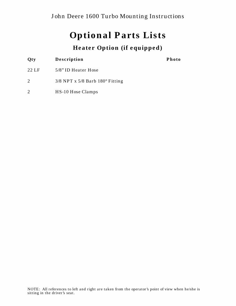
Optional Parts ListsHeater Option (if equipped)
Qty Description Photo
22 LF 5/8” ID Heater Hose
2 3/8 NPT x 5/8 Barb 180° Fitting
2 HS-10 Hose Clamps
NOTE: All references to left and right are taken from the operator’s point of view when he/she issitting in the driver’s seat.
John Deere 1600 Turbo Mounting Instructions
1. Prior to cab installation: ensure tractor has been washed to ensure that floormat,mylar, and upholstery will adhereproperly. Lower all attachments tooperating height before removing anymachinery components, and un-latch andopen hood.
2. Remove 2-post ROPS guard, front deckstop, rear steel firewall, and seat fromseat pan prior to installation.
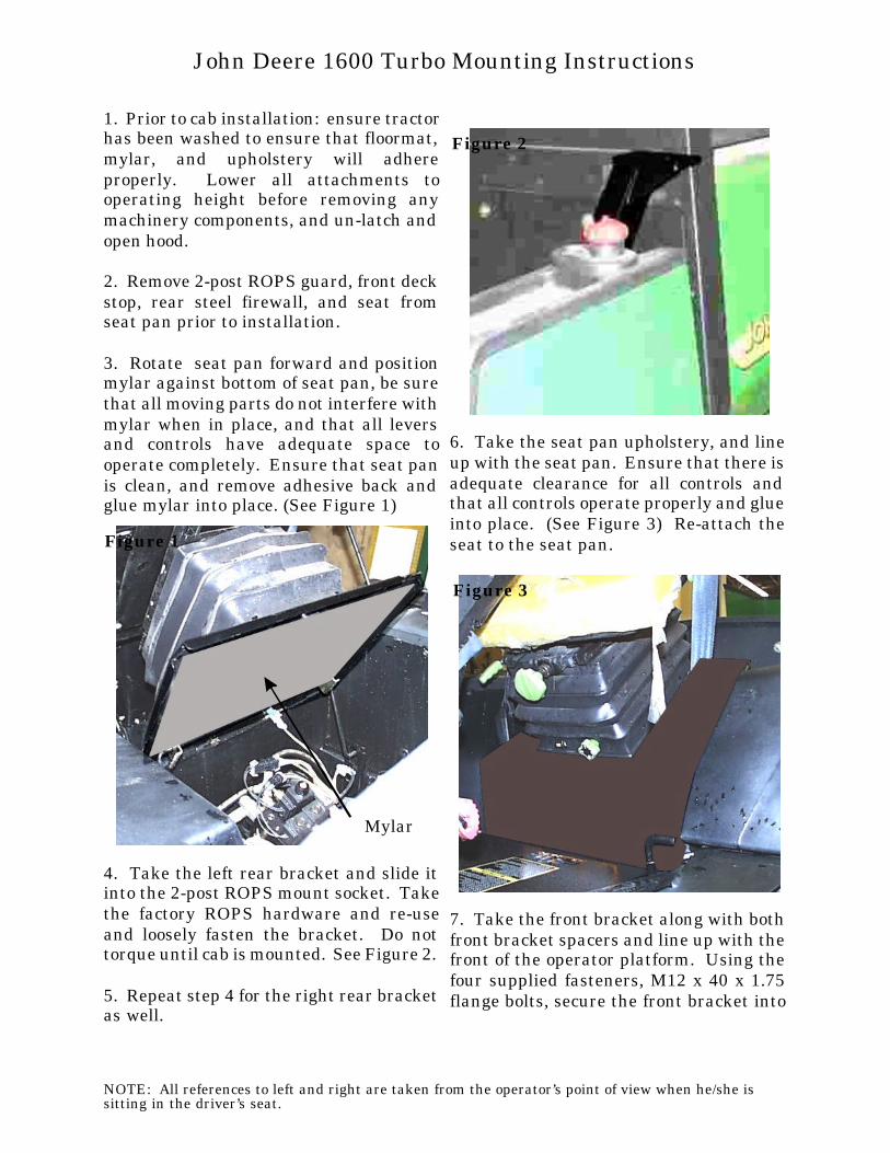
3. Rotate seat pan forward and positionmylar against bottom of seat pan, be surethat all moving parts do not interfere with mylar when in place, and that all leversand controls have adequate space tooperate completely. Ensure that seat panis clean, and remove adhesive back andglue mylar into place. (See Figure 1)
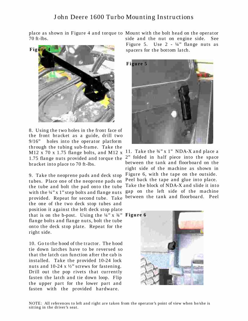
4. Take the left rear bracket and slide itinto the 2-post ROPS mount socket. Takethe factory ROPS hardware and re-useand loosely fasten the bracket. Do nottorque until cab is mounted. See Figure 2.
5. Repeat step 4 for the right rear bracketas well.
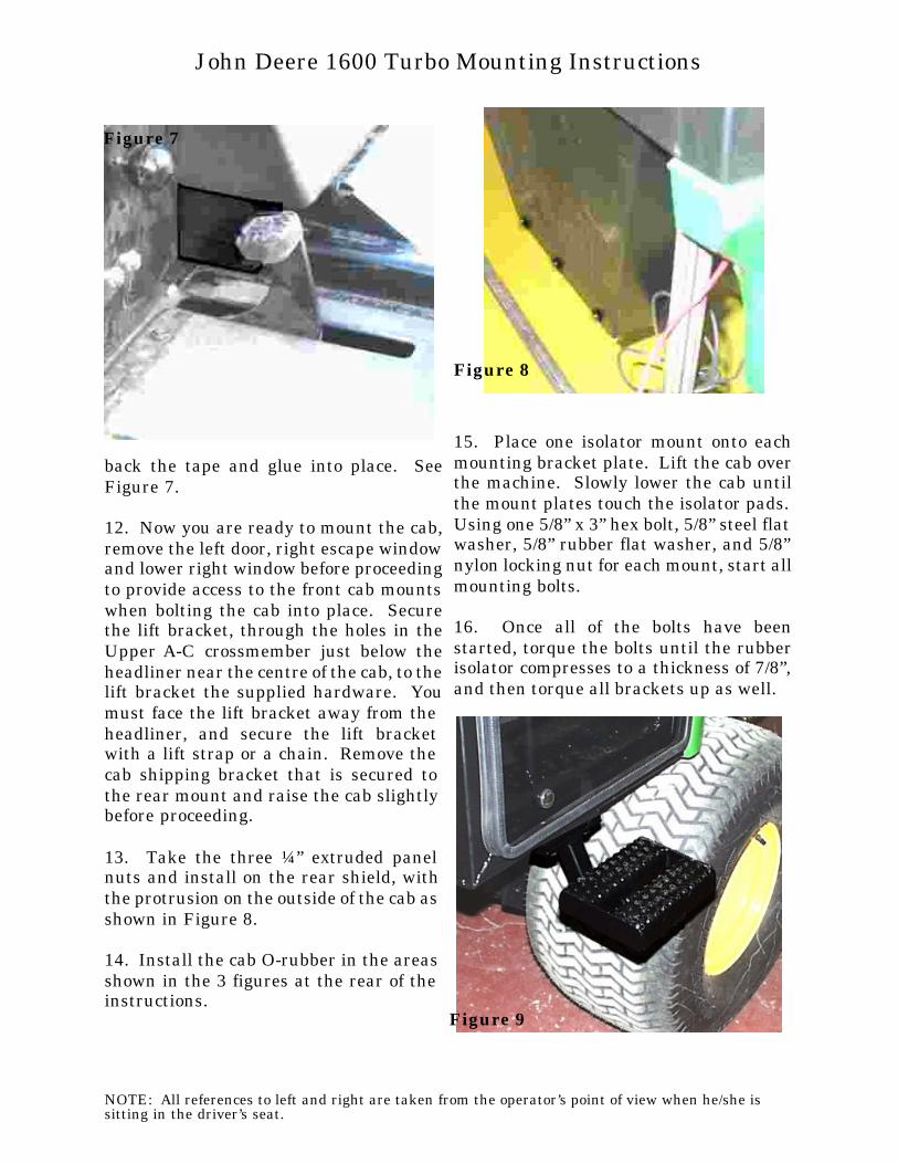
6. Take the seat pan upholstery, and lineup with the seat pan. Ensure that there is adequate clearance for all controls andthat all controls operate properly and glue into place. (See Figure 3) Re-attach theseat to the seat pan.
7. Take the front bracket along with bothfront bracket spacers and line up with thefront of the operator platform. Using thefour supplied fasteners, M12 x 40 x 1.75flange bolts, secure the front bracket into
NOTE: All references to left and right are taken from the operator’s point of view when he/she issitting in the driver’s seat.
John Deere 1600 Turbo Mounting Instructions
Figure 1
Mylar
Figure 2
Figure 3
place as shown in Figure 4 and torque to70 ft-lbs.
8. Using the two holes in the front face ofthe front bracket as a guide, drill two9/16”∅ holes into the operator platformthrough the tubing sub-frame. Take theM12 x 70 x 1.75 flange bolts, and M12 x1.75 flange nuts provided and torque thebracket into place to 70 ft-lbs.
9. Take the neoprene pads and deck stoptubes. Place one of the neoprene pads onthe tube and bolt the pad onto the tubewith the ¼” x 1” step bolts and flange nutsprovided. Repeat for second tube. Takethe one of the two deck stop tubes andposition it against the left deck stop platethat is on the b-post. Using the ¼” x ¾”flange bolts and flange nuts, bolt the tubeonto the deck stop plate. Repeat for theright side.
10. Go to the hood of the tractor. The hood tie down latches have to be reversed sothat the latch can function after the cab isinstalled. Take the provided 10-24 locknuts and 10-24 x ½” screws for fastening. Drill out the pop rivets that currentlyfasten the latch and tie down loop. Flipthe upper part for the lower part andfasten with the provided hardware.
Mount with the bolt head on the operatorside and the nut on engine side. SeeFigure 5. Use 2 - ¼” flange nuts asspacers for the bottom latch.
11. Take the ¾” x 1” NDA-X and place a2” folded in half piece into the spacebetween the tank and floorboard on theright side of the machine as shown inFigure 6, with the tape on the outside. Peel back the tape and glue into place. Take the block of NDA-X and slide it intogap on the left side of the machinebetween the tank and floorboard. Peel
NOTE: All references to left and right are taken from the operator’s point of view when he/she issitting in the driver’s seat.
John Deere 1600 Turbo Mounting Instructions
Figure 4
Figure 5
Figure 6
back the tape and glue into place. SeeFigure 7.
12. Now you are ready to mount the cab,remove the left door, right escape windowand lower right window before proceedingto provide access to the front cab mountswhen bolting the cab into place. Securethe lift bracket, through the holes in theUpper A-C crossmember just below theheadliner near the centre of the cab, to the lift bracket the supplied hardware. Youmust face the lift bracket away from theheadliner, and secure the lift bracketwith a lift strap or a chain. Remove thecab shipping bracket that is secured tothe rear mount and raise the cab slightlybefore proceeding.
13. Take the three ¼” extruded panelnuts and install on the rear shield, withthe protrusion on the outside of the cab as shown in Figure 8.
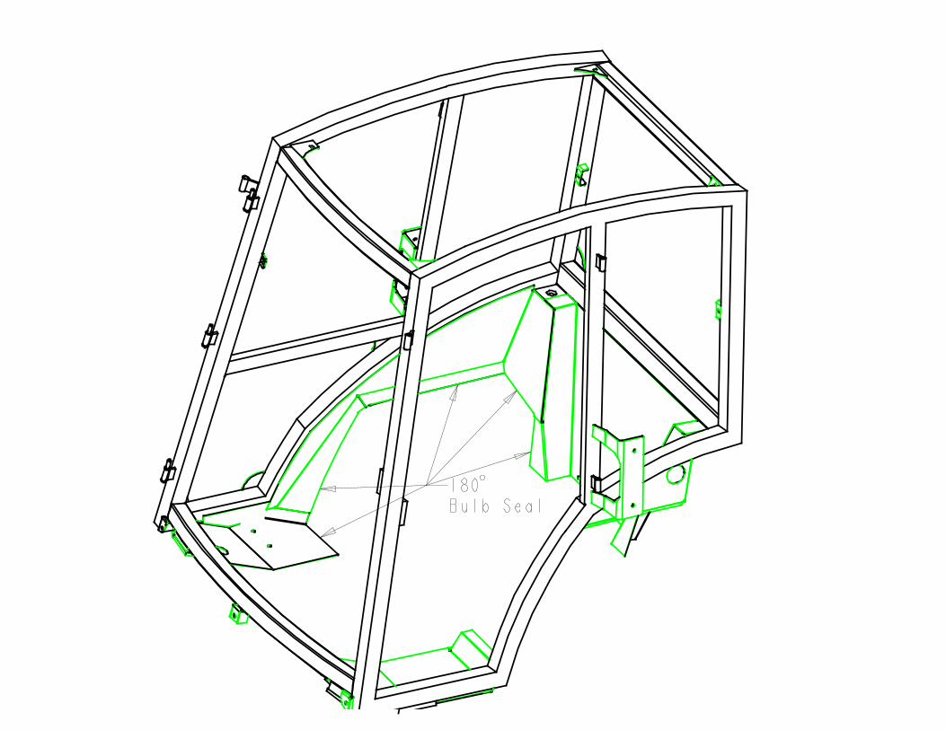
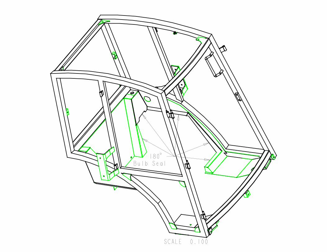
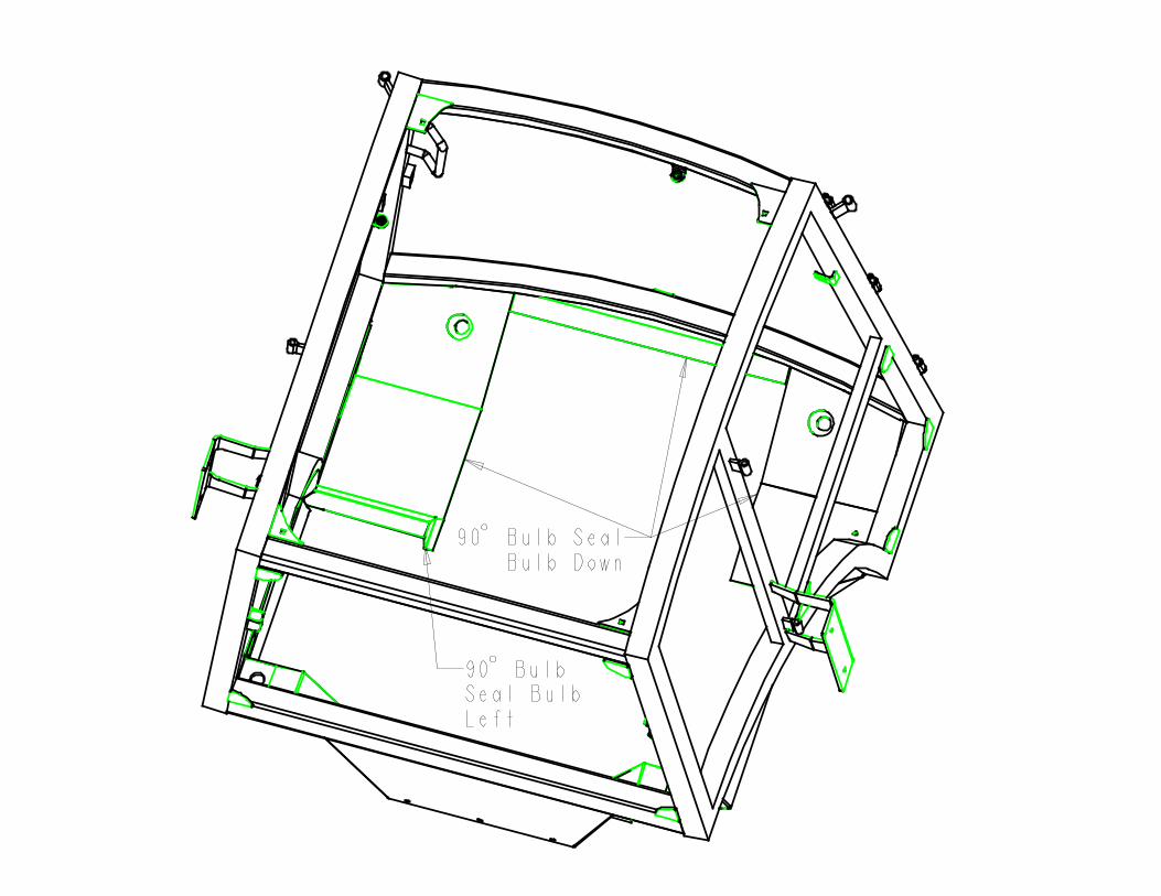
14. Install the cab O-rubber in the areasshown in the 3 figures at the rear of theinstructions.
15. Place one isolator mount onto eachmounting bracket plate. Lift the cab overthe machine. Slowly lower the cab untilthe mount plates touch the isolator pads. Using one 5/8” x 3” hex bolt, 5/8” steel flatwasher, 5/8” rubber flat washer, and 5/8”nylon locking nut for each mount, start allmounting bolts.
16. Once all of the bolts have beenstarted, torque the bolts until the rubberisolator compresses to a thickness of 7/8”,and then torque all brackets up as well.
NOTE: All references to left and right are taken from the operator’s point of view when he/she issitting in the driver’s seat.
John Deere 1600 Turbo Mounting Instructions
Figure 7
Figure 8
Figure 9
17. Remove the cab lift bracket and snapthe two 3/8” plug buttons into the holes inthe outside of the tubing.
18. Install the two 2” plug buttons in theplatform extension above the front cabmounts before gluing in the floormat.
19. Re-install the lower right window,right escape window and left door.
20. Take the step, and the two 3/8” x ¾”flange bolts and fasten the step to thebottom of the cab frame at the centre ofthe door to the plate underneath the cabframe as shown in Figure 9.
21. Locate the wires coming out of theC-post. Connect the heavy read wire to12V. Connect the heavy black wire totractor ground. Connect the orange wireto a switch source on the tractor.
If cab is equipped with the heater option,follow steps 22 & 23.
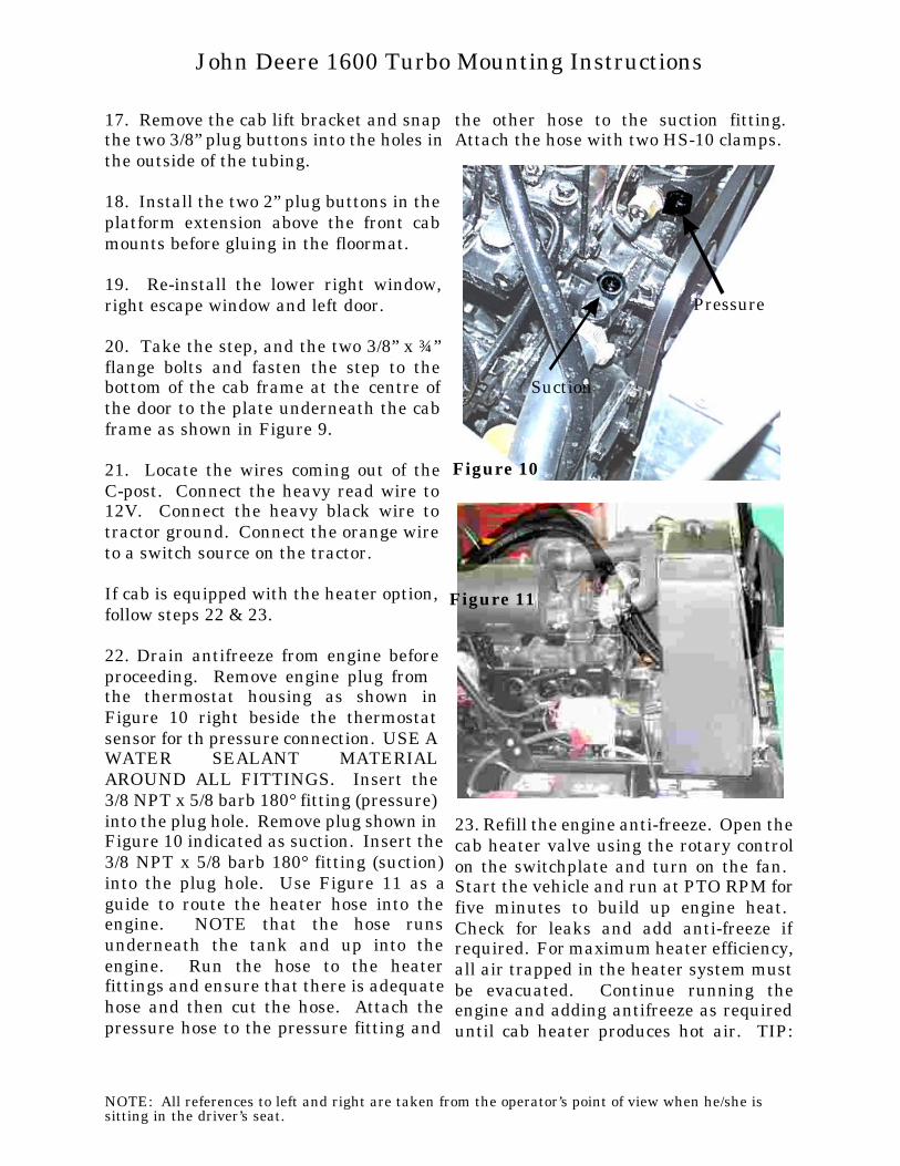
22. Drain antifreeze from engine beforeproceeding. Remove engine plug from the thermostat housing as shown inFigure 10 right beside the thermostatsensor for th pressure connection. USE A WATER SEALANT MATERIALAROUND ALL FITTINGS. Insert the3/8 NPT x 5/8 barb 180° fitting (pressure)into the plug hole. Remove plug shown in Figure 10 indicated as suction. Insert the3/8 NPT x 5/8 barb 180° fitting (suction)into the plug hole. Use Figure 11 as aguide to route the heater hose into theengine. NOTE that the hose runsunderneath the tank and up into theengine. Run the hose to the heaterfittings and ensure that there is adequatehose and then cut the hose. Attach thepressure hose to the pressure fitting and
the other hose to the suction fitting. Attach the hose with two HS-10 clamps.
23. Refill the engine anti-freeze. Open the cab heater valve using the rotary controlon the switchplate and turn on the fan. Start the vehicle and run at PTO RPM forfive minutes to build up engine heat. Check for leaks and add anti-freeze ifrequired. For maximum heater efficiency, all air trapped in the heater system mustbe evacuated. Continue running theengine and adding antifreeze as requireduntil cab heater produces hot air. TIP:
NOTE: All references to left and right are taken from the operator’s point of view when he/she issitting in the driver’s seat.
John Deere 1600 Turbo Mounting Instructions
Pressure
Suction
Figure 10
Figure 11

when purging system of air, open radiatorcap when running the engine.
24. Take the rear shield (pre-upholstered) and install 180D O-rubber along on theedge shown in Figure 12. Take the shieldand the ¼” x ¾” flange bolts and go intothe cab and install the shield in the rear. Bolt the shield to the back wall of the cabwith the fasteners provided.
25. Take the main cab floormat and placeit onto the platform floor. Make sure thatthere is adequate pedal clearance, andthen glue the floormat into position. Takethe front cab panel floormat and positionit along the front edge of the cab and thenglue into place.
NOTE: All references to left and right are taken from the operator’s point of view when he/she issitting in the driver’s seat.
John Deere 1600 Turbo Mounting Instructions
Figure 12

Electrical Connectors List
Qty Description
2 Connectors, Loop, 10GA, ¼”
1 Connectors, Loop, 10GA, ½”
1 Connectors, Loop, 10GA, 3/8”
1 Splicer, Wire, Blue
NOTE: All references to left and right are taken from the operator’s point of view when he/she issitting in the driver’s seat.
ADDENDUM ALL Mounting Instructions