Embed Size (px)
Citation preview
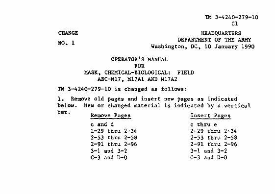
TM 3-4240-279-10
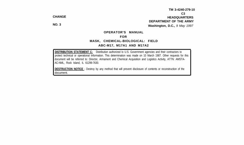
CHANGE
NO. 3
TM 3-4240-279-10C3
HEADQUARTERSDEPARTMENT OF THE ARMYWashington, D.C., 9 May 1997
OPERATOR’S MANUALFOR
MASK, CHEMICAL-BIOLOGICAL: FIELDABC-M17, M17A1 AND M17A2
DISTRIBUTION STATEMENT C: Distribution authorized lo U.S. Government agencies and their contractors toprotect technical or operational Information. This determination was made on 10 March 1987. Other requests for thisdocument will be referred to: Director, Armament and Chemical Acquisition and Logistics Activity, ATTN: AMSTA-AC-NML, Rock Island, IL 61299-7630.
DESTRUCTION NOTlCE - Destroy by any method that will prevent disclosure of contents or reconstruction of thedocument.
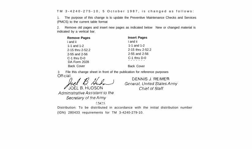
T M 3 - 4 2 4 0 - 2 7 5 - 1 0 , 5 O c t o b e r 1 9 8 7 , i s c h a n g e d a s f o l l o w s :
1. The purpose of this change is lo update the Preventive Maintenance Checks and Services(PMCS) to the current table format
2. Remove old pages and insert new pages as indicated below New or changed material isindicated by a vertical bar.
Remove Pages Insert Pagesi and ii i and ii1-1 and 1-2 1-1 and 1-22-15 thru 2-52.2 2-15 thru 2-52.22-55 and 2-56 2-55 and 2-56C-1 thru D-0 C-1 thru D-0DA Form 2028 - - - - - - -
Back Cover Back Cover
3 File this change sheet in front of the publication for reference purposes
Distribution: To be distributed in accordance with the initial distribution number
(IDN) 280433 requirements for TM 3-4240-279-10.
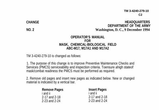
TM 3-4240-279-10C2
CHANGE
NO. 2
HEADQUARTERSDEPARTMENT OF THE ARMY
Washington, D. C., 9 December 1994
OPERATOR’S MANUALFOR
MASK, CHEMICAL-BIOLOGICAL FIELDABC-M17, M17A1 AND M17A2
TM 3-4240-279-10 is changed as follows:
1. The purpose of this change is to improve Preventive Maintenance Checks andServices (PMCS) serviceability and inspection criteria. Toensure ahigh stateofmask/combat readiness the PMCS must be performed as required.
2. Remove old pages and insert new pages as indicated below. New or changedmaterial is indicated by a vertical bar.
Remove Pages Insert Pagesi and ii i and ii2-17 and 2-18 2-17 and 2-182-23 and 2-24 2-23 and 2-24
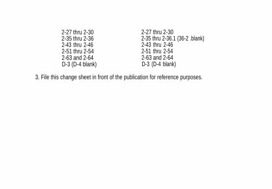
2-27 thru 2-30 2-27 thru 2-302-35 thru 2-36 2-35 thru 2-36.1 (36-2 .blank)2-43 thru 2-46 2-43 thru 2-462-51 thru 2-54 2-51 thru 2-542-63 and 2-64 2-63 and 2-64D-3 (D-4 blank) D-3 (D-4 blank)
3. File this change sheet in front of the publication for reference purposes.
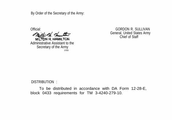
By Order of the Secretary of the Army:
Official:
Administrative Assistant to theSecretary of the Army
07830
DISTRIBUTION :
GORDON R. SULLIVANGeneral, United States Army
Chief of Staff
To be distributed in accordance with DA Form 12-28-E,block 0433 requirements for TM 3-4240-279-10.
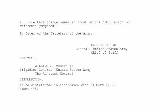
2. File this change sheet in front of the publication forreference purposes.
By Order of the Secretary of the Army:
CARL E. VUONOGeneral, United States Army
Chief of Staff
OFFICIAL:
WILLIAM J. MEEHAN IIBrigadier General, United States Army
The Adjutant General
DISTRIBUTION:
To be distributed in accordance with DA Form 12-28,block 433.
a
TM 3-4240-279-10
WARNING
The M17/M17A1/M17A2 masks will not protect the wearer against ammoniaor carbon monoxide gases. The masks will not protect the wearer in confinedspacces where the oxygen content of the air is too low.
Stop breathing when putting on your facepiece assembly. Toxic agents maybe in the surrounding air. Do the steps for putting on your facepiec quickly.You must don, clear, and check your facepiece before you take anotherbreath.
The facepiece must be checked for leaks when it is initially fitted and eachtime it is used. A leaky facepiece will not protect you from toxic agents.
If you become overheated in very cold weather, do not remove your face-piece outdoors until your head cools and any sweat has dried. Frostbite, orother cold weather injury, may result if the facepiece is removed and the faceis not immediately dried.
In cold weather, do not clear the facepiece by exhaling a large volume of air.Most air will frost eyelenses and impair vision.
b
WARNING (CONT)
Do not wear contact lenses when wearing optical inserts. Contact lenses willovercorrect vision while wearing optical inserts.
Keep mask dry, Moisture could clog the filter elements and make the facepieceuseless.
Any solid matter (even grass) under facepiece valve disks will cause foggedeyelenses, discomfort, and leakage.
Dirt or other foreign material on the connectors of filter elements, mating surfacesof the faceblank, or trapped between these surfaces lets contaminated air intoyour facepiece.
Do not use the facepiece if inlet valves, valve disks, or outlet valve disks aredamaged, missing, or improperly installed. Facepiece may leak.
DS2 can damage the voicemitter of the mask, If the voicemitter has been contami-nated with DS2, immediately splash the voicemitter three times with clean water.Do not wet the filter elements.
TM 3-4740-279-10WARNING (CONT)
In toxic atmosphere, do not break the seal between your hood and facepeiceand the side of your face when putting on your headgear. This could causethe facepiece to leak.
Keep face clean shaven. An unshaven face could cause a bad seal betweenface and facepiece.
Female soldiers shall remove all hairpens, combs, hair knots, buns, or braidsthat will interfere with facepiece seal.
Do not connect the quick disconnect coupling half to your canteen until allmating surfaces have been checked for chemical contamination. Chemicalagents can enter your mouth, resulting in sickness or death.
If resistance is not felt when checking Ml7AI/M17A2 mask drinking system,your drinking system leaks. Do not drink; get a new mask.
Change 1 c
WARNING (CONT)
When using sanitizing solution. avoid eye and facial area contact, If contactoccurs. flush with water and seek medical attention.
Because of toxic effects, the M1 waterproof bag should not contact food stuffs
FIRST AIDFor first aid, refer to FM 21-11
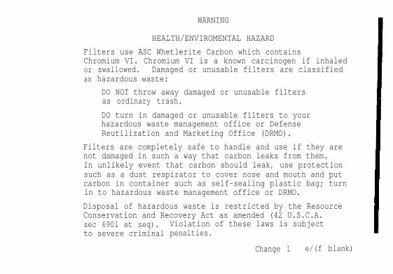
WARNING
HEALTH/ENVIROMENTAL HAZARD
Filters use ASC Whetlerite Carbon which containsChromium VI. Chromium VI is a known carcinogen if inhaledoras
swallowed. Damaged or unusable filters are classifiedhazardous waste:
DO NOT throw away damaged or unusable filtersas ordinary trash.
DO turn in damaged or unusable filters to yourhazardous waste management office or DefenseReutilization and Marketing Office (DRMO).
Filters are completely safe to handle and use if they arenot damaged in such a way that carbon leaks from them.In unlikely event that carbon should leak, use protectionsuch as a dust respirator to cover nose and mouth and putcarbon in container such as self-sealing plastic bag; turnin to hazardous waste management office or DRMO.
Disposal of hazardous waste is restricted by the ResourceConservation and Recovery Act as amended (42 U.S.C.A.sec 6901 et seq).to severe criminal
Violation of these laws is subjectpenalties.
Change 1 e/(f blank)
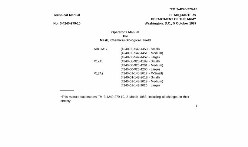
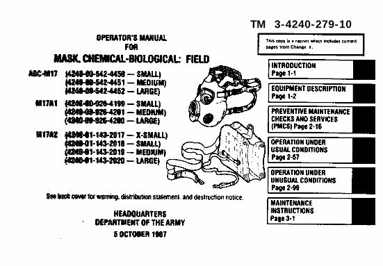
Technical Manual
No. 3-4240-279-10
*TM 3-4240-279-10
HEADQUARTERSDEPARTMENT OF THE ARMY
Washington, D.C., 5 October 1987
Operator’s ManualFor
Mask, Chemical-Biological: Field
ABC-M17
M17A1
M17A2
(4240-00-542-4450 - Small)(4240-00-542-4451 - Medium)(4240-00-542-4452 - Large)(4240-00-926-4199 - Small)(4240-00-926-4201 - Medium)(4240-00-926-4200 - Large)(4240-01-143-2017 - X-Small)(4240-01-143-2018 - Small)(4240-01-143-2019 - Medium)(4240-01-143-2020 Large)
*This manual supersedes TM 3-4240-279-10, 2 March 1983, including all changes in theirentirety
i
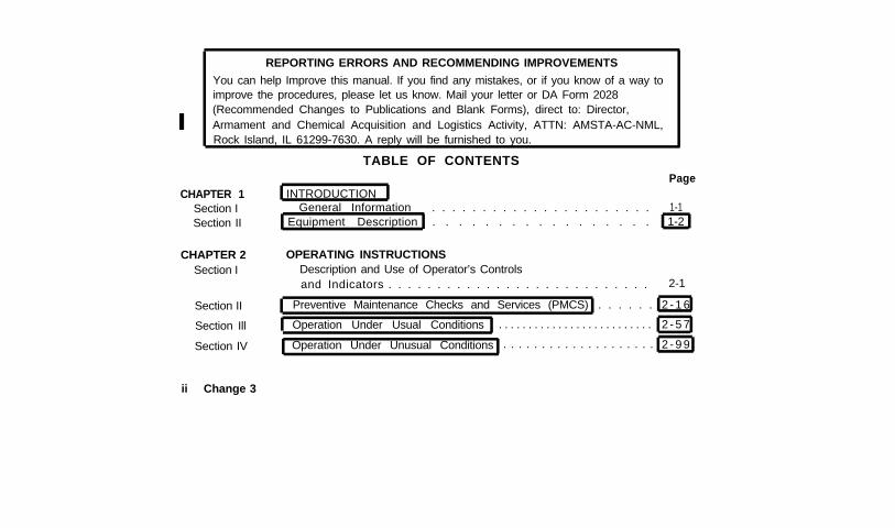
REPORTING ERRORS AND RECOMMENDING IMPROVEMENTS
You can help Improve this manual. If you find any mistakes, or if you know of a way toimprove the procedures, please let us know. Mail your letter or DA Form 2028(Recommended Changes to Publications and Blank Forms), direct to: Director,Armament and Chemical Acquisition and Logistics Activity, ATTN: AMSTA-AC-NML,Rock Island, IL 61299-7630. A reply will be furnished to you.
TABLE OF CONTENTS
CHAPTER 1Section ISection II
CHAPTER 2Section I
Section II
Section Ill
Section IV
ii Change 3
INTRODUCTIONPage
General Information . . . . . . . . . . . . . . . . . . . . . . 1-1Equipment Description . . . . . . . . . . . . . . . . . 1-2
OPERATING INSTRUCTIONSDescription and Use of Operator’s Controlsand Indicators . . . . . . . . . . . . . . . . . . . . . . . . . . . 2-1
Preventive Maintenance Checks and Services (PMCS) . . . . . . 2 - 1 6
Operation Under Usual Conditions . . . . . . . . . . . . . . . . . . . . . . . . . . 2 - 5 7
Operation Under Unusual Conditions . . . . . . . . . . . . . . . . . . . . 2 - 9 9
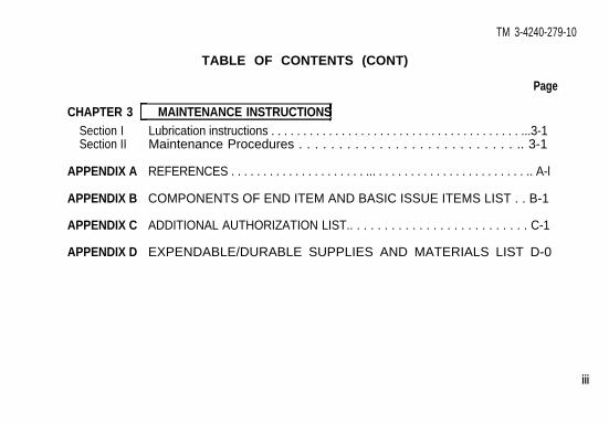
TM 3-4240-279-10
TABLE OF CONTENTS (CONT)
Page
CHAPTER 3 MAINTENANCE INSTRUCTIONSSection ISection II
APPENDIX A
APPENDIX B
APPENDIX C
APPENDIX D
Lubrication instructions . . . . . . . . . . . . . . . . . . . . . . . . . . . . . . . . . . . . . . . ...3-1Maintenance Procedures . . . . . . . . . . . . . . . . . . . . . . . . . . . .. 3-1
REFERENCES . . . . . . . . . . . . . . . . . . . . . ... . . . . . . . . . . . . . . . . . . . . . . . .. A-l
COMPONENTS OF END ITEM AND BASIC ISSUE ITEMS LIST . . B-1
ADDITIONAL AUTHORIZATION LIST.. . . . . . . . . . . . . . . . . . . . . . . . . . C-1
EXPENDABLE/DURABLE SUPPLIES AND MATERIALS LIST D-0
iii
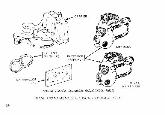
1-0
CHAPTER 1
INTRODUCTION
TM 3-4240-279-10
Section I. GENERAL INFORMATION
1-1. SCOPE.
a. Type of Manual. Operator’s Manualb. Model Numbers and Equipment Names. ABC-M17/M17A1/M17A2 Mask, Chemical-
Biological: Fieldc. Purpose of Equipment The mask protects your face, eyes, and lungs from field
concentrations of chemical-biological (CB) agents and not control (RC) agents.d. Special Limitations on Equipment. The mask does not protect the wearer against ammonia
or carbon monoxide gases Also it is not effective in confined spaces where oxygen content of theair is too low.
1-2. MAINTENANCE FORMS AND RECORDS.
Department of the Army forms and procedures used for equipment maintenance will be thoseprescribed by DA PAM 738-750. The Army Maintenance Management System (TAMMS).
1-1
1-3. REPORTING EQUIPMENT IMPROVEMENT RECOMMENDATIONS (EIRS).
If your M17/M17A1/M17A2 mask needs improvements let us know Send us an EIR You, the user,are the only one who can tell us what you don’t like about your equipment. Let us know why youdon’t like the design Put it on an SF Form 368 (Quality Deficiency Report). Mail it to us atCommander, U.S. Army Armament Research, Development and Engineering Center, ATTN:AMSTA-AR-QAW-A(R)/Customer Feedback Center, Rock Island, IL 61299-7300. We’ll send you a
reply.
Section II. EQUIPMENT DESCRIPTION
1-4. EQUIPMENT PURPOSE, CAPABILITIES, AND FEATURES.
a. Purpose. The mask is used as an individual respiratory protection device.b. Capabilities. When worn with the proper filter elements installed, the mask protects face,
eyes and lungs from field concentrations of chemical-biological (CB) agents and riot control (RC)agents
1-2 Change 3
TM 3-4240-279-10
WARNINGThe M17/M17A1/M17A2 mask will not protect the wearer against ammonia orcarbon monoxide gases. It is not effective in confined spaces where the oxygencontent of the air IS too low.
c. Features. Major features of the mask area rubber faceblank which provides a sealagainst agents, two replaceable filter elements which filter particulate matter and agents from air,and a voicemitter-outlet valve assembly which transmits the user’s voice outside the mask.
1-5. DIFFERENCES BETWEEN MODELS
a. Throughout this manual, the term “mask” refers to the M17, M17A1, and M17A2 masks.When data applies to one model only, the model will be specifically identified,
b. The M17, M17A1, and M17A2 masks are identical, except the Ml7A1/M17A2 maskshave three additional features. The voicemitter-outlet valve assemblies for the M17A1/M17A2masks are equipped with a drinking system while the Ml 7 mask is not equipped with this system.The M17A1/M17A2 masks also have molded-in mounting points for prong t ypa optical inserts.The M17A2 mask is available in one additional size (extra small). Early style extra small maskshave a full inturned lip while the later style (NSN 4240-01-1 43-2017) has a 3/4 inturned lip.
1-3
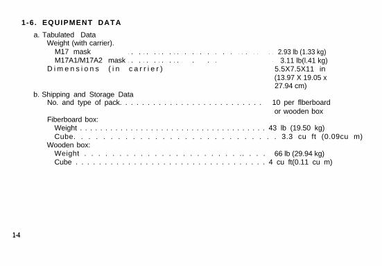
1-6. EQUIPMENT DATA
a. Tabulated DataWeight (with carrier).
M17 mask 2.93 lb (1.33 kg)M17A1/M17A2 mask 3.11 lb(l.41 kg)
D i m e n s i o n s ( i n c a r r i e r ) 5.5X7.5X11 in(13.97 X 19.05 x27.94 cm)
b. Shipping and Storage DataNo. and type of pack. . . . . . . . . . . . . . . . . . . . . . . . . . 10 per flberboard
or wooden boxFiberboard box:
Weight . . . . . . . . . . . . . . . . . . . . . . . . . . . . . . . . . . . . . 43 lb (19.50 kg)Cube. . . . . . . . . . . . . . . . . . . . . . . . . . . . 3.3 cu ft (0.09cu m)
Wooden box:Weight . . . . . . . . . . . . . . . . . . . . . . .. . . . 66 lb (29.94 kg)Cube . . . . . . . . . . . . . . . . . . . . . . . . . . . . . . . . . 4 cu ft(0.11 cu m)
1-4
TM 3-4240-279-10
CHAPTER 2OPERATING INSTRUCTIONS
Section I. DESCRIPTION AND USE OFOPERATOR’S CONTROLS AND INDICATORS
2-1. GENERALa. Before attempting to use the mask and additionally authorized items, make certain you
are familiar with the location and operation of all parts.b. Functions of NBC NCO may be performed by first line supervisors.
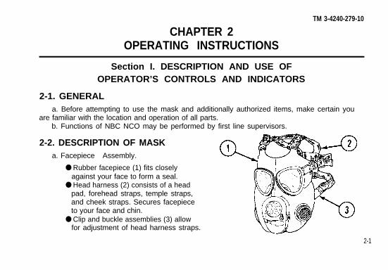
2-2. DESCRIPTION OF MASKa. Facepiece Assembly.
● Rubber facepiece (1) fits closelyagainst your face to form a seal.
● Head harness (2) consists of a headpad, forehead straps, temple straps,and cheek straps. Secures facepieceto your face and chin.
● Clip and buckle assemblies (3) allowfor adjustment of head harness straps.
2-1
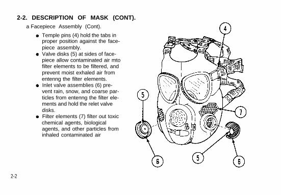
2-2. DESCRIPTION OF MASK (CONT).a Facepiece Assembly (Cont).
Temple pins (4) hold the tabs inproper position against the face-piece assembly.Valve disks (5) at sides of face-piece allow contaminated air mtofilter elements to be filtered, andprevent moist exhaled air fromentenng the filter elements.Inlet valve assemblies (6) pre-vent rain, snow, and coarse par-ticles from entenng the filter ele-ments and hold the relet valvedisks.Filter elements (7) filter out toxicchemical agents, biologicalagents, and other particles frominhaled contaminated air
2-2
TM 3-4240-279-10
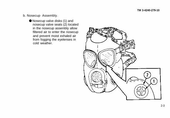
b. Nosecup Assembly.
● Nosecup valve disks (1) andnosecup valve seats (2) locatedin the nosecup assembly allowfiltered air to enter the nosecupand prevent moist exhaled airfrom fogging the eyelenses incold weather.
2-3
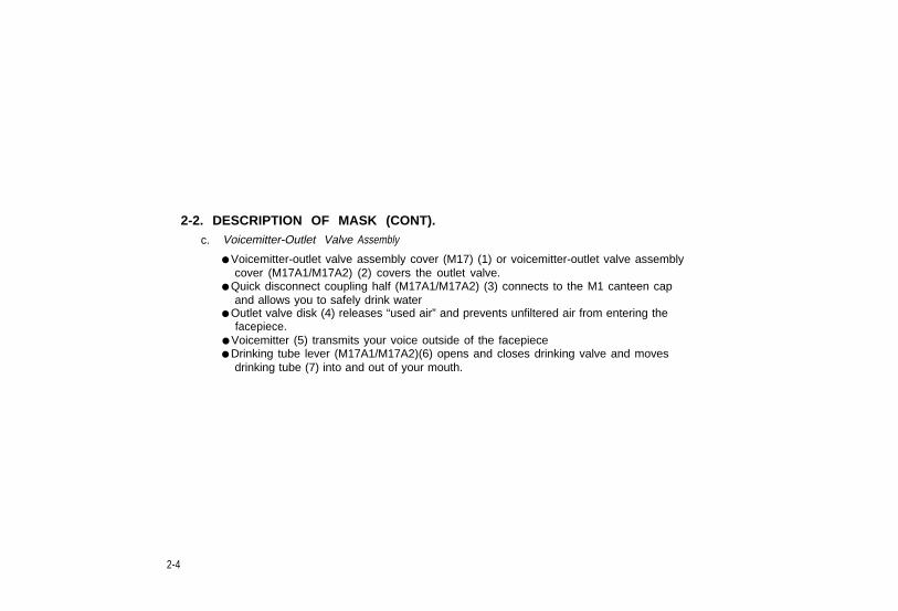
2-2. DESCRIPTION OF MASK (CONT).c. Voicemitter-Outlet Valve Assembly
● Voicemitter-outlet valve assembly cover (M17) (1) or voicemitter-outlet valve assemblycover (M17A1/M17A2) (2) covers the outlet valve.
● Quick disconnect coupling half (M17A1/M17A2) (3) connects to the M1 canteen capand allows you to safely drink water
● Outlet valve disk (4) releases “used air” and prevents unfiltered air from entering thefacepiece.
● Voicemitter (5) transmits your voice outside of the facepiece● Drinking tube lever (M17A1/M17A2)(6) opens and closes drinking valve and moves
drinking tube (7) into and out of your mouth.
2-4
TM 3-4240-279-10
2-5
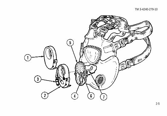
2-2. DESCRIPTION OF MASK (CONT).d. Carrier
Provides for storage and carryingof facepiece and additionallyauthorized items.Consists of upper pocket (1),lower outside pocket (2), insidepocket (3), bottom pocket* (4),shoulder strap (5), waist strap (6),and quick-opening flap (7).Quick-opening flap (7) providesready access to the carrier’scontents.
Later models of carrier will not havebottom pocket.
2-6
TM 3-4240-279-10
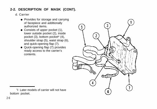
e. M1 Waterproof Bag
WARNINGBecause of possible toxic effects, thisbag should not contact food.
CAUTIONStorage of facepiece in this bag candegrade its protective capability. Usebag only for brief periods to protectfacepiece from immersion in water,such as when fording streams. Removefacepiece from bag as soon as protec-tion is no longer required.
● Keeps facepiece dry when required by cli-mate and mission.
● Includes rubberband for closure.● Bag is stowed in carrier.
2-7

2-2. DESCRIPTION OF MASK (CONT).
f. Eyelens Outserts
Rubber rings (1) fit over facepieceeyelens crimping rings to securethe eyelens outserts to the face-
Transparent plastic lenses (2) pro-tect eyelens from scratches andother damage.The eyelens outserts prevent eye-Iens from fogging in cold weather.
2-8
2-3.
a.
DESCRIPTION OF ADDITIONALL
ABC-M6A2 Hood.
● The ABC-M6A2 hood is made ofrubber-coated fabric, which pro-tects the neck and areas of headnot covered by your facepieceagainst CB agents.
● Eyering openings (1), voicemitter-outlet valve assembly cover open-ing (2), and inlet valve assemblyopenings (3) provide unobstructedvision and breathing.
TM 3-4240-279-10
Y AUTHORIZED ITEMS (APP C).
2-9
2-3. DESCRIPTION OF ADDITIONALLY AUTHORIZED ITEMS (APP C) (CONT).
a. ABC-M6A2 Hood (Cont)
Cord (4) draws the hood close toneck by using slider (5).Zipper (6) permits the hood to openfor ventilation or close for protec-tion in accordance with MOPPrequirements.Underarm straps (7) keep cape (8)and bib (9) down on the shoulders.Underarm straps are fastened onfastening cloth (10).Hook and pile fastener (11 ) holdsthe hood open for ventilation whenMOPP permits
2-10
TM 3-4240-279-10
b. M4 Winterization Kit.
The M4 kit is worn when the temperature is 20° F (-7°C) or below. However, the kitmay be used when the temperature is above 200F (-7°C), or if temperatures areexpected to drop to that level.Prefilter (1) prevents frost from accumulating on inlet valve assemblies during subzeroweather.Tape (2) positions on top of voicemitter-outlet valve assembly cover to assist in aliningprefilter (1).Retainers (3) lock prefilter (1) to the inlet valve assemblies.The M4 kit is stored in the inside pocket of the carrier.Hook and pile fastener (4) holds prefilter (1 ) in position over the facepiece inlet valveassemblies, and retainers (3).The M4 kit is a close-fit on a facepiece with the M6A2 hood installed. Some time andcare must be spent fitting the kit retainers (3) around the inlet valve assemblies.
2-11
2-3. DESCRIPTION OF ADDITIONALLY AUTHORIZED ITEMS (APP C) (CONT).c. Optical Inserts.
WARNINGDo not wear contact lenses when wearingoptical inserts. Contact lenses will overcor-rect Vision while wearing optical inserts.
● Optical inserts are available by medical pre-scription for personnel who must wearglasses.
● Wire frame optical inserts (1) fit M17 andM17A1/M17A2 masks.
NOTEWire frame inserts have small screws thatmay become loose If they do ask a techni-cian in your troop medical unit to tightenthem and apply a drop of adhesive or clearnail polish to prevent screws from loosen-ing again.
● Prong type optical inserts (2) with plasticframes fit only the M17A1/M17A2 masks.
2-12
TM 3-4240-279-10
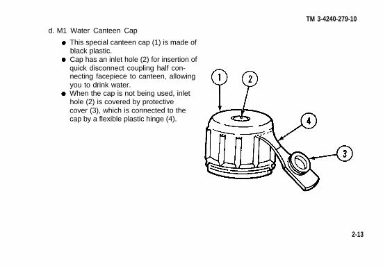
d. M1 Water Canteen Cap
This special canteen cap (1) is made ofblack plastic.Cap has an inlet hole (2) for insertion ofquick disconnect coupling half con-necting facepiece to canteen, allowingyou to drink water.When the cap is not being used, inlethole (2) is covered by protectivecover (3), which is connected to thecap by a flexible plastic hinge (4).
2-13
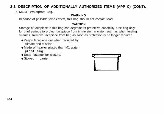
2-3. DESCRIPTION OF ADDITIONALLY AUTHORIZED ITEMS (APP C) (CONT).e. M1A1 Waterproof Bag.
WARNINGBecause of possible toxic effects, this bag should not contact food
CAUTIONStorage of facepiece in this bag can degrade its protective capability. Use bag onlyfor brief periods to protect facepiece from immersion in water, such as when fordingstreams. Remove facepiece from bag as soon as protection is no longer required.
● Keeps facepiece dry when required byclimate and mission.
● Made of heavier plastic than M1 water-p r o o f b a g .
● Snap fastener for closure.● Stowed in carrier.
2-14
TM 3-4240-279-10
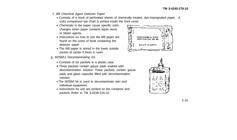
f. M8 Chemical Agent Detector PaperConsists of a book of perforated sheets of chemically treated, dye-impregnated paper. Acolor comparison bar chart is printed inside the front cover.Chemicals in the paper cause specific colorchanges when paper contacts liquid nerveor blister agents.Instructions on how to use the M8 paper arefound on the cover of book containing thedetector paperThe M8 paper is stored in the lower outsidepocket of carrier if there is room
g. M258A1 Decontaminating Kit.
Consists of six packets in a plastic caseThree packets contain gauze pads soaked withdecontamination solution Three packets contain gauzepads and glass capsules filled with decontaminationsolution
The M258A kit is used to decontaminate skin andindividual equipment.Instructions for use are printed on the container andpackets Refer to TM 3-4230-216-10.
2-15
Section II. PREVENTIVE MAINTENANCE CHECKSAND SERVICES (PMCS)
2-4. GENERAL.
a. Before you Operate. Always keep in mind CAUTIONS and WARNINGS. Perform yourBEFORE PMCS on all missions.
b After you Operate. Be sure to perform your AFTER PMCS on all missions.c. Weekly (in combat situations). Be sure to perform your WEEKLY PMCS in combat-ready
situations only.
2-5. PREVENTIVE MAINTENANCE CHECKS AND SERVICES (PMCS).
The operator must perform scheduled services to ensure the mask will operate properly. The PMCStable lists required checks and services that must be done lo ensure accurate performance of themask and additionally authorized (AAL) items. The first column contains the item number whichshall be used as a source of item numbers for the TM number column on DA Form 2404; the secondcolumn contains the PMCS interval: the third column contains the item to be inspected; the fourthcolumn contains the inspection procedures; and the fifth column contains conditions under which themask and AAL items are to be reported not ready.
NOTEWithin designated interval. the checks in the following table are to be done in the order listed.
2-16 Change 3
TM 3-4240-279-10
2-5. PREVENTIVE MAINTENANCE CHECKS AND SERVICES (PMCS).
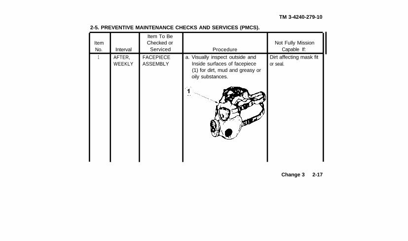
ItemNo.
1
Interval
AFTER,WEEKLY
Item To BeChecked or
Serviced
FACEPIECEASSEMBLY
Procedure
a. Visually inspect outside andInside surfaces of facepiece(1) for dirt, mud and greasy oroily substances.
Not Fully MissionCapable If:
Dirt affecting mask fitor seal.
Change 3 2-17
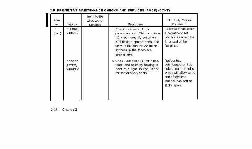
2-5. PREVENTIVE MAINTENANCE CHECKS AND SERVICES (PMCS) (CONT).
ItemNo.
1(cont)
2-18
BEFORE,AFTER,WEEKLY
Change 3
Interval
BEFORE,WEEKLY
Item To BeChecked or
Serviced Procedure
b. Check facepiece (1) forpermanent set. The facepiece(1) is permanently set when itis difficult to spread open, andthere is unusual or too muchstiffness in the facepiecesealing area.
c. Check facepiece (1) for holes,tears, and splits by holding infront of a light source Checkfor soft or sticky spots.
Not Fully MissionCapable If:
Facepiece has takena permanent set,which may affect thefit or seal of thefacepiece.
Rubber hasdeteriorated or hasholes, tears or splitswhich will allow air toenter facepiece.Rubber has soft orsticky spots.
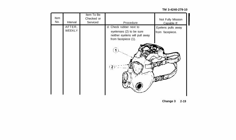
ItemNo. Interval
AFTER,WEEKLY
Item To BeChecked or
Serviced
TM 3-4240-279-10
Procedured. Check rubber next to
Not Fully MissionCapable If:
Eyelens pulls awayeyelenses (2) to be sure from facepiece.neither eyelens will pull awayfrom facepiece (1).
Change 3 2-19
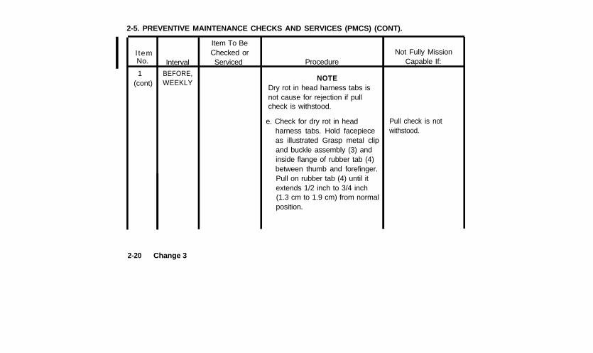
2-5. PREVENTIVE MAINTENANCE CHECKS AND SERVICES (PMCS) (CONT).
I temNo.
1(cont)
2-20
Interval
BEFORE,WEEKLY
Change 3
Item To BeChecked orServiced Procedure
NOTEDry rot in head harness tabs isnot cause for rejection if pullcheck is withstood.
e. Check for dry rot in headharness tabs. Hold facepieceas illustrated Grasp metal clipand buckle assembly (3) andinside flange of rubber tab (4)between thumb and forefinger.Pull on rubber tab (4) until itextends 1/2 inch to 3/4 inch(1.3 cm to 1.9 cm) from normalposition.
Pull check is notwithstood.
Not Fully MissionCapable If:
ItemNo. Interval
WEEKLY
Item To BeChecked or
Serviced
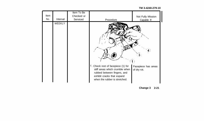
f .
TM 3-4240-279-10
ProcedureNot Fully Mission
Capable If:
Check rest of facepiece (1) forstiff areas which crumble whenrubbed between fingers, andexhibit cracks that expandwhen the rubber is stretched.
Facepiece has areasof dry rot.
Change 3 2-21
2-5. PREVENTIVE MAINTENANCE CHECKS AND SERVICES (PMCS) (CONT).
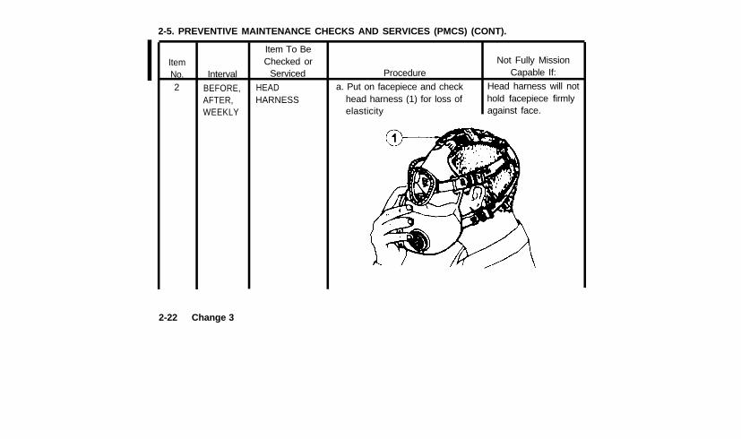
ItemNo.2
Interval
BEFORE,AFTER,WEEKLY
2-22 Change 3
Item To BeChecked or
Serviced
HEADHARNESS head harness (1) for loss of
Procedure
a. Put on facepiece and check
elasticity
Not Fully Mission
hold facepiece firmly
Capable If:
Head harness will not
against face.
TM 3-4240-279-10
ItemNo. Interval
AFTER,WEEKLY
Item To BeChecked or
Serviced Procedure
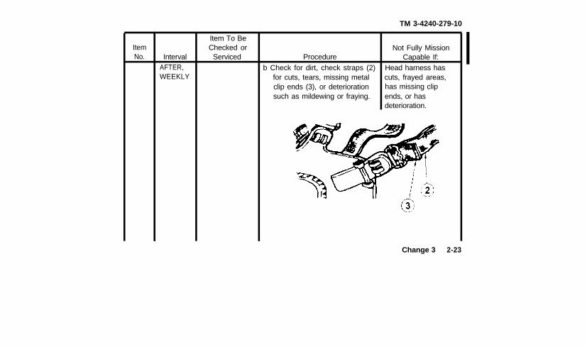
b Check for dirt, check straps (2)for cuts, tears, missing metalclip ends (3), or deteriorationsuch as mildewing or fraying.
Not Fully MissionCapable If:
Head harness hascuts, frayed areas,has missing clipends, or hasdeterioration.
Change 3 2-23
2-5. PREVENTIVE MAINTENANCE CHECKS AND SERVICES (PMCS) (CONT).
ItemNo
3
Interval
AFTER,WEEKLY
Item To BeChecked or
Serviced
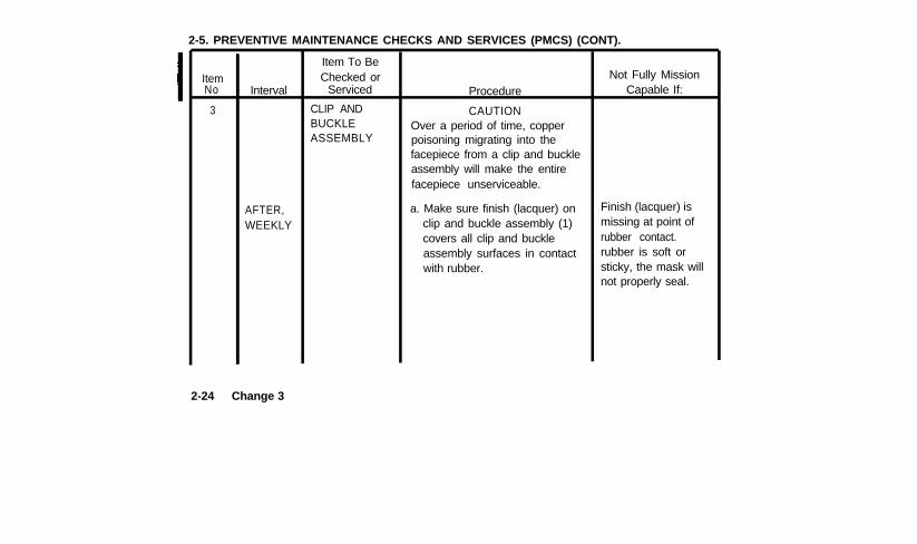
CLIP ANDBUCKLEASSEMBLY
Procedure
CAUTIONOver a period of time, copperpoisoning migrating into thefacepiece from a clip and buckleassembly will make the entirefacepiece unserviceable.
a. Make sure finish (lacquer) onclip and buckle assembly (1)covers all clip and buckleassembly surfaces in contactwith rubber.
Not Fully MissionCapable If:
Finish (lacquer) ismissing at point ofrubber contact.rubber is soft orsticky, the mask willnot properly seal.
2-24 Change 3
TM 3-4240-279-10
ItemNo.
4
IntervalBEFORE,AFTER,WEEKLY
AFTER,WEEKLY
Item To BeChecked or
Serviced
TEMPLE PINS
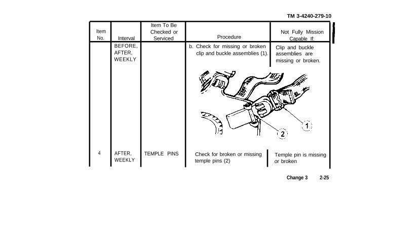
Not Fully MissionProcedure Capable If:
b. Check for missing or broken Clip and buckleclip and buckle assemblies (1). assemblies are
missing or broken.
Check for broken or missing Temple pin is missingtemple pins (2) or broken
Change 3 2-25
2-5. PREVENTIVE MAINTENANCE CHECKS AND SERVICES (PMCS) (CONT).
ItemNo
2-26
Interval
AFTER,WEEKLY
AFTER,WEEKLY
Change 3
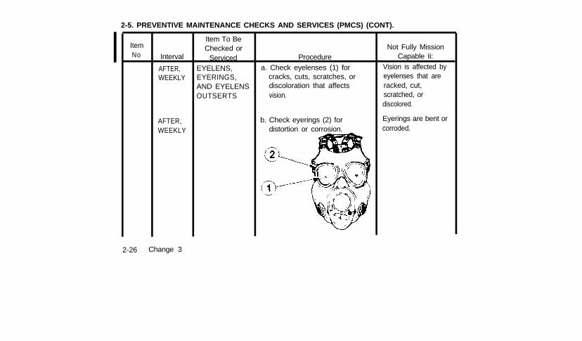
Item To BeChecked or
ServicedEYELENS,EYERINGS,AND EYELENSOUTSERTS
Procedurea. Check eyelenses (1) for
cracks, cuts, scratches, ordiscoloration that affectsvision.
b. Check eyerings (2) fordistortion or corrosion.
Not Fully MissionCapable Ii:
Vision is affected byeyelenses that areracked, cut,scratched, ordiscolored.
Eyerings are bent orcorroded.
TM 3-4240-279-10
ItemNo Interval
AFTER,WEEKLY
Item To BeChecked or
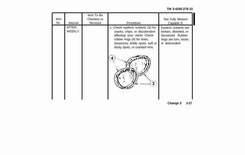
Serviced Procedurec. Check eyelens outserts (3) for
cracks, chips, or discolorationaffecting your vision Checkrubber rings (4) for tears,looseness, brittle spots, soft orsticky spots, or cracked rims.
Not Fully MissionCapable If:
Eyelens outserts arebroken, distorted, ordiscolored Rubberrings are torn, loose,or deteriorated.
Change 3 2-27
2-5. PREVENTIVE MAINTENANCE CHECKS AND SERVICES (PMCS) (CONT).
ItemNo.
6
2-28
Interval
BEFORE,AFTER,WEEKLY
Change 3
Item To BeChecked or
Serviced
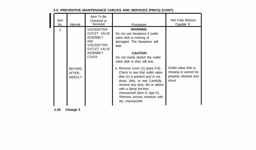
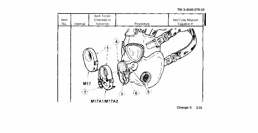
VOICEMITTER-OUTLET VALVEASSEMBLYANDVOICEMITTER-OUTLET VALVEASSEMBLYCOVER
Procedure
WARNINGDo not use facepiece if outletvalve disk is missing ordamaged. The facepiece willleak.
CAUTIONDo not overly stretch the outletvalve disk or they will tear.
a. Remove cover (1) (para 3-5).Check to see that outlet valvedisk (2) is present and is notdusty, dirty, or wet Carefullyremove any dust, dirt or debriswith a damp lint-freecheesecloth (item 5, App D).Remove excess moisture withdry cheesecloth.
Not Fully MissionCapable If:
Outlet valve disk ismissing or cannot beproperly cleaned anddried.
TM 3-4240-279-10
Procedure
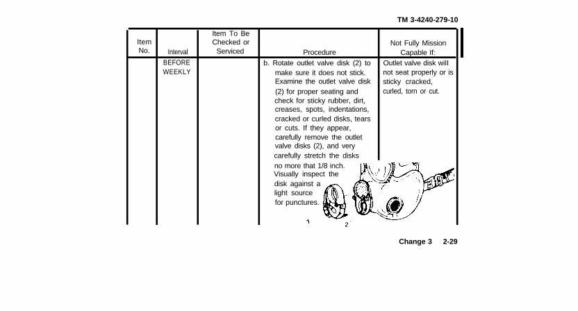
b. Rotate outlet valve disk (2) tomake sure it does not stick.Examine the outlet valve disk(2) for proper seating andcheck for sticky rubber, dirt,creases, spots, indentations,cracked or curled disks, tearsor cuts. If they appear,carefully remove the outletvalve disks (2), and verycarefully stretch the disks
Not Fully MissionCapable If:
Outlet valve disk wiIInot seat properly or issticky cracked,curled, torn or cut.
Item To BeItem Checked orNo. Interval Serviced
BEFOREWEEKLY
no more that 1/8 inch.Visually inspect thedisk against alight sourcefor punctures.
Change 3 2-29
2-5. PREVENTIVE MAINTENANCE CHECKS AND SERVICES (PMCS) (CONT).
ItemNo.
6(cont)
IntervalAFTER,WEEKLY
AFTER,WEEKLY
AFTER
AFTER
2-30 Change 3
Item To BeChecked or
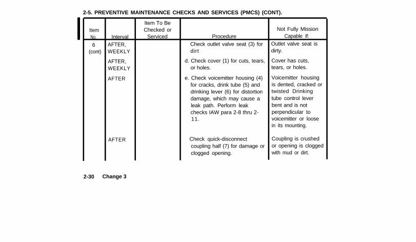
Serviced ProcedureCheck outlet valve seat (3) fordirt
d. Check cover (1) for cuts, tears,or holes.
e. Check voicemitter housing (4)for cracks, drink tube (5) anddrinking lever (6) for distortiondamage, which may cause aleak path. Perform leakchecks IAW para 2-8 thru 2-11.
Check quick-disconnectcoupling half (7) for damage orclogged opening.
Not Fully MissionCapable If:
Outlet valve seat isdirty.
Cover has cuts,tears, or holes.
Voicemitter housingis dented, cracked ortwisted Drinkingtube control leverbent and is notperpendicular tovoicemitter or loosein its mounting.
Coupling is crushedor opening is cloggedwith mud or dirt.
TM 3-4240-279-10
Change 3 2-31
2-5. PREVENTIVE MAINTENANCE CHECKS AND SERVICES (PMCS) (CONT).
ItemNo.
6(cont)
2-32
AFTER
Change 3
Interval
AFTER
Item To BeChecked or
Serviced Procedure
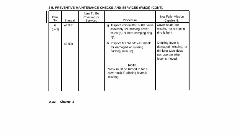
g. Inspect voicemitter outlet valveassembly for missing coverstuds (8) or bent crimping ring
(9).
h. Inspect M17A1/M17A2 maskfor damaged or missingdrinking lever (6).
NOTEMask must be turned in for anew mask if drinking lever ismissing.
Not Fully MissionCapable If:
Cover studs aremissing, or crimpingring is bent
Drinking lever isdamaged, missing, ordrinking tube doesnot operate whenlever is moved.
TM 3-4240-279-10
ItemNo. Interval
Item To BeChecked orServiced
Not Fully MissionProcedure Capable If:
AFTER,WEEKLY
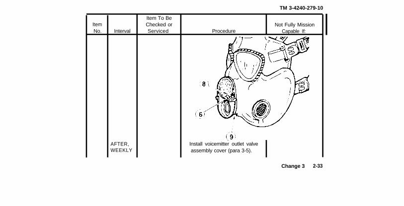
Install voicemitter outlet valveassembly cover (para 3-5).
Change 3 2-33
2-5. PREVENTIVE MAINTENANCE CHECKS AND SERVICES (PMCS) (CONT).
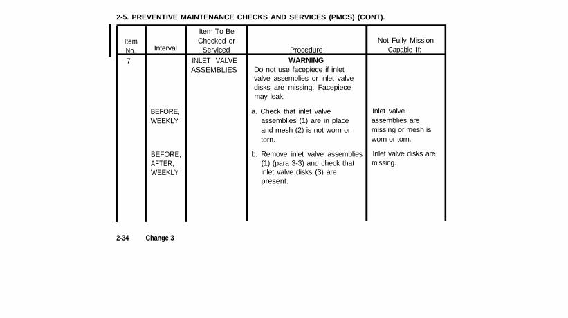
ItemNo.7
Interval
BEFORE,WEEKLY
BEFORE,AFTER,WEEKLY
Item To BeChecked or
Serviced
INLET VALVEASSEMBLIES
ProcedureWARNING
Do not use facepiece if inletvalve assemblies or inlet valvedisks are missing. Facepiecemay leak.
a. Check that inlet valve Inlet valveassemblies (1) are in place assemblies areand mesh (2) is not worn or missing or mesh istorn. worn or torn.
b. Remove inlet valve assemblies(1) (para 3-3) and check thatinlet valve disks (3) arepresent.
Inlet valve disks aremissing.
Not Fully MissionCapable If:
2-34 Change 3
TM 3-4240-279-10
ItemNo. Interval
BEFORE,AFTER,WEEKLY
Item To BeChecked or
Serviced Procedure
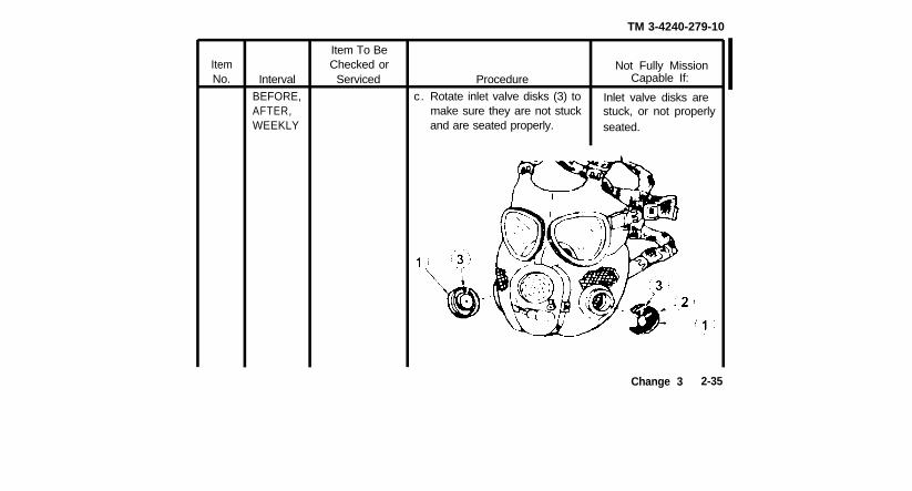
c. Rotate inlet valve disks (3) tomake sure they are not stuckand are seated properly.
Not Fully MissionCapable If:
Inlet valve disks arestuck, or not properlyseated.
Change 3 2-35
2-5. PREVENTIVE MAINTENANCE CHECKS AND SERVICES (PMCS) (CONT).
ItemNo.
7(cont)
2-36 Change 3
IntervalAFTER,WEEKLY
AFTER,WEEKLY
Item To BeChecked or
Serviced Procedure
d. Check for curled, discolored,or dirty inlet valve disks (3).
CAUTIONTo prevent damage, do not rollup inlet valve disks or they willtear.
Examine inlet valve disks (3)for dirt, creases, spots, orindentations If they appear,carefully remove inlet valvedisks (3). and very carefullystretch the disks no more than1/8 inch. Visually inspect thedisks against a light source forpunctures.
Not Fully MissionCapable If:
Inlet valve disks arecurled, discolored, ordirty.
Inlet valve disks arepunctured.
TM 3-4240-279-10
ItemNo. Interval
Item To BeChecked or
Serviced Procedure
NOTEThe word TOP may be missingor Incorrectly positioned. Exactlop may be marked with a whitedot See para 3-3 for removaland installation of inlet valveassemblies.
Not Fully MissionCapable If:
Change 3 2-36.1/(2.36.2 blank)
TM 3-4240-279-10
ItemNo Interval
BEFORE,AFTER,WEEKLY
Item To BeChecked or
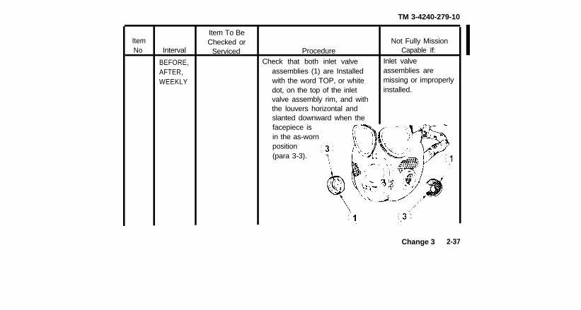
Serviced ProcedureCheck that both inlet valve
assemblies (1) are Installedwith the word TOP, or whitedot, on the top of the inletvalve assembly rim, and withthe louvers horizontal andslanted downward when the
Not Fully MissionCapable If:
Inlet valveassemblies aremissing or improperlyinstalled.
facepiece isin the as-wornposition(para 3-3).
Change 3 2-37
2-5. PREVENTIVE MAINTENANCE CHECKS AND SERVICES (PMCS) (CONT).
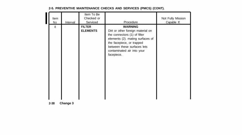
ItemNo
8
Interval
Item To BeChecked or
ServicedFILTERELEMENTS
Procedure
WARNINGDirt or other foreign material onthe connectors (1) of filterelements (2). mating surfaces ofthe facepiece, or trappedbetween these surfaces letscontaminated air into yourfacepiece.
Not Fully MissionCapable If:
2-38 Change 3
TM 3-4240-279-10
Not Fully MissionCapable If:
Filter elementconnectors are loose,or have dirtysurfaces.
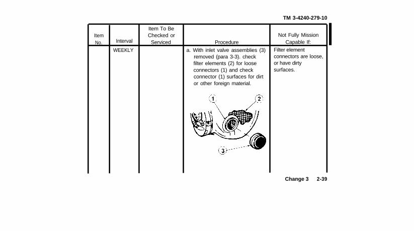
ItemNo. Interval
WEEKLY
Item To BeChecked or
Serviced Procedure
a. With inlet valve assemblies (3)removed (para 3-3). checkfilter elements (2) for looseconnectors (1) and checkconnector (1) surfaces for dirtor other foreign material.
Change 3 2-39
2-5. PREVENTIVE MAINTENANCE CHECKS AND SERVICES (PMCS) (CONT).
ItemNo
8(cont)
2-40
Interval
BEFOREWEEKLY
Change 3
Item To BeChecked or
Serviced Procedure
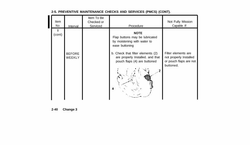
NOTEFlap buttons may be lubricatedby moistening with water toease buttoning
b. Check that filter elements (2)are properly Installed. and thatpouch flaps (4) are buttoned
Not Fully MissionCapable If:
Filter elements arenot properly Installedor pouch flaps are notbuttoned.
TM 3-4240-279-10
Item To BeItem Checked or Not Fully MissionNo. Interval Serviced Procedure Capable If:
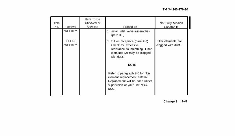
WEEKLY c. Install inlet valve assemblies(para 3-3).
BEFORE,WEEKLY
d. Put on facepiece (para 2-8). Filter elements areCheck for excessive clogged with dust.resistance to breathing. Filterelements (2) may be cloggedwith dust.
NOTE
Refer to paragraph 2-6 for filterelement replacement criteria.Replacement will be done undersupervision of your unit NBCNCO.
Change 3 2-41
2-5. PREVENTIVE MAINTENANCE CHECKS AND SERVICES (PMCS) (CONT).
ItemNo.
9
2-42
IntervalAFTER.WEEKLY
AFTER,WEEKLY
AFTERWEEKLY
Change 3
Item To BeChecked or
Serviced
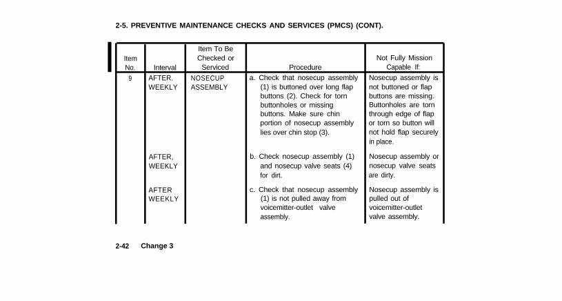
NOSECUPASSEMBLY
Procedurea. Check that nosecup assembly
(1) is buttoned over long flapbuttons (2). Check for tornbuttonholes or missingbuttons. Make sure chinportion of nosecup assemblylies over chin stop (3).
b. Check nosecup assembly (1)and nosecup valve seats (4)for dirt.
c. Check that nosecup assembly(1) is not pulled away fromvoicemitter-outlet valveassembly.
Not Fully MissionCapable If:
Nosecup assembly isnot buttoned or flapbuttons are missing.Buttonholes are tornthrough edge of flapor torn so button willnot hold flap securelyin place.
Nosecup assembly ornosecup valve seatsare dirty.
Nosecup assembly ispulled out ofvoicemitter-outletvalve assembly.
TM 3-4240-279-10
ItemNo. Interval
BEFORE,AFTER,WEEKLY
AFTER,WEEKLY
Item To BeChecked or
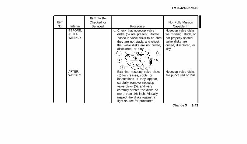
Serviced Procedured. Check that nosecup valve
disks (5) are present. Rotatenosecup valve disks to be surethey are not stuck, and checkthat valve disks are not curled,discolored. or dirty.
Examine nosecup valve disks(5) for creases, spots, orindentations. If they appear,carefully remove nosecupvalve disks (5), and verycarefully stretch the disks nomore than 1/8 inch. Visuallyinspect the disks against alight source for punctures.
Not Fully MissionCapable If:
Nosecup valve diskswe missing, stuck, ornot properly seated.valve disks arecurled, discolored, ordirty.
Nosecup valve disksare punctured or torn.
Change 3 2-43
2-5. PREVENTIVE MAINTENANCE CHECKS AND SERVICES (PMCS) (CONT)
ItemNo
Text
fabric.
2-44
IntervalAFTER,WEEKLY
AFTER,WEEKLY
AFTER,WEEKLY
Change 3
Item To BeChecked or
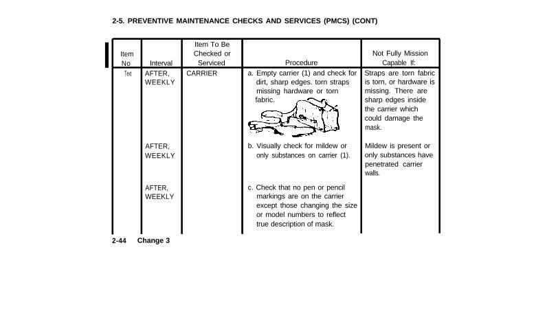
ServicedCARRIER
Procedurea. Empty carrier (1) and check for
dirt, sharp edges. torn strapsmissing hardware or torn
b. Visually check for mildew oronly substances on carrier (1).
c. Check that no pen or pencilmarkings are on the carrierexcept those changing the sizeor model numbers to reflecttrue description of mask.
Not Fully MissionCapable If:
Straps are torn fabricis torn, or hardware ismissing. There aresharp edges insidethe carrier whichcould damage themask.
Mildew is present oronly substances havepenetrated carrierwalls.

ItemNo.11
IntervalAFTER,WEEKLY
Item To BeChecked or
ServicedM 1WATERPROOFBAG
ProcedureCheck M1 waterproof bag (1)or M1A1* waterproof bag (2)for cracks, tears. holes. andbrittleness.
*May be authorized
TM 3-4240-279-10
Not Fully MissionCapable If:
Waterproof bag ismissing, torn, or hasholes.
Change 3 2-45
2-5. PREVENTIVE MAINTENANCE CHECKS AND SERVICES (PMCS) (CONT).
ItemNo.
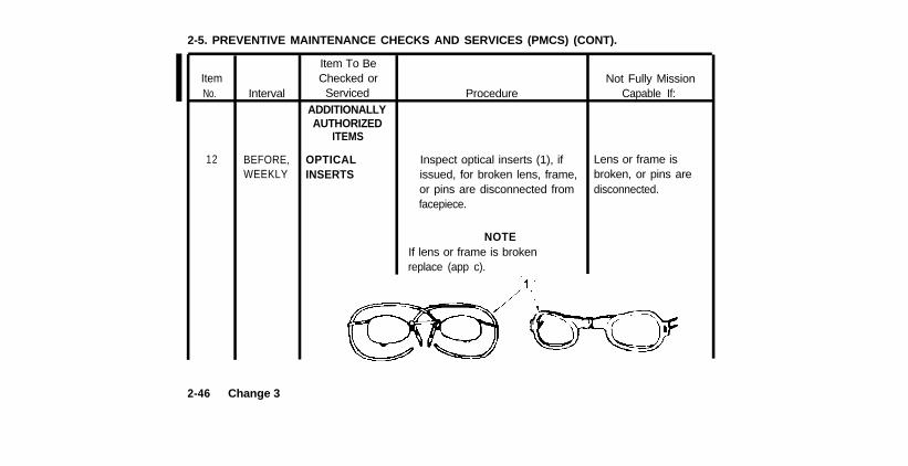
12
2-46
Interval
BEFORE,WEEKLY
Change 3
Item To BeChecked or
ServicedADDITIONALLYAUTHORIZED
ITEMS
OPTICALINSERTS
Procedure
Inspect optical inserts (1), ifissued, for broken lens, frame,or pins are disconnected fromfacepiece.
NOTEIf lens or frame is brokenreplace (app c).
Not Fully MissionCapable If:
Lens or frame isbroken, or pins aredisconnected.
TM 3-4240-279-10
ItemNo.
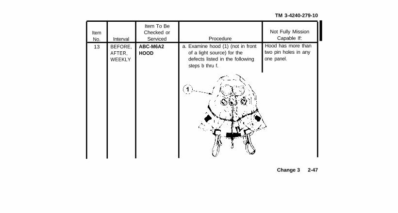
13
Interval
BEFORE,AFTER,WEEKLY
Item To BeChecked or
Serviced
ABC-M6A2HOOD
Procedure
a. Examine hood (1) (not in frontof a light source) for thedefects listed in the followingsteps b thru f.
Not Fully MissionCapable If:
Hood has more thantwo pin holes in anyone panel.
Change 3 2-47
2-5. PREVENTIVE MAINTENANCE CHECKS AND SERVICES (PMCS) (CONT).
ItemNo.
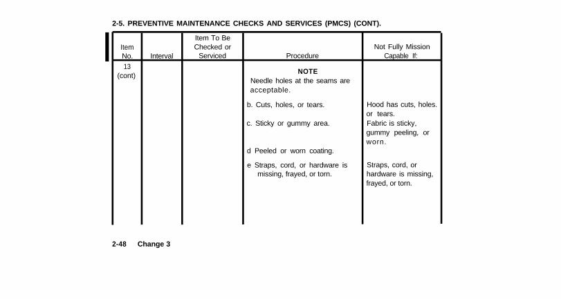
13(cont)
Interval
Item To BeChecked or
Serviced Procedure
NOTENeedle holes at the seams areacceptable.
b. Cuts, holes, or tears.
c. Sticky or gummy area.
d Peeled or worn coating.
e Straps, cord, or hardware ismissing, frayed, or torn.
Not Fully MissionCapable If:
Hood has cuts, holes.or tears.Fabric is sticky,gummy peeling, orworn.
Straps, cord, orhardware is missing,frayed, or torn.
2-48 Change 3
TM 3-4240-279-10
ItemNo. Interval
Item To BeChecked or
Serviced Procedure
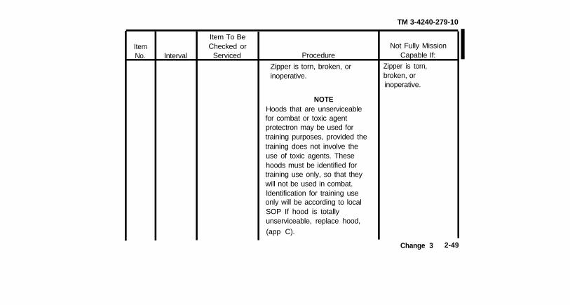
Zipper is torn, broken, orinoperative.
NOTEHoods that are unserviceablefor combat or toxic agentprotectron may be used fortraining purposes, provided thetraining does not involve theuse of toxic agents. Thesehoods must be identified fortraining use only, so that theywill not be used in combat.ldentification for training useonly will be according to localSOP If hood is totallyunserviceable, replace hood,
(app C).
Not Fully MissionCapable If:
Zipper is torn,broken, orinoperative.
Change 3 2-49
2-5. PREVENTIVE MAINTENANCE CHECKS AND SERVICES (PMCS) (CONT).
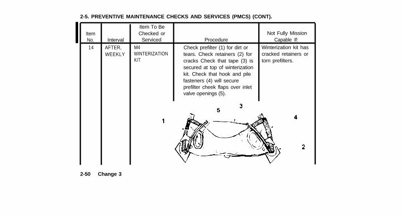
ItemNo.
14
Interval
AFTER,WEEKLY
Item To BeChecked or
Serviced
M4WINTERIZATIONKIT
Procedure
Check prefilter (1) for dirt ortears. Check retainers (2) forcracks Check that tape (3) issecured at top of winterizationkit. Check that hook and pilefasteners (4) will secureprefilter cheek flaps over inletvalve openings (5).
Not Fully MissionCapable If:
Winterization kit hascracked retainers ortorn prefilters.
2-50 Change 3
TM 3-4240-279-10
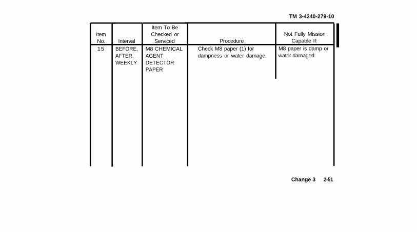
ItemNo.15
IntervalBEFORE,AFTER,WEEKLY
Item To BeChecked or
ServicedM8 CHEMICALAGENTDETECTORPAPER
ProcedureCheck M8 paper (1) fordampness or water damage.
Not Fully MissionCapable If:
M8 paper is damp orwater damaged.
Change 3 2-51
2-5. PREVENTIVE MAINTENANCE CHECKS AND SERVICES (PMCS) (CONT)
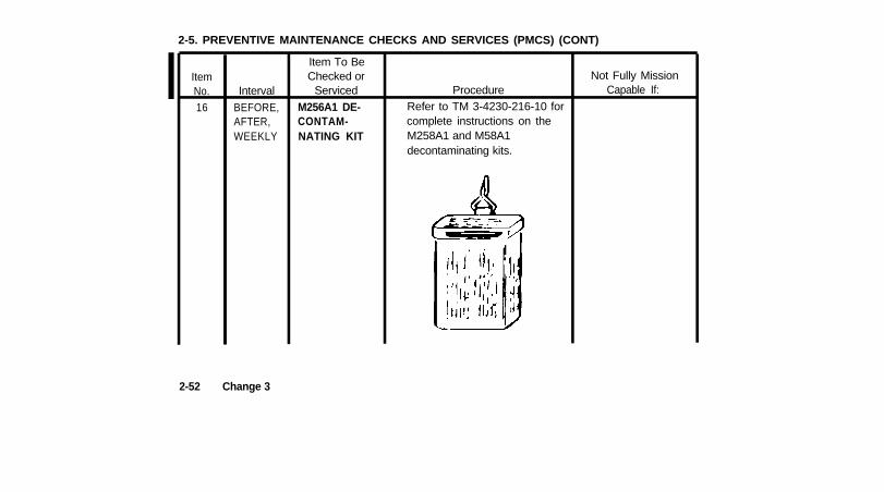
ItemNo.16
Interval
BEFORE,AFTER,WEEKLY
Item To BeChecked or
Serviced
M256A1 DE-CONTAM-NATING KIT
ProcedureRefer to TM 3-4230-216-10 forcomplete instructions on theM258A1 and M58A1decontaminating kits.
Not Fully MissionCapable If:
2-52 Change 3
TM 3-4240-279-10
ItemN o .
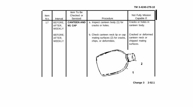
17
Interval
BEFORE,AFTER,WEEKLY
BEFORE,AFTER,WEEKLY
item To BeChecked or
Serviced
CANTEEN ANDM1 CAP
Procedure
a. Inspect canteen body (1) forcracks or holes.
b. Check canteen neck lip or capmating surfaces (2) for cracks,chips, or deformities.
Not Fully MissionCapable If:
Cracks or holes incanteen body.
Cracked or deformedcanteen neck orchipped matingsurfaces.
Change 3 2-52.1
2-5. PREVENTIVE MAINTENANCE CHECKS AND SERVICES (PMCS) (CONT).
ItemNo.
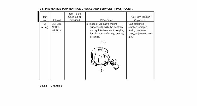
17(cont)
Interval
BEFOREAFTER,WEEKLY
Item To BeChecked or
Serviced
c. Inspect M1 cap’s matingsurfaces (3) with the canteenand quick-disconnect couplingfor dirt, rust deformity, cracks,or chips.
ProcedureNot Fully Mission
Capable If:
Cap deformedcracked, chippedmating surfaces,rusty, or jammed withdirt.
2-52.2 Change 3
TM 3-4240-279-10
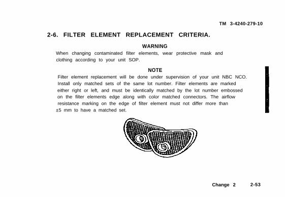
2-6. FILTER ELEMENT REPLACEMENT CRITERIA.
WARNINGWhen changing contaminated filter elements, wear protective mask andclothing according to your unit SOP.
NOTEFilter element replacement will be done under supervision of your unit NBC NCO.Install only matched sets of the same lot number. Filter elements are marked
either right or left, and must be identically matched by the lot number embossedon the filter elements edge along with color matched connectors. The airflowresistance marking on the edge of filter element must not differ more than
±5 mm to have a matched set.
Change 2 2-53
2-6. FILTER ELEMENT REPLACEMENT CRITERIA (CONT).
a. Combat zone, rapid deployment assignment (24 hours or less), and
special mission (e.g., explosive ordnance disposal, technical escort, chemical or nuclearaccident response teams, surety sites) units replace filter elements if one or more of thefollowing conditions exist:
(1) See table on following page for peacetime filter element replacement intervals,
by climate, for the above type units only.(2) Filter elements have been immersed in water.(3) Filter elements have splits or cuts in filter or edge seaI, or a bent or split
connector.(4) Filter elements have been crushed.
(5) You feel excessive resistance to breathing, and inspection shows that the filterelements are clogged.
(6) Unit maintenance informs you that the filter element has been reported as
unserviceable in SB 3-30-2.(7) Unit Commander directs replacement of filter elements.(8) Every 30 days after exposure to toxic agents and after each confirmed
attack with blood agents.
2-54 Change 1
TM 3-4240-279-10
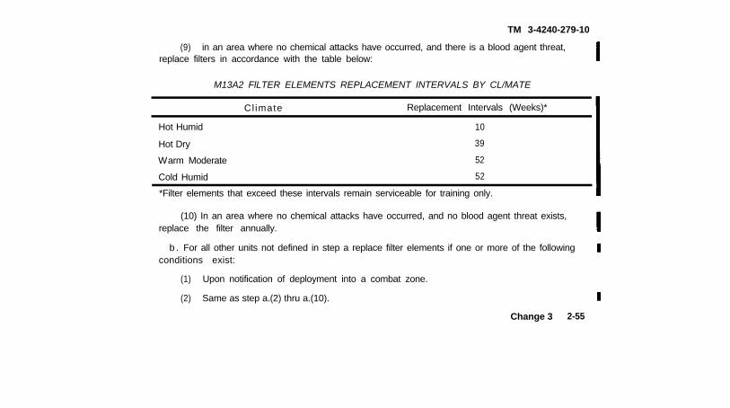
(9) in an area where no chemical attacks have occurred, and there is a blood agent threat,replace filters in accordance with the table below:
M13A2 FlLTER ELEMENTS REPLACEMENT INTERVALS BY CL/MATE
Cl imate Replacement Intervals (Weeks)*
Hot Humid
Hot Dry
Warm Moderate
10
39
52
Cold Humid 52
*Filter elements that exceed these intervals remain serviceable for training only.
(10) In an area where no chemical attacks have occurred, and no blood agent threat exists,replace the filter annually.
b . For all other units not defined in step a replace filter elements if one or more of the followingconditions exist:
(1) Upon notification of deployment into a combat zone.
(2) Same as step a.(2) thru a.(10).
Change 3 2-55
2-6. FILTER ELEMENT REPLACEMENT CRITERIA (CONT).
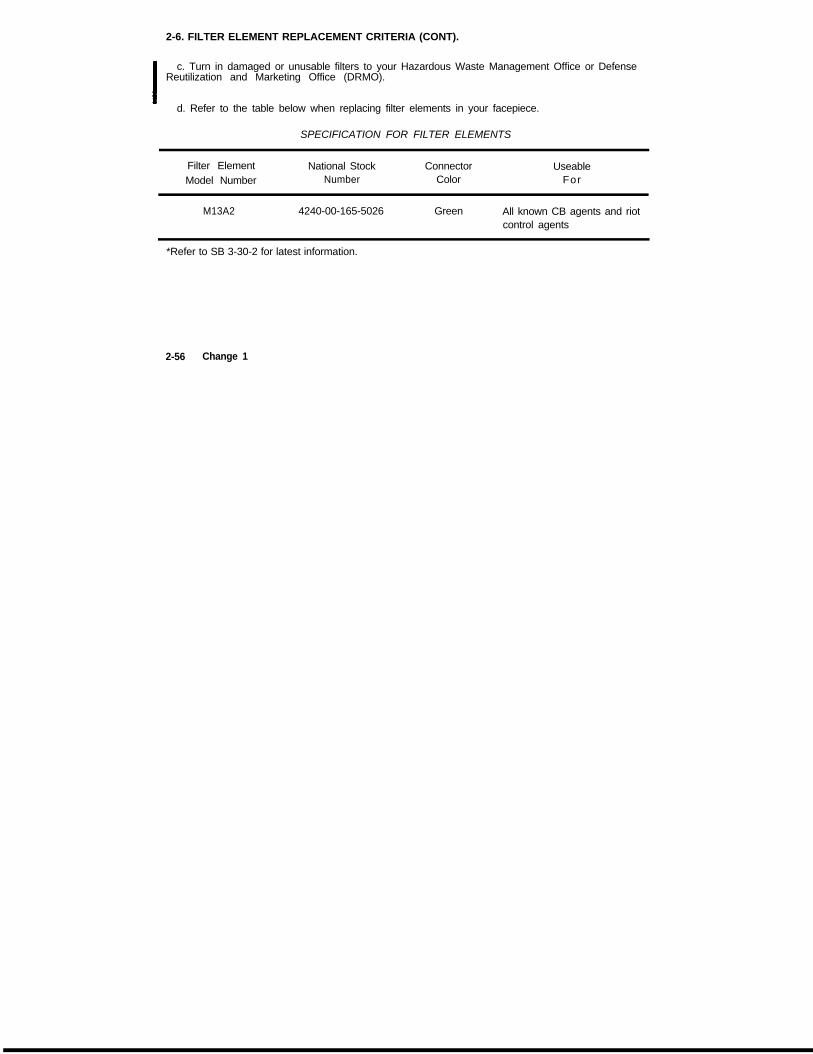
c. Turn in damaged or unusable filters to your Hazardous Waste Management Office or DefenseReutilization and Marketing Office (DRMO).
d. Refer to the table below when replacing filter elements in your facepiece.
SPECIFICATION FOR FILTER ELEMENTS
Filter Element National StockModel Number Number
ConnectorColor
UseableFor
M13A2 4240-00-165-5026 Green All known CB agents and riotcontrol agents
*Refer to SB 3-30-2 for latest information.
2-56 Change 1
Section III.
2-7. GENERAL.
TM 3-4240-279-10
OPERATION UNDER USUAL CONDITIONS
WARNINGDS2 can damage the voicemitter of the mask. If the voicemitter has been contaminatedwith DS2, immediately splash the voicemitter three times with clean water. Do not wetthe filter elements.
This section contains operator’s instructions to put on and use the mask and additionally autho-rized items under normal conditions. For operation under unusual conditions, see paragraphs
2-22 thru 2-26.
2-8. PUTTING ON YOUR FACEPIECE FOR FIT AND LEAK CHECK.NOTE
A trained unit NBC NCO will supervise size selection and initial fitting of your facepiece.However, it’s your responsibility to make sure your facepiece fits properly, has a good
seal, and is as comfortable as possible. Your NBC NCO has already
adjusted your forehead and temple straps at the initial fitting.
DO NOT change their adjustment. If adjustments become altered
see your NBC NCO.
a. Loosen cheek straps within 1 inch (2.5 cm) of metal clip ends.b. If you are wearing them, remove headgear and eyeglasses. Change 1 2-57
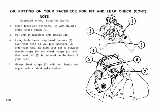
2-8. PUTTING ON YOUR FACEPIECE FOR FIT AND LEAK CHECK (CONT).
c.
d.
e.
f .
2-58
NOTEIllustrated without hood for clarity.
Open facepiece assembly (1) with thumbsunder cheek straps (2).
Put chin in facepiece chin pocket (3).
Using both hands, slip head harness (4)over your head as you pull facepiece uponto your face. Be sure your ear is betweentemple straps (5) and cheek straps (2), and
that head pad (6) is centered on the back ofyour head.
Grasp cheek straps (2) with both hands and
adjust with a short jerky motion.
TM 3-4240-279-10
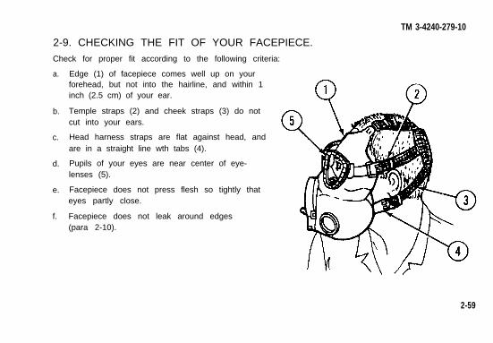
2-9. CHECKING THE FIT OF YOUR FACEPIECE.
Check for proper fit according to the following criteria:
a.
b.
c.
d.
e.
f.
Edge (1) of facepiece comes well up on yourforehead, but not into the hairline, and within 1inch (2.5 cm) of your ear.
Temple straps (2) and cheek straps (3) do notcut into your ears.
Head harness straps are flat against head, andare in a straight line wth tabs (4).
Pupils of your eyes are near center of eye-lenses (5).
Facepiece does not press flesh so tightly thateyes partly close.
Facepiece does not leak around edges(para 2-10).
2-59
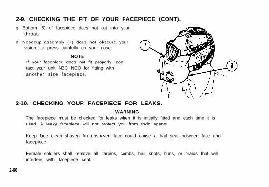
2-9. CHECKING THE FIT OF YOUR FACEPIECE (CONT).g. Bottom (6) of facepiece does not cut into your
throat.
h. Nosecup assembly (7) does not obscure yourvision, or press painfully on your nose.
NOTEIf your facepiece does not fit properly, con-tact your unit NBC NCO for fitting withanother s ize facepiece.
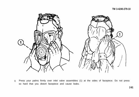
2-10. CHECKING YOUR FACEPIECE FOR LEAKS.WARNING
The facepiece must be checked for leaks when it is initially fitted and each time it isused. A leaky facepiece will not protect you from toxic agents.
Keep face clean shaven An unshaven face could cause a bad seal between face andfacepiece.
Female soldiers shall remove all harpins, combs, hair knots, buns, or braids that willinterfere with facepiece seal.
2-60
TM 3-4240-279-10
a. Press your palms firmly over inlet valve assemblies (1) at the sides of facepiece. Do not pressso hard that you distort facepiece and cause leaks.
2-61
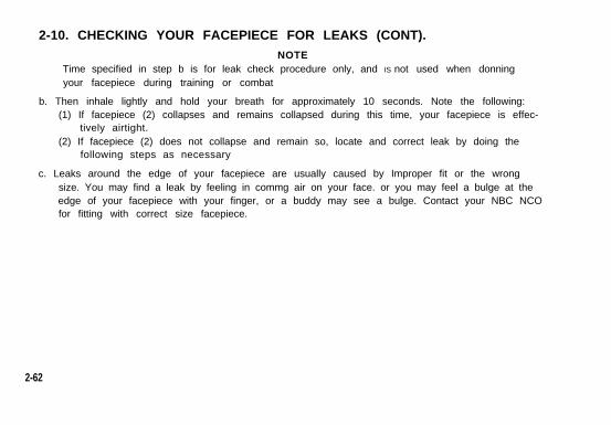
2-10. CHECKING YOUR FACEPIECE FOR LEAKS (CONT).NOTE
Time specified in step b is for leak check procedure only, and IS not used when donningyour facepiece during training or combat
b. Then inhale lightly and hold your breath for approximately 10 seconds. Note the following:(1) If facepiece (2) collapses and remains collapsed during this time, your facepiece is effec-
tively airtight.(2) If facepiece (2) does not collapse and remain so, locate and correct leak by doing the
following steps as necessary
c. Leaks around the edge of your facepiece are usually caused by Improper fit or the wrongsize. You may find a leak by feeling in commg air on your face. or you may feel a bulge at theedge of your facepiece with your finger, or a buddy may see a bulge. Contact your NBC NCOfor fitting with correct size facepiece.
2-62
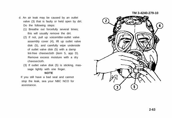
TM 3-4240-279-10d. An air Ieak may be caused by an outlet
valve (3) that is faulty or held open by dirt.Do the following steps:(1) Breathe out forcefully several times;
this will usually remove the dirt.(2) If not, pull up voicemitter-outlet valve
assembly cover (4), lift up outlet valve
disk (5), and carefully wipe undersideof outlet valve disk (5) with a damplint-free cheesecloth (item 5, app D).
Remove excess moisture with a drycheesecloth.
(3) If outlet valve disk (5) is sticking, mas-sage lightly with one finger.
NOTEIf you still have a bad seal and cannot
stop the leak, sea your NBC NCO forassistance.
2-63
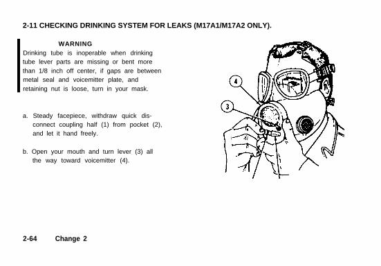
2-11 CHECKING DRINKING SYSTEM FOR LEAKS (M17A1/M17A2 ONLY).
WARNINGDrinking tube is inoperable when drinkingtube lever parts are missing or bent morethan 1/8 inch off center, if gaps are betweenmetal seal and voicemitter plate, andretaining nut is loose, turn in your mask.
a. Steady facepiece, withdraw quick dis-connect coupling half (1) from pocket (2),and let it hand freely.
b. Open your mouth and turn lever (3) allthe way toward voicemitter (4).
2-64 Change 2
TM 3-4240-279-10
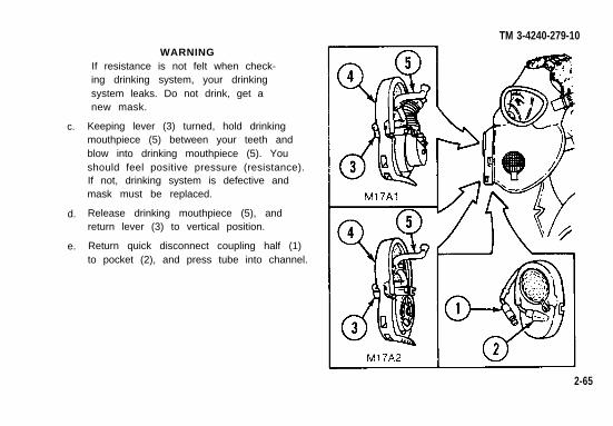
c.
d.
e.
WARNINGIf resistance is not felt when check-ing drinking system, your drinkingsystem leaks. Do not drink, get anew mask.
Keeping lever (3) turned, hold drinkingmouthpiece (5) between your teeth andblow into drinking mouthpiece (5). Youshould feel positive pressure (resistance).If not, drinking system is defective andmask must be replaced.
Release drinking mouthpiece (5), andreturn lever (3) to vertical position.
Return quick disconnect coupling half (1)to pocket (2), and press tube into channel.
2-65
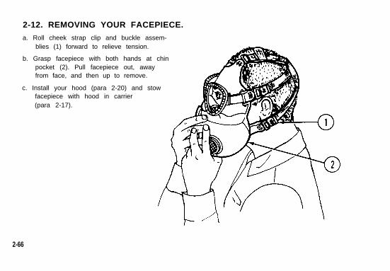
2-12. REMOVING YOUR FACEPIECE.a. Roll cheek strap clip and buckle assem-
blies (1) forward to relieve tension.
b. Grasp facepiece with both hands at chinpocket (2). Pull facepiece out, awayfrom face, and then up to remove.
c. Install your hood (para 2-20) and stowfacepiece with hood in carrier(para 2-17).
2-66
TM 3-4240-279-10
2-13. MARKING YOUR FACEPIECE FOR IDENTIFICATION.NOTE
Although a mask will be used only by the individual to whom it is issued and fitted, donot make permanent identification markings on either the facepiece or carrier(AR 700-84).
a. Under supervision of your unit NBC NCO, attach a removable tape or tag marked with yourname or a code number to your mask carrier.
b. The code number may include date the facepiece was fitted and tested. Code number mustnot identify parent organization or be similar to a neighboring unit.
2-14. PUTTING ON YOUR FACEPIECE, WITH HOOD, IN TRAINING ORCOMBAT.
WARNINGStop breathing when putting on your facepiece assembly. TOXIC agents maybe in thesurrounding air. Do the steps for putting on your facepiece quickly. The facepiece mustbe on before taking another breath. No one should be wearing contacts.
2-67
2-14. PUTTING ON YOUR FACEPIECE, WITH HOOD, IN TRAINING ORCOMBAT (CONT).
CAUTIONCare must be taken not to scratch the clear plastic eyelenses when handling the face-
a.
b.
c
d.
e.
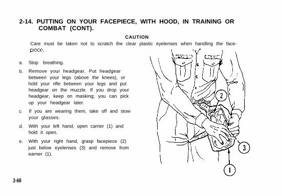
Stop breathing.
Remove your headgear. Put headgearbetween your legs (above the knees), orhold your rifle between your legs and putheadgear on the muzzle. If you drop yourheadgear, keep on masking; you can pickup your headgear later.
If you are wearing them, take off and stowyour glasses.
With your left hand, open carrier (1) andhold it open.
With your right hand, grasp facepiece (2)just below eyelenses (3) and remove fromearner (1).
2-68
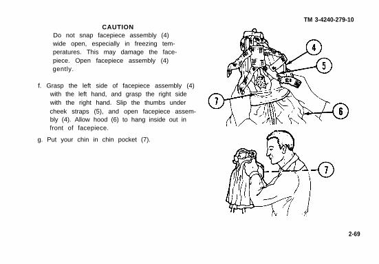
CAUTIONDo not snap facepiece assembly (4)wide open, especially in freezing tem-peratures. This may damage the face-piece. Open facepiece assembly (4)gently.
f. Grasp the left side of facepiece assembly (4)with the left hand, and grasp the right sidewith the right hand. Slip the thumbs undercheek straps (5), and open facepiece assem-bly (4). Allow hood (6) to hang inside out infront of facepiece.
g. Put your chin in chin pocket (7).
TM 3-4240-279-10
2-69
2-14. PUTTING ON YOUR FACEPIECE, WITH HOOD, IN TRAINING ORCOMBAT (CONT).
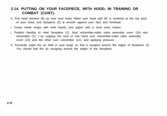
h. Pull head harness (8) up over your head, Make sure head pad (9) is centered at the top backof your head, and facepiece (2) is smooth against your face and forehead.
i. Grasp cheek straps with both hands, and adjust with a short jerky motion
j. Position hand(s) to clear facepiece (2). Seal voicemitter-outlet valve assembly cover (10) andvoicemitter (11 ) by cupping the heel of one hand over voicemitter-outlet valve assemblycover (10) and the other over voicemitter (11), and applying pressure.
k. Forcefully expel the air held in your lungs so that it escapes around the edges of facepiece (2)You should feel the air escaping around the edges of the facepiece.
2-70
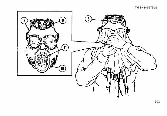
TM 3-4240-279-10
2-71
2-14. PUTTING ON YOUR FACEPIECE, WITH HOOD, IN TRAINING ORCOMBAT (CONT).
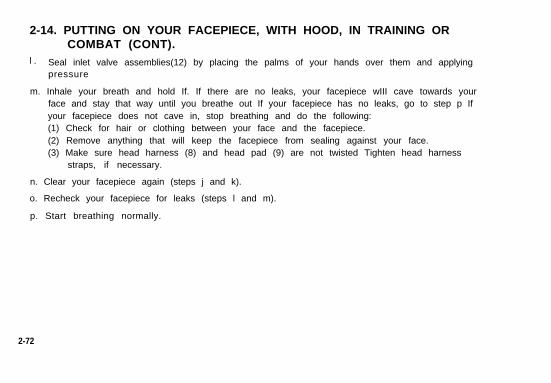
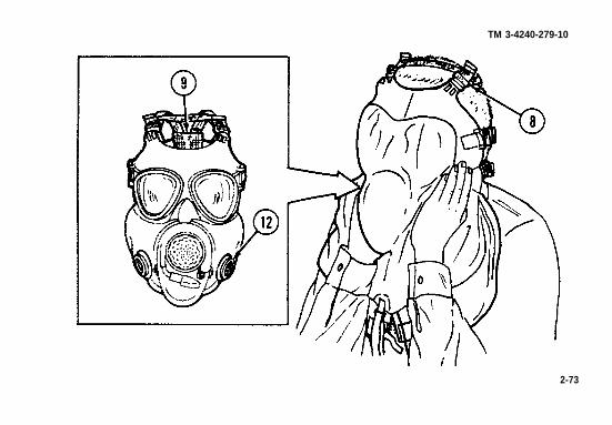
l . Seal inlet valve assemblies(12) by placing the palms of your hands over them and applyingpressure
m. Inhale your breath and hold If. If there are no leaks, your facepiece wIII cave towards yourface and stay that way until you breathe out If your facepiece has no leaks, go to step p Ifyour facepiece does not cave in, stop breathing and do the following:(1) Check for hair or clothing between your face and the facepiece.(2) Remove anything that will keep the facepiece from sealing against your face.(3) Make sure head harness (8) and head pad (9) are not twisted Tighten head harness
straps, if necessary.
n. Clear your facepiece again (steps j and k).
o. Recheck your facepiece for leaks (steps l and m).
p. Start breathing normally.
2-72
TM 3-4240-279-10
2-73
2-14. PUTTING ON YOUR FACEPIECE, WITH HOOD, IN TRAINING ORCOMBAT (CONT).
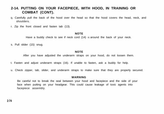
q. Carefully pull the back of the hood over the head so that the hood covers the head, neck, andshoulders.
r. Zip the front closed and fasten tab (13).
NOTEHave a buddy check to see if neck cord (14) IS around the back of your neck.
s. Pull slider (15) snug.
NOTEAfter you have adjusted the underarm straps on your hood, do not loosen them.
t. Fasten and adjust underarm straps (16). If unable to fasten, ask a buddy for help.
u. Check zipper, tab, slider, and underarm straps to make sure that they are properly secured.
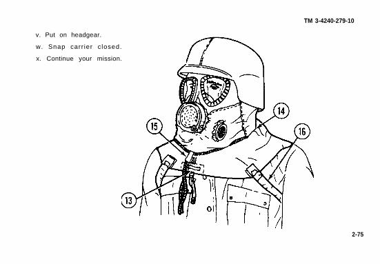
WARNINGBe careful not to break the seal between your hood and facepiece and the side of yourface when putting on your headgear. This could cause leakage of toxic agents intofacepiece assembly.
2-74
TM 3-4240-279-10
v. Put on headgear.
w. Snap carr ier c losed.
x. Continue your mission.
2-75
2-15. CONNECTING AND USING M17A1/M17A2 MASK DRINKINGSYSTEMS.
WARNINGDo not connect the quick disconnect coupling half to your canteen until all matingsurfaces and your chemical protective gloves have been checked for chemical contami-nation. Chemical agents can enter your mouth, resulting in sickness or death.
NOTETo use the M17A1/M17A2 mask drinking system, your canteen must be equipped withan M1 canteen cap.
a. FiII your plastic water canteen before entering contaminated area, or in a protective shelterwhen in a contaminated area.
b. Use M8 detector paper to check around pocket (1), canteen cap (2), and chemical protectivegloves set (3).
c. If contaminated, decontaminate using the M258A1 decontaminating kit.
2-76
TM 3-4240-279-10
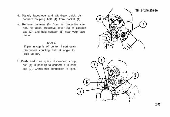
d. Steady facepiece and withdraw quick dis-connect coupling half (4) from pocket (1).
e. Remove canteen (5) from its protective car-rier, flip open protective cover (6) of canteencap (2), and hold canteen (5) near your face-piece.
NOTEIf pin in cap is off center, insert quickdisconnect coupling half at angle topick up pin.
f. Push and turn quick disconnect couphalf (4) in past lip to connect it to cantcap (2). Check that connection is tight.
2-77
2-15. CONNECTING AND USING M17A1/M17A2 MASK DRINKINGSYSTEMS (CONT).
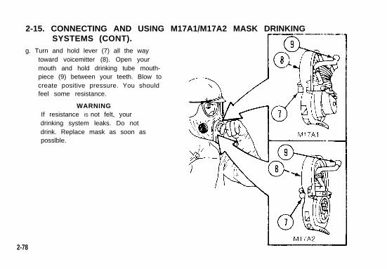
g. Turn and hold lever (7) all the waytoward voicemitter (8). Open yourmouth and hold drinking tube mouth-piece (9) between your teeth. Blow tocreate positive pressure. You shouldfeel some resistance.
WARNINGIf resistance IS not felt, yourdrinking system leaks. Do notdrink. Replace mask as soon asposslble.
2-78
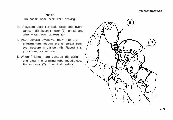
NOTEDo not tilt head back while drinking.
h. If system does not leak, raise and invertcanteen (5), keeping lever (7) turned, anddrink water from canteen (5).
i. After several swallows, blow into thedrinking tube mouthpiece to create posi-tive pressure in canteen (5). Repeat thisprocedure, as required.
j. When finished, turn canteen (5) uprightand blow into drinking tube mouthpiece.Return lever (7) to vertical position.
TM 3-4240-279-10
2-79
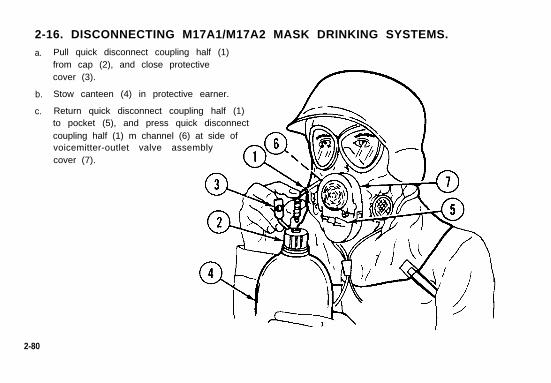
2-16. DISCONNECTING M17A1/M17A2 MASK DRINKING SYSTEMS.a.
b.
c.
Pull quick disconnect coupling half (1)from cap (2), and close protectivecover (3).
Stow canteen (4) in protective earner.
Return quick disconnect coupling half (1)to pocket (5), and press quick disconnectcoupling half (1) m channel (6) at side ofvoicemitter-outlet valve assemblycover (7).
2-80
TM 3-4240-279-10
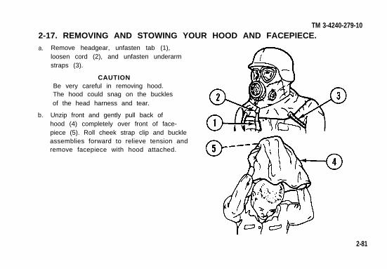
Remove headgear, unfasten tab (1),loosen cord (2), and unfasten underarmstraps (3).
CAUTIONBe very careful in removing hood.The hood could snag on the bucklesof the head harness and tear.
Unzip front and gently pull back ofhood (4) completely over front of face-piece (5). Roll cheek strap clip and buckleassemblies forward to relieve tension andremove facepiece with hood attached.
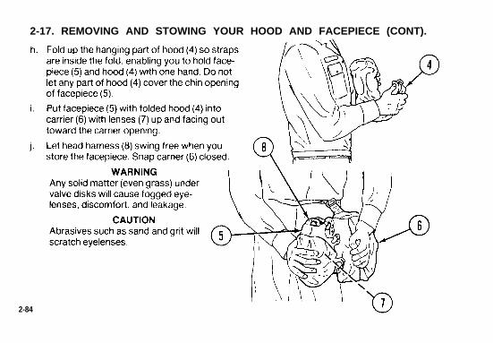
2-17. REMOVING AND STOWING YOUR HOOD AND FACEPIECE.a.
b.
2-81
2-17. REMOVING AND STOWING YOUR HOOD AND FACEPIECE (CONT).
c.
d.
e.
f.
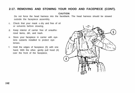
CAUTIONDo not force the head harness into the faceblank. The head harness should be stowedoutside the facepiece assembly.
Check that your mask IS dry and free of oilor solvents before stowing.
Keep interior of carrier free of unautho-rized items, dirt, and trash.
Store your facepiece in carrier with eye-Iens outserts installed to protect eye-Ienses.
Hold the edges of facepiece (5) with onehand. With the other, gently pull hood (4)over the front of the facepiece.
2-82
TM 3-4240-279-10
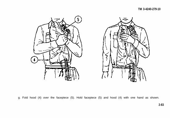
g. Fold hood (4) over the facepiece (5). Hold facepiece (5) and hood (4) with one hand as shown.
2-83
WARNING
CAUTION
2-17. REMOVING AND STOWING YOUR HOOD AND FACEPIECE (CONT).
2-84

TM 3-4240-279-10k. Store your facepiece in closed carrier (6) in a
cool, dark, dry place.
l. It is preferable to hang carrier (6) by shoulderstrap (9) or D-ring (10) on short strap on topof carrier.
m. Stow straps in one of two ways. Shoulderstrap (9) may be stowed in upper pocket (11),waist strap (12) in bottom pocket (13), orboth straps may be hooked to D-ring (10) bytheir snaphooks.
2-85
2-18. STOWING ITEMS IN CARRIER POCKETS.
CAUTIONTo avoid damage to facepiece, put only authorized items in your carrier.
a. Stow the M1 waterproof bag and the operator’s manual in inside pocket (1).
b. When stowing the M1A1 waterproof bag, when provided, roll up, slide into sleeve, bend in aU-shape, and stow in inside pocket (1).
c. If issued the following items, stow as follows:
2-86
TM 3-4240-279-10
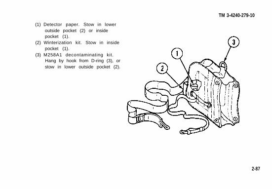
(1) Detector paper. Stow in loweroutside pocket (2) or insidepocket (1).
(2) Winterization kit. Stow in insidepocket (1).
(3) M258A1 decontaminating kit.Hang by hook from D-ring (3), orstow in lower outside pocket (2).
2-87
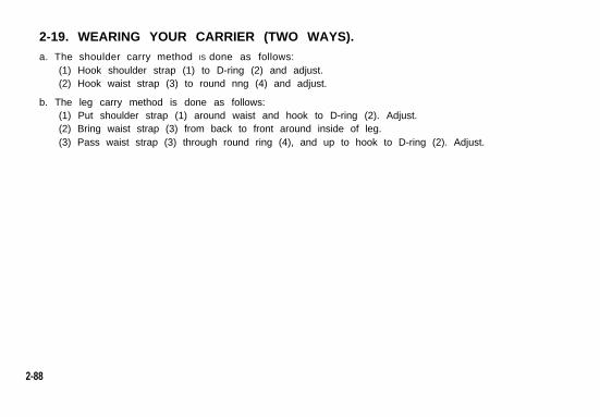
2-19. WEARING YOUR CARRIER (TWO WAYS).a. The shoulder carry method IS done as follows:
(1) Hook shoulder strap (1) to D-ring (2) and adjust.(2) Hook waist strap (3) to round nng (4) and adjust.
b. The leg carry method is done as follows:(1) Put shoulder strap (1) around waist and hook to D-ring (2). Adjust.(2) Bring waist strap (3) from back to front around inside of leg.(3) Pass waist strap (3) through round ring (4), and up to hook to D-ring (2). Adjust.
2-88
TM 3-4240-279-10
2-89
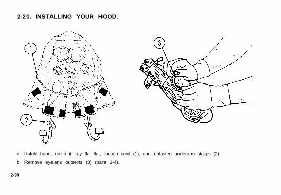
2-20. INSTALLING YOUR HOOD.
a. Unfold hood, unzip it, lay flat flat, loosen cord (1), and unfasten underarm straps (2).
b. Remove eyelens outserts (3) (para 3-4).
2-90
TM 3-4240-279-10
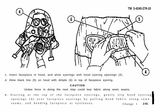
c. Insert facepiece in hood, and aline eyerings with hood eyering openings (4).
d. Aline black line (5) on hood with dimple (6) in top of facepiece eyering.
C A U T I O NUndue force in doing the next step could tear fabric along sewn seams.
e . S t a r t i n g a t t h e t o p o f t h e f a c e p i e c e e y e r i n g s , g e n t l y s l i p h o o d e y e r i n g
o p e n i n g s ( 4 ) o v e r f a c e p i e c e e y e r i n g s b y p u l l i n g h o o d f a b r i c a l o n g s e w n
s e a m s , a n d b e n d i n g f a c e p i e c e a t e y e l e n s e s . C h a n g e 1 2-91
2-20. INSTALLING YOUR HOOD (CONT).
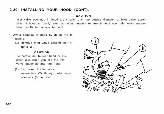
C A U T I O NInlet valve openings in hood are smaller than top outside diameter of inlet valve assem-
blies. If hood is “used,” even a modest attempt to stretch hood over inlet valve assem-blies results in damage to hood.
f. Avoid damage to hood by doing the fol-lowing:
(1) Remove inlet valve assemblies (7)
(para 3-3).
C A U T I O NBe careful not to tear hood or dis-place disk when you slip the inletvalve assembly into the hood.
(2) Slip base of inlet valve
assemblies (7) through inlet valve
openings (8) in hood.
2-92
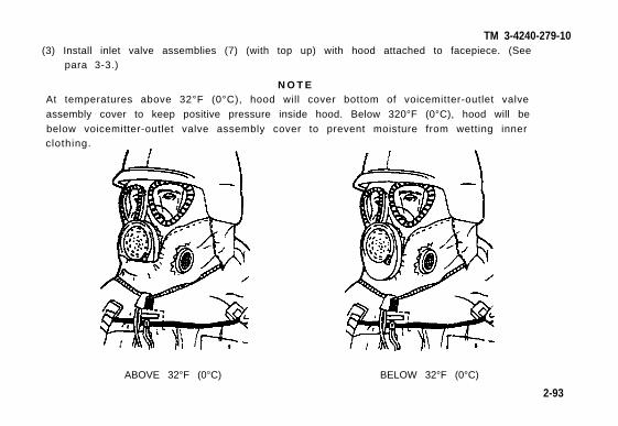
TM 3-4240-279-10(3) Install inlet valve assemblies (7) (with top up) with hood attached to facepiece. (See
para 3-3.)
N O T EAt temperatures above 32°F (0°C), hood will cover bottom of voicemitter-outlet valve
assembly cover to keep positive pressure inside hood. Below 320°F (0°C), hood will be
below voicemitter-outlet valve assembly cover to prevent moisture from wetting innerclothing.
ABOVE 32°F (0°C) BELOW 32°F (0°C)
2-93
2-20. INSTALLING YOUR HOOD (CONT).
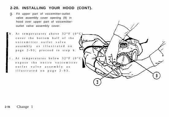
h .
i .
Fit upper part of voicemitter-outletvalve assembly cover opening (9) inhood over upper part of voicemitter-
outlet valve assembly cover.
A t t e m p e r a t u r e s a b o v e 3 2 ° F ( 0 ° C )
c o v e r t h e b o t t o m h a l f o f t h e
v o i c e m i t t e r o u t l e t v a l v e
a s s e m b l y a s i l l u s t r a t e d o n
p a g e 2 - 9 3 ; p r o c e e d t o s t e p k .
A t t e m p e r a t u r e s b e l o w 3 2 ° F ( 0 ° C )
e x p o s e t h e e n t i r e v o i c e m i t t e r
o u t l e t v a l v e a s s e m b l y a s
i l l u s t r a t e d o n p a g e 2 - 9 3 .
2-94 Change 1
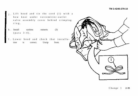
j .
k .
l .
TM 3-4240-279-10
L i f t h o o d a n d t i e t h e c o r d ( 1 ) w i t h a
b o w k n o t u n d e r v o i c e m i t t e r - o u t l e tv a l v e a s s e m b l y c o v e r b e h i n d c r i m p i n gr i n g .
Install eyelens outserts (3)
( p a r a 3 - 4 ) .
L o w e r h o o d a n d c h e c k t h a t i n s t a l l a -
tion is correct. Unzip front.
C h a n g e 1 2-95
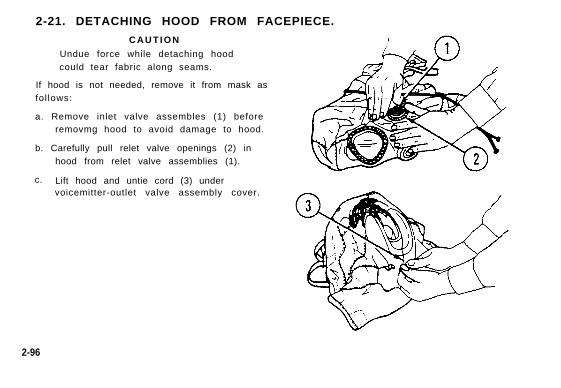
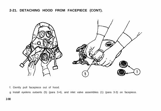
2-21. DETACHING HOOD FROM FACEPIECE.
C A U T I O N
Undue force while detaching hoodcould tear fabric along seams.
If hood is not needed, remove it from mask asfol lows:
a. Remove inlet valve assembles (1) beforeremovmg hood to avoid damage to hood.
b. Carefully pull relet valve openings (2) inhood from relet valve assemblies (1).
c. Lift hood and untie cord (3) undervoicemitter-outlet valve assembly cover.
2-96
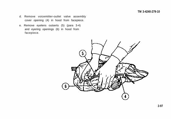
TM 3-4240-279-10d. Remove voicemitter-outlet valve assembly
cover opening (4) in hood from facepiece.
e. Remove eyelens outserts (5) (para 3-4)and eyering openings (6) in hood fromfacepiece.
2-97
2-21. DETACHING HOOD FROM FACEPIECE (CONT).
f. Gently pull facepiece out of hood.
g Install eyelens outserts (5) (para 3-4), and inlet valve assemblies (1) (para 3-3) on facepiece.
2-98
TM 3-4240-279-10
Section IV. OPERATION UNDER UNUSUAL CONDITIONS
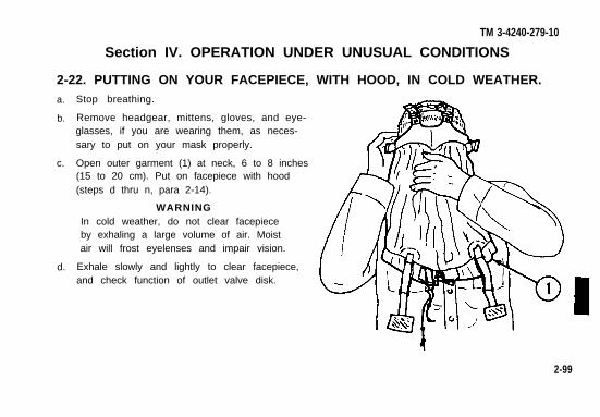
2-22. PUTTING ON YOUR FACEPIECE, WITH HOOD, IN COLD WEATHER.a.
b.
c.
d.
Stop breathing.
Remove headgear, mittens, gloves, and eye-glasses, if you are wearing them, as neces-sary to put on your mask properly.
Open outer garment (1) at neck, 6 to 8 inches(15 to 20 cm). Put on facepiece with hood(steps d thru n, para 2-14).
WARNINGIn cold weather, do not clear facepieceby exhaling a large volume of air. Moistair will frost eyelenses and impair vision.
Exhale slowly and lightly to clear facepiece,and check function of outlet valve disk.
2-99
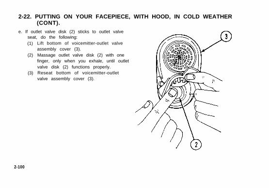
2-22. PUTTING ON YOUR FACEPIECE, WITH HOOD, IN COLD WEATHER(CONT).
e. If outlet valve disk (2) sticks to outlet valveseat, do the following:(1)
(2)
(3)
Lift bottom of voicemitter-outlet valveassembly cover (3).Massage outlet valve disk (2) with onefinger, only when you exhale, until outletvalve disk (2) functions properly.Reseat bottom of voicemitter-outletvalve assembly cover (3).
2-100
TM 3-4240-279-10
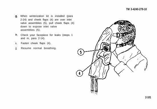
When winterization kit is installed (para2-24) and cheek flaps (4) are over inletvalve assemblies (5), pull cheek flaps (4)down to expose inlet valveassemblies (5).
Check your facepiece for leaks (steps 1and m, para 2-14).
Fasten cheek flaps (4).
Resume normal breathing.
2-101
l .
2-22. PUTTING ON YOUR FACEPIECE, WITH HOOD, IN COLD WEATHER(CONT).
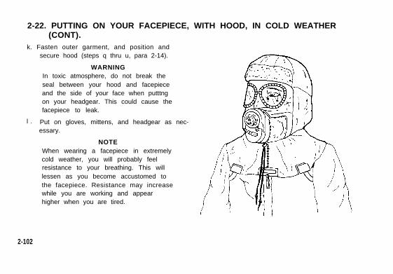
k. Fasten outer garment, and position andsecure hood (steps q thru u, para 2-14).
WARNINGIn toxic atmosphere, do not break theseal between your hood and facepieceand the side of your face when putttngon your headgear. This could cause thefacepiece to leak.
Put on gloves, mittens, and headgear as nec-essary.
NOTEWhen wearing a facepiece in extremelycold weather, you will probably feelresistance to your breathing. This willlessen as you become accustomed tothe facepiece. Resistance may increasewhile you are working and appearhigher when you are tired.
2-102
TM 3-4240-279-10
2-23. REMOVING YOUR FACEPIECE WITH HOOD IN COLD WEATHER.WARNING
If you become overheated in extremely cold weather, do not remove your facepieceoutdoors until your face and head have cooled and any sweat has dried. Frostbite, orother cold weather injury, may result if the facepiece is removed and the face is not driedimmediately.
a. Remove mittens and gloves as necessary.
b. Remove headgear, hood, and facepiece (steps a and b, para 2-17).
c. Shake ice accumulation from face piece.
d. Stow facepiece in carrier and snap carrier closed (steps c thru m, para 2-17).
e. Put on headgear and fasten outer garment.
f. Put on gloves and mittens.
2-103
2-24. INSTALLING YOUR WINTERIZATION KIT ON FACEPIECE WITH
a.
b.
c.
d.
HOOD.CAUTION
The fit of the winterization kit when used with the M6A2 hood is rather tight. Extra caremust be taken during installation to avoid tearing the hood.
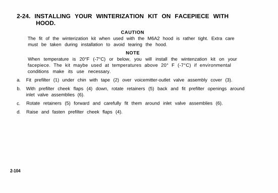
NOTEWhen temperature is 20°F (-7°C) or below, you will install the wintenzation kit on yourfacepiece. The kit maybe used at temperatures above 20° F (-7°C) if environmentalconditions make its use necessary.
Fit prefilter (1) under chin with tape (2) over voicemitter-outlet valve assembly cover (3).
With prefilter cheek flaps (4) down, rotate retainers (5) back and fit prefilter openings aroundinlet valve assemblies (6).
Rotate retainers (5) forward and carefully fit them around inlet valve assemblies (6).
Raise and fasten prefilter cheek flaps (4).
2-104
TM 3-4240-279-10
2-105
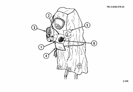
2-25. REMOVING YOUR WINTERIZATION KIT.a.
b.
c.
d.
e.
Unfasten prefilter cheek flaps (1).
Rotate retainers (2) off of inlet valve assem-blies (3).
Remove prefilter openings from around inletvalve assembles (3) to release prefilter (4).
Remove tape (5) from over voicemitter-outletvalve assembly cover (6).
Fold winterization kit into thirds and stow ininside pocket of carrier.
2-106
TM 3-4240-279-10
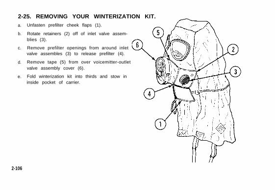
2-26. CARING FOR YOUR MASK IN COLD WEATHER.a.
b.
c.
Check for proper installation of hood (1)(para 2-20), eyelens outserts (2) (para 3-4),and winterization kit (3) (para 2-24).
When winterization kit (3) is installed, face-piece can be stored in carrier with prefiltercheek flaps (4) over inlet valve assembles (5).
Between repeated uses, remove your face-piece from carrier and carefully flex face-piece.
2-107
2-26. CARING FOR YOUR MASK IN COLD WEATHER (CONT).
d.
e.
f.
g.
h.
2-108
CHAPTER 3 TM 3-4240-279-10
MAINTENANCE INSTRUCTIONS
Section I. LUBRICATION INSTRUCTIONS
No lubrication is required for the M17 and M17A1/M17A2 masks.
Section II. MAINTENANCE PROCEDURES
3-1. GENERAL.
a. This section contains step-by-step procedures for maintaining the mask and additionallyauthorized items.
b. You, the operator, are authorized to inspect and service the mask and additionally
authorizd items. It is your responsibility to notify your NCO or officer of all defects and ofmaintenance part requirements not authorized in this manual.
3-1
3-2. FILTER ELEMENTS - SERVICING.
WARNING
Dirt or other foreign material on the connectors of filter elements, mating surfaces of thefaceblank, or trapped between these surfaces lets contaminated air into your facepiece.
Replacement of filter elements, when required, will be accomplished under direction of
your unit NBC NCO.
3-2 Change 1
TM 3-4240-279-10
3-3. INLET VALVE ASSEMBLIES - REMOVAL AND INSTALLATION.a. Removal.
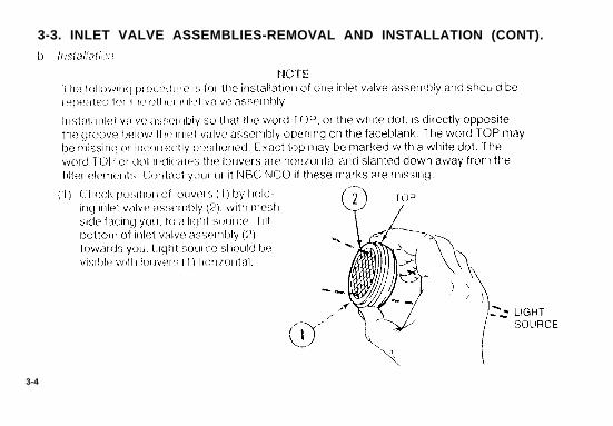
NOTEThe following procedure is for theremoval of one inlet valve assemblyand should be repeated for the otherinlet valve assembly.
Remove inlet valve assembly (1) from thefacepiece by pushing up on bottom edge ofinlet valve assembly with thumbs.
3-3
3-3. INLET VALVE ASSEMBLIES-REMOVAL AND INSTALLATION (CONT).
3-4
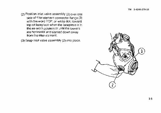
(2) Position inlet valve assembly (2)overone
sick of filter element connector flange (3)
with the word TOP, or white M., toward
top d facepiece when the facepiece is in
the as-worn Wsition or W-ltil the louvers
are hotizonta! and slanted down away
from the filter element.
(3) Snap inlet valve assembly (2) into place.
TM 3-4240-279-10
3-5
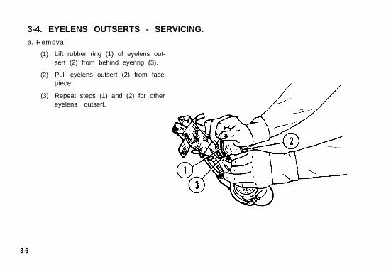
3-4. EYELENS OUTSERTS - SERVICING.a. Removal.
(1)
(2)
(3)
Lift rubber ring (1) of eyelens out-sert (2) from behind eyenng (3).
Pull eyelens outsert (2) from face-piece.
Repeat steps (1) and (2) for othereyelens outsert.
3-6
TM 3-4240-279-10
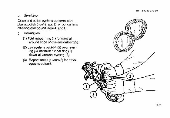
b. Sewicing
C3ean and polish eyekms cwtserts with
plastic polish (item 8, app D) or optical lens
cleaning com~und @svTl 4, app D).
c. /nsta!lation
(1) Fold rubber ring (1) forward all
around edge of eyekns cwtsert (2).
(~) Lay eyeknS OUtSWt (2] C)VW (S+K?~-
ing (3), and turn rubber ring(1)
(3)
d6wn all around eyering (~. ”
Re~at steps(1) and (2) for other
eyeiens cwtsert.
3-7
3-5. MASK - SERVICING.a. Decon ta rma t i on .
WARNINGDS2 can damage the voicemitter of the mask. If the voicemitter has been contaminatedwith DS2, immediately splash the voicemitter three times with clean water. Do not wetthe falter elements.
Use the M258A1 skin decontaminating kit to minimize the dangers of agents which may get intoyour facepiece while you are wearing it. Instructions for use are in TM3-4230-216-10.
b. Clean ing.
NOTEWhen you clean your mask, use only potable water. See your NCO or officer forsupplies or assistance if needed.
Winterization kit, hood, and eyelens inserts must be removed, if installed.
3-8
TM 3-4240-279-10
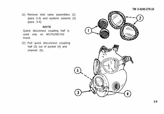
(1) Remove inlet valve assemblies (1)(para 3-3) and eyelens outserts (2)(para 3-4).
NOTEQuiick disconnect coupling half isused only on M17A1/M17A2mask.
(2) Pull quick disconnect couplinghalf (3) out of pocket (4) andchannel (5).
3-9
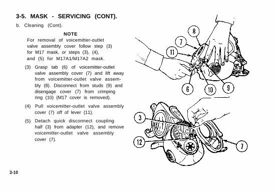
3-5. MASK - SERVICING (CONT).b. Cleaning (Cont).
NOTEFor removal of voicemitter-outletvalve assembly cover follow step (3)for M17 mask, or steps (3), (4),and (5) for M17A1/M17A2 mask.
(3)
(4)
(5)
Grasp tab (6) of voicemitter-outletvalve assembly cover (7) and lift awayfrom voicemitter-outlet valve assem-bly (8). Disconnect from studs (9) anddisengage cover (7) from crimpingring (10) (M17 cover is removed).
Pull voicemitter-outlet valve assemblycover (7) off of lever (11).
Detach quick disconnect couplinghalf (3) from adapter (12), and removevoicemitter-outlet valve assemblycover (7).
3-10
TM 3-4240-279-10
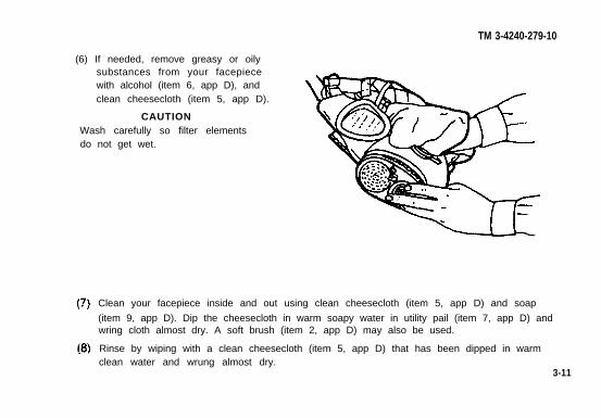
(6) If needed, remove greasy or oilysubstances from your facepiecewith alcohol (item 6, app D), andclean cheesecloth (item 5, app D).
CAUTIONWash carefully so filter elementsdo not get wet.
Clean your facepiece inside and out using clean cheesecloth (item 5, app D) and soap
(item 9, app D). Dip the cheesecloth in warm soapy water in utility pail (item 7, app D) andwring cloth almost dry. A soft brush (item 2, app D) may also be used.
Rinse by wiping with a clean cheesecloth (item 5, app D) that has been dipped in warmclean water and wrung almost dry.
3-11
3-5. MASK - SERVICING (CONT).
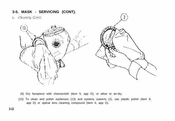
(9) Dry facepiece with cheesecloth (item 5, app D), or allow to air-dry.
(10) To clean and polish eyelenses (13) and eyelens outserts (2), use plastlc polish (item 8,app D) or optical lens cleaning compound (item 4, app D).
3-12
TM 3-4240-279-10
CAUTION
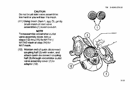
Do not brush inlet valve assemblies
tm hard or you will tear the mesh.
(11 ] using ImJsh (item 1, app D), Cymtly
brush mesh d inlet valve
aswmbnes (1 ] to remove cm
NOTE
To reaswm~e voiwmitterautlet
valve aswmbly cover, Wow
steps (12) thru (15] for M17A1/
Ml 7A2 mask or step(14] for
M17 mask
3-13
3-5. MASK - SERVICING (CONT).b. Cleaning (Cont).
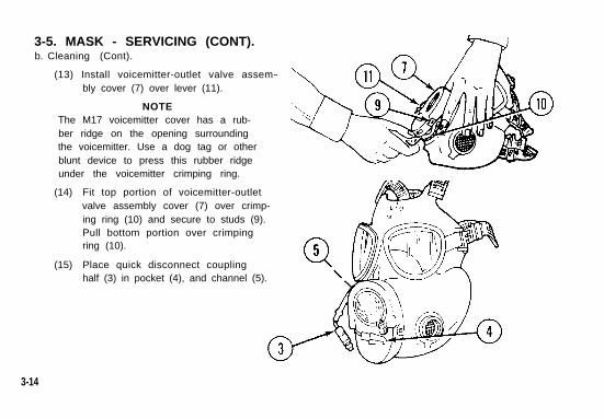
(13) Install voicemitter-outlet valve assem-bly cover (7) over lever (11).
NOTEThe M17 voicemitter cover has a rub-ber ridge on the opening surroundingthe voicemitter. Use a dog tag or otherblunt device to press this rubber ridgeunder the voicemitter crimping ring.
(14)
(15)
Fit top portion of voicemitter-outletvalve assembly cover (7) over crimp-ing ring (10) and secure to studs (9).Pull bottom portion over crimpingring (10).
Place quick disconnect couplinghalf (3) in pocket (4), and channel (5).
3-14
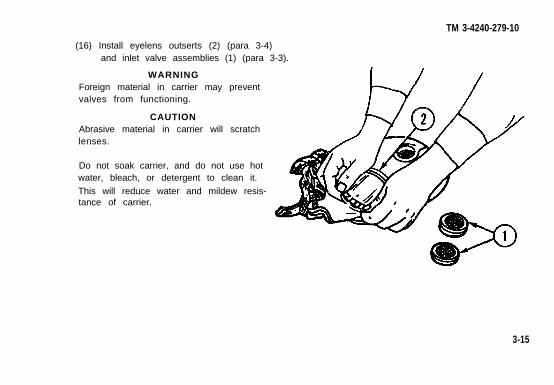
(16) Install eyelens outserts (2) (para 3-4)and inlet valve assemblies (1) (para 3-3).
WARNINGForeign material in carrier may preventvalves from functioning.
CAUTIONAbrasive material in carrier will scratchlenses.
Do not soak carrier, and do not use hotwater, bleach, or detergent to clean it.
This will reduce water and mildew resis-tance of carrier.
TM 3-4240-279-10
3-15
3-5. MASK - SERVICING (CONT).b. Cleaning (Cont).
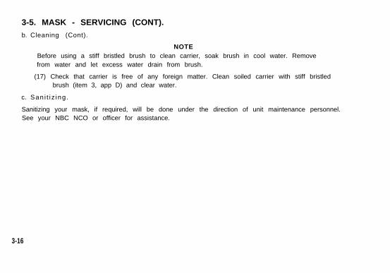
NOTEBefore using a stiff bristled brush to clean carrier, soak brush in cool water. Removefrom water and let excess water drain from brush.
(17) Check that carrier is free of any foreign matter. Clean soiled carrier with stiff bristledbrush (item 3, app D) and clear water.
c. Sani t i z ing .
Sanitizing your mask, if required, will be done under the direction of unit maintenance personnel.See your NBC NCO or officer for assistance.
3-16

TM 3-4240-279-10
APPENDIX AREFERENCES
A-1 . SCOPE.This apppendix lists all forms, technical manuals, and miscellaneous publications referenced in thismanual.
A-2. FORMS.DA Form 2028 . . . . . . . . . . . . . Recommended Changes to Publications and Blank FormsDA Form 2404 . . . . . . . . . . . . . Equipment Inspection and Maintenance WorksheetSF 368 . . . . . . . . . . . . . . . . . . .Product Quality Deficiency Report
A-3. FIELD MANUALS.FM21-11 . . . . . . . . . . . . . . . . . First Aid for Soldiers
A-1
A-4. TECHNICAL MANUALS.TM 3-4230-216-10 . . . . . . . Decontaminating Kit, Skin, M258A1
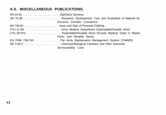
A-5. MISCELLANEOUS PUBLICATIONS.AR 40-63. . . . . . . . . . . . . . . . . .. . . . . . . .Opthalmic ServicesAR 70-38 . . . . . . . . . . . . . . . . . .Research, Development, Test, and Evaluation of Materiel for
Extreme Climatic ConditionsAR 700-84 . . . . .. . . . . . . . . . . . . . . . Issue and Sale of Personal ClothingCTA 8-100 . . . . . . . . . . . . . . . . Army Medical Department Expendable/Durable ItemsCTA 50-970 . . . . . . . . . . . . . . . . . .Expendable/Durable Items (Except: Medical, Class V, Repair
Parts, and Heraldic Items)DA PAM 738-750 . . . . . . . . . . .The Army Maintenance Management System (TAMMS)SB 3-30-2 . . . . . . . . . . . . . . . . . . . Chemical-Biological Canisters and Filter Elements:
Serviceability Lists
A-2
TM 3-4240-279-10
APPENDIX BCOMPONENTS OF END ITEM AND BASIC ISSUE ITEMS LIST
Section I. INTRODUCTION
B-1. SCOPE.This appendix lists components of end item and basic issue items for the M17/M17A1/M17A2masks to help you inventory items required for safe and efficient operation.
B-2. GENERAL.The components of End Item and Basic Issue items Lists are divided into the following sections:
a. Section II. Components of End Item. This listing is for informational purposes only, and is notauthority to requisition replacements. These items are part of the end item, but are removed andseparately packaged for transportation or shipment. As part of the end item, these items must bewith the end item whenever it is issued or transferred between property accounts. Illustrationsare furnished to assist you in identifying the items.
B-1
b. Section III. Basic Issue Items. These are the minimum essential items required to place theM17/M17A1/M17A2 in operation, to operate it, and to perform emergency repairs. Althoughshipped separately packaged, BII must be with the M17/M17A1/M17A2 during operation andwhenever it is transferred between property accounts The Illustrations will assist you withhard-to-identify items. This manual IS your authority to request/requisition replacement BII, basedon TOE/MTOE authorization of the end item
B-3. EXPLANATION OF COLUMNS.
The following provides an explanation of columns found in the tabular listings:
a. Column (1) - Illustration Number (Illus Number). This column indicates the number of theillustration in which the item is shown.
b. Colummn (2) - National Stock Number. Indicates the National stock number assigned to theItem and will be used for requisitioning purposes.
c. Column (3) - Description. Indicates the Federal item name and, if required, a minimumdescription to identify and locate the item. The last line for each item indicates the FSCM (inparentheses) followed by the part number. If item needed differs for different models of thisequipment, then model is shown under the “Usable On” heading in this column. These codes are
identified as:
Code Used On
09A, 09B, 309 M17410,10A,10B,10C M17A1Y08, 08A, 08B, 08C M17A2
B-2
TM 3-4240-279-10
Section II. COMPONENTS OF END ITEM
There are no components of end item required.
B-3
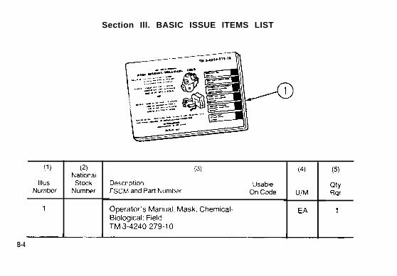
11)
IllusNumber
1
(2)National
StockNumber
Section Ill. BASIC ISSUE ITEMS LIST
(3)
Descrlpt!on UsableFSCM and Part Number On Code
Operator’s Manual, Mask, Chemical-13010gical: FieldTM 3-4240-279-10
(4)
U/M
EA
(5)
QtyF@
1
B-4
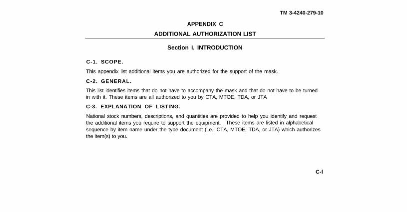
TM 3-4240-279-10
APPENDIX C
ADDITIONAL AUTHORIZATION LIST
Section I. INTRODUCTION
C-1. SCOPE.
This appendix list additional items you are authorized for the support of the mask.
C-2. GENERAL.
This list identifies items that do not have to accompany the mask and that do not have to be turnedin with it. These items are all authorized to you by CTA, MTOE, TDA, or JTA
C-3. EXPLANATION OF LISTING.
National stock numbers, descriptions, and quantities are provided to help you identify and requestthe additional items you require to support the equipment. These items are listed in alphabeticalsequence by item name under the type document (i.e., CTA, MTOE, TDA, or JTA) which authorizesthe item(s) to you.
C-l
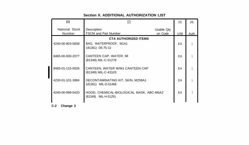
Section II. ADDITIONAL AUTHORIZATION LIST
(2)
Description Usable QtyFSCM and Part Number on Code
CTA AUTHORIZED ITEMS
BAG, WATERPROOF, M1A1181361) D5-75-13
CANTEEN CAP, WATER, Ml(81349) MIL-C-51278
CANTEEN, WATER W/M1 CANTEEN CAP(81349) MIL-C-43103
DECONTAMINATING KIT, SKIN, M258A1181361) MIL-D-51468
HOOD, CHEMICAL-BIOLOGICAL MASK, ABC-M6A2(81349) MIL-H-51291
(1)
National StockNumber
4240-00-803-5839
8465-00-930-2077
8465-01-115-0026
4230-01-101-3984
4240-00-999-0420
(3)
U/M
EA
EA
EA
EA
EA
(4)
Auth
1
1
1
1
1
C-2 Change 3

TM 3-4240-279-10
(1) (2) (3) (4)
National Stock Description Usable QtyNumber FSCM and Part Number on Code U/M Auth
CTA AUTHORIZED ITEMS
INSERTS, OPTICAL’ PR 1
6665-00-050-8529 PAPER, CHEMICAL AGENT DETECTOR, M8 BK 1(81361) D5-67-266
4240-00065-0319 WINTERIZATION KIT, M4, CHEMICAL- EA 1BIOLOGICAL MASK(81361) D5-77-944
* Available by prescription of a medical officer or optometrist (AR 40-63).
Change 3 C-3
APPENDIX D
EXPENDABLE/DURABLE SUPPLIES AND MATERIALS LIST
Section I. INTRODUCTION
D-1. SCOPE.
This listing is for informational purposes only and is not authority to requisition the listed itemsThese items are authorized to you by CTA 50-970, Expendable/Durable Items (except Medical.Class V, Repair Parts, and Heraldic Items), or CTA 8-100, Army Medical DepartmentExpendable/Durable Items.
D-2. EXPLANATION OF COLUMNS.
a. Column (1) - Item Number. This number is assigned to the entry in the listing and isreferenced in the narrative instructions to identify the material (e.g., “Use isopropyl rubbing alcohol,item 6, app D”).
b Column (2) - Level. This column identifies the lowest level of maintenance that requires thelisted item.
C - Operator/Crew
D-0P I N : 0 2 4 2 0 7 - 0 0 3
TM 3-4240-279-10
c. Column (3) - National Stock Number. This is the National stock number assigned to theitem; use it to request or requisition the item.
d. Column (4) - Description. Indicates the Federal item name and, if required, a descriptionto identify the item. The last line for each item indicates the Federal Supply Code for Manufac-turer (FSCM) in parentheses followed by the part number.
e. Column (5) - Unit of Measure (U/M). Indicates the measure used in performing the actualmaintenance function. This measure is expressed by a two-character alphabetical abbreviation(e.g., ea, in., pr). If the unit of measure differs from the unit of issue, requisition the lowest unit ofissue that will satisfy your requirements.
D-1
Section II. EXPENDABLE/DURABLE SUPPLIES AND MATERIALS LIST
D-2
(1)
ITEMNUMBER
6
7
10
(2)
LEVELC
C
C
C
C
(3)NATIONALSTOCK
NUMBER6505-00-655-8366
7240-01-094-4305
7930-00-935-3794
8520-00-228-0598
4240-01-372-3078
TM 3-4240-279-10
(4)
DESCRIPTIONISOPROPYL RUBBING ALCOHOL: bottle,plastic container(56287) PUREPAC
PAIL, UTILITY: plastic, snap-on Iid,5.00 gal (18.93 1)(58536) A-A-332
POLISH, PLASTIC: Liquid, type 1(81348) P-P-560 24 ea bx
SOAP, TOILET nonmedicated, liquid,type 1(81348) P-S-624 (or equivalent)
WIPES, RESPIRATOR CLEANING(50378) 504
PT
EA
PT
GL
BX
Change 2 D-3(D-4 blank)
By Order of the Secretary of the Army:
CARL E. VUONOGeneral, United States Army
Chief of Sfaff
Official:
R. L. DILWORTHBrigadier General, United States Army
The Adjutant General
DISTRIBUTION:
To be distributed in accordance with DA Form 12-28-R, Subscription for Army ChemicalEquipment Publications (LRA).
* U.S. GOVERNMENT PRINTING OFFICE: 1995 388-421/43036
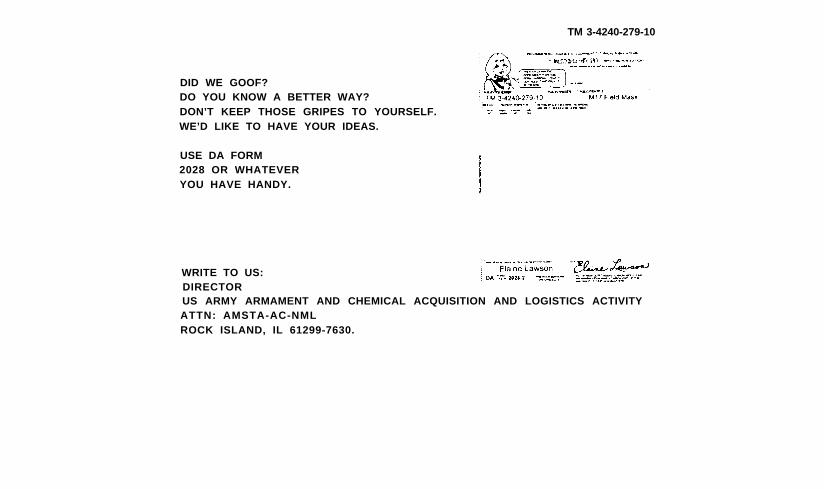
TM 3-4240-279-10
DID WE GOOF?DO YOU KNOW A BETTER WAY?DON’T KEEP THOSE GRIPES TO YOURSELF.WE’D LIKE TO HAVE YOUR IDEAS.
USE DA FORM2028 OR WHATEVERYOU HAVE HANDY.
WRITE TO US:DIRECTORUS ARMY ARMAMENT AND CHEMICAL ACQUISITION AND LOGISTICS ACTIVITYATTN: AMSTA-AC-NMLROCK ISLAND, IL 61299-7630.
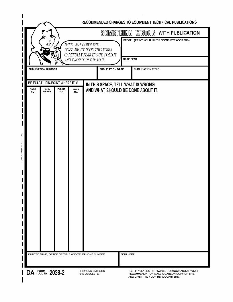
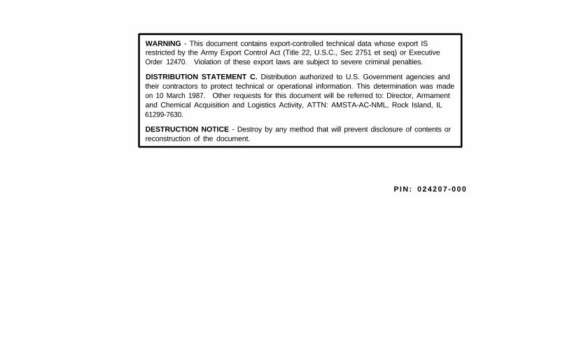
WARNING - This document contains export-controlled technical data whose export ISrestricted by the Army Export Control Act (Title 22, U.S.C., Sec 2751 et seq) or ExecutiveOrder 12470. Violation of these export laws are subject to severe criminal penalties.
DlSTRIBUTlON STATEMENT C. Distribution authorized to U.S. Government agencies andtheir contractors to protect technical or operational information. This determination was madeon 10 March 1987. Other requests for this document will be referred to: Director, Armamentand Chemical Acquisition and Logistics Activity, ATTN: AMSTA-AC-NML, Rock Island, IL61299-7630.
DESTRUCTION NOTICE - Destroy by any method that will prevent disclosure of contents orreconstruction of the document.
P I N : 0 2 4 2 0 7 - 0 0 0