Embed Size (px)
Citation preview

Jitter Reduction Project
Linac Modulator HVPS Upgrade
Initial Test Results
Minh Nguyen
April 25, 2013
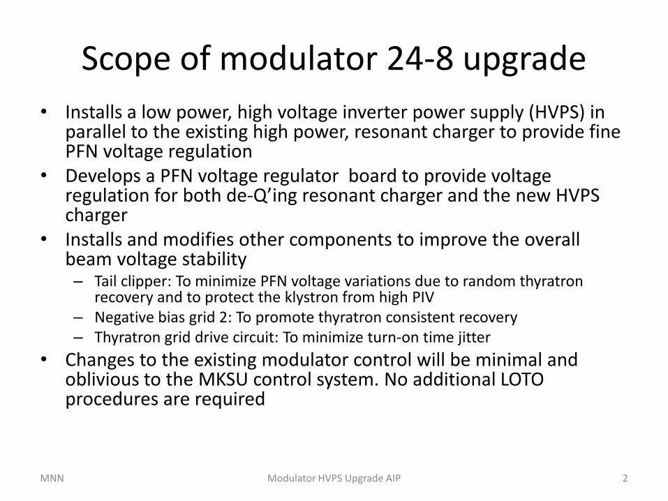
Scope of modulator 24-8 upgrade
• Installs a low power, high voltage inverter power supply (HVPS) in parallel to the existing high power, resonant charger to provide fine PFN voltage regulation
• Develops a PFN voltage regulator board to provide voltage regulation for both de-Q’ing resonant charger and the new HVPS charger
• Installs and modifies other components to improve the overall beam voltage stability– Tail clipper: To minimize PFN voltage variations due to random thyratron
recovery and to protect the klystron from high PIV
– Negative bias grid 2: To promote thyratron consistent recovery
– Thyratron grid drive circuit: To minimize turn-on time jitter
• Changes to the existing modulator control will be minimal and oblivious to the MKSU control system. No additional LOTO procedures are required
MNN 2Modulator HVPS Upgrade AIP

Modulator upgrade circuit (in red lines)Modulator Output: 360 kV, 420 A , 151 MW peak, 91 kW Ave. @ 120 Hz
MNN 3Modulator HVPS Upgrade AIP

Upgrade HV components
MNN Modulator HVPS Upgrade AIP 4
PFN Voltage Regulator Box
De-Q SCR trigger
HVPS control
VVS reference
PFN voltage
feedback
120Vac inputHVPS inhibit
monitor
FB/Error
monitor
Tail Clipper Assembly
SCRTD with -75Vdc Bias

Installed upgrade components
MNN Modulator HVPS Upgrade AIP 5
Ross Divider
TDK Charging Resistors
TDK Reverse Voltage
Protection Diode
Tail Clipper
PFN Voltage Regulator
Box (Outside of Cab 3)
TDK 50kV HVPS
Power Transformer 3-Phase
600Vac In, 208/120Vac Out
Circuit Breaker 208Vac / 20A

Upgraded modulator tests
with PFN voltage regulated at 42kV
MNN Modulator HVPS Upgrade AIP 6
Regulated
PFN voltage
Zoom –in
HVPS charging voltage
(5000/1 ratio)
HVPS charging
current
Resonant charging
voltage (5000/1 ratio)
Thyratron
fire
De-Q’ing
regulation

Klystron backswing voltage
before and after tail clipper installation
MNN Modulator HVPS Upgrade AIP 7
Tail Clipper
Current
10A/div
Voltage scale: 50kV/div

Typical PFN and BV stability
with de-Q’ing regulation only
MNN Modulator HVPS Upgrade AIP 8
• Modulator ran at 42kV PFN, 340kV BV and 120Hz
• Measurement setup: 1000 statistical samples, one-time slot, both scopes are triggered at the same time
• Typical scope rms noise is ~ 1% of vertical setting per division
• Zoom-in PFN and BV voltages are generated by LeCroy DA1855A in comparator mode
PFN stability (rms) = 988uV/8.26V = 120 ppm BV stability (rms) = 7.71mV/62.72V = 123 ppm
Zoom-in
PFN voltage
Zoom-in
Beam voltage
(5000/1 ratio)
PFN voltage
(5000/1 ratio)

Typical PFN and BV stability
with both de-Q’ing and TDK HVPS regulation
MNN Modulator HVPS Upgrade AIP 9
PFN stability (rms) = 131uV/8.29V = 16 ppm BV stability (rms) = 2.58mV/63.24V = 41 ppm

Short term (2-minute intervals)
PFN and BV stability (rms)
MNN Modulator HVPS Upgrade AIP 10
0
10
20
30
40
50
60
1 2 3 4 5 6
Sta
bil
ity
-p
pm
Interval
PFN Stability
BV Stability

20-minute period
PFN and BV stability (rms)
MNN Modulator HVPS Upgrade AIP 11
Time (minutes)
0
10
20
30
40
50
60
70
80
1 5 10 15 20
Sta
bil
ity
(p
pm
)
PFN Stability
BV Stability

Modulator stability is improved
by HVPS charging upgrade
MNN Modulator HVPS Upgrade AIP 12
0
20
40
60
80
100
120
140
1 2 3 4 5 6
Sta
bil
ity
-p
pm
Interval
PFN Stability
BV Stability
PFN-deQ only
BV-deQ only

Some remaining challenges
• TDK-Lambda HVPS fails to start up reliably – Latched off on load fault
• PFN voltage random fluctuations
• Beam voltage random fluctuations and drift
• Relation between Thyratron unstable recovery and random fluctuations
MNN Modulator HVPS Upgrade AIP 13
PFN voltage Klystron beam voltage