Embed Size (px)
Citation preview
JITF and API96/97
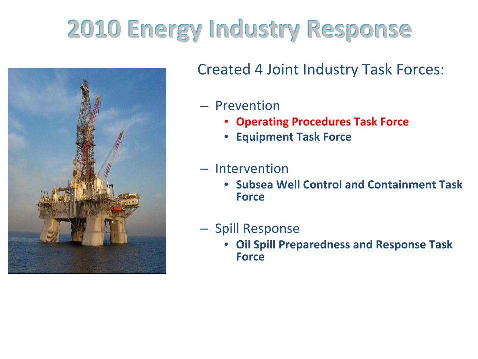
20102010 EnergyEnergy IndustryIndustry ResponseResponseCreated 4 Joint Industry Task Forces:
– Prevention• Operating Procedures Task Force• Equipment Task Force
– Intervention• Subsea Well Control and Containment Task
Force
– Spill Response• Oil Spill Preparedness and Response Task
Force

Restoring Confidence in Deepwater Drilling Operations
Well Containment &
Intervention Capability
Spill Response Capability
Industry DrillingStandards
Safe DrillingOperations

Operating Procedures Task ForceOperating Procedures Task Force
Focus on Drilling & Completion safety, design, procedures and
operations associated Deepwater Wells
• JITF met ~2 weeks in May 2010 to develop recommendations for
DOI focused on (5) areas:1.
Cementing
2.
Loads and Resistance Deepwater Well Design Considerations
3.
Fluid Displacement and Negative Testing
4.
Abandonment and Barriers
5.
Adopt Safety Case & Well Construction Interface

Objectives of JITF
• Make improvements• Reduce risk • Increase environmental protections• Provide rationale for continued drilling in the
Gulf of Mexico
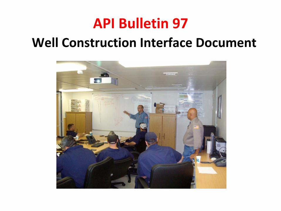
API Bulletin 97 Well Construction Interface Document

WCID Guidelines DOI May 27, 2010 Increased Safety Measure Report

API Bulletin 97
• Initial Plan (mid 2010)
• Safety Case to link Contractors HSE case with Operators Safety Management System (SMS)
(as alluded to in Buffalo report)
– European Safety Case Regime for Gulf Of Mexico
– WCID would be part of the APD process
Revisions• Further meetings with BOEMRE 4th
Qtr 2010
indicated different outcome
– Safety Environment Management System
(SEMS) by operator
with full accountability on operator
– WCID not integral to APD process
– Will be interface (bridging document) between operator
and Rig Contractor and other Contractors. Focus on well
design, execution plans, chain of command and Operator
SEMS interface with Contractor
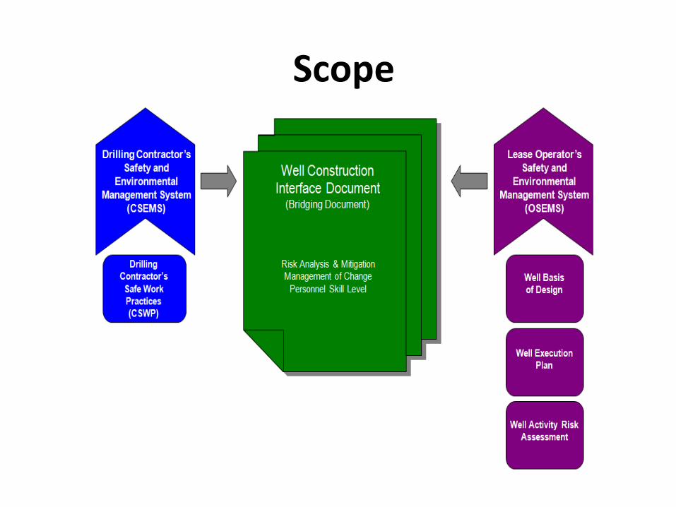
Scope

RP Bulletin 97 WCID Contents
• WCID Guidelines• Drilling Contractor/Operator SEMS Interface• Well Construction (geology, design, barriers,
execution, risk analysis etc)• WCID SEMS Interface Example• WCID Well Construction Interface Example with
Risk analysis example

2011 Results
•
Refined Bulletin 97 and the WCID Example annexes to go to ballot
– Removed references to permitting process and Registered Engineers
– Removed references to equipment certifications
– Removed safety case references.
•
Ballot Bulletin 97 1st
Edition—August
•
Results received in October •
15 affirmative votes / 4 negative votes
•
reviewing several hundred comments

Proactive use of WCID will improve safety and compliance
with SEMS
RP 96 Deepwater Well Design and Construction
•
API (Gary Luquette and David Payne) committed to 2nd
phase of JITF Operating
Procedures for “new standards for DW well designs”. June 2010
•
WG composed of operators, rig contractors, service companies, industry associations
and government regulators
RP 96 Description
• Reviews Deepwater rig systems and BOPs (to show how rigs affect well design)
• Examples of current DW GOM well architecture, and Barrier Philosophy (7 pages)
• Defines load cases (internal and external pressures) and reviews survival design
considerations• Special considerations for drilling and
completions
RP 96 description (Cont)
• Extensive review and examples for conducting displacement operations during drilling and
completion operations• Review of management of change, including
Stop Work Authority• 3 annexes provide examples for barriers
employed during several operations, barrier definitions and examples for negative testing (53 pages total)
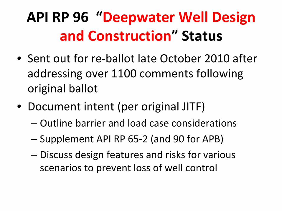
API RP 96 “Deepwater Well Design and Construction”
Status
• Sent out for re‐ballot late October 2010 after addressing over 1100 comments following
original ballot
• Document intent (per original JITF)– Outline barrier and load case considerations– Supplement API RP 65‐2 (and 90 for APB)
– Discuss design features and risks for various scenarios to prevent loss of well control

RP 96 Conclusions• RP 96 is not meant to be a text book for new engineers or
drilling engineers new to Deep Water. It will not define what
design factor to use for burst, for example.
• It is designed to demonstrate and give examples of casing
loads, items to consider when designing wells, and examples of
different well design considerations and design rationale.
• It gives multiple examples (but is not intended to cover all
cases) for considerations when displacing wells and performing
negative tests.
• It provides detailed definitions for barriers.• It reviews operational considerations for drilling and
completions, such as open water work, well testing and more.
• Special operational considerations such as landing strings, APB,
Intelligent Wells

Well design to meet permitting requirements
Well Containment Screening Tool• Introduction –
BOEMRE requirements (NTL‐10)
• Design considerations to demonstrate containment
capability
• Load cases for containment evaluation
• Examples of changes to well design
• Well Containment Screening tools – Level 1 & Level 2
• Version 19 is nearing completion, Cap and Flow
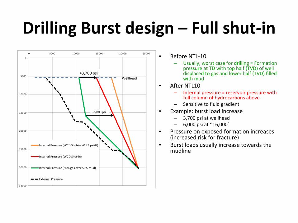
Drilling Burst design – Ful l shut‐in• Before NTL‐10
– Usually, worst case for drilling = Formation
pressure at TD with top half (TVD) of well
displaced to gas and lower half (TVD) filled
with mud• After NTL10
– Internal pressure = reservoir pressure with
full column of hydrocarbons above– Sensitive to fluid gradient
• Example: burst load increase– 3,700 psi at wellhead– 6,000 psi at ~16,000’
• Pressure on exposed formation increases
(increased risk for fracture)
• Burst loads usually increase towards the
mudline
0
5000
10000
15000
20000
25000
30000
35000
0 5000 10000 15000 20000 25000
Internal Pressure (WCD Shut‐in ‐ 0.23 psi/ft)
Internal Pressure (WCD Shut‐in)
Internal Pressure (50% gas over 50% mud)
External Pressure
+6,000 psi
+3,700 psiWellhead

Drilling Collapse design• Before NTL‐10
– Usually, worst case for drilling =
Loss of riser margin or mud drop due
to downhole losses
• After NTL10– Internal pressure = seawater
hydrostatic at mudline with flowing
hydrocarbon gradient below
• Sensitive to produced fluid gradient– Increased APB due to hydrocarbon
flow
• Example: collapse load increase– 8,800 psi at 25,000’
• 8,400 psi due to Internal Pressure
decrease• 400 psi due to APB increase
• Collapse load increases with depth
0
5000
10000
15000
20000
25000
30000
35000
0 5000 10000 15000 20000 25000
Internal Pressure (WCD Flowing ‐ 0.23 psi/ft)
Internal Pressure (WCD Flowing ‐ custom gradient)
External Pressure WCD
Internal Pressure (Loss of riser margin)
External pressure (Loss of riser margin)
8,400 psi
400 psi

Examples of changes to well design
• Burst (typically changes to upper half of well)– Tieback (14”, 13‐3/4”, 13‐5/8”)
– Use 16.04”, 16.15”
instead of 16”
– Higher rating (submudline) hangers
– Or resolve with Cap & Flow
• Collapse (typically changes to lower half of well)– Use heavier 16.04”, 16.15”
instead of 16”
– Use heavier 14”
instead of 13‐5/8”
– Higher rating 14”
hanger systems
– Use long string to control APB (weight limited)
– Lower liners collapse (11‐7/8”
and smaller)
• Formation strength (broaching)– Move mechanical failure point deeper
– Change casing setting depths to take advantage of
strong formation (e.g., salt) or weak/thief zones
– Or resolve with Cap & Flow
• Using existing pre‐NTL10 wells may be challenging– More complicated solutions, e.g., scab liners
HOLE CASINGMD TVD SIZE
KOP
EOB
30" x 32" Hole
36"
28"
18-1/8" x 21" Hole
26" Hole
22.5" x 22"
18" x 17-7/8"
16-1/2" x 19" Hole
14 1/2" x 16-1/2" Hole
14"
16.04" x 16"
TIEBACK (MW = 12.8 ppg)14" x 13-3/4" x 13-5/8"
12-1/4" x 14-1/2" Hole
10-5/8" Hole
11-7/8"

Blowout Risk Assessment JIP (BORA)
• To develop a rapid risk assessment tool to evaluate the risk
related to well design and operations in the Gulf of Mexico.
The risk assessment tool will incorporate three key areas:– Design and Planning– Execution (in the field) – Containment (source control and collection)
• A comparative risk assessment (CRA) will be developed to
help provide a reference point to measure levels of risk.
Thirteen companies have committed to fund this JIP (Nov 1)Similar approach to that used to access risk for anchored rigs
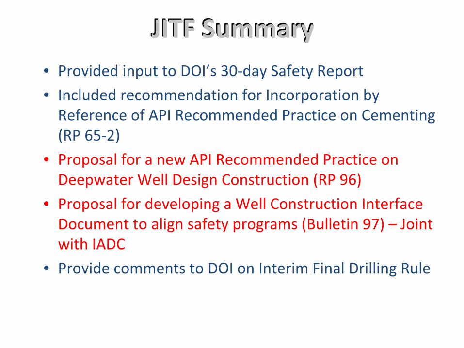
JITFJITF SummarySummary• Provided input to DOI’s 30‐day Safety Report• Included recommendation for Incorporation by
Reference of API Recommended Practice on Cementing (RP 65‐2)
• Proposal for a new API Recommended Practice on Deepwater Well Design Construction (RP 96)
• Proposal for developing a Well Construction Interface Document to align safety programs (Bulletin 97) – Join twith IADC
• Provide comments to DOI on Interim Final Drilling Rule

Normal Clearance Well
30" ~
20"
9.625"
open hole : .
._1ong string
Tight Clearance/long String Intermediate Casing
18"
I production
16" · tieback
9.875"
open hole :
Tight Clearance/ThickWall Conductor Casing
22"
18 "
~=~==!- thick wall
9.875"
open hole
casing
13 %" tieback
production tieback

Comparison of 1990s casing design to current deep well design
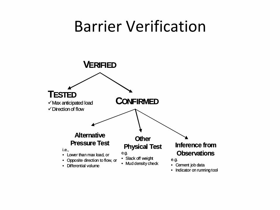
Barrier Verification
VERIFIED
TESTEDMax anticipated loadDirection of flow
CONFIRMED
AlternativePressure Test
i.e., • Lower than max load, or• Opposite direction to flow, or • Differential volume
Other Physical Test
e.g.• Slack off weight• Mud density check
Inference fromObservations
e.g.• Cement job data• Indicator on running tool