Embed Size (px)
Citation preview
JIGS AND FIXTURES 941
JIGS AND FIXTURES
Material for Jig Bushings.—Bushings are generally made of a good grade of tool steel toensure hardening at a fairly low temperature and to lessen the danger of fire cracking. Theycan also be made from machine steel, which will answer all practical purposes, providedthe bushings are properly casehardened to a depth of about 1⁄16 inch. Sometimes, bushingsfor guiding tools may be made of cast iron, but only when the cutting tool is of such adesign that no cutting edges come within the bushing itself. For example, bushings usedsimply to support the smooth surface of a boring-bar or the shank of a reamer might, insome instances, be made of cast iron, but hardened steel bushings should always be usedfor guiding drills, reamers, taps, etc., when the cutting edges come in direct contact withthe guiding surfaces. If the outside diameter of the bushing is very large, as compared withthe diameter of the cutting tool, the cost of the bushing can sometimes be reduced by usingan outer cast-iron body and inserting a hardened tool steel bushing.
When tool steel bushings are made and hardened, it is recommended that A-2 steel beused. The furnace should be set to 1750°F and the bushing placed in the furnace and heldthere approximately 20 minutes after the furnace reaches temperature. Remove the bush-ing and cool in still air. After the part cools to 100–150°F, immediately place in a temper-ing furnace that has been heated to 300°F. Remove the bushing after one hour and cool instill air. If an atmospherically controlled furnace is unavailable, the part should be wrappedin stainless foil to prevent scaling and oxidation at the 1750°F temperature.
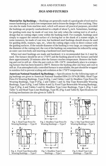
American National Standard Jig Bushings.—Specifications for the following types ofjig bushings are given in American National Standard B94.33-1974 (R1986). Head TypePress Fit Wearing Bushings, Type H (Fig. 1 and Tables 1 and 3); Headless Type Press FitWearing Bushings, Type P (Fig. 2 and Tables 1 and 3); Slip Type Renewable WearingBushings, Type S (Fig. 3 and Tables 4 and 5); Fixed Type Renewable Wearing Bushings,Type F (Fig. 4 and Tables 5 and 6); Headless Type Liner Bushings, Type L (Fig. 5 andTable 7); and Head Type Liner Bushings, Type HL (Fig. 6 and Table 8). Specifications forlocking mechanisms are also given in Table 9.
Fig. 1. Head Type Press Fit-Wearing Bushings — Type H
Fig. 2. Headless Type Press Fit Wearing Bushings — Type P
Fig. 3. Slip Type Renewable Wearing Bushings—Type S
Fig. 4. Fixed Type Renewable Wearing Bushings — Type F
Fig. 5. Headless Type Liner Bushings — Type L
Fig. 6. Head Type Liner Bushings — Type HL
942 JIGS AND FIXTURES
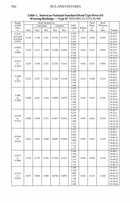
Table 1. American National Standard Head Type Press FitWearing Bushings — Type H ANSI B94.33-1974, R1986
Rangeof HoleSizes
A
Body Diameter BBody
LengthC
RadiusD
HeadDiam.
EMax
HeadThickness
FMax NumberNom
Unfinished Finished
Max Min Max Min
0.0135up to andincluding0.0625
0.156 0.166 0.161 0.1578 0.1575
0.250
0.016 0.250 0.094
H-10-40.312 H-10-50.375 H-10-60.500 H-10-8
0.0630to
0.09950.203 0.213 0.208 0.2046 0.2043
0.250
0.016 0.312 0.094
H-13-40.312 H-13-50.375 H-13-60.500 H-13-80.750 H-13-12
0.1015to
0.14050.250 0.260 0.255 0.2516 0.2513
0.250
0.016 0.375 0.094
H-16-40.312 H-16-50.375 H-16-60.500 H-16-80.750 H-16-12
0.1406to
0.18750.312 0.327 0.322 0.3141 0.3138
0.250
0.031 0.438 0.125
H-20-40.312 H-20-50.375 H-20-60.500 H-20-80.750 H-20-121.000 H-20-16
0.189to
0.25000.406 0.421 0.416 0.4078 0.4075
0.250
0.031 0.531 0.156
H-26-40.312 H-26-50.375 H-26-60.500 H-26-80.750 H-26-121.000 H-26-161.375 H-26-221.750 H-26-28
0.2570to
0.31250.500 0.520 0.515 0.5017 0.5014
0.312
0.047 0.625 0.219
H-32-50.375 H-32-60.500 H-32-80.750 H-32-121.000 H-32-161.375 H-32-221.750 H-32-28
0.3160to
0.42190.625 0.645 0.640 0.6267 0.6264
0.312
0.047 0.812 0.219
H-40-50.375 H-40-60.500 H-40-80.750 H-40-121.000 H-40-161.375 H-40-221.750 H-40-282.125 H-40-34
0.4375to
0.50000.750 0.770 0.765 0.7518 0.7515
0.500
0.062 0.938 0.219
H-48-80.750 H-48-121.000 H-48-161.375 H-48-221.750 H-29-282.125 H-48-34
0.5156to
0.62500.875 0.895 0.890 0.8768 0.8765
0.500
0.062 0.125 0.250
H-56-80.750 H-56-121.000 H-56-161.375 H-56-221.750 H-56-282.125 H-56-342.500 H-56-40
JIGS AND FIXTURES 943
All dimensions are in inches.See also Table 3 for additional specifications.
0.6406to
0.75001.000 1.020 1.015 1.0018 1.0015
0.500
0.094 1.250 0.312
H-64-80.750 H-64-121.000 H-64-161.375 H-64-221.750 H-64-282.125 H-64-342.500 H-64-40
0.7656to
1.00001.375 1.395 1.390 1.3772 1.3768
0.750
0.094 1.625 0.375
H-88-121.000 H-88-161.375 H-88-221.750 H-88-282.125 H-88-342.500 H-88-40
1.0156to
1.37501.750 1.770 1.765 1.7523 1.7519
1.000
0.094 2.000 0.375
H-112-161.375 H-112-221.750 H-112-282.125 H-112-342.500 H-112-403.000 H-112-48
1.3906to
1.75002.250 2.270 2.265 2.2525 2.2521
1.000
0.094 2.500 0.375
H-144-161.375 H-144-221.750 H-144-282.125 H-144-342.500 H-144-403.000 H-144-48
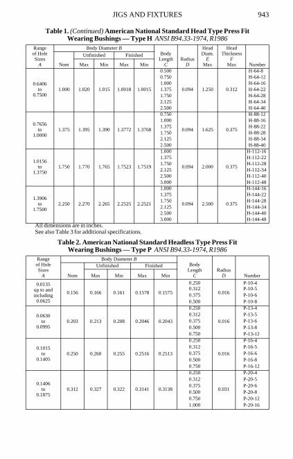
Table 2. American National Standard Headless Type Press Fit Wearing Bushings — Type P ANSI B94.33-1974, R1986
Rangeof HoleSizes
A
Body Diameter BBody
LengthC
RadiusD NumberNom
Unfinished Finished
Max Min Max Min
0.0135up to andincluding0.0625
0.156 0.166 0.161 0.1578 0.1575
0.250
0.016
P-10-40.312 P-10-50.375 P-10-60.500 P-10-8
0.0630to
0.09950.203 0.213 0.208 0.2046 0.2043
0.250
0.016
P-13-40.312 P-13-50.375 P-13-60.500 P-13-80.750 P-13-12
0.1015to
0.14050.250 0.260 0.255 0.2516 0.2513
0.250
0.016
P-16-40.312 P-16-50.375 P-16-60.500 P-16-80.750 P-16-12
0.1406to
0.18750.312 0.327 0.322 0.3141 0.3138
0.250
0.031
P-20-40.312 P-20-50.375 P-20-60.500 P-20-80.750 P-20-121.000 P-20-16
Table 1. (Continued) American National Standard Head Type Press FitWearing Bushings — Type H ANSI B94.33-1974, R1986
Rangeof HoleSizes
A
Body Diameter BBody
LengthC
RadiusD
HeadDiam.
EMax
HeadThickness
FMax NumberNom
Unfinished Finished
Max Min Max Min
944 JIGS AND FIXTURES
All dimensions are in inches. See Table 3 for additional specifications.
0.1890to
0.25000.406 0.421 0.416 0.4078 0.4075
0.250
0.031
P-26-40.312 P-26-50.375 P-26-60.500 P-26-80.750 P-26-121.000 P-26-161.375 P-26-221.750 P-26-28
0.2570to
0.31250.500 0.520 0.515 0.5017 0.5014
0.312
0.047
P-32-50.375 P-32-60.500 P-32-80.750 P-32-121.000 P-32-161.375 P-32-221.750 P-32-28
0.3160to
0.42190.625 0.645 0.640 0.6267 0.6264
0.312
0.047
P-40-50.375 P-40-60.500 P-40-80.750 P-40-121.000 P-40-161.375 P-40-221.750 P-40-282.125 P-40-34
0.4375 to 0.5000 0.750 0.770 0.765 0.7518 0.7515
0.500
0.062
P-48-80.750 P-48-121.000 P-48-161.375 P-48-221.750 P-48-282.125 P-48-34
0.5156to
0.62500.875 0.895 0.890 0.8768 0.8765
0.500
0.062
P-56-80.750 P-56-121.000 P-56-161.375 P-56-221.750 P-56-282.125 P-56-342.500 P-56-40
0.6406to
0.75001.000 1.020 1.015 1.0018 1.0015
0.500
0.062
P-64-80.750 P-64-121.000 P-64-161.375 P-64-221.750 P-64-282.125 P-64-342.500 P-64-40
0.7656to
1.00001.375 1.395 1.390 1.3772 1.3768
0.750
0.094
P-88-121.000 P-88-161.375 P-88-221.750 P-88-282.125 P-88-342.500 P-88-40
1.0156to
1.37501.750 1.770 1.765 1.7523 1.7519
1.000
0.094
P-112-161.375 P-112-221.750 P-112-282.125 P-112-342.500 P-112-403.000 P-112-48
1.3906to
1.75002.250 2.270 2.265 2.2525 2.2521
1.000
0.094
P-144-161.375 P-144-221.750 P-144-282.125 P-144-342.500 P-144-403.000 P-144-48
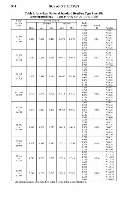
Table 2. American National Standard Headless Type Press Fit Wearing Bushings — Type P ANSI B94.33-1974, R1986
Rangeof HoleSizes
A
Body Diameter BBody
LengthC
RadiusD NumberNom
Unfinished Finished
Max Min Max Min

JIGS AND FIXTURES 945
Table 3. Specifications for Head Type H and Headless Type P Press Fit Wearing Bushings ANSI B94.33-1974, R1986
All dimensions are in inches.
X indicates no counterbore.
+ indicates not American National Standard
All dimensions given in inches. Tolerance on dimensions where not otherwise specified shall be ±0.010 inch.Size and type of chamfer on lead end to be manufacturer's option.The length, C, is the overall length for the headless type and length underhead for the head type.The head design shall be in accordance with the manufacturer's practice.Diameter A must be concentric to diameter B within 0.0005 T.I.V. on finish ground bushings.The body diameter, B, for unfinished bushings is larger than the nominal diameter in order to provide grinding stock for fitting to
jig plate holes. The grinding allowance is:0.005 to 0.010 in. for sizes 0.156, 0.203 and 0.250 in.0.010 to 0.015 in. for sizes 0.312 and 0.406 in.0.015 to 0.020 in. for sizes 0.500 in. and up.
Hole sizes are in accordance with American National Standard Twist Drill Sizes.The maximum and minimum values of the hole size, A, shall be as follows:
Nominal Size of Hole Maximum MinimumAbove 0.0135 to 0.2500 in., incl. Nominal + 0.0004 in. Nominal + 0.0001 in.Above 0.2500 to 0.7500 in., incl. Nominal + 0.0005 in. Nominal + 0.0001 in.Above 0.7500 to 1.5000 in., incl. Nominal + 0.0006 in. Nominal + 0.0002 in.Above 1.5000 in. Nominal + 0.0007 in. Nominal + 0.0003 in.
Bushings in the size range from 0.0135 through 0.3125 will be counterbored to provide for lubrication and chip clearance.Bushings without counterbore are optional and will be furnished upon request.The size of the counterbore shall be inside diameter of the bushing + 0.031 inch.The included angle at the bottom of the counterbore shall be 118 deg, ± 2 deg.The depth of the counterbore shall be in accordance with the table below to provide adequate drill bearing.
BodyLength
Drill Bushing Hole Size0.0135 to0.0625
0.0630 to0.0995
0.1015 to0.1405
0.1406 to0.1875
0.1890 to0.2500
0.2570 to0.3125
P H P H P H P H P H P HMinimum Drill Bearing Length—Inch
0.250 X 0.250 X X X X X X X X X X0.312 X 0.250 X X X X X X X X X X0.375 0.250 0.250 X X X X X X X X X X0.500 0.250 0.250 X 0.312 X 0.312 X 0.375 X X X X0.750 + + 0.375 0.375 0.375 0.375 X 0.375 X X X X1.000 + + + + + + 0.625 0.625 0.625 0.625 0.625 0.6251.375 + + + + + + + + 0.625 0.625 0.625 0.6251.750 + + + + + + + + 0.625 0.625 0.625 0.625
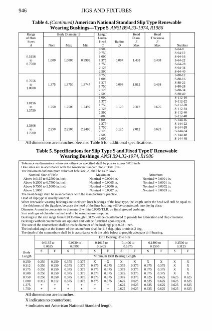
Table 4. American National Standard Slip Type Renewable Wearing Bushings—Type S ANSI B94.33-1974, R1986
Rangeof HoleSizes
A
Body Diameter B LengthUnder-Head
CRadius
D
HeadDiam.
EMax
HeadThickness
FMax NumberNom Max Min
0.0135up to andincluding0.0469
0.188 0.1875 0.1873
0.250
0.031 0.312 0.188
S-12-40.312 S-12-50.375 S-12-60.500 S-12-8
0.0492to
0.15620.312 0.3125 0.3123
0.312
0.047 0.562 0.375
S-20-50.500 S-20-80.750 S-20-121.000 S-20-16
0.1570to
0.31250.500 0.5000 0.4998
0.312
0.047 0.812 0.438
S-32-50.500 S-32-80.750 S-32-121.000 S-32-161.375 S-32-221.750 S-32-28
0.3160to
0.50000.750 0.7500 0.7498
0.500
0.094 1.062 0.438
S-48-80.750 S-48-121.000 S-48-161.375 S-48-221.750 S-48-282.125 S-48-34
946 JIGS AND FIXTURES
All dimensions are in inches. See also Table 5 for additional specifications.
Table 5. Specifications for Slip Type S and Fixed Type F Renewable Wearing Bushings ANSI B94.33-1974, R1986
All dimensions are in inches.X indicates no counterbore.+ indicates not American National Standard length.
0.5156to
0.75001.000 1.0000 0.9998
0.500
0.094 1.438 0.438
S-64-80.750 S-64-121.000 S-64-161.375 S-64-221.750 S-64-282.125 S-64-342.500 S-64-40
0.7656to
1.00001.375 1.3750 1.3747
0.750
0.094 1.812 0.438
S-88-121.000 S-88-161.375 S-88-221.750 S-88-282.125 S-88-342.500 S-88-40
1.0156to
1.37501.750 1.7500 1.7497
1.000
0.125 2.312 0.625
S-112-161.375 S-112-221.750 S-112-282.125 S-112-342.500 S-112-403.000 S-112-48
1.3906to
1.75002.250 2.2500 2.2496
1.000
0.125 2.812 0.625
S-144-161.375 S-144-221.750 S-144-282.125 S-144-342.500 S-144-403.000 S-144-48
Tolerance on dimensions where not otherwise specified shall be plus or minus 0.010 inch.Hole sizes are in accordance with the American Standard Twist Drill Sizes.The maximum and minimum values of hole size, A, shall be as follows:
Nominal Size of Hole Maximum MinimumAbove 0.0135 to 0.2500 in. incl. Nominal + 0.0004 in. Nominal + 0.0001 in.Above 0.2500 to 0.7500 in. incl. Nominal + 0.0005 in. Nominal + 0.0001 in.Above 0.7500 to 1.5000 in. incl. Nominal + 0.0006 in. Nominal + 0.0002 in.Above 1.5000 Nominal + 0.0007 in. Nominal + 0.0003 in.
The head design shall be in accordance with the manufacturer's practice.Head of slip type is usually knurled.When renewable wearing bushings are used with liner bushings of the head type, the length under the head will still be equal to
the thickness of the jig plate, because the head of the liner bushing will be countersunk into the jig plate.Diameter A must be concentric to diameter B within 0.0005 T.I.R. on finish ground bushings.Size and type of chamfer on lead end to be manufacturer's option.Bushings in the size range from 0.0135 through 0.3125 will be counterbored to provide for lubrication and chip clearance.Bushings without counterbore are optional and will be furnished upon request.The size of the counterbore shall be inside diameter of the bushings plus 0.031 inch.The included angle at the bottom of the counterbore shall be 118 deg., plus or minus 2 deg.The depth of the counterbore shall be in accordance with the table below to provide adequate drill bearing.
BodyLength
Drill Bearing Hole Size
0.0135 to0.0625
0.0630 to0.0995
0.1015 to0.1405
0.1406 to0.1875
0.1890 to0.2500
0.2500 to0.3125
S F S F S F S F S F S F
Minimum Drill Bearing Length
0.250 0.250 0.250 0.375 0.375 X X X X X X X X0.312 0.250 0.250 0.375 0.375 0.375 0.375 0.375 0.375 0.375 0.375 X X0.375 0.250 0.250 0.375 0.375 0.375 0.375 0.375 0.375 0.375 0.375 X X0.500 0.250 0.250 0.375 0.375 0.375 0.375 0.375 0.375 0.375 0.375 X X0.750 0.250 0.250 0.375 0.375 0.375 0.375 0.375 0.375 0.625 0.625 0.625 0.6251.000 0.312 0.312 0.375 0.375 0.375 0.375 0.625 0.625 0.625 0.625 0.625 0.6251.375 + + + + + + 0.625 0.625 0.625 0.625 0.625 0.6251.750 + + + + + + 0.625 0.625 0.625 0.625 0.625 0.625
Table 4. (Continued) American National Standard Slip Type Renewable Wearing Bushings—Type S ANSI B94.33-1974, R1986
Rangeof HoleSizes
A
Body Diameter B LengthUnder-Head
CRadius
D
HeadDiam.
EMax
HeadThickness
FMax NumberNom Max Min
JIGS AND FIXTURES 947
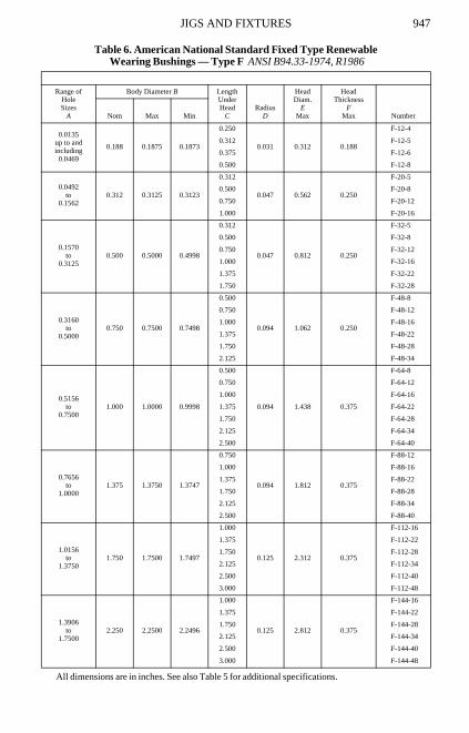
Table 6. American National Standard Fixed Type Renewable Wearing Bushings — Type F ANSI B94.33-1974, R1986
All dimensions are in inches. See also Table 5 for additional specifications.
Range ofHoleSizes
A
Body Diameter B LengthUnderHead
CRadius
D
HeadDiam.
EMax
HeadThickness
FMax NumberNom Max Min
0.0135up to andincluding0.0469
0.188 0.1875 0.1873
0.250
0.031 0.312 0.188
F-12-4
0.312 F-12-5
0.375 F-12-6
0.500 F-12-8
0.0492to
0.15620.312 0.3125 0.3123
0.312
0.047 0.562 0.250
F-20-5
0.500 F-20-8
0.750 F-20-12
1.000 F-20-16
0.1570to
0.31250.500 0.5000 0.4998
0.312
0.047 0.812 0.250
F-32-5
0.500 F-32-8
0.750 F-32-12
1.000 F-32-16
1.375 F-32-22
1.750 F-32-28
0.3160to
0.50000.750 0.7500 0.7498
0.500
0.094 1.062 0.250
F-48-8
0.750 F-48-12
1.000 F-48-16
1.375 F-48-22
1.750 F-48-28
2.125 F-48-34
0.5156to
0.75001.000 1.0000 0.9998
0.500
0.094 1.438 0.375
F-64-8
0.750 F-64-12
1.000 F-64-16
1.375 F-64-22
1.750 F-64-28
2.125 F-64-34
2.500 F-64-40
0.7656to
1.00001.375 1.3750 1.3747
0.750
0.094 1.812 0.375
F-88-12
1.000 F-88-16
1.375 F-88-22
1.750 F-88-28
2.125 F-88-34
2.500 F-88-40
1.0156to
1.37501.750 1.7500 1.7497
1.000
0.125 2.312 0.375
F-112-16
1.375 F-112-22
1.750 F-112-28
2.125 F-112-34
2.500 F-112-40
3.000 F-112-48
1.3906to
1.75002.250 2.2500 2.2496
1.000
0.125 2.812 0.375
F-144-16
1.375 F-144-22
1.750 F-144-28
2.125 F-144-34
2.500 F-144-40
3.000 F-144-48
948 JIGS AND FIXTURES
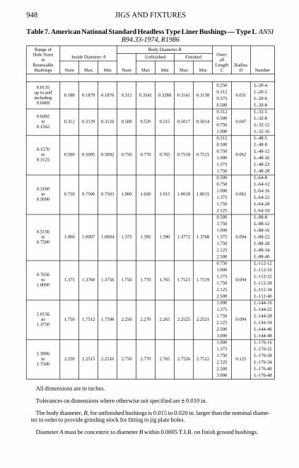
Table 7. American National Standard Headless Type Liner Bushings — Type L ANSI B94.33-1974, R1986
All dimensions are in inches.
Tolerances on dimensions where otherwise not specified are ± 0.010 in.
The body diameter, B, for unfinished bushings is 0.015 to 0.020 in. larger than the nominal diame-ter in order to provide grinding stock for fitting to jig plate holes.
Diameter A must be concentric to diameter B within 0.0005 T.I.R. on finish ground bushings.
Range ofHole Sizes
inRenewableBushings
Inside Diameter A
Body Diameter BOver-
allLength
CRadius
D NumberNom
Unfinished Finished
Nom Max Min Max Min Max Min
0.0135up to andincluding0.0469
0.188 0.1879 0.1876 0.312 0.3341 0.3288 0.3141 0.3138
0.250
0.031
L-20-4
0.312 L-20-5
0.375 L-20-6
0.500 L-20-8
0.0492to
0.15620.312 0.3129 0.3126 0.500 0.520 0.515 0.5017 0.5014
0.312
0.047
L-32-5
0.500 L-32-8
0.750 L-32-12
1.000 L-32-16
0.1570to
0.31250.500 0.5005 0.5002 0.750 0.770 0.765 0.7518 0.7515
0.312
0.062
L-48-5
0.500 L-48-8
0.750 L-48-12
1.000 L-48-16
1.375 L-48-22
1.750 L-48-28
0.3160to
0.50000.750 0.7506 0.7503 1.000 1.020 1.015 1.0018 1.0015
0.500
0.062
L-64-8
0.750 L-64-12
1.000 L-64-16
1.375 L-64-22
1.750 L-64-28
2.125 L-64-34
0.5156to
0.75001.000 1.0007 1.0004 1.375 1.395 1.390 1.3772 1.3768
0.500
0.094
L-88-8
1.750 L-88-12
1.000 L-88-16
1.375 L-88-22
1.750 L-88-28
2.125 L-88-34
2.500 L-88-40
0.7656to
1.00001.375 1.3760 1.3756 1.750 1.770 1.765 1.7523 1.7519
0.750
0.094
L-112-12
1.000 L-112-16
1.375 L-112-22
1.750 L-112-28
2.125 L-112-34
2.500 L-112-40
1.0156to
1.37501.750 1.7512 1.7508 2.250 2.270 2.265 2.2525 2.2521
1.000
0.094
L-144-16
1.375 L-144-22
1.750 L-144-28
2.125 L-144-34
2.500 L-144-40
3.000 L-144-48
1.3906to
1.75002.250 2.2515 2.2510 2.750 2.770 2.765 2.7526 2.7522
1.000
0.125
L-176-16
1.375 L-176-22
1.750 L-176-28
2.125 L-176-34
2.500 L-176-40
3.000 L-176-48
JIGS AND FIXTURES 949
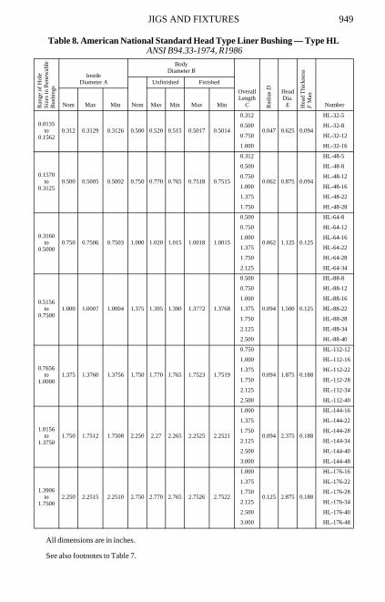
Table 8. American National Standard Head Type Liner Bushing — Type HL ANSI B94.33-1974, R1986
All dimensions are in inches.
See also footnotes to Table 7.
Ra
nge
of H
ole
Siz
es in
Ren
ewab
leB
ushi
ngs
InsideDiameter A
BodyDiameter B
OverallLength
C Rad
ius D Head
Dia. E H
ea
d T
hic
kne
ssF
Ma
x
NumberNom
Unfinished Finished
Nom Max Min Max Min Max Min
0.0135to
0.15620.312 0.3129 0.3126 0.500 0.520 0.515 0.5017 0.5014
0.312
0.047 0.625 0.094
HL-32-5
0.500 HL-32-8
0.750 HL-32-12
1.000 HL-32-16
0.1570to
0.31250.500 0.5005 0.5002 0.750 0.770 0.765 0.7518 0.7515
0.312
0.062 0.875 0.094
HL-48-5
0.500 HL-48-8
0.750 HL-48-12
1.000 HL-48-16
1.375 HL-48-22
1.750 HL-48-28
0.3160to
0.50000.750 0.7506 0.7503 1.000 1.020 1.015 1.0018 1.0015
0.500
0.062 1.125 0.125
HL-64-8
0.750 HL-64-12
1.000 HL-64-16
1.375 HL-64-22
1.750 HL-64-28
2.125 HL-64-34
0.5156to
0.75001.000 1.0007 1.0004 1.375 1.395 1.390 1.3772 1.3768
0.500
0.094 1.500 0.125
HL-88-8
0.750 HL-88-12
1.000 HL-88-16
1.375 HL-88-22
1.750 HL-88-28
2.125 HL-88-34
2.500 HL-88-40
0.7656to
1.00001.375 1.3760 1.3756 1.750 1.770 1.765 1.7523 1.7519
0.750
0.094 1.875 0.188
HL-112-12
1.000 HL-112-16
1.375 HL-112-22
1.750 HL-112-28
2.125 HL-112-34
2.500 HL-112-40
1.0156to
1.37501.750 1.7512 1.7508 2.250 2.27 2.265 2.2525 2.2521
1.000
0.094 2.375 0.188
HL-144-16
1.375 HL-144-22
1.750 HL-144-28
2.125 HL-144-34
2.500 HL-144-40
3.000 HL-144-48
1.3906to
1.75002.250 2.2515 2.2510 2.750 2.770 2.765 2.7526 2.7522
1.000
0.125 2.875 0.188
HL-176-16
1.375 HL-176-22
1.750 HL-176-28
2.125 HL-176-34
2.500 HL-176-40
3.000 HL-176-48
950 JIGS AND FIXTURES
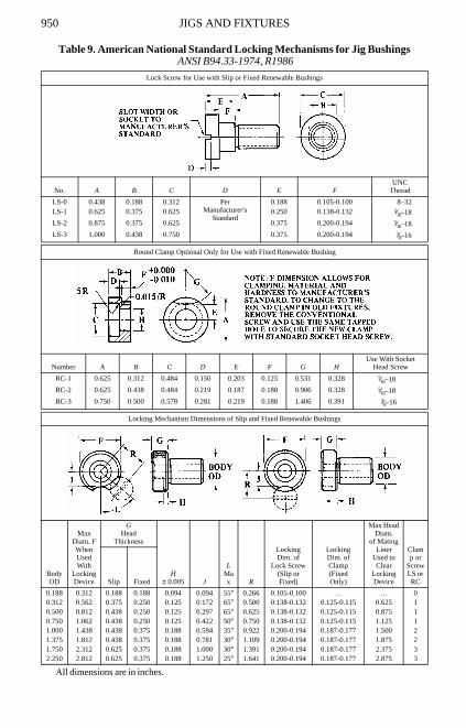
Table 9. American National Standard Locking Mechanisms for Jig Bushings ANSI B94.33-1974, R1986
All dimensions are in inches.
Lock Screw for Use with Slip or Fixed Renewable Bushings
No. A B C D E FUNC
Thread
LS-0 0.438 0.188 0.312 PerManufacturer's
Standard
0.188 0.105-0.100 8–32LS-1 0.625 0.375 0.625 0.250 0.138-0.132 5⁄16–18
LS-2 0.875 0.375 0.625 0.375 0.200-0.194 5⁄16–18
LS-3 1.000 0.438 0.750 0.375 0.200-0.194 3⁄8–16
Round Clamp Optional Only for Use with Fixed Renewable Bushing
Number A B C D E F G HUse With Socket
Head Screw
RC-1 0.625 0.312 0.484 0.150 0.203 0.125 0.531 0.328 5⁄16–18
RC-2 0.625 0.438 0.484 0.219 0.187 0.188 0.906 0.328 5⁄16–18
RC-3 0.750 0.500 0.578 0.281 0.219 0.188 1.406 0.391 3⁄8–16
Locking Mechanism Dimensions of Slip and Fixed Renewable Bushings
BodyOD
Max Diam. FWhen Used With
Locking Device
GHead
Thickness
H± 0.005 J
LMax R
LockingDim. of
Lock Screw(Slip orFixed)
LockingDim. ofClamp(FixedOnly)
Max Head Diam.
of Mating Liner
Used to Clear
Locking Device
Clamp or
ScrewLS or RCSlip Fixed
0.188 0.312 0.188 0.188 0.094 0.094 55° 0.266 0.105-0.100 … … 00.312 0.562 0.375 0.250 0.125 0.172 65° 0.500 0.138-0.132 0.125-0.115 0.625 10.500 0.812 0.438 0.250 0.125 0.297 65° 0.625 0.138-0.132 0.125-0.115 0.875 10.750 1.062 0.438 0.250 0.125 0.422 50° 0.750 0.138-0.132 0.125-0.115 1.125 11.000 1.438 0.438 0.375 0.188 0.594 35° 0.922 0.200-0.194 0.187-0.177 1.500 21.375 1.812 0.438 0.375 0.188 0.781 30° 1.109 0.200-0.194 0.187-0.177 1.875 21.750 2.312 0.625 0.375 0.188 1.000 30° 1.391 0.200-0.194 0.187-0.177 2.375 32.250 2.812 0.625 0.375 0.188 1.250 25° 1.641 0.200-0.194 0.187-0.177 2.875 3
JIG BUSHINGS 951
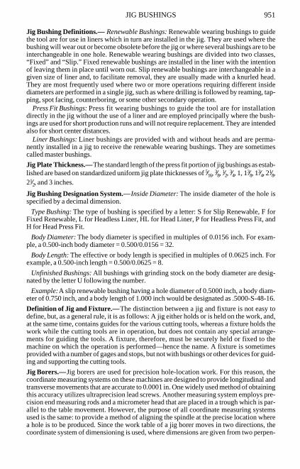
Jig Bushing Definitions.— Renewable Bushings: Renewable wearing bushings to guidethe tool are for use in liners which in turn are installed in the jig. They are used where thebushing will wear out or become obsolete before the jig or where several bushings are to beinterchangeable in one hole. Renewable wearing bushings are divided into two classes,“Fixed” and “Slip.” Fixed renewable bushings are installed in the liner with the intentionof leaving them in place until worn out. Slip renewable bushings are interchangeable in agiven size of liner and, to facilitate removal, they are usually made with a knurled head.They are most frequently used where two or more operations requiring different insidediameters are performed in a single jig, such as where drilling is followed by reaming, tap-ping, spot facing, counterboring, or some other secondary operation.
Press Fit Bushings: Press fit wearing bushings to guide the tool are for installationdirectly in the jig without the use of a liner and are employed principally where the bush-ings are used for short production runs and will not require replacement. They are intendedalso for short center distances.
Liner Bushings: Liner bushings are provided with and without heads and are perma-nently installed in a jig to receive the renewable wearing bushings. They are sometimescalled master bushings.
Jig Plate Thickness.—The standard length of the press fit portion of jig bushings as estab-lished are based on standardized uniform jig plate thicknesses of 5⁄16, 3⁄8, 1⁄2, 3⁄4, 1, 13⁄8, 13⁄4, 21⁄8,21⁄2, and 3 inches.
Jig Bushing Designation System.—Inside Diameter: The inside diameter of the hole isspecified by a decimal dimension.
Type Bushing: The type of bushing is specified by a letter: S for Slip Renewable, F forFixed Renewable, L for Headless Liner, HL for Head Liner, P for Headless Press Fit, andH for Head Press Fit.
Body Diameter: The body diameter is specified in multiples of 0.0156 inch. For exam-ple, a 0.500-inch body diameter = 0.500/0.0156 = 32.
Body Length: The effective or body length is specified in multiples of 0.0625 inch. Forexample, a 0.500-inch length = 0.500/0.0625 = 8.
Unfinished Bushings: All bushings with grinding stock on the body diameter are desig-nated by the letter U following the number.
Example:A slip renewable bushing having a hole diameter of 0.5000 inch, a body diam-eter of 0.750 inch, and a body length of 1.000 inch would be designated as .5000-S-48-16.
Definition of Jig and Fixture.—The distinction between a jig and fixture is not easy todefine, but, as a general rule, it is as follows: A jig either holds or is held on the work, and,at the same time, contains guides for the various cutting tools, whereas a fixture holds thework while the cutting tools are in operation, but does not contain any special arrange-ments for guiding the tools. A fixture, therefore, must be securely held or fixed to themachine on which the operation is performed—hence the name. A fixture is sometimesprovided with a number of gages and stops, but not with bushings or other devices for guid-ing and supporting the cutting tools.
Jig Borers.—Jig borers are used for precision hole-location work. For this reason, thecoordinate measuring systems on these machines are designed to provide longitudinal andtransverse movements that are accurate to 0.0001 in. One widely used method of obtainingthis accuracy utilizes ultraprecision lead screws. Another measuring system employs pre-cision end measuring rods and a micrometer head that are placed in a trough which is par-allel to the table movement. However, the purpose of all coordinate measuring systemsused is the same: to provide a method of aligning the spindle at the precise location wherea hole is to be produced. Since the work table of a jig borer moves in two directions, thecoordinate system of dimensioning is used, where dimensions are given from two perpen-
952 JIG BORING
dicular reference axes, usually the sides of the workpiece, frequently its upper left-handcorner. See Fig. 1C.
Jig-Boring Practice.—The four basic steps to follow to locate and machine a hole on a jigborer are: 1) align and clamp the workpiece on the jig-borer table; 2) locate the two refer-ence axes of the workpiece with respect to the jig-borer spindle; 3) locate the hole to bemachined; and 4) drill and bore the hole to size.
Align and Clamp the Workpiece: The first consideration in placing the workpiece on thejig-borer table should be the relation of the coordinate measuring system of the jig borer tothe coordinate dimensions on the drawing. Therefore, the coordinate measuring system isdesigned so that the readings of the coordinate measurements are direct when the table ismoved toward the left and when it is moved toward the column of the jig borer. The resultwould be the same if the spindle were moved toward the right and away from the column,with the workpiece situated in such a position that one reference axis is located at the leftand the other axis at the back, toward the column.
If the holes to be bored are to pass through the bottom of the workpiece, then the work-piece must be placed on precision parallel bars. In order to prevent the force exerted by theclamps from bending the workpiece the parallel bars are placed directly under the clamps,which hold the workpiece on the table. The reference axes of the workpiece must also bealigned with respect to the transverse and longitudinal table movements before it is firmlyclamped. This alignment can be done with a dial-test indicator held in the spindle of the jigborer and bearing against the longitudinal reference edge. As the table is traversed in thelongitudinal direction, the workpiece is adjusted until the dial-test indicator readings arethe same for all positions.
Locate the Two Reference Axes of the Workpiece with Respect to the Spindle: The j ig -borer table is now moved to position the workpiece in a precise and known location fromwhere it can be moved again to the location of the holes to be machined. Since all the holesare dimensioned from the two reference axes, the most convenient position to start from iswhere the axis of the jig-borer spindle and the intersection of the two workpiece referenceaxes are aligned. This is called the starting position, which is similar to a zero referenceposition. When so positioned, the longitudinal and transverse measuring systems of the jigborer are set to read zero. Occasionally, the reference axes are located outside the body ofthe workpiece: a convenient edge or hole on the workpiece is picked up as the starting posi-tion, and the dimensions from this point to the reference axes are set on the positioningmeasuring system.
Locate the Hole: Precise coordinate table movements are used to position the workpieceso that the spindle axis is located exactly where the hole is to be machined. When the mea-suring system has been set to zero at the starting position, the coordinate readings at thehole location will be the same as the coordinate dimensions of the hole center.
The movements to each hole must be made in one direction for both the transverse andlongitudinal directions, to eliminate the effect of any backlash in the lead screw. The usualtable movements are toward the left and toward the column.
The most convenient sequence on machines using micrometer dials as position indica-tors (machines with lead screws) is to machine the hole closest to the starting position firstand then the next closest, and so on. On jig borers using end measuring rods, the oppositesequence is followed: The farthest hole is machined first and then the next farthest, and soon, since it is easier to remove end rods and replace them with shorter rods.
JIG BORING 953
Drill and Bore Hole to Size: The sequence of operations used to produce a hole on a jigborer is as follows: 1) a short, stiff drill, such as a center drill, that will not deflect when cut-ting should be used to spot a hole when the work and the axis of the machine tool spindleare located at the exact position where the hole is wanted; 2) the initial hole is made by atwist drill; and 3) a single-point boring tool that is set to rotate about the axis of themachine tool spindle is then used to generate a cut surface that is concentric to the axis ofrotation.
Heat will be generated by the drilling operation, so it is good practice to drill all the holesfirst, and then allow the workpiece to cool before the holes are bored to size.
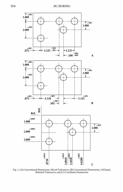
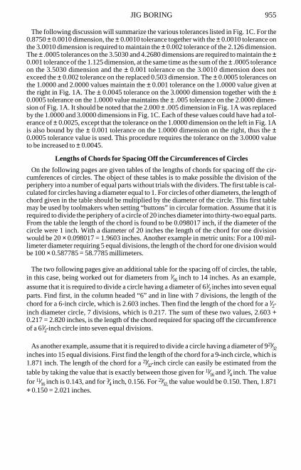
Transfer of Tolerances.—All of the dimensions that must be accurately held on preci-sion machines and engine parts are usually given a tolerance. And when such dimensionsare changed from the conventional to the coordinate system of dimensioning, the toler-ances must also be included. Because of their importance, the transfer of the tolerancesmust be done with great care, keeping in mind that the sum of the tolerances of any pair ofdimensions in the coordinate system must not be larger than the tolerance of the dimensionthat they replaced in the conventional system. An example is given in Fig. 1.
The first step in the procedure is to change the tolerances given in Fig. 1A to equal, bilat-eral tolerances given in Fig. 1B. For example, the dimension 2.125+.003
−.001 has a total tol-erance of 0.004. The equal, bilateral tolerance would be plus or minus one-half of thisvalue, or ±.002. Then to keep the limiting dimensions the same, the basic dimension mustbe changed to 2.126, in order to give the required values of 2.128 and 2.124. When chang-ing to equal, bilateral tolerances, if the upper tolerance is decreased (as in this example),the basic dimension must be increased by a like amount. The upper tolerance wasdecreased by 0.003 − 0.002 = 0.001; therefore, the basic dimension was increased by 0.001to 2.126. Conversely, if the upper tolerance is increased, the basic dimension is decreased.
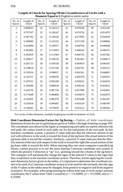
The next step is to transfer the revised basic dimension to the coordinate dimensioningsystem. To transfer the 2.126 dimension, the distance of the applicable holes from the leftreference axis must be determined. The first holes to the right are 0.8750 from the refer-ence axis. The second hole is 2.126 to the right of the first holes. Therefore, the second holeis 0.8750 + 2.126 = 3.0010 to the right of the reference axis. This value is then the coordi-nate dimension for the second hole, while the 0.8750 value is the coordinate dimension ofthe first two, vertically aligned holes. This procedure is followed for all the holes to findtheir distances from the two reference axes. These values are given in Fig. 1C.
The final step is to transfer the tolerances. The 2.126 value in Fig. 1B has been replacedby the 0.8750 and 3.0010 values in Fig. 1C. The 2.126 value has an available tolerance of±0.002. Dividing this amount equally between the two replacement values gives 0.8750 ±0.001 and 3.0010 ± 0.001. The sum of these tolerances is .002, and as required, does notexceed the tolerance that was replaced. Next transfer the tolerance of the 0.502 dimension.Divide the available tolerance, ±0.002, equally between the two replacement values toyield 3.0010 ±0.001 and 3.5030 ±0.001. The sum of these two tolerances equals thereplaced tolerance, as required. However, the 1.125 value of the last hole to the right (coor-dinate dimension 4.6280 in.) has a tolerance of only ±0.001. Therefore, the sum of the tol-erances on the 3.5030 and 4.6280 values cannot be larger than 0.001. Dividing thistolerance equally would give 3.5030 ± .0005 and 4.6280 ±0.0005. This new, smaller toler-ance replaces the ± 0.001 tolerance on the 3.5030 value in order to satisfy all tolerance sumrequirements. This example shows how the tolerance of a coordinate value is affected bymore than one other dimensional requirement.
954 JIG BORING
Fig. 1. (A) Conventional Dimensions, Mixed Tolerances; (B) Conventional Dimensions, All Equal, Bilateral Tolerances; and (C) Coordinate Dimensions
1.000
2.000
2.125 1.125
.500
.875
1.000±.005
±.005
±.001
+.003–.001
+.004–.000
±.005
1.000
2.000
2.126 1.125
A
B
.875
1.000±.005
±.005
±.001
±.002 ±.001
.502±.002
±.005
1.0002.000
C
1.000
Ref. Ref
.
±.0005
±.0005
3.000±.0045
.875
0±.00
10
±.001
3.00
10±.00
10
3.50
30±.00
05
4.62
80±.00
05
JIG BORING 955
The following discussion will summarize the various tolerances listed in Fig. 1C. For the0.8750 ± 0.0010 dimension, the ± 0.0010 tolerance together with the ± 0.0010 tolerance onthe 3.0010 dimension is required to maintain the ± 0.002 tolerance of the 2.126 dimension.The ± .0005 tolerances on the 3.5030 and 4.2680 dimensions are required to maintain the ±0.001 tolerance of the 1.125 dimension, at the same time as the sum of the ± .0005 toleranceon the 3.5030 dimension and the ± 0.001 tolerance on the 3.0010 dimension does notexceed the ± 0.002 tolerance on the replaced 0.503 dimension. The ± 0.0005 tolerances onthe 1.0000 and 2.0000 values maintain the ± 0.001 tolerance on the 1.0000 value given atthe right in Fig. 1A. The ± 0.0045 tolerance on the 3.0000 dimension together with the ±0.0005 tolerance on the 1.0000 value maintains the ± .005 tolerance on the 2.0000 dimen-sion of Fig. 1A. It should be noted that the 2.000 ± .005 dimension in Fig. 1A was replacedby the 1.0000 and 3.0000 dimensions in Fig. 1C. Each of these values could have had a tol-erance of ± 0.0025, except that the tolerance on the 1.0000 dimension on the left in Fig. 1Ais also bound by the ± 0.001 tolerance on the 1.0000 dimension on the right, thus the ±0.0005 tolerance value is used. This procedure requires the tolerance on the 3.0000 valueto be increased to ± 0.0045.
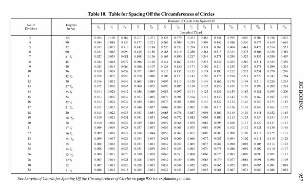
Lengths of Chords for Spacing Off the Circumferences of Circles
On the following pages are given tables of the lengths of chords for spacing off the cir-cumferences of circles. The object of these tables is to make possible the division of theperiphery into a number of equal parts without trials with the dividers. The first table is cal-culated for circles having a diameter equal to 1. For circles of other diameters, the length ofchord given in the table should be multiplied by the diameter of the circle. This first tablemay be used by toolmakers when setting “buttons” in circular formation. Assume that it isrequired to divide the periphery of a circle of 20 inches diameter into thirty-two equal parts.From the table the length of the chord is found to be 0.098017 inch, if the diameter of thecircle were 1 inch. With a diameter of 20 inches the length of the chord for one divisionwould be 20 × 0.098017 = 1.9603 inches. Another example in metric units: For a 100 mil-limeter diameter requiring 5 equal divisions, the length of the chord for one division wouldbe 100 × 0.587785 = 58.7785 millimeters.
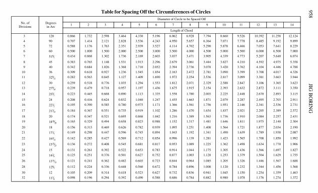
The two following pages give an additional table for the spacing off of circles, the table,in this case, being worked out for diameters from 1⁄16 inch to 14 inches. As an example,assume that it is required to divide a circle having a diameter of 61⁄2 inches into seven equalparts. Find first, in the column headed “6” and in line with 7 divisions, the length of thechord for a 6-inch circle, which is 2.603 inches. Then find the length of the chord for a 1⁄2-inch diameter circle, 7 divisions, which is 0.217. The sum of these two values, 2.603 +0.217 = 2.820 inches, is the length of the chord required for spacing off the circumferenceof a 61⁄2-inch circle into seven equal divisions.
As another example, assume that it is required to divide a circle having a diameter of 923⁄32inches into 15 equal divisions. First find the length of the chord for a 9-inch circle, which is1.871 inch. The length of the chord for a 23⁄32-inch circle can easily be estimated from thetable by taking the value that is exactly between those given for 11⁄16 and 3⁄4 inch. The valuefor 11⁄16 inch is 0.143, and for 3⁄4 inch, 0.156. For 23⁄32, the value would be 0.150. Then, 1.871+ 0.150 = 2.021 inches.
956 JIG BORING
Lengths of Chords for Spacing Off the Circumferences of Circles with a Diameter Equal to 1 (English or metric units)
For circles of other diameters, multiply length given in table by diameter of circle.
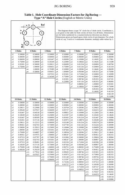
Hole Coordinate Dimension Factors for Jig Boring.—Tables of hole coordinatedimension factors for use in jig boring are given in Tables 1 through 4 starting on page959.The coordinate axes shown in the figure accompanying each table are used to reference thetool path; the values listed in each table are for the end points of the tool path. In thismachine coordinate system, a positive Y value indicates that the effective motion of thetool with reference to the work is toward the front of the jig borer (the actual motion of thejig borer table is toward the column). Similarly, a positive X value indicates that the effec-tive motion of the tool with respect to the work is toward the right (the actual motion of thejig borer table is toward the left). When entering data into most computer-controlled jigborers, current practice is to use the more familiar Cartesian coordinate axis system inwhich the positive Y direction is “up” (i.e., pointing toward the column of the jig borer).The computer will automatically change the signs of the entered Y values to the signs thatthey would have in the machine coordinate system. Therefore, before applying the coordi-nate dimension factors given in the tables, it is important to determine the coordinate sys-tem to be used. If a Cartesian coordinate system is to be used for the tool path, then the signof the Y values in the tables must be changed, from positive to negative and from negativeto positive. For example, when programming for a three-hole type A circle using Cartesiancoordinates, the Y values from Table 3 would be y1 = + 0.50000, y2 = −0.25000, and y3 =−0.25000.
No. ofSpaces
Length ofChord
No. ofSpaces
Length ofChord
No. ofSpaces
Length ofChord
No. ofSpaces
Length ofChord
3 0.866025 22 0.142315 41 0.076549 60 0.052336
4 0.707107 23 0.136167 42 0.074730 61 0.051479
5 0.587785 24 0.130526 43 0.072995 62 0.050649
6 0.500000 25 0.125333 44 0.071339 63 0.049846
7 0.433884 26 0.120537 45 0.069756 64 0.049068
8 0.382683 27 0.116093 46 0.068242 65 0.048313
9 0.342020 28 0.111964 47 0.066793 66 0.047582
10 0.309017 29 0.108119 48 0.065403 67 0.046872
11 0.281733 30 0.104528 49 0.064070 68 0.046183
12 0.258819 31 0.101168 50 0.062791 69 0.045515
13 0.239316 32 0.098017 51 0.061561 70 0.044865
14 0.222521 33 0.095056 52 0.060378 71 0.044233
15 0.207912 34 0.092268 53 0.059241 72 0.043619
16 0.195090 35 0.089639 54 0.058145 73 0.043022
17 0.183750 36 0.087156 55 0.057089 74 0.042441
18 0.173648 37 0.084806 56 0.056070 75 0.041876
19 0.164595 38 0.082579 57 0.055088 76 0.041325
20 0.156434 39 0.080467 58 0.054139 77 0.040789
21 0.149042 40 0.078459 59 0.053222 78 0.040266
JIG B
OR
ING
957See Lengths of Chords for Spacing Off the Circumferences of Circles on page 955 for explanatory matter.
Table 10. Table for Spacing Off the Circumferences of Circles
No. ofDivisions
Degreesin Arc
Diameter of Circle to be Spaced Off
1⁄161⁄8 3⁄16
1⁄4 5⁄163⁄8 7⁄16
1⁄2 9⁄165⁄8 11⁄16
3⁄4 13⁄167⁄8 15⁄16
Length of Chord
3 120 0.054 0.108 0.162 0.217 0.271 0.325 0.379 0.433 0.487 0.541 0.595 0.650 0.704 0.758 0.812
4 90 0.044 0.088 0.133 0.177 0.221 0.265 0.309 0.354 0.398 0.442 0.486 0.530 0.575 0.619 0.663
5 72 0.037 0.073 0.110 0.147 0.184 0.220 0.257 0.294 0.331 0.367 0.404 0.441 0.478 0.514 0.551
6 60 0.031 0.063 0.094 0.125 0.156 0.188 0.219 0.250 0.281 0.313 0.344 0.375 0.406 0.438 0.469
7 51 3⁄7 0.027 0.054 0.081 0.108 0.136 0.163 0.190 0.217 0.244 0.271 0.298 0.325 0.353 0.380 0.407
8 45 0.024 0.048 0.072 0.096 0.120 0.144 0.167 0.191 0.215 0.239 0.263 0.287 0.311 0.335 0.359
9 40 0.021 0.043 0.064 0.086 0.107 0.128 0.150 0.171 0.192 0.214 0.235 0.257 0.278 0.299 0.321
10 36 0.019 0.039 0.058 0.077 0.097 0.116 0.135 0.155 0.174 0.193 0.212 0.232 0.251 0.270 0.290
11 32 8⁄11 0.018 0.035 0.053 0.070 0.088 0.106 0.123 0.141 0.158 0.176 0.194 0.211 0.229 0.247 0.264
12 30 0.016 0.032 0.049 0.065 0.081 0.097 0.113 0.129 0.146 0.162 0.178 0.194 0.210 0.226 0.243
13 27 9⁄13 0.015 0.030 0.045 0.060 0.075 0.090 0.105 0.120 0.135 0.150 0.165 0.179 0.194 0.209 0.224
14 25 5⁄7 0.014 0.028 0.042 0.056 0.069 0.083 0.097 0.111 0.125 0.139 0.153 0.167 0.181 0.195 0.209
15 24 0.013 0.026 0.039 0.052 0.065 0.078 0.091 0.104 0.117 0.130 0.143 0.156 0.169 0.182 0.195
16 22 1⁄2 0.012 0.024 0.037 0.049 0.061 0.073 0.085 0.098 0.110 0.122 0.134 0.146 0.159 0.171 0.183
17 21 3⁄17 0.011 0.023 0.034 0.046 0.057 0.069 0.080 0.092 0.103 0.115 0.126 0.138 0.149 0.161 0.172
18 20 0.011 0.022 0.033 0.043 0.054 0.065 0.076 0.087 0.098 0.109 0.119 0.130 0.141 0.152 0.163
19 18 18⁄19 0.010 0.021 0.031 0.041 0.051 0.062 0.072 0.082 0.093 0.103 0.113 0.123 0.134 0.144 0.154
20 18 0.010 0.020 0.029 0.039 0.049 0.059 0.068 0.078 0.088 0.098 0.108 0.117 0.127 0.137 0.147
21 17 1⁄7 0.009 0.019 0.028 0.037 0.047 0.056 0.065 0.075 0.084 0.093 0.102 0.112 0.121 0.130 0.140
22 16 4⁄11 0.009 0.018 0.027 0.036 0.044 0.053 0.062 0.071 0.080 0.089 0.098 0.107 0.116 0.125 0.133
23 15 15⁄23 0.009 0.017 0.026 0.034 0.043 0.051 0.060 0.068 0.077 0.085 0.094 0.102 0.111 0.119 0.128
24 15 0.008 0.016 0.024 0.033 0.041 0.049 0.057 0.065 0.073 0.082 0.090 0.098 0.106 0.114 0.122
25 14 2⁄5 0.008 0.016 0.023 0.031 0.039 0.047 0.055 0.063 0.070 0.078 0.086 0.094 0.102 0.110 0.117
26 13 11⁄13 0.008 0.015 0.023 0.030 0.038 0.045 0.053 0.060 0.068 0.075 0.083 0.090 0.098 0.105 0.113
28 12 6⁄7 0.007 0.014 0.021 0.028 0.035 0.042 0.049 0.056 0.063 0.070 0.077 0.084 0.091 0.098 0.105
30 12 0.007 0.013 0.020 0.026 0.033 0.039 0.046 0.052 0.059 0.065 0.072 0.078 0.085 0.091 0.098
32 11 1⁄4 0.006 0.012 0.018 0.025 0.031 0.037 0.043 0.049 0.055 0.061 0.067 0.074 0.080 0.086 0.092
JIG B
OR
ING
958Table for Spacing Off the Circumferences of Circles
No. ofDivisions
Degreesin Arc
Diameter of Circle to be Spaced Off
1 2 3 4 5 6 7 8 9 10 11 12 13 14
Length of Chord
3 120 0.866 1.732 2.598 3.464 4.330 5.196 6.062 6.928 7.794 8.660 9.526 10.392 11.258 12.124
4 90 0.707 1.414 2.121 2.828 3.536 4.243 4.950 5.657 6.364 7.071 7.778 8.485 9.192 9.899
5 72 0.588 1.176 1.763 2.351 2.939 3.527 4.114 4.702 5.290 5.878 6.466 7.053 7.641 8.229
6 60 0.500 1.000 1.500 2.000 2.500 3.000 3.500 4.000 4.500 5.000 5.500 6.000 6.500 7.000
7 518⁄7 0.434 0.868 1.302 1.736 2.169 2.603 3.037 3.471 3.905 4.339 4.773 5.207 5.640 6.074
8 45 0.383 0.765 1.148 1.531 1.913 2.296 2.679 3.061 3.444 3.827 4.210 4.592 4.975 5.358
9 40 0.342 0.684 1.026 1.368 1.710 2.052 2.394 2.736 3.078 3.420 3.762 4.104 4.446 4.788
10 36 0.309 0.618 0.927 1.236 1.545 1.854 2.163 2.472 2.781 3.090 3.399 3.708 4.017 4.326
11 328⁄11 0.282 0.563 0.845 1.127 1.409 1.690 1.972 2.254 2.536 2.817 3.099 3.381 3.663 3.944
12 30 0.259 0.518 0.776 1.035 1.294 1.553 1.812 2.071 2.329 2.588 2.847 3.106 3.365 3.623
13 279⁄13 0.239 0.479 0.718 0.957 1.197 1.436 1.675 1.915 2.154 2.393 2.632 2.872 3.111 3.350
14 255⁄7 0.223 0.445 0.668 0.890 1.113 1.335 1.558 1.780 2.003 2.225 2.448 2.670 2.893 3.115
15 24 0.208 0.416 0.624 0.832 1.040 1.247 1.455 1.663 1.871 2.079 2.287 2.495 2.703 2.911
16 221⁄2 0.195 0.390 0.585 0.780 0.975 1.171 1.366 1.561 1.756 1.951 2.146 2.341 2.536 2.731
17 213⁄17 0.184 0.367 0.551 0.735 0.919 1.102 1.286 1.470 1.654 1.837 2.021 2.205 2.389 2.572
18 20 0.174 0.347 0.521 0.695 0.868 1.042 1.216 1.389 1.563 1.736 1.910 2.084 2.257 2.431
19 1818⁄19 0.165 0.329 0.494 0.658 0.823 0.988 1.152 1.317 1.481 1.646 1.811 1.975 2.140 2.304
20 18 0.156 0.313 0.469 0.626 0.782 0.939 1.095 1.251 1.408 1.564 1.721 1.877 2.034 2.190
21 171⁄7 0.149 0.298 0.447 0.596 0.745 0.894 1.043 1.192 1.341 1.490 1.639 1.789 1.938 2.087
22 164⁄11 0.142 0.285 0.427 0.569 0.712 0.854 0.996 1.139 1.281 1.423 1.565 1.708 1.850 1.992
23 1515⁄23 0.136 0.272 0.408 0.545 0.681 0.817 0.953 1.089 1.225 1.362 1.498 1.634 1.770 1.906
24 15 0.131 0.261 0.392 0.522 0.653 0.783 0.914 1.044 1.175 1.305 1.436 1.566 1.697 1.827
25 142⁄5 0.125 0.251 0.376 0.501 0.627 0.752 0.877 1.003 1.128 1.253 1.379 1.504 1.629 1.755
26 1311⁄13 0.121 0.241 0.362 0.482 0.603 0.723 0.844 0.964 1.085 1.205 1.326 1.446 1.567 1.688
28 126⁄7 0.112 0.224 0.336 0.448 0.560 0.672 0.784 0.896 1.008 1.120 1.232 1.344 1.456 1.568
30 12 0.105 0.209 0.314 0.418 0.523 0.627 0.732 0.836 0.941 1.045 1.150 1.254 1.359 1.463
32 111⁄4 0.098 0.196 0.294 0.392 0.490 0.588 0.686 0.784 0.882 0.980 1.078 1.176 1.274 1.372
JIG BORING 959
Table 1. Hole Coordinate Dimension Factors for Jig Boring — Type “A” Hole Circles (English or Metric Units)
The diagram shows a type “A” circle for a 5-hole circle. Coordinates x, y are given in the table for hole circles of from 3 to 28 holes. Dimensions are for holes numbered in a counterclockwise direction (as shown). Dimensions given are based upon a hole circle of unit diameter. For a hole circle of, say, 3-inch or 3-centimeter diameter, multiply table values by 3.
3 Holes 4 Holes 5 Holes 6 Holes 7 Holes 8 Holes 9 Holes
x1 0.50000 x1 0.50000 x1 0.50000 x1 0.50000 x1 0.50000 x1 0.50000 x1 0.50000y1 0.00000 y1 0.00000 y1 0.00000 y1 0.00000 y1 0.00000 y1 0.00000 y1 0.00000x2 0.06699 x2 0.00000 x2 0.02447 x2 0.06699 x2 0.10908 x2 0.14645 x2 0.17861y2 0.75000 y2 0.50000 y2 0.34549 y2 0.25000 y2 0.18826 y2 0.14645 y2 0.11698x3 0.93301 x3 0.50000 x3 0.20611 x3 0.06699 x3 0.01254 x3 0.00000 x3 0.00760y3 0.75000 y3 1.00000 y3 0.90451 y3 0.75000 y3 0.61126 y3 0.50000 y3 0.41318
x4 1.00000 x4 0.79389 x4 0.50000 x4 0.28306 x4 0.14645 x4 0.06699y4 0.50000 y4 0.90451 y4 1.00000 y4 0.95048 y4 0.85355 y4 0.75000
x5 0.97553 x5 0.93301 x5 0.71694 x5 0.50000 x5 0.32899y5 0.34549 y5 0.75000 y5 0.95048 y5 1.00000 y5 0.96985
x6 0.93301 x6 0.98746 x6 0.85355 x6 0.67101y6 0.25000 y6 0.61126 y6 0.85355 y6 0.96985
x7 0.89092 x7 1.00000 x7 0.93301y7 0.18826 y7 0.50000 y7 0.75000
x8 0.85355 x8 0.99240y8 0.14645 y8 0.41318
x9 0.82139y9 0.11698
10 Holes 11 Holes 12 Holes 13 Holes 14 Holes 15 Holes 16 Holes
x1 0.50000 x1 0.50000 x1 0.50000 x1 0.50000 x1 0.50000 x1 0.50000 x1 0.50000y1 0.00000 y1 0.00000 y1 0.00000 y1 0.00000 y1 0.00000 y1 0.00000 y1 0.00000x2 0.20611 x2 0.22968 x2 0.25000 x2 0.26764 x2 0.28306 x2 0.29663 x2 0.30866y2 0.09549 y2 0.07937 y2 0.06699 y2 0.05727 y2 0.04952 y2 0.04323 y2 0.03806x3 0.02447 x3 0.04518 x3 0.06699 x3 0.08851 x3 0.10908 x3 0.12843 x3 0.14645y3 0.34549 y3 0.29229 y3 0.25000 y3 0.21597 y3 0.18826 y3 0.16543 y3 0.14645x4 0.02447 x4 0.00509 x4 0.00000 x4 0.00365 x4 0.01254 x4 0.02447 x4 0.03806y4 0.65451 y4 0.57116 y4 0.50000 y4 0.43973 y4 0.38874 y4 0.34549 y4 0.30866x5 0.20611 x5 0.12213 x5 0.06699 x5 0.03249 x5 0.01254 x5 0.00274 x5 0.00000y5 0.90451 y5 0.82743 y5 0.75000 y5 0.67730 y5 0.61126 y5 0.55226 y5 0.50000x6 0.50000 x6 0.35913 x6 0.25000 x6 0.16844 x6 0.10908 x6 0.06699 x6 0.03806y6 1.00000 y6 0.97975 y6 0.93301 y6 0.87426 y6 0.81174 y6 0.75000 y6 0.69134x7 0.79389 x7 0.64087 x7 0.50000 x7 0.38034 x7 0.28306 x7 0.20611 x7 0.14645y7 0.90451 y7 0.97975 y7 1.00000 y7 0.98547 y7 0.95048 y7 0.90451 y7 0.85355x8 0.97553 x8 0.87787 x8 0.75000 x8 0.61966 x8 0.50000 x8 0.39604 x8 0.30866y8 0.65451 y8 0.82743 y8 0.93301 y8 0.98547 y8 1.00000 y8 0.98907 y8 0.96194x9 0.97553 x9 0.99491 x9 0.93301 x9 0.83156 x9 0.71694 x9 0.60396 x9 0.50000y9 0.34549 y9 0.57116 y9 0.75000 y9 0.87426 y9 0.95048 y9 0.98907 y9 1.00000x10 0.79389 x10 0.95482 x10 1.00000 x10 0.96751 x10 0.89092 x10 0.79389 x10 0.69134y10 0.09549 y10 0.29229 y10 0.50000 y10 0.67730 y10 0.81174 y10 0.90451 y10 0.96194
x11 0.77032 x11 0.93801 x11 0.99635 x11 0.98746 x11 0.93301 x11 0.85355y11 0.07937 y11 0.25000 y11 0.43973 y11 0.61126 y11 0.75000 y11 0.85355
x12 0.75000 x12 0.91149 x12 0.98746 x12 0.99726 x12 0.96194y12 0.06699 y12 0.21597 y12 0.38874 y12 0.55226 y12 0.69134
x13 0.73236 x13 0.89092 x13 0.97553 x13 1.00000y13 0.05727 y13 0.18826 y13 0.34549 y13 0.50000
x14 0.71694 x14 0.87157 x14 0.96194y14 0.04952 y14 0.16543 y14 0.30866
x15 0.70337 x15 0.85355y15 0.04323 y15 0.14645
x16 0.69134y16 0.03806
960 JIG BORING
17 Holes 18 Holes 19 Holes 20 Holes 21 Holes 22 Holes 23 Holes
x1 0.50000 x1 0.50000 x1 0.50000 x1 0.50000 x1 0.50000 x1 0.50000 x1 0.50000y1 0.00000 y1 0.00000 y1 0.00000 y1 0.00000 y1 0.00000 y1 0.00000 y1 0.00000x2 0.31938 x2 0.32899 x2 0.33765 x2 0.34549 x2 0.35262 x2 0.35913 x2 0.36510y2 0.03376 y2 0.03015 y2 0.02709 y2 0.02447 y2 0.02221 y2 0.02025 y2 0.01854x3 0.16315 x3 0.17861 x3 0.19289 x3 0.20611 x3 0.21834 x3 0.22968 x3 0.24021y3 0.13050 y3 0.11698 y3 0.10543 y3 0.09549 y3 0.08688 y3 0.07937 y3 0.07279x4 0.05242 x4 0.06699 x4 0.08142 x4 0.09549 x4 0.10908 x4 0.12213 x4 0.13458y4 0.27713 y4 0.25000 y4 0.22653 y4 0.20611 y4 0.18826 y4 0.17257 y4 0.15872x5 0.00213 x5 0.00760 x5 0.01530 x5 0.02447 x5 0.03456 x5 0.04518 x5 0.05606y5 0.45387 y5 0.41318 y5 0.37726 y5 0.34549 y5 0.31733 y5 0.29229 y5 0.26997x6 0.01909 x6 0.00760 x6 0.00171 x6 0.00000 x6 0.00140 x6 0.00509 x6 0.01046y6 0.63683 y6 0.58682 y6 0.54129 y6 0.50000 y6 0.46263 y6 0.42884 y6 0.39827x7 0.10099 x7 0.06699 x7 0.04211 x7 0.02447 x7 0.01254 x7 0.00509 x7 0.00117y7 0.80132 y7 0.75000 y7 0.70085 y7 0.65451 y7 0.61126 y7 0.57116 y7 0.53412x8 0.23678 x8 0.17861 x8 0.13214 x8 0.09549 x8 0.06699 x8 0.04518 x8 0.02887y8 0.92511 y8 0.88302 y8 0.83864 y8 0.79389 y8 0.75000 y8 0.70771 y8 0.66744x9 0.40813 x9 0.32899 x9 0.26203 x9 0.20611 x9 0.15991 x9 0.12213 x9 0.09152y9 0.99149 y9 0.96985 y9 0.93974 y9 0.90451 y9 0.86653 y9 0.82743 y9 0.78834x10 0.59187 x10 0.50000 x10 0.41770 x10 0.34549 x10 0.28306 x10 0.22968 x10 0.18446y10 0.99149 y10 1.00000 y10 0.99318 y10 0.97553 y10 0.95048 y10 0.92063 y10 0.88786x11 0.76322 x11 0.67101 x11 0.58230 x11 0.50000 x11 0.42548 x11 0.35913 x11 0.30080y11 0.92511 y11 0.96985 y11 0.99318 y11 1.00000 y11 0.99442 y11 0.97975 y11 0.95861x12 0.89901 x12 0.82139 x12 0.73797 x12 0.65451 x12 0.57452 x12 0.50000 x12 0.43192y12 0.80132 y12 0.88302 y12 0.93974 y12 0.97553 y12 0.99442 y12 1.00000 y12 0.99534x13 0.98091 x13 0.93301 x13 0.86786 x13 0.79389 x13 0.71694 x13 0.64087 x13 0.56808y13 0.63683 y13 0.75000 y13 0.83864 y13 0.90451 y13 0.95048 y13 0.97975 y13 0.99534x14 0.99787 x14 0.99240 x14 0.95789 x14 0.90451 x14 0.84009 x14 0.77032 x14 0.69920y14 0.45387 y14 0.58682 y14 0.70085 y14 0.79389 y14 0.86653 y14 0.92063 y14 0.95861x15 0.94758 x15 0.99240 x15 0.99829 x15 0.97553 x15 0.93301 x15 0.87787 x15 0.81554y15 0.27713 y15 0.41318 y15 0.54129 y15 0.65451 y15 0.75000 y15 0.82743 y15 0.88786x16 0.83685 x16 0.93301 x16 0.98470 x16 1.00000 x16 0.98746 x16 0.95482 x16 0.90848y16 0.13050 y16 0.25000 y16 0.37726 y16 0.50000 y16 0.61126 y16 0.70771 y16 0.78834x17 0.68062 x17 0.82139 x17 0.91858 x17 0.97553 x17 0.99860 x17 0.99491 x17 0.97113y17 0.03376 y17 0.11698 y17 0.22658 y17 0.34549 y17 0.46263 y17 0.57116 y17 0.66744
x18 0.67101 x18 0.80711 x18 0.90451 x18 0.96544 x18 0.99491 x18 0.99883y18 0.03015 y18 0.10543 y18 0.20611 y18 0.31733 y18 0.42884 y18 0.53412
x19 0.66235 x19 0.79389 x19 0.89092 x19 0.95482 x19 0.98954y19 0.02709 y19 0.09549 y19 0.18826 y19 0.29229 y19 0.39827
x20 0.65451 x20 0.78166 x20 0.87787 x20 0.94394y20 0.02447 y20 0.08688 y20 0.17257 y20 0.26997
x21 0.64738 x21 0.77032 x21 0.86542y21 0.02221 y21 0.07937 y21 0.15872
x22 0.64087 x22 0.75979y22 0.02025 y22 0.07279
x23 0.63490y23 0.01854
24Holes 25 Holes 26 Holes 27 Holes 28 Holes
x1 0.50000 x1 0.50000 x1 0.50000 x1 0.50000 x1 0.50000y1 0.00000 y1 0.00000 y1 0.00000 y1 0.00000 y1 0.00000x2 0.37059 x2 0.37566 x2 0.38034 x2 0.38469 x2 0.38874y2 0.01704 y2 0.01571 y2 0.01453 y2 0.01348 y2 0.01254x3 0.25000 x3 0.25912 x3 0.26764 x3 0.27560 x3 0.28306
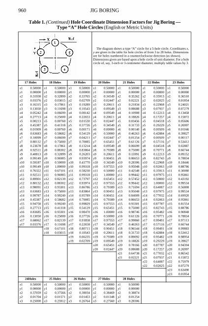
Table 1. (Continued) Hole Coordinate Dimension Factors for Jig Boring — Type “A” Hole Circles (English or Metric Units)
The diagram shows a type “A” circle for a 5-hole circle. Coordinates x, y are given in the table for hole circles of from 3 to 28 holes. Dimensions are for holes numbered in a counterclockwise direction (as shown). Dimensions given are based upon a hole circle of unit diameter. For a hole circle of, say, 3-inch or 3-centimeter diameter, multiply table values by 3.
JIG BORING 961
y3 0.06699 y3 0.06185 y3 0.05727 y3 0.05318 y3 0.04952x4 0.14645 x4 0.15773 x4 0.16844 x4 0.17861 x4 0.18826y4 0.14645 y4 0.13552 y4 0.12574 y4 0.11698 y4 0.10908x5 0.06699 x5 0.07784 x5 0.08851 x5 0.09894 x5 0.10908y5 0.25000 y5 0.23209 y5 0.21597 y5 0.20142 y5 0.18826x6 0.01704 x6 0.02447 x6 0.03249 x6 0.04089 x6 0.04952y6 0.37059 y6 0.34549 y6 0.32270 y6 0.30196 y6 0.28306x7 0.00000 x7 0.00099 x7 0.00365 x7 0.00760 x7 0.01254y7 0.50000 y7 0.46860 y7 0.43973 y7 0.41318 y7 0.38874x8 0.01704 x8 0.00886 x8 0.00365 x8 0.00085 x8 0.00000y8 0.62941 y8 0.59369 y8 0.56027 y8 0.52907 y8 0.50000x9 0.06699 x9 0.04759 x9 0.03249 x9 0.02101 x9 0.01254y9 0.75000 y9 0.71289 y9 0.67730 y9 0.64340 y9 0.61126x10 0.14645 x10 0.11474 x10 0.08851 x10 0.06699 x10 0.04952y10 0.85355 y10 0.81871 y10 0.78403 y10 0.75000 y10 0.71694x11 0.25000 x11 0.20611 x11 0.16844 x11 0.13631 x11 0.10908y11 0.93301 y11 0.90451 y11 0.87426 y11 0.84312 y11 0.81174x12 0.37059 x12 0.31594 x12 0.26764 x12 0.22525 x12 0.18826y12 0.98296 y12 0.96489 y12 0.94273 y12 0.91774 y12 0.89092x13 0.50000 x13 0.43733 x13 0.38034 x13 0.32899 x13 0.28306y13 1.00000 y13 0.99606 y13 0.98547 y13 0.96985 y13 0.95048x14 0.62941 x14 0.56267 x14 0.50000 x14 0.44195 x14 0.38874y14 0.98296 y14 0.99606 y14 1.00000 y14 0.99662 y14 0.98746x15 0.75000 x15 0.68406 x15 0.61966 x15 0.55805 x15 0.50000y15 0.93301 y15 0.96489 y15 0.98547 y15 0.99662 y15 1.00000x16 0.85355 x16 0.79389 x16 0.73236 x16 0.67101 x16 0.61126y16 0.85355 y16 0.90451 y16 0.94273 y16 0.96985 y16 0.98746x17 0.93301 x17 0.88526 x17 0.83156 x17 0.77475 x17 0.71694y17 0.75000 y17 0.81871 y17 0.87426 y17 0.91774 y17 0.95048x18 0.98296 x18 0.95241 x18 0.91149 x18 0.86369 x18 0.81174y18 0.62941 y18 0.71289 y18 0.78403 y18 0.84312 y18 0.89092x19 1.00000 x19 0.99114 x19 0.96751 x19 0.93301 x19 0.89092y19 0.50000 y19 0.59369 y19 0.67730 y19 0.75000 y19 0.81174x20 0.98296 x20 0.99901 x20 0.99635 x20 0.97899 x20 0.95048y20 0.37059 y20 0.46860 y20 0.56027 y20 0.64340 y20 0.71694x21 0.93301 x21 0.97553 x21 0.99635 x21 0.99915 x21 0.98746y21 0.25000 y21 0.34549 y21 0.43973 y21 0.52907 y21 0.61126x22 0.85355 x22 0.92216 x22 0.96751 x22 0.99240 x22 1.00000y22 0.14645 y22 0.23209 y22 0.32270 y22 0.41318 y22 0.50000x23 0.75000 x23 0.84227 x23 0.91149 x23 0.95911 x23 0.98746y23 0.6699 y23 0.13552 y23 0.21597 y23 0.30196 y23 0.38874x24 0.62941 x24 0.74088 x24 0.83156 x24 0.90106 x24 0.95048y24 0.01704 y24 0.06185 y24 0.12574 y24 0.20142 y24 0.28306
x25 0.62434 x25 0.73236 x25 0.82139 x25 0.89092y25 0.01571 y25 0.05727 y25 0.11698 y25 0.18826
x26 0.61966 x26 0.72440 x26 0.81174y26 0.01453 y26 0.05318 y26 0.10908
x27 0.61531 x27 0.71694y27 0.01348 y27 0.04952
x28 0.61126y28 0.01254
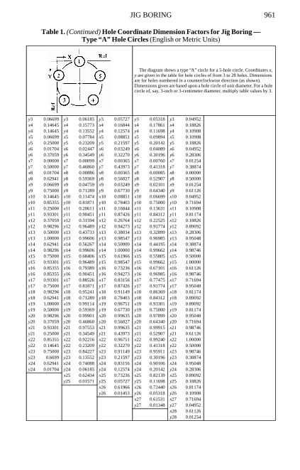
Table 1. (Continued) Hole Coordinate Dimension Factors for Jig Boring — Type “A” Hole Circles (English or Metric Units)
The diagram shows a type “A” circle for a 5-hole circle. Coordinates x, y are given in the table for hole circles of from 3 to 28 holes. Dimensions are for holes numbered in a counterclockwise direction (as shown). Dimensions given are based upon a hole circle of unit diameter. For a hole circle of, say, 3-inch or 3-centimeter diameter, multiply table values by 3.
962 JIG BORING
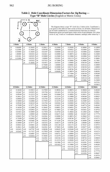
Table 2. Hole Coordinate Dimension Factors for Jig Boring — Type “B” Hole Circles (English or Metric Units)
The diagram shows a type “B” circle for a 5-hole circle. Coordinates x, y are given in the table for hole circles of from 3 to 28 holes. Dimensions are for holes numbered in a counterclockwise direction (as shown). Dimensions given are based upon a hole circle of unit diameter. For a hole circle of, say, 3-inch or 3-centimeter diameter, multiply table values by 3.
3 Holes 4 Holes 5 Holes 6 Holes 7 Holes 8 Holes 9 Holes
x1 0.06699 x1 0.14645 x1 0.20611 x1 0.25000 x1 0.28306 x1 0.30866 x1 0.32899y1 0.25000 y1 0.14645 y1 0.09549 y1 0.06699 y1 0.04952 y1 0.03806 y1 0.03015x2 0.50000 x2 0.14645 x2 0.02447 x2 0.00000 x2 0.01254 x2 0.03806 x2 0.06699y2 1.00000 y2 0.85355 y2 0.65451 y2 0.50000 y2 0.38874 y2 0.30866 y2 0.25000x3 0.93301 x3 0.85355 x3 0.50000 x3 0.25000 x3 0.10908 x3 0.03806 x3 0.00760y3 0.25000 y3 0.85355 y3 1.00000 y3 0.93301 y3 0.81174 y3 0.69134 y3 0.58682
x4 0.85355 x4 0.97553 x4 0.75000 x4 0.50000 x4 0.30866 x4 0.17861y4 0.14645 y4 0.65451 y4 0.93301 y4 1.00000 y4 0.96194 y4 0.88302
x5 0.79389 x5 1.00000 x5 0.89092 x5 0.69134 x5 0.50000y5 0.09549 y5 0.50000 y5 0.81174 y5 0.96194 y5 1.00000
x6 0.75000 x6 0.98746 x6 0.96194 x6 0.82139y6 0.06699 y6 0.38874 y6 0.69134 y6 0.88302
x7 0.71694 x7 0.96194 x7 0.99240y7 0.04952 y7 0.30866 y7 0.58682
x8 0.69134 x8 0.93301y8 0.03806 y8 0.25000
x9 0.67101y9 0.03015
10 Holes 11 Holes 12 Holes 13 Holes 14 Holes 15 Holes 16 Holes
x1 0.34549 x1 0.35913 x1 0.37059 x1 0.38034 x1 0.38874 x1 0.39604 x1 0.40245y1 0.02447 y1 0.02025 y1 0.01704 y1 0.01453 y1 0.01254 y1 0.01093 y1 0.00961x2 0.09549 x2 0.12213 x2 0.14645 x2 0.16844 x2 0.18826 x2 0.20611 x2 0.22221y2 0.20611 y2 0.17257 y2 0.14645 y2 0.12574 y2 0.10908 y2 0.09549 y2 0.08427x3 0.00000 x3 0.00509 x3 0.01704 x3 0.03249 x3 0.04952 x3 0.06699 x3 0.08427y3 0.50000 y3 0.42884 y3 0.37059 y3 0.32270 y3 0.28306 y3 0.25000 y3 0.22221x4 0.09549 x4 0.04518 x4 0.01704 x4 0.00365 x4 0.00000 x4 0.00274 x4 0.00961y4 0.79389 y4 0.70771 y4 0.62941 y4 0.56027 y4 0.50000 y4 0.44774 y4 0.40245x5 0.34549 x5 0.22968 x5 0.14645 x5 0.08851 x5 0.04952 x5 0.02447 x5 0.00961y5 0.97553 y5 0.92063 y5 0.85355 y5 0.78403 y5 0.71694 y5 0.65451 y5 0.59755x6 0.65451 x6 0.50000 x6 0.37059 x6 0.26764 x6 0.18826 x6 0.12843 x6 0.08427y6 0.97553 y6 1.00000 y6 0.98296 y6 0.94273 y6 0.89092 y6 0.83457 y6 0.77779x7 0.90451 x7 0.77032 x7 0.62941 x7 0.50000 x7 0.38874 x7 0.29663 x7 0.22221y7 0.79389 y7 0.92063 y7 0.98296 y7 1.00000 y7 0.98746 y7 0.95677 y7 0.91573x8 1.00000 x8 0.95482 x8 0.85355 x8 0.73236 x8 0.61126 x8 0.50000 x8 0.40245y8 0.50000 y8 0.70771 y8 0.85355 y8 0.94273 y8 0.98746 y8 1.00000 y8 0.99039x9 0.90451 x9 0.99491 x9 0.98296 x9 0.91149 x9 0.81174 x9 0.70337 x9 0.59755y9 0.20611 y9 0.42884 y9 0.62941 y9 0.78403 y9 0.89092 y9 0.95677 y9 0.99039x10 0.65451 x10 0.87787 x10 0.98296 x10 0.99635 x10 0.95048 x10 0.87157 x10 0.77779y10 0.02447 y10 0.17257 y10 0.37059 y10 0.56027 y10 0.71694 y10 0.83457 y10 0.91573
x11 0.64087 x11 0.85355 x11 0.96751 x11 1.00000 x11 0.97553 x11 0.91573y11 0.02025 y11 0.14645 y11 0.32270 y11 0.50000 y11 0.65451 y11 0.77779
x12 0.62941 x12 0.83156 x12 0.95048 x12 0.99726 x12 0.99039y12 0.01704 y12 0.12574 y12 0.28306 y12 0.44774 y12 0.59755
x13 0.61966 x13 0.81174 x13 0.93301 x13 0.99039y13 0.01453 y13 0.10908 y13 0.25000 y13 0.40245
x14 0.61126 x14 0.79389 x14 0.91573y14 0.01254 y14 0.09549 y14 0.22221
x15 0.60396 x15 0.77779y15 0.01093 y15 0.08427
x16 0.59755y16 0.00961
JIG BORING 963
17 Holes 18 Holes 19 Holes 20 Holes 21 Holes 22 Holes 23 Holes
x1 0.40813 x1 0.41318 x1 0.41770 x1 0.42178 x1 0.42548 x1 0.42884 x1 0.43192y1 0.00851 y1 0.00760 y1 0.00682 y1 0.00616 y1 0.00558 y1 0.00509 y1 0.00466x2 0.23678 x2 0.25000 x2 0.26203 x2 0.27300 x2 0.28306 x2 0.29229 x2 0.30080y2 0.07489 y2 0.06699 y2 0.06026 y2 0.05450 y2 0.04952 y2 0.04518 y2 0.04139x3 0.10099 x3 0.11698 x3 0.13214 x3 0.14645 x3 0.15991 x3 0.17257 x3 0.18446y3 0.19868 y3 0.17861 y3 0.16136 y3 0.14645 y3 0.13347 y3 0.12213 y3 0.11214x4 0.01909 x4 0.03015 x4 0.04211 x4 0.05450 x4 0.06699 x4 0.07937 x4 0.09152y4 0.36317 y4 0.32899 y4 0.29915 y4 0.27300 y4 0.25000 y4 0.22968 y4 0.21166x5 0.00213 x5 0.00000 x5 0.00171 x5 0.00616 x5 0.01254 x5 0.02025 x5 0.02887y5 0.54613 y5 0.50000 y5 0.45871 y5 0.42178 y5 0.38874 y5 0.35913 y5 0.33256x6 0.05242 x6 0.03015 x6 0.01530 x6 0.00616 x6 0.00140 x6 0.00000 x6 0.00117y6 0.72287 y6 0.67101 y6 0.62274 y6 0.57822 y6 0.53737 y6 0.50000 y6 0.46588x7 0.16315 x7 0.11698 x7 0.08142 x7 0.05450 x7 0.03456 x7 0.02025 x7 0.01046y7 0.86950 y7 0.82139 y7 0.77347 y7 0.72700 y7 0.68267 y7 0.64087 y7 0.60173x8 0.31938 x8 0.25000 x8 0.19289 x8 0.14645 x8 0.10908 x8 0.07937 x8 0.05606y8 0.96624 y8 0.93301 y8 0.89457 y8 0.85355 y8 0.81174 y8 0.77032 y8 0.73003x9 0.50000 x9 0.41318 x9 0.33765 x9 0.27300 x9 0.21834 x9 0.17257 x9 0.13458y9 1.00000 y9 0.99240 y9 0.97291 y9 0.94550 y9 0.91312 y9 0.87787 y9 0.84128x10 0.68062 x10 0.58682 x10 0.50000 x10 0.42178 x10 0.35262 x10 0.29229 x10 0.24021y10 0.96624 y10 0.99240 y10 1.00000 y10 0.99384 y10 0.97779 y10 0.95482 y10 0.92721x11 0.83685 x11 0.75000 x11 0.66235 x11 0.57822 x11 0.50000 x11 0.42884 x11 0.36510y11 0.86950 y11 0.93301 y11 0.97291 y11 0.99384 y11 1.00000 y11 0.99491 y11 0.98146x12 0.94758 x12 0.88302 x12 0.80711 x12 0.72700 x12 0.64738 x12 0.57116 x12 0.50000y12 0.72287 y12 0.82139 y12 0.89457 y12 0.94550 y12 0.97779 y12 0.99491 y12 1.00000x13 0.99787 x13 0.96985 x13 0.91858 x13 0.85355 x13 0.78166 x13 0.70771 x13 0.63490y13 0.54613 y13 0.67101 y13 0.77347 y13 0.85355 y13 0.91312 y13 0.95482 y13 0.98146x14 0.98091 x14 1.00000 x14 0.98470 x14 0.94550 x14 0.89092 x14 0.82743 x14 0.75979y14 0.36317 y14 0.50000 y14 0.62274 y14 0.72700 y14 0.81174 y14 0.87787 y14 0.92721x15 0.89901 x15 0.96985 x15 0.99829 x15 0.99384 x15 0.96544 x15 0.92063 x15 0.86542y15 0.19868 y15 0.32899 y15 0.45871 y15 0.57822 y15 0.68267 y15 0.77032 y15 0.84128x16 0.76322 x16 0.88302 x16 0.95789 x16 0.99384 x16 0.99860 x16 0.97975 x16 0.94394y16 0.07489 y16 0.17861 y16 0.29915 y16 0.42178 y16 0.53737 y16 0.64087 y16 0.73003x17 0.59187 x17 0.75000 x17 0.86786 x17 0.94550 x17 0.98746 x17 1.00000 x17 0.98954y17 0.00851 y17 0.06699 y17 0.16136 y17 0.27300 y17 0.38874 y17 0.50000 y17 0.60173
x18 0.58682 x18 0.73797 x18 0.85355 x18 0.93301 x18 0.97975 x18 0.99883y18 0.00760 y18 0.06026 y18 0.14645 y18 0.25000 y18 0.35913 y18 0.46588
x19 0.58230 x19 0.72700 x19 0.84009 x19 0.92063 x19 0.97113y19 0.00682 y19 0.05450 y19 0.13347 y19 0.22968 y19 0.33256
x20 0.57822 x20 0.71694 x20 0.82743 x20 0.90848y20 0.00616 y20 0.04952 y20 0.12213 y20 0.21166
x21 0.57452 x21 0.70771 x21 0.81554y21 0.00558 y21 0.04518 y21 0.11214
x22 0.57116 x22 0.69920y22 0.00509 y22 0.04139
x23 0.56808y23 0.00466
24 Holes 25 Holes 26 Holes 27 Holes 28 Holes
x1 0.43474 x1 0.43733 x1 0.43973 x1 0.44195 x1 0.44402y1 0.00428 y1 0.00394 y1 0.00365 y1 0.00338 y1 0.00314x2 0.30866 x2 0.31594 x2 0.32270 x2 0.32899 x2 0.33486y2 0.03806 y2 0.03511 y2 0.03249 y2 0.03015 y2 0.02806x3 0.19562 x3 0.20611 x3 0.21597 x3 0.22525 x3 0.23398
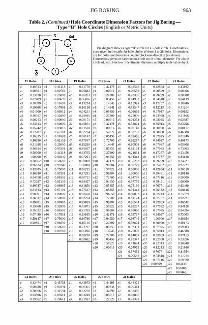
Table 2. (Continued) Hole Coordinate Dimension Factors for Jig Boring — Type “B” Hole Circles (English or Metric Units)
The diagram shows a type “B” circle for a 5-hole circle. Coordinates x, y are given in the table for hole circles of from 3 to 28 holes. Dimensions are for holes numbered in a counterclockwise direction (as shown). Dimensions given are based upon a hole circle of unit diameter. For a hole circle of, say, 3-inch or 3-centimeter diameter, multiply table values by 3.
964 JIG BORING
y3 0.10332 y3 0.09549 y3 0.08851 y3 0.08226 y3 0.07664x4 0.10332 x4 0.11474 x4 0.12574 x4 0.13631 x4 0.14645y4 0.19562 y4 0.18129 y4 0.16844 y4 0.15688 y4 0.14645x5 0.03806 x5 0.04759 x5 0.05727 x5 0.06699 x5 0.07664y5 0.30866 y5 0.28711 y5 0.26764 y5 0.25000 y5 0.23398x6 0.00428 x6 0.00886 x6 0.01453 x6 0.02101 x6 0.02806y6 0.43474 y6 0.40631 y6 0.38034 y6 0.35660 y6 0.33486x7 0.00428 x7 0.00099 x7 0.00000 x7 0.00085 x7 0.00314y7 0.56526 y7 0.53140 y7 0.50000 y7 0.47093 y7 0.44402x8 0.03806 x8 0.02447 x8 0.01453 x8 0.00760 x8 0.00314y8 0.69134 y8 0.65451 y8 0.61966 y8 0.58682 y8 0.55598x9 0.10332 x9 0.07784 x9 0.05727 x9 0.04089 x9 0.02806y9 0.80438 y9 0.76791 y9 0.73236 y9 0.69804 y9 0.66514x10 0.19562 x10 0.15773 x10 0.12574 x10 0.09894 x10 0.07664y10 0.89668 y10 0.86448 y10 0.83156 y10 0.79858 y10 0.76602x11 0.30866 x11 0.25912 x11 0.21597 x11 0.17861 x11 0.14645y11 0.96194 y11 0.93815 y11 0.91149 y11 0.88302 y11 0.85355x12 0.43474 x12 0.37566 x12 0.32270 x12 0.27560 x12 0.23398y12 0.99572 y12 0.98429 y12 0.96751 y12 0.94682 y12 0.92336x13 0.56526 x13 0.50000 x13 0.43973 x13 0.38469 x13 0.33486y13 0.99572 y13 1.00000 y13 0.99635 y13 0.98652 y13 0.97194x14 0.69134 x14 0.62434 x14 0.56027 x14 0.50000 x14 0.44402y14 0.96194 y14 0.98429 y14 0.99635 y14 1.00000 y14 0.99686x15 0.80438 x15 0.74088 x15 0.67730 x15 0.61531 x15 0.55598y15 0.89668 y15 0.93815 y15 0.96751 y15 0.98652 y15 0.99686x16 0.89668 x16 0.84227 x16 0.78403 x16 0.72440 x16 0.66514y16 0.80438 y16 0.86448 y16 0.91149 y16 0.94682 y16 0.97194x17 0.96194 x17 0.92216 x17 0.87426 x17 0.82139 x17 0.76602y17 0.69134 y17 0.76791 y17 0.83156 y17 0.88302 y17 0.92336x18 0.99572 x18 0.97553 x18 0.94273 x18 0.90106 x18 0.85355y18 0.56526 y18 0.65451 y18 0.73236 y18 0.79858 y18 0.85355x19 0.99572 x19 0.99901 x19 0.98547 x19 0.95911 x19 0.92336y19 0.43474 y19 0.53140 y19 0.61966 y19 0.69804 y19 0.76602x20 0.96194 x20 0.99114 x20 1.00000 x20 0.99240 x20 0.97194y20 0.30866 y20 0.40631 y20 0.50000 y20 0.58682 y20 0.66514x21 0.89668 x21 0.95241 x21 0.98547 x21 0.99915 x21 0.99686y21 0.19562 y21 0.28711 y21 0.38034 y21 0.47093 y21 0.55598x22 0.80438 x22 0.88526 x22 0.94273 x22 0.97899 x22 0.99686y22 0.10332 y22 0.18129 y22 0.26764 y22 0.35660 y22 0.44402x23 0.69134 x23 0.79389 x23 0.87426 x23 0.93301 x23 0.97194y23 0.03806 y23 0.09549 y23 0.16844 y23 0.25000 y23 0.33486x24 0.56526 x24 0.68406 x24 0.78403 x24 0.86369 x24 0.92336y24 0.00428 y24 0.03511 y24 0.08851 y24 0.15688 y24 0.23398
x25 0.56267 x25 0.67730 x25 0.77475 x25 0.85355y25 0.00394 y25 0.03249 y25 0.08226 y25 0.14645
x26 0.56027 x26 0.67101 x26 0.76602y26 0.00365 y26 0.03015 y26 0.07664
x27 0.55805 x27 0.66514y27 0.00338 y27 0.02806
x28 0.55598y28 0.00314
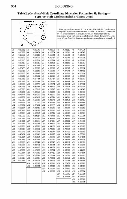
Table 2. (Continued) Hole Coordinate Dimension Factors for Jig Boring — Type “B” Hole Circles (English or Metric Units)
The diagram shows a type “B” circle for a 5-hole circle. Coordinates x, y are given in the table for hole circles of from 3 to 28 holes. Dimensions are for holes numbered in a counterclockwise direction (as shown). Dimensions given are based upon a hole circle of unit diameter. For a hole circle of, say, 3-inch or 3-centimeter diameter, multiply table values by 3.
JIG BORING 965
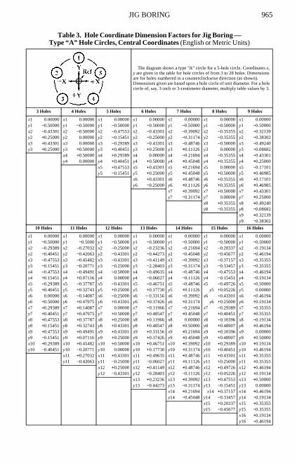
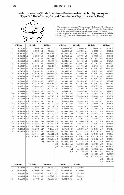
Table 3. Hole Coordinate Dimension Factors for Jig Boring — Type “A” Hole Circles, Central Coordinates (English or Metric Units)
The diagram shows a type “A” circle for a 5-hole circle. Coordinates x, y are given in the table for hole circles of from 3 to 28 holes. Dimensions are for holes numbered in a counterclockwise direction (as shown). Dimensions given are based upon a hole circle of unit diameter. For a hole circle of, say, 3-inch or 3-centimeter diameter, multiply table values by 3.
3 Holes 4 Holes 5 Holes 6 Holes 7 Holes 8 Holes 9 Holes
x1 0.00000 x1 0.00000 x1 0.00000 x1 0.00000 x1 0.00000 x1 0.00000 x1 0.00000y1 −0.50000 y1 −0.50000 y1 −0.50000 y1 −0.50000 y1 −0.50000 y1 −0.50000 y1 −0.50000x2 −0.43301 x2 −0.50000 x2 −0.47553 x2 −0.43301 x2 −0.39092 x2 −0.35355 x2 −0.32139y2 +0.25000 y2 0.00000 y2 −0.15451 y2 −0.25000 y2 −0.31174 y2 −0.35355 y2 −0.38302x3 +0.43301 x3 0.00000 x3 −0.29389 x3 −0.43301 x3 −0.48746 x3 −0.50000 x3 −0.49240y3 +0.25000 y3 +0.50000 y3 +0.40451 y3 +0.25000 y3 +0.11126 y3 0.00000 y3 −0.08682
x4 +0.50000 x4 +0.29389 x4 0.00000 x4 −0.21694 x4 −0.35355 x4 −0.43301y4 0.00000 y4 +0.40451 y4 +0.50000 y4 +0.45048 y4 +0.35355 y4 +0.25000
x5 +0.47553 x5 +0.43301 x5 +0.21694 x5 0.00000 x5 −0.17101y5 −0.15451 y5 +0.25000 y5 +0.45048 y5 +0.50000 y5 +0.46985
x6 +0.43301 x6 +0.48746 x6 +0.35355 x6 +0.17101y6 −0.25000 y6 +0.11126 y6 +0.35355 y6 +0.46985
x7 +0.39092 x7 +0.50000 x7 +0.43301y7 −0.31174 y7 0.00000 y7 +0.25000
x8 +0.35355 x8 +0.49240y8 −0.35355 y8 −0.08682
x9 +0.32139y9 −0.38302
10 Holes 11 Holes 12 Holes 13 Holes 14 Holes 15 Holes 16 Holes
x1 0.00000 x1 0.00000 x1 0.00000 x1 0.00000 x1 0.00000 x1 0.00000 x1 0.00000y1 −0.50000 y1 −0.5000 y1 −0.50000 y1 −0.50000 y1 −0.50000 y1 −0.50000 y1 −0.50000x2 −0.29389 x2 −0.27032 x2 −0.25000 x2 −0.23236 x2 −0.21694 x2 −0.20337 x2 −0.19134y2 −0.40451 y2 −0.42063 y2 −0.43301 y2 −0.44273 y2 −0.45048 y2 −0.45677 y2 −0.46194x3 −0.47553 x3 −0.45482 x3 −0.43301 x3 −0.41149 x3 −0.39092 x3 −0.37157 x3 −0.35355y3 −0.15451 y3 −0.20771 y3 −0.25000 y3 −2.28403 y3 −0.31174 y3 −0.33457 y3 −0.35355x4 −0.47553 x4 −0.49491 x4 −0.50000 x4 −0.49635 x4 −0.48746 x4 −0.47553 x4 −0.46194y4 +0.15451 y4 +0.07116 y4 0.00000 y4 −0.06027 y4 −0.11126 y4 −0.15451 y4 −0.19134x5 −0.29389 x5 −0.37787 x5 −0.43301 x5 −0.46751 x5 −0.48746 x5 −0.49726 x5 −0.50000y5 +0.40451 y5 +0.32743 y5 +0.25000 y5 +0.17730 y5 +0.11126 y5 +0.05226 y5 0.00000x6 0.00000 x6 −0.14087 x6 −0.25000 x6 − 0.33156 x6 −0.39092 x6 −0.43301 x6 −0.46194y6 +0.50000 y6 +0.47975 y6 +0.43301 y6 +0.37426 y6 +0.31174 y6 +0.25000 y6 +0.19134x7 +0.29389 x7 +0.14087 x7 0.00000 x7 −0.11966 x7 −0.21694 x7 −0.29389 x7 −0.35355y7 +0.40451 y7 +0.47975 y7 +0.50000 y7 +0.48547 y7 +0.45048 y7 +0.40451 y7 +0.35355x8 +0.47553 x8 +0.37787 x8 +0.25000 x8 +0.11966 x8 0.00000 x8 −0.10396 x8 −0.19134y8 +0.15451 y8 +0.32743 y8 +0.43301 y8 +0.48547 y8 +0.50000 y8 +0.48907 y8 +0.46194x9 +0.47553 x9 +0.49491 x9 +0.43301 x9 +0.33156 x9 +0.21694 x9 +0.10396 x9 0.00000y9 −0.15451 y9 +0.07116 y9 +0.25000 y9 +0.37426 y9 +0.45048 y9 +0.48907 y9 +0.50000x10 +0.29389 x10 +0.45482 x10 +0.50000 x10 +0.46751 x10 +0.39092 x10 +0.29389 x10 +0.19134y10 −0.40451 y10 −0.20771 y10 0.00000 y10 +0.17730 y10 +0.31174 y10 +0.40451 y10 +0.46194
x11 +0.27032 x11 +0.43301 x11 +0.49635 x11 +0.48746 x11 +0.43301 x11 +0.35355y11 −0.42063 y11 −0.25000 y11 −0.06027 y11 +0.11126 y11 +0.25000 y11 +0.35355
x12 +0.25000 x12 +0.41149 x12 +0.48746 x12 +0.49726 x12 +0.46194y12 −0.43301 y12 −0.28403 y12 −0.11126 y12 +0.05226 y12 +0.19134
x13 +0.23236 x13 +0.39092 x13 +0.47553 x13 +0.50000y13 −0.44273 y13 −0.31174 y13 −0.15451 y13 0.00000
x14 +0.21694 x14 +0.37157 x14 +0.46194y14 −0.45048 y14 −0.33457 y14 −0.19134
x15 +0.20337 x15 +0.35355y15 −0.45677 y15 −0.35355
x16 +0.19134y16 −0.46194
966 JIG BORING
17 Holes 18 Holes 19 Holes 20 Holes 21 Holes 22 Holes 23 Holes
x1 0.00000 x1 0.00000 x1 0.00000 x1 0.000000 x1 0.00000 x1 0.00000 x1 0.00000y1 −0.50000 y1 −0.50000 y1 −0.50000 y1 −0.50000 y1 −0.50000 y1 −0.50000 y1 −0.50000x2 −0.18062 x2 −0.17101 x2 −0.16235 x2 −0.15451 x2 −0.14738 x2 −0.14087 x2 −0.13490y2 −0.46624 y2 −0.46985 y2 −0.47291 y2 −0.47553 y2 −0.47779 y2 −0.47975 y2 −0.48146x3 −0.33685 x3 +0.32139 x3 −0.30711 x3 −0.29389 x3 −0.28166 x3 −0.27032 x3 −0.25979y3 −0.36950 y3 −0.38302 y3 −0.39457 y3 −0.40451 y3 −0.41312 y3 −0.42063 y3 −0.42721x4 −0.44758 x4 −0.43301 x4 −0.41858 x4 −0.40451 x4 −0.39092 x4 −0.37787 x4 −0.36542y4 −0.22287 y4 −0.25000 y4 −0.27347 y4 −0.29389 y4 −0.31174 y4 −0.32743 y4 −0.34128x5 −0.49787 x5 −0.49240 x5 −0.48470 x5 −0.47553 x5 −.046544 x5 −0.45482 x5 −0.44394y5 −0.04613 y5 −0.08682 y5 −0.12274 y5 −0.15451 y5 −0.18267 y5 −0.20771 y5 −0.23003x6 −0.48091 x6 −0.49420 x6 −0.49829 x6 −0.50000 x6 −0.49860 x6 −0.49491 x6 −0.48954y6 +0.13683 y6 +0.08682 y6 +0.04129 y6 0.00000 y6 −0.03737 y6 −0.07116 y6 −0.10173x7 −0.39901 x7 −0.43301 x7 −0.45789 x7 −0.47553 x7 −0.48746 x7 −0.49491 x7 −0.49883y7 +0.30132 y7 +0.25000 y7 +0.20085 y7 +0.15451 y7 +0.11126 y7 +0.07116 y7 +0.03412x8 −0.26322 x8 −0.32139 x8 −0.36786 x8 −0.40451 x8 −0.43301 x8 −0.45482 x8 −0.47113y8 +0.42511 y8 +0.38302 y8 +0.33864 y8 +0.29389 y8 +0.25000 y8 +0.20771 y8 +0.16744x9 −0.09187 x9 −0.17101 x9 −0.23797 x9 −0.29389 x9 −0.34009 x9 −0.37787 x9 −0.40848y9 +0.49149 y9 +0.46985 y9 +0.43974 y9 +0.40451 y9 +0.36653 y9 +0.32743 y9 +0.28834x10 +0.09187 x10 0.00000 x10 −0.08230 x10 −0.15451 x10 −0.21694 x10 −0.27032 x10 −0.31554y10 +0.49149 y10 +0.50000 y10 +0.49318 y10 +0.47553 y10 +0.45048 y10 +0.42063 y10 +0.38786x11 +0.26322 x11 +0.17101 x11 +0.08230 x11 0.00000 x11 −0.07452 x11 −0.14087 x11 −0.19920y11 +0.42511 y11 +0.46985 y11 +0.49318 y11 +0.50000 y11 +0.49442 y11 +0.47975 y11 +0.45861x12 +0.39901 x12 +0.32139 x12 +0.23797 x12 +0.15451 x12 +0.07452 x12 0.00000 x12 −0.06808y12 +0.30132 y12 +0.38302 y12 +0.43974 y12 +0.47553 y12 +0.49442 y12 +0.50000 y12 +0.49534x13 +0.48091 x13 +0.43301 x13 +0.36786 x13 +0.29389 x13 +0.21694 x13 +0.14087 x13 +0.06808y13 +0.13683 y13 +0.25000 y13 +0.33864 y13 +0.40451 y13 +0.45048 y13 +0.47975 y13 +0.49534x14 +0.49787 x14 +0.49240 x14 +0.45789 x14 +0.40451 x14 +0.34009 x14 +0.27032 x14 +0.19920y14 −0.04613 y14 +0.08682 y14 +0.20085 y14 +0.29389 y14 +0.36653 y14 +0.42063 y14 +0.45861x15 +0.44758 x15 +0.49240 x15 +0.49829 x15 +0.47553 x15 +0.43301 x15 +0.37787 x15 +0.31554y15 −0.22287 y15 −0.08682 y15 +0.04129 y15 +0.15451 y15 +0.25000 y15 +0.32743 y15 +0.38786x16 +0.33685 x16 +0.43301 x16 +0.48470 x16 +0.50000 x16 +0.48746 x16 +0.45482 x16 +0.40848y16 −0.36950 y16 −0.25000 y16 −0.12274 y16 0.00000 y16 +0.11126 y16 +0.20771 y16 +0.28834x17 +0.18062 x17 +0.32139 x17 +0.41858 x17 +0.47553 x17 +0.49860 x17 +0.49491 x17 +0.47113y17 −0.46624 y17 −0.38302 y17 −0.27347 y17 −0.15451 y17 −0.03737 y17 +0.07116 y17 +0.16744
x18 +0.17101 x18 +0.30711 x18 +0.40451 x18 +0.46544 x18 +0.49491 x18 +0.49883y18 −0.46985 y18 −0.39457 y18 −0.29389 y18 −0.18267 y18 −0.07116 y18 +0.03412
x19 + 0.16235 x19 +0.29389 x19 +0.39092 x19 +0.45482 x19 +0.48954y19 −0.47291 y19 −0.40451 y19 −0.31174 y19 −0.20771 y19 −0.10173
x20 +0.15451 x20 +0.28166 x20 +0.37787 x20 +0.44394y20 −0.47553 y20 −0.41312 y20 −0.32743 y20 −0.23003
x21 +0.14738 x21 +0.27032 x21 +0.36542y21 −0.47779 y21 −0.42063 y21 −0.34128
x22 +0.14087 x22 +0.25979y22 −0.47975 y22 −0.42721
x23 +0.13490y23 −0.48146
24 Holes 25 Holes 26 Holes 27 Holes 28 Holes
x1 0.00000 x1 0.00000 x1 0.00000 x1 0.00000 x1 0.00000y1 −0.50000 y1 −0.50000 y1 −0.50000 y1 −0.50000 y1 −0.50000
x2 −0.12941 x2 −0.12434 x2 −0.11966 x2 −0.11531 x2 −0.11126
y2 −0.48296 y2 −0.48429 y2 −0.48547 y2 −0.48652 y2 −0.48746
x3 −0.25000 x3 −0.24088 x3 −0.23236 x3 −0.22440 x3 −0.21694
Table 3. (Continued) Hole Coordinate Dimension Factors for Jig Boring — Type “A” Hole Circles, Central Coordinates (English or Metric Units)
The diagram shows a type “A” circle for a 5-hole circle. Coordinates x, y are given in the table for hole circles of from 3 to 28 holes. Dimensions are for holes numbered in a counterclockwise direction (as shown). Dimensions given are based upon a hole circle of unit diameter. For a hole circle of, say, 3-inch or 3-centimeter diameter, multiply table values by 3.
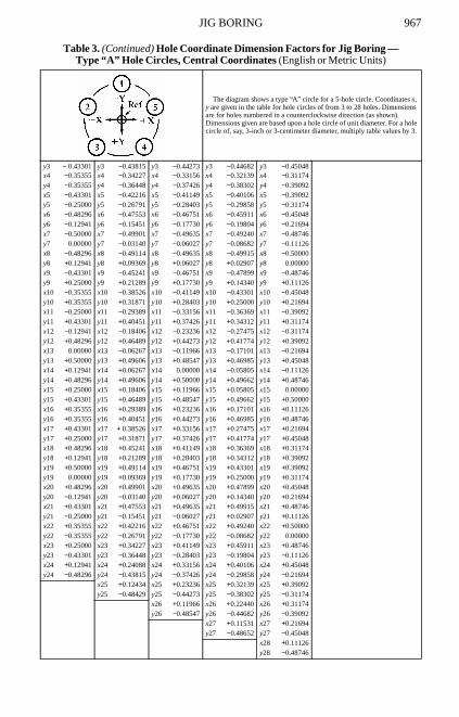
JIG BORING 967
y3 − 0.43301 y3 −0.43815 y3 −0.44273 y3 −0.44682 y3 −0.45048x4 −0.35355 x4 −0.34227 x4 −0.33156 x4 −0.32139 x4 −0.31174y4 −0.35355 y4 −0.36448 y4 −0.37426 y4 −0.38302 y4 −0.39092x5 −0.43301 x5 −0.42216 x5 −0.41149 x5 −0.40106 x5 −0.39092y5 −0.25000 y5 −0.26791 y5 −0.28403 y5 −0.29858 y5 −0.31174x6 −0.48296 x6 −0.47553 x6 −0.46751 x6 −0.45911 x6 −0.45048y6 −0.12941 y6 −0.15451 y6 −0.17730 y6 −0.19804 y6 −0.21694x7 −0.50000 x7 −0.49901 x7 −0.49635 x7 −0.49240 x7 −0.48746y7 0.00000 y7 −0.03140 y7 −0.06027 y7 −0.08682 y7 −0.11126x8 −0.48296 x8 −0.49114 x8 −0.49635 x8 −0.49915 x8 −0.50000y8 +0.12941 y8 +0.09369 y8 +0.06027 y8 +0.02907 y8 0.00000x9 −0.43301 x9 −0.45241 x9 −0.46751 x9 −0.47899 x9 −0.48746y9 +0.25000 y9 +0.21289 y9 +0.17730 y9 +0.14340 y9 +0.11126x10 −0.35355 x10 −0.38526 x10 −0.41149 x10 −0.43301 x10 −0.45048y10 +0.35355 y10 +0.31871 y10 +0.28403 y10 +0.25000 y10 +0.21694x11 −0.25000 x11 −0.29389 x11 −0.33156 x11 −0.36369 x11 −0.39092y11 +0.43301 y11 +0.40451 y11 +0.37426 y11 +0.34312 y11 +0.31174x12 −0.12941 x12 −0.18406 x12 −0.23236 x12 −0.27475 x12 −0.31174y12 +0.48296 y12 +0.46489 y12 +0.44273 y12 +0.41774 y12 +0.39092x13 0.00000 x13 −0.06267 x13 −0.11966 x13 −0.17101 x13 −0.21694y13 +0.50000 y13 +0.49606 y13 +0.48547 y13 +0.46985 y13 +0.45048x14 +0.12941 x14 +0.06267 x14 0.00000 x14 −0.05805 x14 −0.11126y14 +0.48296 y14 +0.49606 y14 +0.50000 y14 +0.49662 y14 +0.48746x15 +0.25000 x15 +0.18406 x15 +0.11966 x15 +0.05805 x15 0.00000y15 +0.43301 y15 +0.46489 y15 +0.48547 y15 +0.49662 y15 +0.50000x16 +0.35355 x16 +0.29389 x16 +0.23236 x16 +0.17101 x16 +0.11126y16 +0.35355 y16 +0.40451 y16 +0.44273 y16 +0.46985 y16 +0.48746x17 +0.43301 x17 + 0.38526 x17 +0.33156 x17 +0.27475 x17 +0.21694y17 +0.25000 y17 +0.31871 y17 +0.37426 y17 +0.41774 y17 +0.45048x18 +0.48296 x18 +0.45241 x18 +0.41149 x18 +0.36369 x18 +0.31174y18 +0.12941 y18 +0.21289 y18 +0.28403 y18 +0.34312 y18 +0.39092x19 +0.50000 x19 +0.49114 x19 +0.46751 x19 +0.43301 x19 +0.39092y19 0.00000 y19 +0.09369 y19 +0.17730 y19 +0.25000 y19 +0.31174x20 +0.48296 x20 +0.49901 x20 +0.49635 x20 +0.47899 x20 +0.45048y20 −0.12941 y20 −0.03140 y20 +0.06027 y20 +0.14340 y20 +0.21694x21 +0.43301 x21 +0.47553 x21 +0.49635 x21 +0.49915 x21 +0.48746y21 −0.25000 y21 −0.15451 y21 −0.06027 y21 +0.02907 y21 +0.11126x22 +0.35355 x22 +0.42216 x22 +0.46751 x22 +0.49240 x22 +0.50000y22 −0.35355 y22 −0.26791 y22 −0.17730 y22 −0.08682 y22 0.00000x23 +0.25000 x23 +0.34227 x23 +0.41149 x23 +0.45911 x23 +0.48746y23 −0.43301 y23 −0.36448 y23 −0.28403 y23 −0.19804 y23 −0.11126x24 +0.12941 x24 +0.24088 x24 +0.33156 x24 +0.40106 x24 +0.45048y24 −0.48296 y24 −0.43815 y24 −0.37426 y24 −0.29858 y24 −0.21694
x25 +0.12434 x25 +0.23236 x25 +0.32139 x25 +0.39092y25 −0.48429 y25 −0.44273 y25 −0.38302 y25 −0.31174
x26 +0.11966 x26 +0.22440 x26 +0.31174y26 −0.48547 y26 −0.44682 y26 −0.39092
x27 +0.11531 x27 +0.21694y27 −0.48652 y27 −0.45048
x28 +0.11126y28 −0.48746
Table 3. (Continued) Hole Coordinate Dimension Factors for Jig Boring — Type “A” Hole Circles, Central Coordinates (English or Metric Units)
The diagram shows a type “A” circle for a 5-hole circle. Coordinates x, y are given in the table for hole circles of from 3 to 28 holes. Dimensions are for holes numbered in a counterclockwise direction (as shown). Dimensions given are based upon a hole circle of unit diameter. For a hole circle of, say, 3-inch or 3-centimeter diameter, multiply table values by 3.
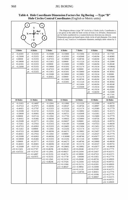
968 JIG BORING
Table 4. Hole Coordinate Dimension Factors for Jig Boring —Type “B” Hole Circles Central Coordinates (English or Metric units)
The diagram shows a type “B” circle for a 5-hole circle. Coordinates x, y are given in the table for hole circles of from 3 to 28 holes. Dimensions are for holes numbered in a counterclockwise direction (as shown). Dimensions given are based upon a hole circle of unit diameter. For a hole circle of, say, 3-inch or 3-centimeter diameter, multiply table values by 3.
3 Holes 4 Holes 5 Holes 6 Holes 7 Holes 8 Holes 9 Holes
x1 −0.43301 x1 −0.35355 x1 −0.29389 x1 −0.25000 x1 −0.21694 x1 −0.19134 x1 −0.17101y1 −0.25000 y1 −0.35355 y1 −0.40451 y1 −0.43301 y1 −0.45048 y1 −0.46194 y1 −0.46985x2 0.00000 x2 −0.35355 x2 −0.47553 x2 −0.50000 x2 −0.48746 x2 −0.46194 x2 −0.43301y2 +0.50000 y2 +0.35355 y2 +0.15451 y2 0.00000 y2 −0.11126 y2 −0.19134 y2 −0.25000x3 +0.43301 x3 +0.35355 x3 0.00000 x3 −0.25000 x3 −0.39092 x3 −0.46194 x3 −0.49240y3 −0.25000 y3 +0.35355 y3 +0.50000 y3 +0.43301 y3 +0.31174 y3 +0.19134 y3 +0.08682
x4 +0.35355 x4 +0.47553 x4 +0.25000 x4 0.00000 x4 −0.19134 x4 −0.32139y4 −0.35355 y4 +0.15451 y4 +0.43301 y4 +0.50000 y4 +0.46194 y4 +0.38302
x5 +0.29389 x5 +0.50000 x5 +0.39092 x5 +0.19134 x5 0.00000y5 −0.40451 y5 0.00000 y5 +0.31174 y5 +0.46194 y5 +0.50000
x6 +0.25000 x6 +0.48746 x6 +0.46194 x6 +0.32139y6 −0.43301 y6 −0.11126 y6 +0.19134 y6 +0.38302
x7 +0.21694 x7 +0.46194 x7 +0.49240y7 −0.45048 y7 −0.19134 y7 +0.08682
x8 +0.19134 x8 +0.43301y8 −0.46194 y8 −0.25000
x9 +0.17101y9 −0.46985
10 Holes 11 Holes 12 Holes 13 Holes 14 Holes 15 Holes 16 Holes
x1 −0.15451 x1 −0.14087 x1 −0.12941 x1 −0.11966 x1 −0.11126 x1 −0.10396 x1 −0.09755y1 −0.47553 y1 −0.47975 y1 −0.48296 y1 −0.48547 y1 −0.48746 y1 −0.48907 y1 −0.49039x2 −0.40451 x2 −0.37787 x2 −0.35355 x2 −0.33156 x2 −0.31174 x2 −0.29389 x2 −0.27779y2 −0.29389 y2 −0.32743 y2 −0.35355 y2 −0.37426 y2 −0.39092 y2 −0.40451 y2 −0.41573x3 −0.50000 x3 −0.49491 x3 −0.48296 x3 −0.46751 x3 −0.45048 x3 −0.43301 x3 −0.41573y3 0.00000 y3 −0.07116 y3 −0.12941 y3 −0.17730 y3 −0.21694 y3 −0.25000 y3 −0.27779x4 −0.40451 x4 −0.45482 x4 −0.48296 x4 −0.49635 x4 −0.50000 x4 −0.49726 x4 −0.49039y4 +0.29389 y4 +0.20771 y4 +0.12941 y4 +0.06027 y4 0.00000 y4 −0.05226 y4 −0.09755x5 −0.15451 x5 −0.27032 x5 −0.35355 x5 −0.41149 x5 −0.45048 x5 −0.47553 x5 −0.49039y5 +0.47553 y5 +0.42063 y5 +0.35355 y5 +0.28403 y5 +0.21694 y5 +0.15451 y5 +0.09755x6 +0.15451 x6 0.00000 x6 −0.12941 x6 −0.23236 x6 −0.31174 x6 −0.37157 x6 −0.41573y6 +0.47553 y6 +0.50000 y6 +0.48296 y6 +0.44273 y6 +0.39092 y6 +0.33457 y6 +0.27779x7 +0.40451 x7 +0.27032 x7 +0.12941 x7 0.00000 x7 −0.11126 x7 −0.20337 x7 −0.27779y7 +0.29389 y7 +0.42063 y7 +0.48296 y7 + 0.50000 y7 +0.48746 y7 +0.45677 y7 +0.41573x8 +0.50000 x8 +0.45482 x8 +0.35355 x8 +0.23236 x8 +0.11126 x8 0.00000 x8 −0.09755y8 0.00000 y8 +0.20771 y8 +0.35355 y8 +0.44273 y8 +0.48746 y8 +0.50000 y8 +0.49039x9 +0.40451 x9 +0.49491 x9 +0.48296 x9 +0.41149 x9 +0.31174 x9 +0.20337 x9 +0.09755y9 −0.29389 y9 −0.07116 y9 +0.12941 y9 +0.28403 y9 +0.39092 y9 +0.45677 y9 +0.49039x10 +0.15451 x10 +0.37787 x10 +0.48296 x10 +0.49635 x10 +0.45048 x10 +0.37157 x10 +0.27779y10 −0.47553 y10 −0.32743 y10 −0.12941 y10 +0.06027 y10 +0.21694 y10 +0.33457 y10 +0.41573
x11 +0.14087 x11 +0.35355 x11 +0.46751 x11 +0.50000 x11 +0.47553 x11 +0.41573y11 −0.47975 y11 −0.35355 y11 −0.17730 y11 0.00000 y11 +0.15451 y11 +0.27779
x12 +0.12941 x12 +0.33156 x12 +0.45048 x12 +0.49726 x12 +0.49039y12 −0.48296 y12 −0.37426 y12 −0.21694 y12 −0.05226 y12 +0.09755
x13 +0.11966 x13 +0.31174 x13 +0.43301 x13 +0.49039y13 −0.48547 y13 −0.39092 y13 −0.25000 y13 −0.09755
x14 +0.11126 x14 +0.29389 x14 +0.41573y14 − 0.48746 y14 −0.40451 y14 −0.27779
x15 +0.10396 x15 +0.27779y15 −0.48907 y15 −0.41573
x16 +0.09755y16 −0.49039
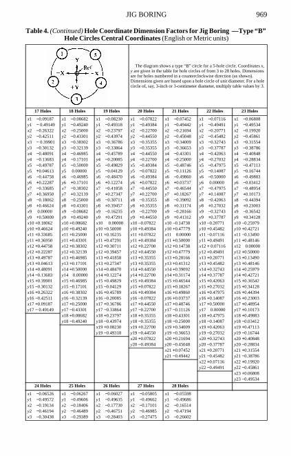
JIG BORING 969
17 Holes 18 Holes 19 Holes 20 Holes 21 Holes 22 Holes 23 Holes
x1 −0.09187 x1 −0.08682 x1 −0.08230 x1 −0.07822 x1 −0.07452 x1 −0.07116 x1 −0.06808y1 − 0.49149 y1 −0.49240 y1 −0.49318 y1 −0.49384 y1 −0.49442 y1 −0.49491 y1 −0.49534x2 −0.26322 x2 −0.25000 x2 −0.23797 x2 −0.22700 x2 −0.21694 x2 −0.20771 x2 −0.19920y2 −0.42511 y2 −0.43301 y2 −0.43974 y2 −0.44550 y2 −0.45048 y2 −0.45482 y2 −0.45861x3 − 0.39901 x3 −0.38302 x3 −0.36786 x3 −0.35355 x3 −0.34009 x3 −0.32743 x3 −0.31554y3 −0.30132 y3 −0.32139 y3 −0.33864 y3 −0.35355 y3 −0.36653 y3 −0.37787 y3 −0.38786x4 −0.48091 x4 −0.46985 x4 −0.45789 x4 −0.44550 x4 −0.43301 x4 −0.42063 x4 −0.40848y4 −0.13683 y4 −0.17101 y4 −0.20085 y4 −0.22700 y4 −0.25000 y4 −0.27032 y4 −0.28834x5 −0.49787 x5 −0.50000 x5 −0.49829 x5 −0.49384 x5 −0.48746 x5 −0.47975 x5 −0.47113y5 +0.04613 y5 0.00000 y5 −0.04129 y5 −0.07822 y5 −0.11126 y5 −0.14087 y5 −0.16744x6 −0.44758 x6 −0.46985 x6 −0.48470 x6 −0.49384 x6 −0.49860 x6 −0.50000 x6 −0.49883y6 +0.22287 y6 +0.17101 y6 +0.12274 y6 +0.07822 y6 +0.03737 y6 0.00000 y6 −0.03412x7 −0.33685 x7 −0.38302 x7 −0.41858 x7 −0.44550 x7 −0.46544 x7 −0.47975 x7 −0.48954y7 +0.36950 y7 +0.32139 y7 +0.27347 y7 +0.22700 y7 +0.18267 y7 +0.14087 y7 +0.10173x8 −0.18062 x8 −0.25000 x8 −0.30711 x8 −0.35355 x8 −0.39092 x8 −0.42063 x8 −0.44394y8 +0.46624 y8 +0.43301 y8 +0.39457 y8 +0.35355 y8 +0.31174 y8 +0.27032 y8 +0.23003x9 0.00000 x9 −0.08682 x9 −0.16235 x9 −0.22700 x9 −0.28166 x9 −0.32743 x9 −0.36542y9 +0.50000 y9 +0.49240 y9 +0.47291 y9 +0.44550 y9 +0.41312 y9 +0.37787 y9 +0.34128x10 +0.18062 x10 +0.08682 x10 0.00000 x10 −0.07822 x10 −0.14738 x10 −0.20771 x10 −0.25979y10 +0.46624 y10 +0.49240 y10 +0.50000 y10 +0.49384 y10 +0.47779 y10 +0.45482 y10 +0.42721x11 +0.33685 x11 +0.25000 x11 +0.16235 x11 +0.07822 x11 0.00000 x11 −0.07116 x11 −0.13490y11 +0.36950 y11 +0.43301 y11 +0.47291 y11 +0.49384 y11 +0.50000 y11 +0.49491 y11 +0.48146x12 +0.44758 x12 +0.38302 x12 +0.30711 x12 +0.22700 x12 +0.14738 x12 + 0.07116 x12 0.00000y12 +0.22287 y12 +0.32139 y12 +0.39457 y12 +0.44550 y12 +0.47779 y12 +0.49491 y12 +0.50000x13 +0.49787 x13 +0.46985 x13 +0.41858 x13 +0.35355 x13 +0.28166 x13 +0.20771 x13 +0.13490y13 +0.04613 y13 +0.17101 y13 +0.27347 y13 +0.35355 y13 +0.41312 y13 +0.45482 y13 +0.48146x14 +0.48091 x14 +0.50000 x14 +0.48470 x14 +0.44550 x14 +0.39092 x14 +0.32743 x14 +0.25979y14 −0.13683 y14 0.00000 y14 +0.12274 y14 +0.22700 y14 +0.31174 y14 +0.37787 y14 +0.42721x15 +0.39901 x15 +0.46985 x15 +0.49829 x15 +0.49384 x15 +0.46544 x15 +0.42063 x15 +0.36542y15 −0.30132 y15 −0.17101 y15 −0.04129 y15 +0.07822 y15 +0.18267 y15 +0.27032 y15 +0.34128x16 +0.26322 x16 +0.38302 x16 +0.45789 x16 +0.49384 x16 +0.49860 x16 +0.47975 x16 +0.44394y16 −0.42511 y16 −0.32139 y16 −0.20085 y16 −0.07822 y16 +0.03737 y16 +0.14087 y16 +0.23003x17 +0.09187 x17 +0.25000 x17 +0.36786 x17 +0.44550 x17 +0.48746 x17 +0.50000 x17 +0.48954y17 − 0.49149 y17 −0.43301 y17 −0.33864 y17 −0.22700 y17 −0.11126 y17 0.00000 y17 +0.10173
x18 +0.08682 x18 +0.23797 x18 +0.35355 x18 +0.43301 x18 +0.47975 x18 +0.49883y18 −0.49240 y18 −0.43974 y18 −0.35355 y18 −0.25000 y18 −0.14087 y18 −0.03412
x19 +0.08230 x19 +0.22700 x19 +0.34009 x19 +0.42063 x19 +0.47113y19 −0.49318 y19 −0.44550 y19 −0.36653 y19 −0.27032 y19 −0.16744
x20 +0.07822 x20 +0.21694 x20 +0.32743 x20 +0.40848y20 −0.49384 y20 −0.45048 y20 −0.37787 y20 −0.28834
x21 +0.07452 x21 +0.20771 x21 +0.31554y21 −0.49442 y21 −0.45482 y21 −0.38786
x22 +0.07116 x22 +0.19920y22 −0.49491 y22 −0.45861
x23 +0.06808y23 −0.49534
24 Holes 25 Holes 26 Holes 27 Holes 28 Holes
x1 −0.06526 x1 −0.06267 x1 −0.06027 x1 −0.05805 x1 −0.05598y1 −0.49572 y1 −0.49606 y1 −0.49635 y1 −0.49662 y1 −0.49686x2 −0.19134 x2 −0.18406 x2 −0.17730 x2 −0.17101 x2 −0.16514y2 −0.46194 y2 −0.46489 y2 −0.46751 y2 −0.46985 y2 −0.47194x3 −0.30438 x3 −0.29389 x3 −0.28403 x3 −0.27475 x3 −0.26602
Table 4. (Continued) Hole Coordinate Dimension Factors for Jig Boring —Type “B” Hole Circles Central Coordinates (English or Metric units)
The diagram shows a type “B” circle for a 5-hole circle. Coordinates x, y are given in the table for hole circles of from 3 to 28 holes. Dimensions are for holes numbered in a counterclockwise direction (as shown). Dimensions given are based upon a hole circle of unit diameter. For a hole circle of, say, 3-inch or 3-centimeter diameter, multiply table values by 3.
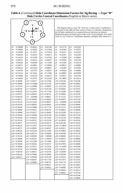
970 JIG BORING
y3 −0.39668 y3 −0.40451 y3 −0.41149 y3 −0.41774 y3 −0.42336x4 −0.39668 x4 −0.38526 x4 −0.37426 x4 −0.36369 x4 −0.35355y4 −0.30438 y4 −0.31871 y4 −0.33156 y4 −0.34312 y4 −0.35355x5 −0.46194 x5 −0.45241 x5 −0.44273 x5 −0.43301 x5 −0.42336y5 −0.19134 y5 −0.21289 y5 −0.23236 y5 − 0.25000 y5 −0.26602x6 −0.49572 x6 −0.49114 x6 −0.48547 x6 −0.47899 x6 −0.47194y6 −0.06526 y6 −0.09369 y6 −0.11966 y6 −0.14340 y6 −0.16514x7 −0.49572 x7 −0.49901 x7 −0.50000 x7 −0.49915 x7 −0.49686y7 +0.06526 y7 +0.03140 y7 0.00000 y7 − 0.02907 y7 −0.05598x8 −0.46194 x8 −0.47553 x8 −0.48547 x8 −0.49240 x8 −0.49686y8 +0.19134 y8 +0.15451 y8 +0.11966 y8 +0.08682 y8 +0.05598x9 −0.39668 x9 −0.42216 x9 −0.44273 x9 −0.45911 x9 −0.47194y9 +0.30438 y9 +0.26791 y9 +0.23236 y9 +0.19804 y9 +0.16514x10 −0.30438 x10 −0.34227 x10 −0.37426 x10 −0.40106 x10 −0.42336y10 +0.39668 y10 + 0.36448 y10 +0.33156 y10 +0.29858 y10 +0.26602x11 −0.19134 x11 −0.24088 x11 −0.28403 x11 −0.32139 x11 −0.35355y11 +0.46194 y11 +0.43815 y11 +0.41149 y11 +0.38302 y11 +0.35355x12 −0.06526 x12 −0.12434 x12 −0.17730 x12 −0.22440 x12 −0.26602y12 +0.49572 y12 +0.48429 y12 +0.46751 y12 +0.44682 y12 +0.42336x13 +0.06526 x13 0.00000 x13 −0.06027 x13 −0.11531 x13 −0.16514y13 +0.49572 y13 +0.50000 y13 +0.49635 y13 +0.48652 y13 +0.47194x14 +0.19134 x14 +0.12434 x14 +0.06027 x14 0.00000 x14 −0.05598y14 +0.46194 y14 +0.48429 y14 +0.49635 y14 +0.50000 y14 +0.49686x15 +0.30438 x15 +0.24088 x15 +0.17730 x15 +0.11531 x15 +0.05598y15 +0.39668 y15 +0.43815 y15 +0.46751 y15 +0.48652 y15 +0.49686x16 +0.39668 x16 +0.34227 x16 +0.28403 x16 +0.22440 x16 +0.16514y16 +0.30438 y16 +0.36448 y16 +0.41149 y16 +0.44682 y16 +0.47194x17 +0.46194 x17 +0.42216 x17 +0.37426 x17 +0.32139 x17 +0.26602y17 +0.19134 y17 +0.26791 y17 +0.33156 y17 +0.38302 y17 +0.42336x18 +0.49572 x18 +0.47553 x18 +0.44273 x18 +0.40106 x18 +0.35355y18 +0.06526 y18 +0.15451 y18 +0.23236 y18 + 0.29858 y18 +0.35355x19 +0.49572 x19 +0.49901 x19 +0.48547 x19 +0.45911 x19 +0.42336y19 −0.06526 y19 +0.03140 y19 +0.11966 y19 +0.19804 y19 +0.26602x20 +0.46194 x20 +0.49114 x20 +0.50000 x20 +0.49240 x20 +0.47194y20 −0.19134 y20 −0.09369 y20 0.00000 y20 +0.08682 y20 +0.16514x21 +0.39668 x21 +0.45241 x21 + 0.48547 x21 +0.49915 x21 +0.49686y21 −0.30438 y21 −0.21289 y21 −0.11966 y21 −0.02907 y21 +0.05598x22 +0.30438 x22 +0.38526 x22 +0.44273 x22 +0.47899 x22 +0.49686y22 −0.39668 y22 −0.31871 y22 −0.23236 y22 − 0.14340 y22 −0.05598x23 +0.19134 x23 +0.29389 x23 +0.37426 x23 +0.43301 x23 +0.47194y23 −0.46194 y23 −0.40451 y23 −0.33156 y23 −0.25000 y23 −0.16514x24 +0.06526 x24 +0.18406 x24 +0.28403 x24 +0.36369 x24 +0.42336y24 −0.49572 y24 −0.46489 y24 −0.41149 y24 −0.34312 y24 −0.26602
x25 +0.06267 x25 +0.17730 x25 +0.27475 x25 +0.35355y25 −0.49606 y25 −0.46751 y25 −0.41774 y25 −0.35355
x26 +0.06027 x26 +0.17101 x26 +0.26602y26 −0.49635 y26 −0.46985 y26 −0.42336
x27 +0.05805 x27 +0.16514y27 −0.49662 y27 −0.47194
x28 +0.05598y28 −0.49686
Table 4. (Continued) Hole Coordinate Dimension Factors for Jig Boring —Type “B” Hole Circles Central Coordinates (English or Metric units)
The diagram shows a type “B” circle for a 5-hole circle. Coordinates x, y are given in the table for hole circles of from 3 to 28 holes. Dimensions are for holes numbered in a counterclockwise direction (as shown). Dimensions given are based upon a hole circle of unit diameter. For a hole circle of, say, 3-inch or 3-centimeter diameter, multiply table values by 3.
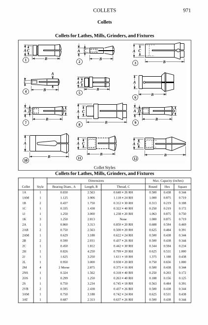
COLLETS 971
Collets
Collets for Lathes, Mills, Grinders, and Fixtures
Collet Styles
Collets for Lathes, Mills, Grinders, and Fixtures
Collet Style
Dimensions Max. Capacity (inches)
Bearing Diam., A Length, B Thread, C Round Hex Square
1A 1 0.650 2.563 0.640 × 26 RH 0.500 0.438 0.344
1AM 1 1.125 3.906 1.118 × 24 RH 1.000 0.875 0.719
1B 2 0.437 1.750 0.312 × 30 RH 0.313 0.219 0.188
1C 1 0.335 1.438 0.322 × 40 RH 0.250 0.219 0.172
1J 1 1.250 3.000 1.238 × 20 RH 1.063 0.875 0.750
1K 3 1.250 2.813 None 1.000 0.875 0.719
2A 1 0.860 3.313 0.850 × 20 RH 0.688 0.594 0.469
2AB 2 0.750 2.563 0.500 × 20 RH 0.625 0.484 0.391
2AM 1 0.629 3.188 0.622 × 24 RH 0.500 0.438 0.344
2B 2 0.590 2.031 0.437 × 26 RH 0.500 0.438 0.344
2C 1 0.450 1.812 0.442 × 30 RH 0.344 0.594 0.234
2H 1 0.826 4.250 0.799 × 20 RH 0.625 0.531 1.000
2J 1 1.625 3.250 1.611 × 18 RH 1.375 1.188 0.438
2L 1 0.950 3.000 0.938 × 20 RH 0.750 0.656 1.000
2M 4 2 Morse 2.875 0.375 × 16 RH 0.500 0.438 0.344
2NS 1 0.324 1.562 0.318 × 40 RH 0.250 0.203 0.172
2OS 1 0.299 1.250 0.263 × 40 RH 0.188 0.156 0.125
2S 1 0.750 3.234 0.745 × 18 RH 0.563 0.484 0.391
2VB 2 0.595 2.438 0.437 × 26 RH 0.500 0.438 0.344
3AM 1 0.750 3.188 0.742 × 24 RH 0.625 0.531 0.438
3AT 1 0.687 2.313 0.637 × 26 RH 0.500 0.438 0.344
A
1
C
B
A
A D C
B
B
C
B
A
4
A
5
C
B
7
A D C
B9
A C
B2
10
A C
B8
A
3
A C
B12
A C
B11
A
B
B
6
C
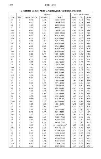
972 COLLETS
3B 2 0.875 3.438 0.625 × 16 RH 0.750 0.641 0.531
3C 1 0.650 2.688 0.640 × 26 RH 0.500 0.438 0.344
3H 1 1.125 4.438 1.050 × 20 RH 0.875 0.750 0.625
3J 1 2.000 3.750 1.988 × 20 RH 1.750 1.500 1.250
3NS 1 0.687 2.875 0.647 × 20 RH 0.500 0.438 0.344
3OS 1 0.589 2.094 0.518 × 26 RH 0.375 0.313 0.266
3PN 1 0.650 2.063 0.645 × 24 RH 0.500 0.438 0.344
3PO 1 0.599 2.063 0.500 × 24 RH 0.375 0.313 0.266
3S 1 1.000 4.594 0.995 × 20 RH 0.750 0.656 0.531
3SC 1 0.350 1.578 0.293 × 36 RH 0.188 0.156 0.125
3SS 1 0.589 2.125 0.515 × 26 RH 0.375 0.313 0.266
4C 1 0.950 3.000 0.938 × 20 RH 0.750 0.656 0.531
4NS 1 0.826 3.500 0.800 × 20 RH 0.625 0.531 0.438
4OS 1 0.750 2.781 0.660 × 20 RH 0.500 0.438 0.344
4PN 1 1.000 2.906 0.995 × 16 RH 0.750 0.656 0.531
4S 1 0.998 3.250 0.982 × 20 RH 0.750 0.656 0.531
5C 1 1.250 3.281 1.238 × 20 RHa 1.063 0.906 0.750
5M 5 1.438 3.438 1.238 × 20 RH 0.875 0.750 0.625
5NS 1 1.062 4.219 1.050 × 20 RH 0.875 0.750 0.625
5OS 1 3.500 3.406 0.937 × 18 RH 0.750 0.641 0.516
5P 1 0.812 3.687 0.807 × 24 RH 0.625 0.531 0.438
5PN 1 1.312 3.406 1.307 × 16 RH 1.000 0.875 0.719
5SC 1 0.600 2.438 0.500 × 26 RH 0.375 0.328 0.266
5ST 1 1.250 3.281 1.238 × 20 RH 1.063 0.906 0.750
5V 1 0.850 3.875 0.775 × 18 RH 0.563 0.484 0.391
6H 1 1.375 4.750 1.300 × 10 RH 1.125 0.969 0.797
6K 1 0.842 3.000 0.762 × 26 RH 0.625 0.531 0.438
6L 1 1.250 4.438 1.178 × 20 RH 1.000 0.875 0.719
6NS 1 1.312 5.906 1.234 × 14 RH 1.000 0.859 0.703
6R 1 1.375 4.938 1.300 × 20 RH 1.125 0.969 0.781
7B 4 7 B&S 3.125 0.375 × 16 RH 0.500 0.406 0.344
7 B&S 4 7 B&S 2.875 0.375 × 16 RH 0.500 0.406 0.344
7P 1 1.125 4.750 1.120 × 20 RH 0.875 0.750 0.625
7R 6 1.062 3.500 None 0.875 0.750 0.625
8H 1 1.500 4.750 1.425 × 20 RH 1.250 1.063 0.875
8ST 1 2.375 5.906 2.354 × 12 RH 2.125 1.844 1.500
8WN 1 1.250 3.875 1.245 × 16 RH 1.000 0.875 0.719
9B 4 9 B&S 4.125 0.500 × 13 RH 0.750 0.641 0.531
10L 1 1.562 5.500 1.490 × 18 RH 1.250 1.063 0.875
10P 1 1.500 4.750 1.495 × 20 RH 1.250 1.063 0.875
16C 1 1.889 4.516 1.875 × 1.75 mm RHb 1.625 1.406 1.141
20W 1 0.787 2.719 0.775 × 6–1 cm 0.563 0.484 0.391
22J 1 2.562 4.000 2.550 × 18 RH 2.250 1.938 1.563
32S 1 0.703 2.563 0.690 × 24 RH 0.500 0.438 0.344
35J 1 3.875 5.000 3.861 × 18 RH 3.500 3.000 2.438
42S 1 1.250 3.688 1.236 × 20 RH 1.000 0.875 0.719
50V 8 1.250 4.000 1.125 × 24 RH 0.938 0.813 0.656
52SC 1 0.800 3.688 0.795 × 20 RH 0.625 0.531 0.438
115 1 1.344 3.500 1.307 × 20 LH 1.125 0.969 0.797
Collets for Lathes, Mills, Grinders, and Fixtures (Continued)
Collet Style
Dimensions Max. Capacity (inches)
Bearing Diam., A Length, B Thread, C Round Hex Square
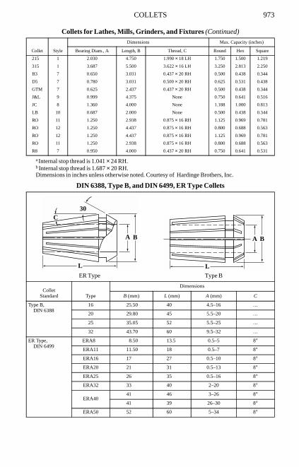
COLLETS 973
Dimensions in inches unless otherwise noted. Courtesy of Hardinge Brothers, Inc.
DIN 6388, Type B, and DIN 6499, ER Type Collets
215 1 2.030 4.750 1.990 × 18 LH 1.750 1.500 1.219
315 1 3.687 5.500 3.622 × 16 LH 3.250 2.813 2.250
B3 7 0.650 3.031 0.437 × 20 RH 0.500 0.438 0.344
D5 7 0.780 3.031 0.500 × 20 RH 0.625 0.531 0.438
GTM 7 0.625 2.437 0.437 × 20 RH 0.500 0.438 0.344
J&L 9 0.999 4.375 None 0.750 0.641 0.516
JC 8 1.360 4.000 None 1.188 1.000 0.813
LB 10 0.687 2.000 None 0.500 0.438 0.344
RO 11 1.250 2.938 0.875 × 16 RH 1.125 0.969 0.781
RO 12 1.250 4.437 0.875 × 16 RH 0.800 0.688 0.563
RO 12 1.250 4.437 0.875 × 16 RH 1.125 0.969 0.781
RO 11 1.250 2.938 0.875 × 16 RH 0.800 0.688 0.563
R8 7 0.950 4.000 0.437 × 20 RH 0.750 0.641 0.531
a Internal stop thread is 1.041 × 24 RH. b Internal stop thread is 1.687 × 20 RH.
ER Type Type B
ColletStandard Type
Dimensions
B (mm) L (mm) A (mm) C
Type B,DIN 6388
16 25.50 40 4.5–16 …
20 29.80 45 5.5–20 …
25 35.05 52 5.5–25 …
32 43.70 60 9.5–32 …
ER Type,DIN 6499
ERA8 8.50 13.5 0.5–5 8°
ERA11 11.50 18 0.5–7 8°
ERA16 17 27 0.5–10 8°
ERA20 21 31 0.5–13 8°
ERA25 26 35 0.5–16 8°
ERA32 33 40 2–20 8°
ERA4041 46 3–26 8°
41 39 26–30 8°
ERA50 52 60 5–34 8°
Collets for Lathes, Mills, Grinders, and Fixtures (Continued)
Collet Style
Dimensions Max. Capacity (inches)
Bearing Diam., A Length, B Thread, C Round Hex Square
L
A
C30
B A B
L