Embed Size (px)
Citation preview

Abstract
JFFS2, the Journalling Flash File System version 2, is widely used in the embeddedsystems world. It was designed for relatively small flash chips and has serious problemswhen it is used on large flash devices. Unfortunately, these scalability problems are deepinside the design of the file system, and cannot be solved without full redesign.
This document describes JFFS3 – a new flash file system which is designed to bescalable.
Contents
1 JFFS2 overview 1
2 JFFS3 Requirements 2
3 Introduction to JFFS3 33.1 Indexing problem . . . . . . . . . . . . . . . . . . . . . . . . . . . . . . . 33.2 Wandering trees . . . . . . . . . . . . . . . . . . . . . . . . . . . . . . . . 43.3 B-trees . . . . . . . . . . . . . . . . . . . . . . . . . . . . . . . . . . . . . 53.4 Indexing in JFFS3 . . . . . . . . . . . . . . . . . . . . . . . . . . . . . . 63.5 Indexing example . . . . . . . . . . . . . . . . . . . . . . . . . . . . . . . 83.6 The Journal . . . . . . . . . . . . . . . . . . . . . . . . . . . . . . . . . . 93.7 Garbage collection . . . . . . . . . . . . . . . . . . . . . . . . . . . . . . 103.8 The superblock . . . . . . . . . . . . . . . . . . . . . . . . . . . . . . . . 12
4 The tree 134.1 Objects . . . . . . . . . . . . . . . . . . . . . . . . . . . . . . . . . . . . 134.2 Keys . . . . . . . . . . . . . . . . . . . . . . . . . . . . . . . . . . . . . . 14
4.2.1 Trivial key scheme . . . . . . . . . . . . . . . . . . . . . . . . . . 154.2.2 Keys comparison . . . . . . . . . . . . . . . . . . . . . . . . . . . 164.2.3 Key schemes . . . . . . . . . . . . . . . . . . . . . . . . . . . . . . 164.2.4 Keys compression . . . . . . . . . . . . . . . . . . . . . . . . . . . 17
4.3 Links . . . . . . . . . . . . . . . . . . . . . . . . . . . . . . . . . . . . . . 19
5 Garbage Collection 20
6 The superblock 206.1 The superblock management algorithm . . . . . . . . . . . . . . . . . . . 206.2 The length of the chain . . . . . . . . . . . . . . . . . . . . . . . . . . . . 236.3 The superblock search . . . . . . . . . . . . . . . . . . . . . . . . . . . . 25
7 Issues/ideas/to be done 26
8 Definitions 27
9 Symbols 31
10 Abbreviations 32
11 Credits 32
12 References 33
1 JFFS2 overview
JFFS2, the Journalling Flash File System version 2 [1] is widely used in the embeddedsystems world. JFFS2 was originally designed for small NOR flashes (less then about32MB) and the first device with JFFS2 file system was a small bar-code scanner. Later,when NAND flashes became widely used, NAND support was added to JFFS2. The firstNAND flashes were also small enough, but grew in size very quickly and are currentlymuch larger then 32MB (e.g., Samsung produces 2GB NAND flashes [4]).
JFFS2 has log-structured design, which basically means, that the whole file systemmay be regarded as one large log. Any file system modification (i.e., file change, directorycreation, changing file’s attributes, etc) is appended to the log. The log is the only datastructure on the flash media. Modifications are encapsulated into small data structurescalled nodes.
So, JFFS2 is roughly a log, the log consists of nodes, each node contains a file systemmodification. And this is basically all JFFS2 file system is. It is very simple from thephysical layout’s standpoint. For more information about the design of JFFS2 and aboutthe log-structured design, look at [1], [2], and [3].
It is not the goal of this chapter to delve into details of JFFS2 but it is still wantedto provide enough information to make it clear why JFFS2 has scalability problems andwhy JFFS3 is needed. To keep this chapter simple, terms index or indexing informationare used.
The index is a crucial part of any file system as it is used to keep track of everythingthat is stored in the file system. For example, the index may help to quickly locate theaddresses of physical blocks which correspond to the specified file at the specified offset,or it helps to quickly find all the directory entries in a specified directory and so on.
For example, in case of ext2, the inode table, the bitmap and the set of direct, indirect,doubly indirect and triply indirect pointers may be considered the index. In case of theFAT file system, the File Allocation Table may be considered as the index, etc.
In traditional file systems the index is usually kept and maintained on the media, butunfortunately, this is not the case for JFFS2. In JFFS2, the index is maintained in RAM,not on the flash media. And this is the root of all the JFFS2 scalability problems.
Of course, as the index in kept in RAM, JFFS2 achieves extremely high throughput,just because it does not need to update the index on flash after something has beenchanged in the file system. And this works very well for relatively small flashes, for whichJFFS2 was originally designed. But as soon as one tries to use JFFS2 on large flashes(starting from about 128MB), many problems come up.
At first, it is obvious that JFFS2 needs to build the index in RAM when it mountsthe file system. For this reason, it needs to scan the entire flash partition in order tolocate all the nodes which are present there. So, the larger is JFFS2 partition, the morenodes it has, the longer it takes to mount it.
The second, it is evidently that the index consumes some RAM. And the larger is theJFFS2 file system, the more nodes it has, the more memory is consumed.
To put it differently, if S is the size of the JFFS3 flash partition 1,
• JFFS2 mount time scales as O(S) (linearly);
• JFFS2 memory consumption scales as O(S) (linearly).
1Note, all the symbols used in this document are summarized in section 9
1
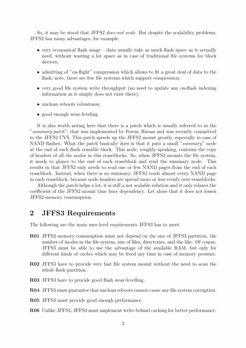
So, it may be stood that JFFS2 does not scale. But despite the scalability problems,JFFS2 has many advantages, for example:
• very economical flash usage – data usually take as much flash space as it actuallyneed, without wasting a lot space as in case of traditional file systems for blockdevices;
• admitting of ”on-flight” compression which allows to fit a great deal of data to theflash; note, there are few file systems which support compression;
• very good file system write throughput (no need to update any on-flash indexinginformation as it simply does not exist there);
• unclean reboots robustness;
• good enough wear-leveling.
It is also worth noting here that there is a patch which is usually referred to as the”summary patch”, that was implemented by Ferenc Havasi and was recently committedto the JFFS2 CVS. This patch speeds up the JFFS2 mount greatly, especially in case ofNAND flashes. What the patch basically does is that it puts a small ”summary” nodeat the end of each flash erasable block. This node, roughly speaking, contains the copyof headers of all the nodes in this eraseblocks. So, when JFFS2 mounts the file system,it needs to glance to the end of each eraseblock and read the summary node. Thisresults in that JFFS2 only needs to read one or few NAND pages from the end of eacheraseblock. Instead, when there is no summary, JFFS2 reads almost every NAND pagein each eraseblock, because node headers are spread more or less evenly over eraseblocks.
Although the patch helps a lot, it is still a not scalable solution and it only relaxes thecoefficient of the JFFS2 mount time liner dependency. Let alone that it does not lessenJFFS2 memory consumption.
2 JFFS3 Requirements
The following are the main user-level requirements JFFS3 has to meet.
R01 JFFS3 memory consumption must not depend on the size of JFFS3 partition, thenumber of inodes in the file system, size of files, directories, and the like. Of course,JFFS3 must be able to use the advantage of the available RAM, but only fordifferent kinds of caches which may be freed any time in case of memory pressure.
R02 JFFS3 have to provide very fast file system mount without the need to scan thewhole flash partition.
R03 JFFS3 have to provide good flash wear-levelling.
R04 JFFS3 must guarantee that unclean reboots cannot cause any file system corruption.
R05 JFFS3 must provide good enough performance.
R06 Unlike JFFS2, JFFS3 must implement write-behind caching for better performance.
2
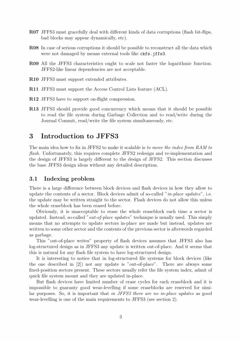
R07 JFFS3 must gracefully deal with different kinds of data corruptions (flash bit-flips,bad blocks may appear dynamically, etc).
R08 In case of serious corruptions it should be possible to reconstruct all the data whichwere not damaged by means external tools like ckfs.jffs3.
R09 All the JFFS3 characteristics ought to scale not faster the logarithmic function.JFFS2-like linear dependencies are not acceptable.
R10 JFFS3 must support extended attributes.
R11 JFFS3 must support the Access Control Lists feature (ACL).
R12 JFFS3 have to support on-flight compression.
R13 JFFS3 should provide good concurrency which means that it should be possibleto read the file system during Garbage Collection and to read/write during theJournal Commit, read/write the file system simultaneously, etc.
3 Introduction to JFFS3
The main idea how to fix in JFFS2 to make it scalable is to move the index from RAM toflash. Unfortunately, this requires complete JFFS2 redesign and re-implementation andthe design of JFFS3 is largely different to the design of JFFS2. This section discussesthe base JFFS3 design ideas without any detailed description.
3.1 Indexing problem
There is a large difference between block devices and flash devices in how they allow toupdate the contents of a sector. Block devices admit of so-called ”in-place updates”, i.e.the update may be written straight to the sector. Flash devices do not allow this unlessthe whole eraseblock has been erased before.
Obviously, it is unacceptable to erase the whole eraseblock each time a sector isupdated. Instead, so-called ”out-of-place updates” technique is usually used. This simplymeans that no attempts to update sectors in-place are made but instead, updates arewritten to some other sector and the contents of the previous sector is afterwords regardedas garbage.
This ”out-of-place writes” property of flash devices assumes that JFFS3 also haslog-structured design as in JFFS3 any update is written out-of-place. And it seems thatthis is natural for any flash file system to have log-structured design.
It is interesting to notice that in log-structured file systems for block devices (likethe one described in [2]) not any update is ”out-of-place”. There are always somefixed-position sectors present. These sectors usually refer the file system index, admit ofquick file system mount and they are updated in-place.
But flash devices have limited number of erase cycles for each eraseblock and it isimpossible to guaranty good wear-levelling if some eraseblocks are reserved for simi-lar purposes. So, it is important that in JFFS3 there are no in-place updates as goodwear-levelling is one of the main requirements to JFFS3 (see section 2).
3

The ”out-of-place updates” property makes it difficult to maintain the index on theflash media. Figure 1 demonstrates why.
A
B
C
D
Flash
A B C D D1
D1
Figure 1: JFFS3 indexing problem example.
Suppose the index is kept and maintained on flash and it consists of 4 parts A, B,C, and D which refer each other: A refers B and C, B refers D, and C refers D. Thismeans, that A contains the physical flash address of B and C and so on.
Suppose D should be updated. Since it is updated out-of-place, the newer versionD1 is written to some other place. But there are B and C which still refer D, not D1,and they ought to be updated as well. And when they are updated out-of-place, A willstill refer the old B and C, and so on. Thus, it is not that trivial to store and maintainindexing information on the flash media.
3.2 Wandering trees
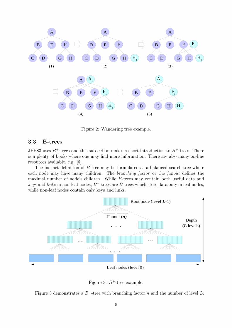
To address the above problem it is possible to use wandering trees. Figure 2 demonstrateshow do wandering trees work.
1. Suppose that the index is a tree and it is stored and maintained on the flash media.The tree consists of nodes A, B, C, D, E, F , G, and H. Suppose node H shouldbe updated.
2. At first, the updated version H1 is written. Obviously, F still refers H.
3. Now the corresponding link in node F is changed and node F1 is written to flash.F1 refers H1. But as F1 is also written out-of-place, A still refers the old node F .
4. Finally, the new root node A1 is written ant it refers F1.
5. Nodes A, F , H are now treated as garbage and the updated tree is composed bynodes A1, B, C, D, E, F1, G, and H1.
So, wandering trees is the base idea of how the indexing information is going to bemaintained on the flash media in JFFS3. And it stands to reason that any tree maybe called ”wandering tree” if any update in the tree requires updating parent nodes upto the root. For example, it makes sense to talk about wandering Red-Black trees orwandering B+-trees and so forth.
4
A
B E F
C D G H
(1)
A
B E F
C D G H
(2)
H1
A
B E F
C D G H
(3)
H1
F1
A
B E F
C D G H
(4)
H1
F1
A1
B E
C D G H
(5)
H1
F1
A1
Figure 2: Wandering tree example.
3.3 B-trees
JFFS3 uses B+-trees and this subsection makes a short introduction to B+-trees. Thereis a plenty of books where one may find more information. There are also many on-lineresources available, e.g. [6].
The inexact definition of B-tree may be formulated as a balanced search tree whereeach node may have many children. The branching factor or the fanout defines themaximal number of node’s children. While B-trees may contain both useful data andkeys and links in non-leaf nodes, B+-trees are B-trees which store data only in leaf nodes,while non-leaf nodes contain only keys and links.
. . .
... ...
. . .
Fanout (n)
Leaf nodes (level 0)
Depth(L levels)
Root node (level L-1)
Figure 3: B+-tree example.
Figure 3 demonstrates a B+-tree with branching factor n and the number of level L.
5
Note, that in JFFS3 levels are numbered starting from leaf nodes (level 0) and endingat the root node (level L− 1).
Leaf nodes in the B+-tree contain data which are indexed by keys. Non-leaf nodes donot contain data, but contain only the indexing information, namely, keys and links.
...
Link 2
Link 3
Link n
Keys < Key 1
Keys > Key 1 and ≤ Key 2
≥Keys Key n-1
Link n-1
Link 1
Key 1
Key 2
Key 3
Key n-1
Keys > Key 2 and ≤ Key 3
Keys > Key n-2 and ≤ Key n-1
Figure 4: The structure of a non-leaf node in B+-tree.
Figure 4 depicts the structure of a non-leaf node. There are n links and n − 1 keysin the node. Links may point to either leaf nodes or other non-leaf nodes. In the formercase, the leaf node will contain data which corresponds to the key which follows the link.In the latter case, the pointed non-leaf node (and the whole subtree with the root in thisnon-leaf node) will contain more keys in range (Key 1, Key 2].
Keys are sorted in the ascending order in non-leaf nodes, so it is not that difficultto lookup data corresponding to any key. Furthermore, the tree is balanced, so the thenumber of lookup steps does not depend on the key.
When objects are inserted or removed from the tree, re-balancing may be needed. Thetree is re-balanced by means of splitting nodes or merging them and there is a simpleenough algorithm exists. Please, refer to Donald Knuth’s books for more informationabout re-balancing B+-trees.
B+-trees are widely used when working with block devices (e.g., hard drives). Indeed,these devices have a fixed input/output unit size (usually referred to as a sector) and itis natural to use B+-trees with node size multiple to the size of the sector in order tostore information on such devices.
3.4 Indexing in JFFS3
The way how JFFS3 stores and indexes the file system is similar to the approach usedby the Reiser4 file system (see [5]). All the file system objects (inodes, files, directoryentries, extended attributes, etc) are kept in one large B+-tree. Effectively, the wholeJFFS3 file system may be regarded as one large B+-tree. This tree is further referred tojust as ”the tree”.
Every object which is stored in the tree has a key, and objects are found in the treeby their keys. To make it clearer what are object keys, the following is an example ofhow they may look like:
6
• file data key: {inode number, offset};
• directory entry key: {parent directory inode number, direntry name hash}and the like.
The following are terms which are used in JFFS3 to refer nodes of different levels inthe tree:
• nodes of level 0 are leaf nodes ;
• nodes of level 1 are twig nodes ;
• nodes which are not the root, not leaf, and not twig are branch nodes ;
• no-leaf nodes (i.e., the root, branch and twig) are indexing nodes.
Note, the same terminology (except indexing nodes) is used in the Reiser4 file sys-tem [5].
Non-leaf nodes are called ”indexing nodes” because they contain only indexing infor-mation, nothing else. No file system data is kept in the indexing nodes. Indexing nodeshave fixed size which is equivalent to the flash sector size.
It is important to note that somewhat unusual terminology is used in this document.The smallest input/output unit of the flash chip is called a sector. Since JFFS3 mainlyorients to NAND flashes, the sector is mostly the NAND page and is either 512 bytesor 2 Kilobytes. For other flash types the sector may be different. If flash’s minimalinput/output unit is very small (say, one bit as in case of NOR flash), there should be alayer which emulates larger sectors (say, 512 bytes).
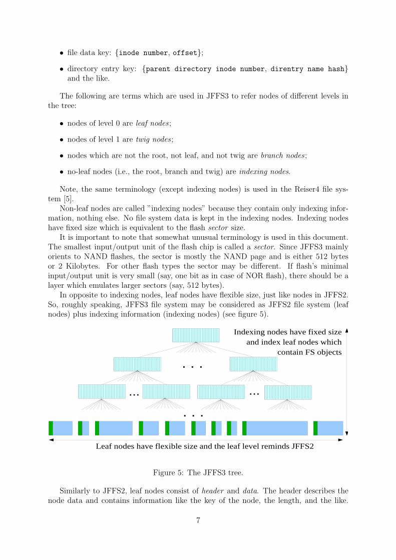
In opposite to indexing nodes, leaf nodes have flexible size, just like nodes in JFFS2.So, roughly speaking, JFFS3 file system may be considered as JFFS2 file system (leafnodes) plus indexing information (indexing nodes) (see figure 5).
. . .
... ...
. . .
Leaf nodes have flexible size and the leaf level reminds JFFS2
Indexing nodes have fixed sizeand index leaf nodes which
contain FS objects
Figure 5: The JFFS3 tree.
Similarly to JFFS2, leaf nodes consist of header and data. The header describes thenode data and contains information like the key of the node, the length, and the like.
7
Node data contains some file system data, for example a directory entry, file’s contents,etc.
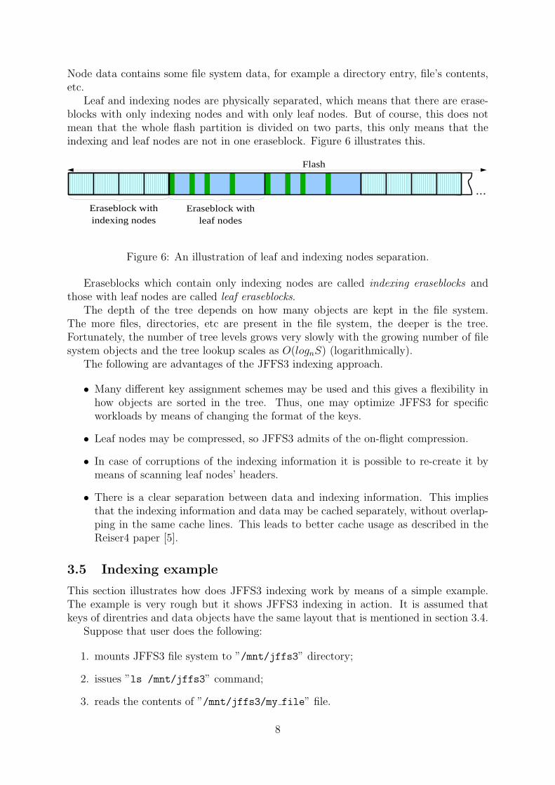
Leaf and indexing nodes are physically separated, which means that there are erase-blocks with only indexing nodes and with only leaf nodes. But of course, this does notmean that the whole flash partition is divided on two parts, this only means that theindexing and leaf nodes are not in one eraseblock. Figure 6 illustrates this.
...
Eraseblock with indexing nodes
Eraseblock with leaf nodes
Flash
Figure 6: An illustration of leaf and indexing nodes separation.
Eraseblocks which contain only indexing nodes are called indexing eraseblocks andthose with leaf nodes are called leaf eraseblocks.
The depth of the tree depends on how many objects are kept in the file system.The more files, directories, etc are present in the file system, the deeper is the tree.Fortunately, the number of tree levels grows very slowly with the growing number of filesystem objects and the tree lookup scales as O(lognS) (logarithmically).
The following are advantages of the JFFS3 indexing approach.
• Many different key assignment schemes may be used and this gives a flexibility inhow objects are sorted in the tree. Thus, one may optimize JFFS3 for specificworkloads by means of changing the format of the keys.
• Leaf nodes may be compressed, so JFFS3 admits of the on-flight compression.
• In case of corruptions of the indexing information it is possible to re-create it bymeans of scanning leaf nodes’ headers.
• There is a clear separation between data and indexing information. This impliesthat the indexing information and data may be cached separately, without overlap-ping in the same cache lines. This leads to better cache usage as described in theReiser4 paper [5].
3.5 Indexing example
This section illustrates how does JFFS3 indexing work by means of a simple example.The example is very rough but it shows JFFS3 indexing in action. It is assumed thatkeys of direntries and data objects have the same layout that is mentioned in section 3.4.
Suppose that user does the following:
1. mounts JFFS3 file system to ”/mnt/jffs3” directory;
2. issues ”ls /mnt/jffs3” command;
3. reads the contents of ”/mnt/jffs3/my file” file.
8
The following are comments about what is going on in JFFS3 during the above steps.
1. During mount JFFS3 locates the position of the root node. This is done with helpof the JFFS3 superblock which will be described later (see section 6).
2. To get the list of directory entries in the root directory, JFFS3 looks up all objectsmatching the {2, ∗} key pattern. Indeed, direntry keys have {parent inode #, name hash}format, the root directory inode number is 2 (or another predefined constant). ∗”means wildcard. Thus, JFFS3, {2, ∗} will match to any direntry in the root direc-tory.
3. To read the ”my file” file, JFFS3 first needs to find out its inode number. Theinode number is stored in the directory entry object. Hence, JFFS3 reads my file’sdirentry using {1, H("my file")} key (H() is the hash function).
Then JFFS3 searches for my file’s data objects using {I, offset} keys. Dependingon which part of file should be read, offset may take different values.
The above description is somewhat simplified e.g., JFFS3 also needs to read my file’sattr-data object to fetch the inode length from there (see section 4.1), etc. But the aimof the section is just to provide an idea of how JFFS3 indexing works.
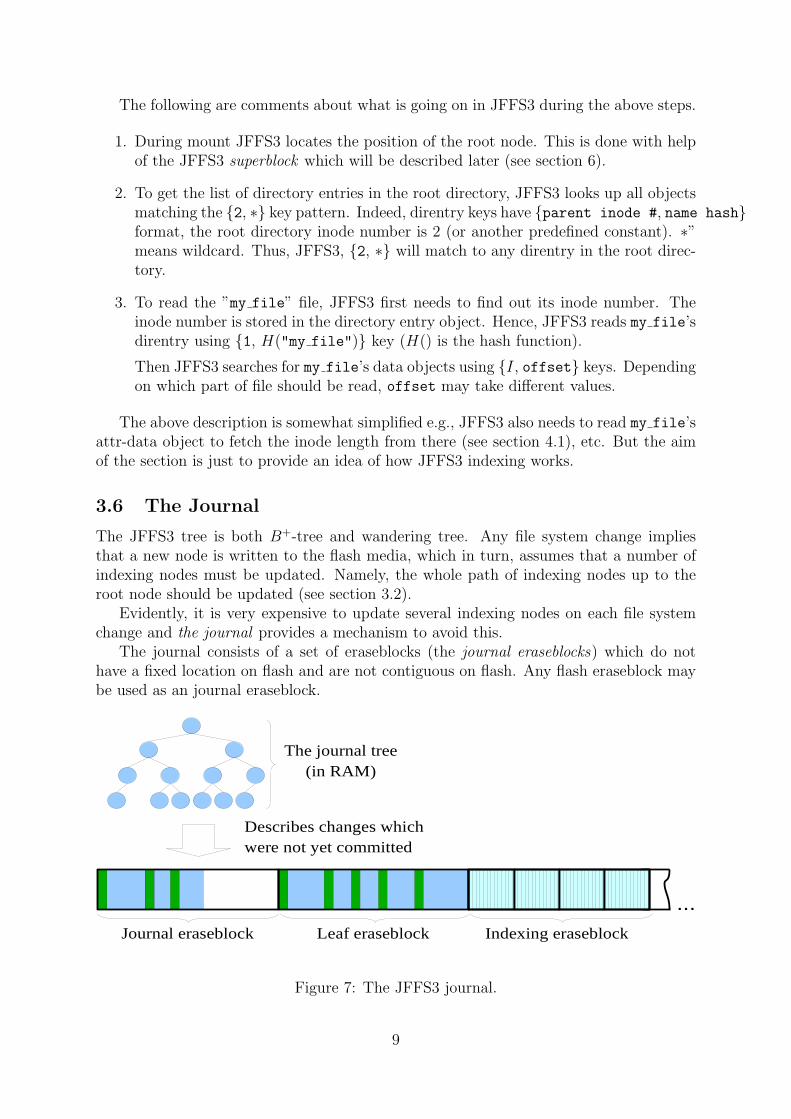
3.6 The Journal
The JFFS3 tree is both B+-tree and wandering tree. Any file system change impliesthat a new node is written to the flash media, which in turn, assumes that a number ofindexing nodes must be updated. Namely, the whole path of indexing nodes up to theroot node should be updated (see section 3.2).
Evidently, it is very expensive to update several indexing nodes on each file systemchange and the journal provides a mechanism to avoid this.
The journal consists of a set of eraseblocks (the journal eraseblocks) which do nothave a fixed location on flash and are not contiguous on flash. Any flash eraseblock maybe used as an journal eraseblock.
...Journal eraseblock Leaf eraseblock Indexing eraseblock
The journal tree (in RAM)
Describes changes which were not yet committed
Figure 7: The JFFS3 journal.
9
When something is changed in the JFFS3 file system, the corresponding leaf node iswritten to the journal, but the corresponding indexing nodes are not updated. Instead,JFFS3 keeps track of file system changes in RAM in a data structure called the journaltree (see figure 7).
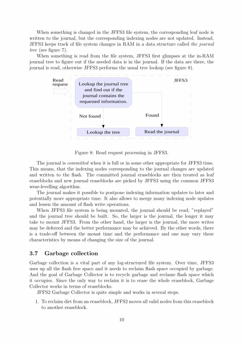
When something is read from the file system, JFFS3 first glimpses at the in-RAMjournal tree to figure out if the needed data is in the journal. If the data are there, thejournal is read, otherwise JFFS3 performs the usual tree lookup (see figure 8).
Lookup the journal treeand find out if the
journal contains therequested information.
Lookup the tree
Found
Read the journal
Not found
Read request
JFFS3
Figure 8: Read request processing in JFFS3.
The journal is committed when it is full or in some other appropriate for JFFS3 time.This means, that the indexing nodes corresponding to the journal changes are updatedand written to the flash. The committed journal eraseblocks are then treated as leaferaseblocks and new journal eraseblocks are picked by JFFS3 using the common JFFS3wear-levelling algorithm.
The journal makes it possible to postpone indexing information updates to later andpotentially more appropriate time. It also allows to merge many indexing node updatesand lessen the amount of flash write operations.
When JFFS3 file system is being mounted, the journal should be read, ”replayed”and the journal tree should be built. So, the larger is the journal, the longer it maytake to mount JFFS3. From the other hand, the larger is the journal, the more writesmay be deferred and the better performance may be achieved. By the other words, thereis a trade-off between the mount time and the performance and one may vary thesecharacteristics by means of changing the size of the journal.
3.7 Garbage collection
Garbage collection is a vital part of any log-structured file system. Over time, JFFS3uses up all the flash free space and it needs to reclaim flash space occupied by garbage.And the goal of Garbage Collector is to recycle garbage and reclame flash space whichit occupies. Since the only way to reclaim it is to erase the whole eraseblock, GarbageCollector works in terms of eraseblocks.
JFFS2 Garbage Collector is quite simple and works in several steps.
1. To reclaim dirt from an eraseblock, JFFS2 moves all valid nodes from this eraseblockto another eraseblock.
10
2. As nodes have changed their positions, the JFFS2 in-RAM index is adjusted.
3. The first eraseblock may be erased and re-used.
Note, JFFS2 (and JFFS3) aways reserves several eraseblocks in order to guaranteethat there are always some free eraseblocks available to perform garbage collection.
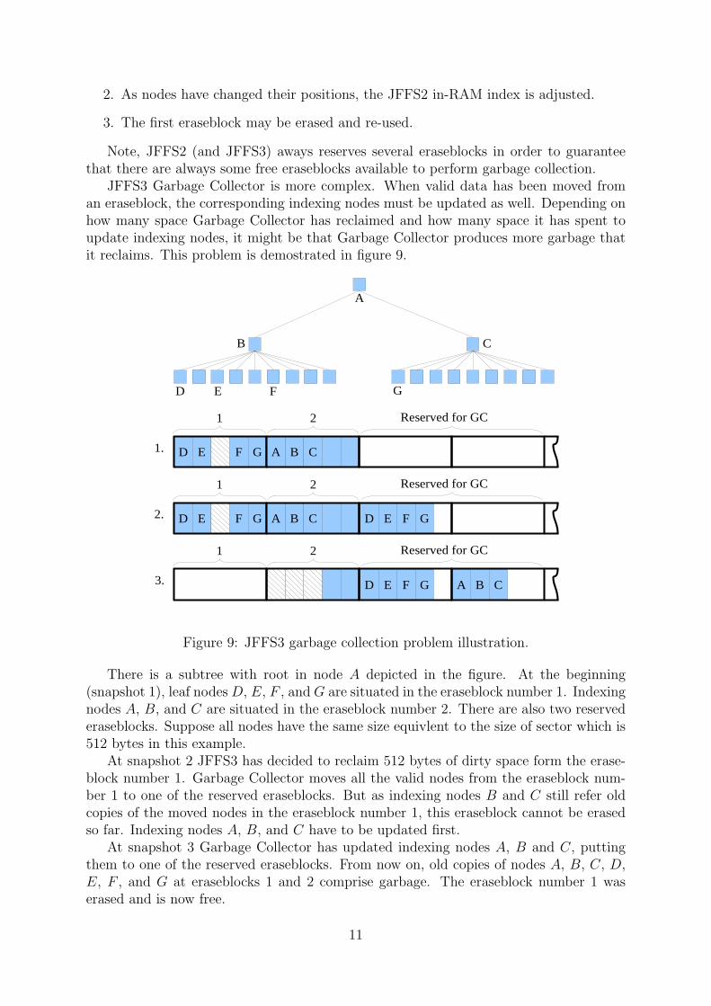
JFFS3 Garbage Collector is more complex. When valid data has been moved froman eraseblock, the corresponding indexing nodes must be updated as well. Depending onhow many space Garbage Collector has reclaimed and how many space it has spent toupdate indexing nodes, it might be that Garbage Collector produces more garbage thatit reclaims. This problem is demostrated in figure 9.
B CA
D E F G
A
B C
D E F G B CA
D E F G
1 2 Reserved for GC
D E F G B CA
1 2 Reserved for GC
D E F G
1 2 Reserved for GC
1.
2.
3.
Figure 9: JFFS3 garbage collection problem illustration.
There is a subtree with root in node A depicted in the figure. At the beginning(snapshot 1), leaf nodes D, E, F , and G are situated in the eraseblock number 1. Indexingnodes A, B, and C are situated in the eraseblock number 2. There are also two reservederaseblocks. Suppose all nodes have the same size equivlent to the size of sector which is512 bytes in this example.
At snapshot 2 JFFS3 has decided to reclaim 512 bytes of dirty space form the erase-block number 1. Garbage Collector moves all the valid nodes from the eraseblock num-ber 1 to one of the reserved eraseblocks. But as indexing nodes B and C still refer oldcopies of the moved nodes in the eraseblock number 1, this eraseblock cannot be erasedso far. Indexing nodes A, B, and C have to be updated first.
At snapshot 3 Garbage Collector has updated indexing nodes A, B and C, puttingthem to one of the reserved eraseblocks. From now on, old copies of nodes A, B, C, D,E, F , and G at eraseblocks 1 and 2 comprise garbage. The eraseblock number 1 waserased and is now free.
11
But unfortunatelly, the result is that Garbage Collector made more dirt that it re-claimed space. Indeed, GC reclaimed 512 bytes while produced three times greateramount of garbage (see the first three sectors at eraseblock 2, snapshot 3). Comparesnapshots 1 and 2.
Hence, it is obvious that garbage collection in JFFS3 is must be more complex thatin JFFS2. Chapter 5 discusses JFFS3 Garbage Collector in details.
3.8 The superblock
The JFFS3 superblock is a data structure that describes the file system as a whole andcontains important information like the offset of the root node, the journal eraseblocks,etc. When the file system is being mounted, it first finds and reads the JFFS3 superblock.
In case of traditional file systems the superblock usually resides at a fixed positionon the disk and may be found very quickly. Conversely, due to the ”out-of-place write”flash property it is impossible to assign a fixed position for the JFFS3 superblock. Thingsare getting even more complex because of the need to provide good wear-levelling – it isincorrect to just reserve several erasable blocks for the superblock unless it is guaranteedthat these eraseblocks will not be worn out earlier then the other eraseblocks.
We have the following two requirements that ought to be met in JFFS3:
• JFFS3 must be able to quickly find the superblock;
• the superblock management techniques must not spoil the overall flash wear level-ling.
In the classical file systems the superblock usually contains a lot of static data whichis rarely updated and the superblock may have any size. In JFFS3, the superblock mustbe updated quite often (e.g., each time the journal is committed). This means that tolessen the amount of I/O, the JFFS3 superblock should be as small as it is possible,namely, one sector. And there is no reason to keep any static data in the superblock(e.g., the size of the file system, its version, etc). For static data, JFFS3 reserves the firsteraseblock of the JFFS3 partition.
Thus, the following terms are used in this document:
• static superblock – contains only static data which are never changed by JFFS3; thestatic superblock resides at the static eraseblock ; the static eraseblock is the firstnon-bad eraseblock of the JFFS3 partition; it is supposed that the contents of thestatic eraseblock may only be changed by external user-level tools;
• superblock – contains only dynamic data, is changed quite often and requires specialmethods to deal with.
JFFS3 has a rather complicated superblock management scheme which makes it pos-sible to quickly find the superblock without full flash scanning when the file system isbeing mounted. This scheme provides good flash wear-levelling. The superblock lookupshould take few milliseconds and scale as O(log2(S)). For more detailed informationabout the superblock management scheme see section 6.1.
12
4 The tree
This chapter discusses the all the aspects related to the main JFFS3 entity – the tree.Please, refer to section 3.4 for basic information about the JFFS3 tree.
4.1 Objects
JFFS3 keeps file system objects in the leaf level of the tree (in leaf nodes) and the followingis the list of supported objects.
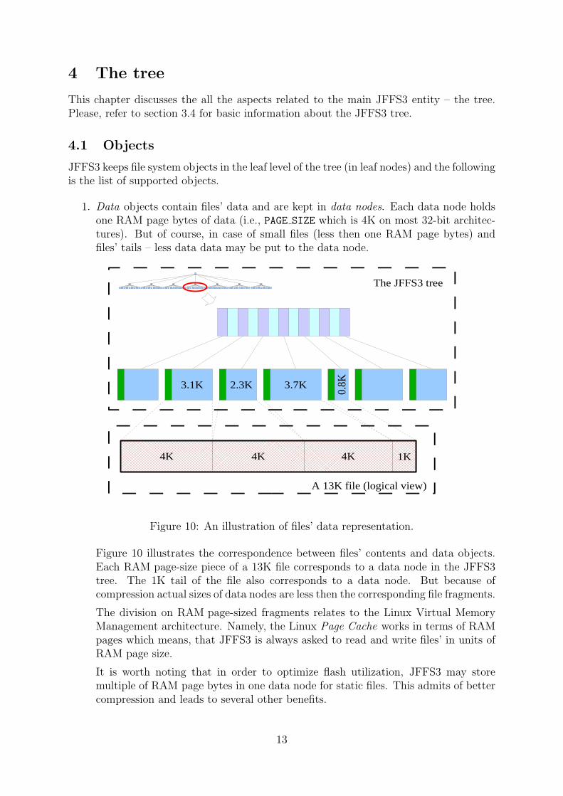
1. Data objects contain files’ data and are kept in data nodes. Each data node holdsone RAM page bytes of data (i.e., PAGE SIZE which is 4K on most 32-bit architec-tures). But of course, in case of small files (less then one RAM page bytes) andfiles’ tails – less data data may be put to the data node.
3.1K
4K 4K 4K 1K
2.3K 3.7K
0.8K
A 13K file (logical view)
The JFFS3 tree
Figure 10: An illustration of files’ data representation.
Figure 10 illustrates the correspondence between files’ contents and data objects.Each RAM page-size piece of a 13K file corresponds to a data node in the JFFS3tree. The 1K tail of the file also corresponds to a data node. But because ofcompression actual sizes of data nodes are less then the corresponding file fragments.
The division on RAM page-sized fragments relates to the Linux Virtual MemoryManagement architecture. Namely, the Linux Page Cache works in terms of RAMpages which means, that JFFS3 is always asked to read and write files’ in units ofRAM page size.
It is worth noting that in order to optimize flash utilization, JFFS3 may storemultiple of RAM page bytes in one data node for static files. This admits of bettercompression and leads to several other benefits.
13
2. Direntry objects contain the correspondence between directory entry names andinode numbers. Direntry objects are stored in direntry nodes. Every directoryentry in the file system has a corresponding direntry object.
3. Attr-data objects contain attributes of inodes – both standard Unix attributes likeuser ID, last modification time, inode length, etc and JFFS3-specific attributes likethe type of compression, etc. Each inode has only one corresponding attr-dataobject.
4. Xentry objects contain the correspondence between names of extended attributesand xattr IDs. Every extended attribute in the file system has a correspondingxattr entry object. This is analogous to direntry objects, but direntries contain{direntry name⇒inode number} mapping, instead of {xattr name⇒xattr ID}mapping in xentries.
Each extended attribute in JFFS3 has its own unique number – xattr ID, just likeevery inode has its own unique inode number. And in fact, JFFS3 utilizes the samespace of numbers to enumerate inodes and extended attributes.
Xentry objects are stored in xentry nodes.
5. Xattr-data objects contain the data of extended attributes. The way how xattr-dataobjects are kept in the tree is equivalent to the way how data objects a kept there.Xattr-data objects are stored in xattr-data nodes.
6. Acl objects contain Access Control Lists (ACL) of inodes (information about ACLsmay be found out at [7]). Acl objects are stored in acl nodes.
In real-world systems a vast number of files have equivalent ACL while only fewfiles have unique ACL. For the former group of files (or more strictly – inodes)JFFS3 makes use of shared acl objects. This means, that there is only one aclobject instance for all of these inodes. Shared acls are referred to from attr-dataobjects of these inodes. If a shared acl is written to, a new acl object is created(copy-on-write mechanism). Conversely, for the latter group there is a distinct aclobject per each inode.
4.2 Keys
Each object has its own key and may be quickly looked up in the tree by its key. Asthere are 6 object types in JFFS3, there are also 6 key types:
1. data keys – index data objects;
2. direntry keys – index direntry objects;
3. attr-data keys – index attr-data objects;
4. xentry keys – index xentry objects;
5. xattr-data keys – index xattr-data objects;
6. acl keys – index acl objects.
14
4.2.1 Trivial key scheme
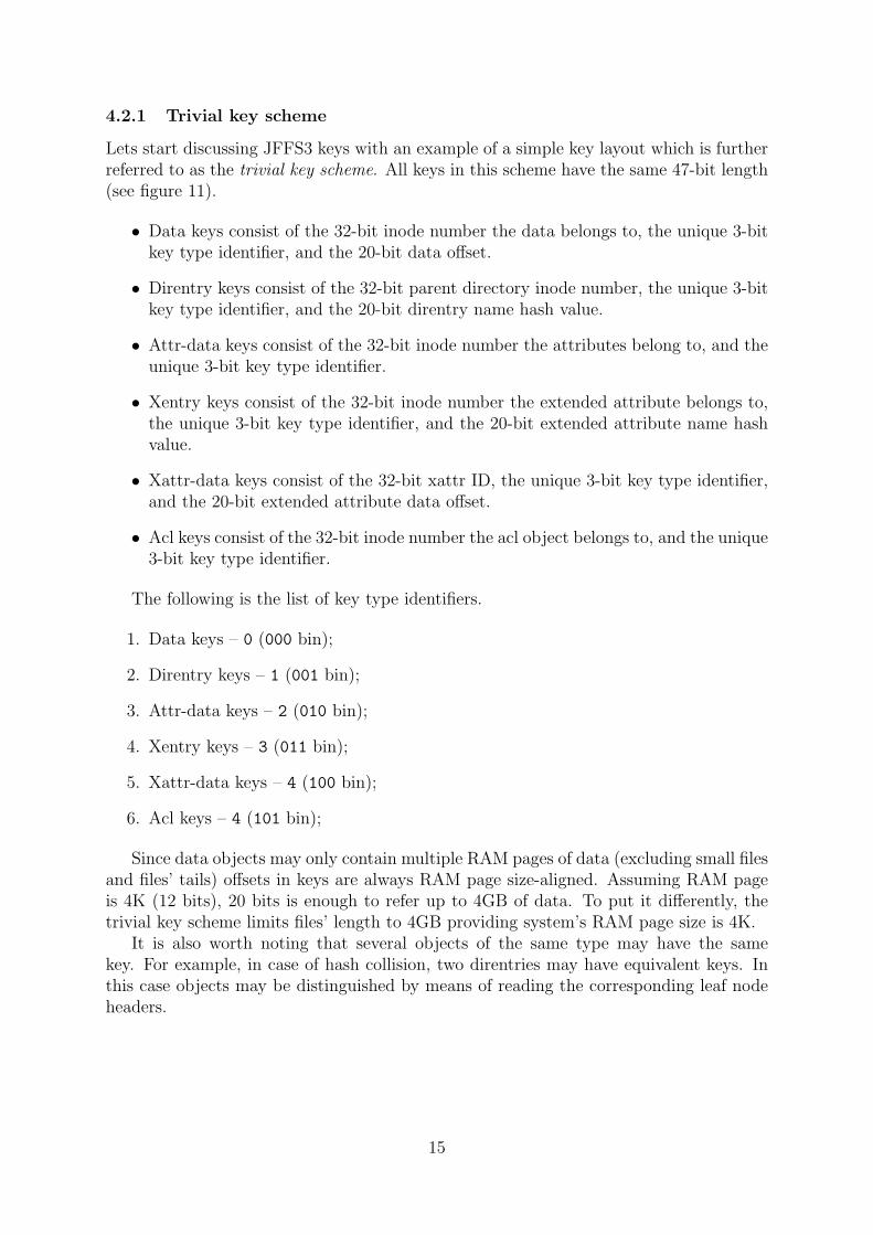
Lets start discussing JFFS3 keys with an example of a simple key layout which is furtherreferred to as the trivial key scheme. All keys in this scheme have the same 47-bit length(see figure 11).
• Data keys consist of the 32-bit inode number the data belongs to, the unique 3-bitkey type identifier, and the 20-bit data offset.
• Direntry keys consist of the 32-bit parent directory inode number, the unique 3-bitkey type identifier, and the 20-bit direntry name hash value.
• Attr-data keys consist of the 32-bit inode number the attributes belong to, and theunique 3-bit key type identifier.
• Xentry keys consist of the 32-bit inode number the extended attribute belongs to,the unique 3-bit key type identifier, and the 20-bit extended attribute name hashvalue.
• Xattr-data keys consist of the 32-bit xattr ID, the unique 3-bit key type identifier,and the 20-bit extended attribute data offset.
• Acl keys consist of the 32-bit inode number the acl object belongs to, and the unique3-bit key type identifier.
The following is the list of key type identifiers.
1. Data keys – 0 (000 bin);
2. Direntry keys – 1 (001 bin);
3. Attr-data keys – 2 (010 bin);
4. Xentry keys – 3 (011 bin);
5. Xattr-data keys – 4 (100 bin);
6. Acl keys – 4 (101 bin);
Since data objects may only contain multiple RAM pages of data (excluding small filesand files’ tails) offsets in keys are always RAM page size-aligned. Assuming RAM pageis 4K (12 bits), 20 bits is enough to refer up to 4GB of data. To put it differently, thetrivial key scheme limits files’ length to 4GB providing system’s RAM page size is 4K.
It is also worth noting that several objects of the same type may have the samekey. For example, in case of hash collision, two direntries may have equivalent keys. Inthis case objects may be distinguished by means of reading the corresponding leaf nodeheaders.
15

inode # (32) type (3) offset (20)
parent inode # (32) type (3) name hash (20)
inode # (32) type (3) offset (20)
inode # (32) type (3) name hash (20)
xattr ID (32) type (3) offset (20)
inode # (32) type (3) unused (20)
data key:
direntry key:
attr-data key:
xentry key:
xattr-data key:
acl key:
Figure 11: The trivial key scheme.
4.2.2 Keys comparison
The important topic is how keys are compared as it defines the relative order of objectsin the tree and is crucial for searching. Note, it only makes sense to compare keys of thesame type.
JFFS3 keys are usually comprised of one or more fields, i.e., keys K1 and K2 may berepresented as
K1 = {k11, k
21, ..., k
p1}, K2 = {k1
2, k22, ..., k
p2},
where p is the number of components in keys of this type.Keys K1 and K2 are considered to be equivalent if and only if all their fields are
equivalent, i.e. ki1 = ki
2, i = 1, 2, ..., p.Keys are compared field-by-field starting from the first field. If on i’th step ki
1 > ki2,
then K1 is considered to be greater then K2. Similarly, if on i’th step ki1 < ki
2, then K1
is considered to be less then K2.
4.2.3 Key schemes
Key schemes define layout of keys for all the 6 object types. Apparently, it would be tooinflexible to hardcode JFFS3 to support only one fixed key scheme. Indeed, there maybe a great deal of reasons why users may want to use different key schemes in differentsituations – some examples go bellow.
• The inode number is encoded by a 32-bit integer in the trivial key scheme whichmeans that about 4 million inodes and extended attributes may exist on the filesystem simultaneously. But in some cases this may be insufficient or, conversely,too much and one may want to use less bits to encode inode numbers (say, only 24bits), just for optimization.
16
• Similarly, offsets are encoded as 20-bit integers in the trivial key scheme which maybe insufficient when huge files (larger then 4G) should be supported. So one maywant to use more bits in certain cases.
• Depending on the concrete JFFS3 usage, different hash functions may be used indirentry keys. The length of hash values may also vary depending on how manydirectory entries are kept in directories. If there are huge directories with millionsof files there, long hash values should be used to avoid massive hash collisions (say,64-bit hash values). But if it is known in advance that there will be no too largedirectory entries, 2 the length of hash values may be shorter.
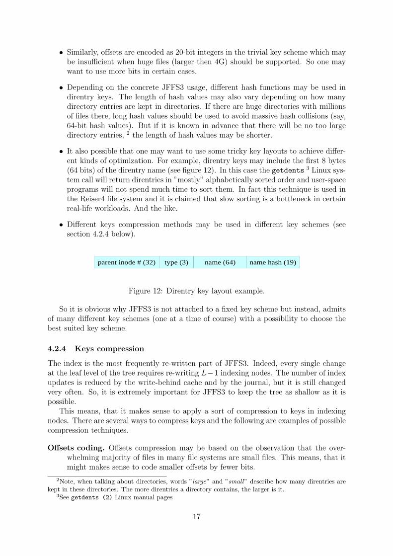
• It also possible that one may want to use some tricky key layouts to achieve differ-ent kinds of optimization. For example, direntry keys may include the first 8 bytes(64 bits) of the direntry name (see figure 12). In this case the getdents 3 Linux sys-tem call will return direntries in ”mostly” alphabetically sorted order and user-spaceprograms will not spend much time to sort them. In fact this technique is used inthe Reiser4 file system and it is claimed that slow sorting is a bottleneck in certainreal-life workloads. And the like.
• Different keys compression methods may be used in different key schemes (seesection 4.2.4 below).
parent inode # (32) type (3) name (64) name hash (19)
Figure 12: Direntry key layout example.
So it is obvious why JFFS3 is not attached to a fixed key scheme but instead, admitsof many different key schemes (one at a time of course) with a possibility to choose thebest suited key scheme.
4.2.4 Keys compression
The index is the most frequently re-written part of JFFS3. Indeed, every single changeat the leaf level of the tree requires re-writing L−1 indexing nodes. The number of indexupdates is reduced by the write-behind cache and by the journal, but it is still changedvery often. So, it is extremely important for JFFS3 to keep the tree as shallow as it ispossible.
This means, that it makes sense to apply a sort of compression to keys in indexingnodes. There are several ways to compress keys and the following are examples of possiblecompression techniques.
Offsets coding. Offsets compression may be based on the observation that the over-whelming majority of files in many file systems are small files. This means, that itmight makes sense to code smaller offsets by fewer bits.
2Note, when talking about directories, words ”large” and ”small” describe how many direntries arekept in these directories. The more direntries a directory contains, the larger is it.
3See getdents (2) Linux manual pages
17
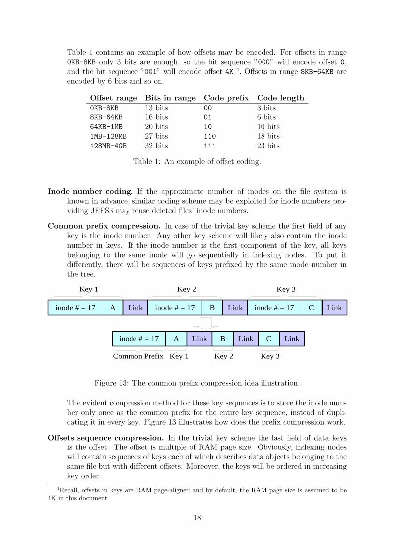
Table 1 contains an example of how offsets may be encoded. For offsets in range0KB-8KB only 3 bits are enough, so the bit sequence ”000” will encode offset 0,and the bit sequence ”001” will encode offset 4K 4. Offsets in range 8KB-64KB areencoded by 6 bits and so on.
Offset range Bits in range Code prefix Code length0KB-8KB 13 bits 00 3 bits8KB-64KB 16 bits 01 6 bits64KB-1MB 20 bits 10 10 bits1MB-128MB 27 bits 110 18 bits128MB-4GB 32 bits 111 23 bits
Table 1: An example of offset coding.
Inode number coding. If the approximate number of inodes on the file system isknown in advance, similar coding scheme may be exploited for inode numbers pro-viding JFFS3 may reuse deleted files’ inode numbers.
Common prefix compression. In case of the trivial key scheme the first field of anykey is the inode number. Any other key scheme will likely also contain the inodenumber in keys. If the inode number is the first component of the key, all keysbelonging to the same inode will go sequentially in indexing nodes. To put itdifferently, there will be sequences of keys prefixed by the same inode number inthe tree.
inode # = 17 A
inode # = 17
Link inode # = 17 B Link inode # = 17 C Link
A Link B Link C Link
Key 1 Key 2 Key 3
Key 1 Key 2 Key 3Common Prefix
Figure 13: The common prefix compression idea illustration.
The evident compression method for these key sequences is to store the inode num-ber only once as the common prefix for the entire key sequence, instead of dupli-cating it in every key. Figure 13 illustrates how does the prefix compression work.
Offsets sequence compression. In the trivial key scheme the last field of data keysis the offset. The offset is multiple of RAM page size. Obviously, indexing nodeswill contain sequences of keys each of which describes data objects belonging to thesame file but with different offsets. Moreover, the keys will be ordered in increasingkey order.
4Recall, offsets in keys are RAM page-aligned and by default, the RAM page size is assumed to be4K in this document
18

For sequences like this it is possible to only specify the starting offset, the endingoffset and the number of keys in the sequence, instead of wasting space storing theoffset in each key of the sequence.
0K 12K 4 A Link B Link C Link D Link
Key 1 Key 2 Key 3 Key 4
Start End Count Key1 Key2 Key3 Key4
0K LinkA 4K LinkB 8K LinkC 12K LinkA
Figure 14: The Offsets sequence compression idea illustration.
Figure 14 presents an example of the offsets sequence compression method. Fourconsecutive keys which describe four data objects belonging to the same inode maybe represented as a sequence of four keys without the offset field, but prefixed bythe starting offset, the ending offset and the number of keys in the sequence.
Note, the above compression methods may be combined to achieve better compression.Because of compression, JFFS3 keys have variable size which means, that it is im-
possible to directly apply the binary search algorithm to the contents of indexing nodes.In JFFS3, indexing nodes are decompressed when read and are cached in decompressedform. And after the indexing node has been decompressed, the binary search algorithmis applicable.
We believe that keys compression will considerably reduce the amount of on-flashindexing information and increase the overall performance just because the amount ofInput/Output will lessen. But only actual fixed-size keys vs. variable-size keys tests willshow if there is some real performance gain present.
4.3 Links
Links in JFFS3 have fixed length and are not compressed. The link width depends onthe size of JFFS3 partition – the larger is JFFS3 partition, the wider are links. Instead ofchoosing a huge link width to suit the largest possible file systems (e.g. 64 bits), JFFS3admits of flexible links width, depending on JFFS3 partition size.
As indexind nodes have fixed size equivalent to one sector, the width of links storedin branch nodes and in the root nodes is
w = log2S − s.
Twig nodes refer variable-size leaf nodes so the width of links stored twih nodes is
w = log2S,
where S is the size of the JFFS3 partition and s is the size of sector.
19
5 Garbage Collection
Note! JFFS3 Garbage Collection is currently under development and thischapter may be changed. Any suggestions and ideas are welcome.
6 The superblock
6.1 The superblock management algorithm
To implement the superblock management scheme, JFFS3 reserves the second and thethird good eraseblocks at the beginning of the flash partition (just next to the staticeraseblock). These two eraseblocks are called anchor eraseblocks, or the anchor area.
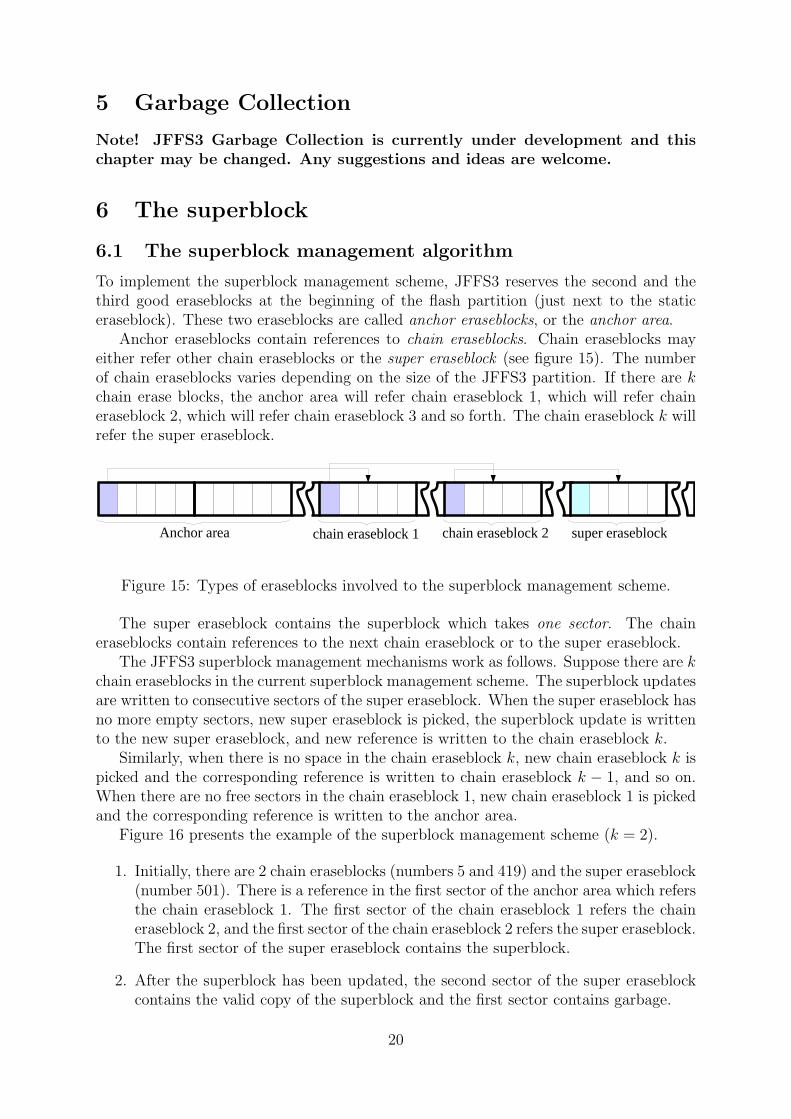
Anchor eraseblocks contain references to chain eraseblocks. Chain eraseblocks mayeither refer other chain eraseblocks or the super eraseblock (see figure 15). The numberof chain eraseblocks varies depending on the size of the JFFS3 partition. If there are kchain erase blocks, the anchor area will refer chain eraseblock 1, which will refer chaineraseblock 2, which will refer chain eraseblock 3 and so forth. The chain eraseblock k willrefer the super eraseblock.
Anchor area chain eraseblock 1 chain eraseblock 2 super eraseblock
Figure 15: Types of eraseblocks involved to the superblock management scheme.
The super eraseblock contains the superblock which takes one sector. The chaineraseblocks contain references to the next chain eraseblock or to the super eraseblock.
The JFFS3 superblock management mechanisms work as follows. Suppose there are kchain eraseblocks in the current superblock management scheme. The superblock updatesare written to consecutive sectors of the super eraseblock. When the super eraseblock hasno more empty sectors, new super eraseblock is picked, the superblock update is writtento the new super eraseblock, and new reference is written to the chain eraseblock k.
Similarly, when there is no space in the chain eraseblock k, new chain eraseblock k ispicked and the corresponding reference is written to chain eraseblock k − 1, and so on.When there are no free sectors in the chain eraseblock 1, new chain eraseblock 1 is pickedand the corresponding reference is written to the anchor area.
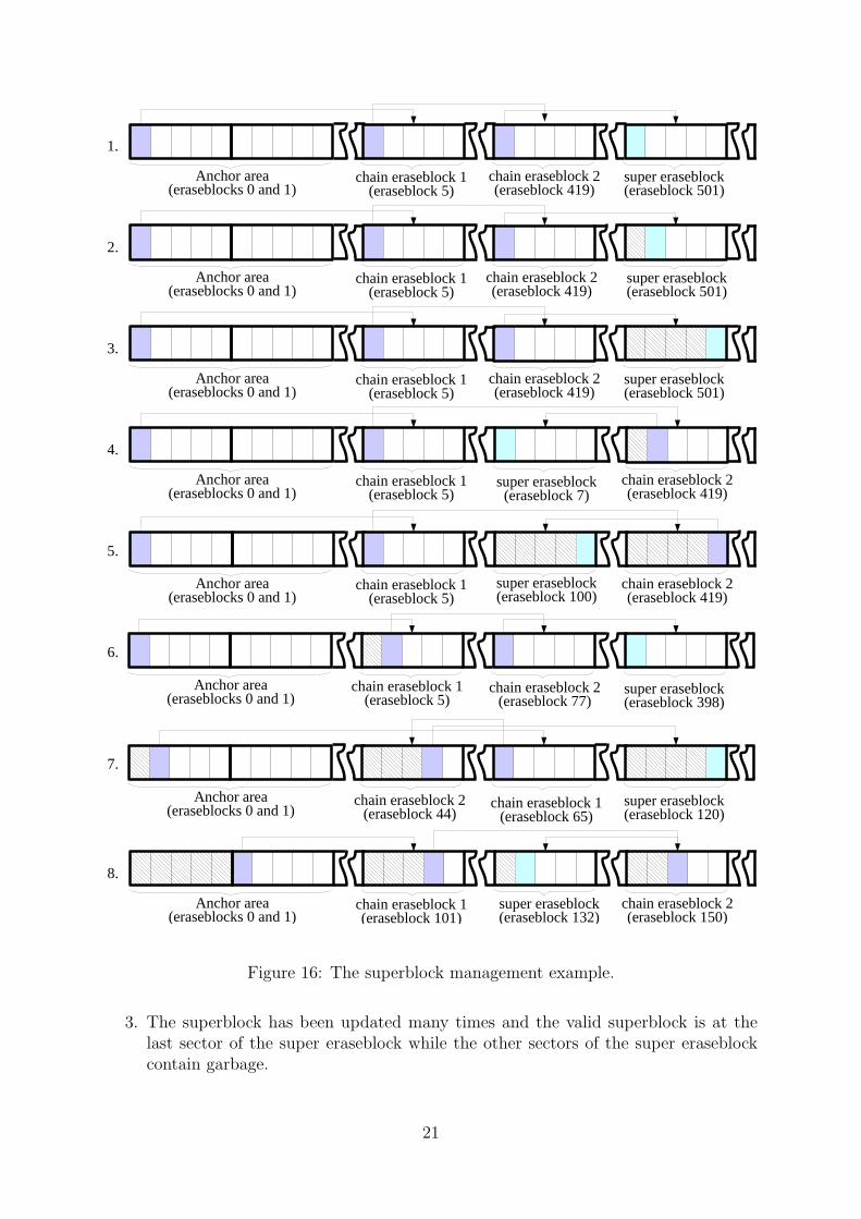
Figure 16 presents the example of the superblock management scheme (k = 2).
1. Initially, there are 2 chain eraseblocks (numbers 5 and 419) and the super eraseblock(number 501). There is a reference in the first sector of the anchor area which refersthe chain eraseblock 1. The first sector of the chain eraseblock 1 refers the chaineraseblock 2, and the first sector of the chain eraseblock 2 refers the super eraseblock.The first sector of the super eraseblock contains the superblock.
2. After the superblock has been updated, the second sector of the super eraseblockcontains the valid copy of the superblock and the first sector contains garbage.
20
Anchor area (eraseblocks 0 and 1)
chain eraseblock 1 (eraseblock 5)
chain eraseblock 2(eraseblock 419)
super eraseblock (eraseblock 501)
Anchor area (eraseblocks 0 and 1)
chain eraseblock 1 (eraseblock 5)
chain eraseblock 2(eraseblock 419)
super eraseblock (eraseblock 501)
Anchor area (eraseblocks 0 and 1)
chain eraseblock 1 (eraseblock 5)
chain eraseblock 2(eraseblock 419)
super eraseblock (eraseblock 501)
Anchor area (eraseblocks 0 and 1)
chain eraseblock 1 (eraseblock 5)
chain eraseblock 2(eraseblock 419)
super eraseblock (eraseblock 7)
Anchor area (eraseblocks 0 and 1)
chain eraseblock 1 (eraseblock 5)
chain eraseblock 2(eraseblock 419)
super eraseblock (eraseblock 100)
Anchor area (eraseblocks 0 and 1)
chain eraseblock 1 (eraseblock 5)
chain eraseblock 2(eraseblock 77)
super eraseblock (eraseblock 398)
Anchor area (eraseblocks 0 and 1) chain eraseblock 1
(eraseblock 65)chain eraseblock 2
(eraseblock 44)super eraseblock (eraseblock 120)
Anchor area (eraseblocks 0 and 1)
chain eraseblock 1 (eraseblock 101)
chain eraseblock 2(eraseblock 150)
super eraseblock (eraseblock 132)
1.
2.
3.
4.
5.
6.
7.
8.
Figure 16: The superblock management example.
3. The superblock has been updated many times and the valid superblock is at thelast sector of the super eraseblock while the other sectors of the super eraseblockcontain garbage.
21

4. As there were no free sectors at the super eraseblock, new super eraseblock waschosen (eraseblock number 7) and the superblock update was written to the firstsector of the new super eraseblock. As the super eraseblock changed its position,the corresponding reference at the chain eraseblock 2 was updated. It was updatedout-of-place and now the first sector of the chain eraseblock 2 is dirty while thesecond sector contains the valid reference to the new super eraseblock.
5. The superblock has been updated many times and the super eraseblock changedits position many times and it is currently at the eraseblock number 100. Thereference to the super eraseblock was also updated many times and at the momentthe last sector of the chain eraseblock 2 contains the valid reference while the othersectors are obsolete. Similarly, the last sector of the super eraseblock contains validsuperblock while the other sectors are obsolete.
6. When the next superblock update came, there were no free sectors at the supereraseblock and new super eraseblock was picked (eraseblock number 398) and thevalid copy of the superblock is currently at the first sector of the eraseblock num-ber 398, Also, there were no free sectors at the chain eraseblock 2 and new chaineraseblock 2 was picked (eraseblock number 77), so the first sector of the erase-block 77 contains the valid reference to the super eraseblock. Since the chain erase-block 2 changed its position, the corresponding reference at the chain eraseblock 1was updated and at the moment the second sector of the chain eraseblock 1 containsthe valid reference to the chain eraseblock 2 while the first sector is dirty.
7. And analogously, after many superblock updates, the chain eraseblock 1 was up-dated many times and when it became full it changed its position. Sure, the chaineraseblock 2 and the super eraseblock changed their positions many times as well.So, at the moment, the chain eraseblock 1 is at the eraseblock number 65, thechain eraseblock 2 is at the eraseblock 44 and the super eraseblock is at the erase-block 120. When the chain eraseblock 1 changed its position, the correspondingreference at the anchor area was updated and currently the second sector of theanchor eraseblock 1 contains the valid reference to the chain eraseblock 1 while thefirs sector is dirty.
8. And even more superblock updates happened. The anchor area was updated manytimes. When there were no free sectors at the anchor eraseblock 1, the anchoreraseblock 2 was used. So, at the moment, the valid reference to the chain erase-block 1 is at the first sector of the anchor eraseblock 2. From now on, the firstanchor eraseblock may be erased and may be used again when the second anchoreraseblock is full.
The following are important notes about the JFFS3 superblock management.
• The superblock takes one sector so the super eraseblock may be updated at mostN times (N is the number of sectors in the eraseblock).
• In case of NAND flash, the sector is the real minimal physical input/output unit, soonly N updates are possible in anchor eraseblocks and in chain eraseblocks. But ifthe real input/output unit is smaller then the sector (i.e., if JFFS3 works on top of
22

NOR flash) the advantage of this may be used and more references may be packedinto one anchor or chain eraseblock.
• When JFFS3 picks new chain/super eraseblock, the common JFFS3 wear-levellingscheme is utilized.
• Anchor area has 2 eraseblocks in order to ensure the tolerance to unclean reboots –one anchor eraseblock may be safely erased while the other is being used.
• When a new reference is written to anchor/chain eraseblocks, the previous referencebecomes dirty and on mount JFFS3 should find the valid reference. To facilitatethis, each reference has its version number. Each subsequent reference has higherversion then the previous. Hence, JFFS3 may use the binary search algorithm toquickly find the valid reference.
• As unclean reboot may happen anytime, no anchor/chain/super eraseblocks areerased before the whole chain has been updated. This makes it possible to re-cover from unclean reboots if they happen while the chain of the superblock-relatederaseblocks is being updated.
6.2 The length of the chain
The number of required eraseblocks in the superblock management scheme depends onthe size of the JFFS3 partition. The larger the partition, the more levels are needed.This is determined by the need to ensure that the anchor area is not worn out earlierthen the rest of the JFFS3 partition.
Denote the number of required chain eraseblocks plus one (the super eraseblock) mand calculate m assuming the worst case scenario: any file system data update requiresthe superblock update. This would correspond to synchronous JFFS3 operation modewith zero-length journal.
Obviously, what is wanted is to be sure that the anchor area is not worn out earlierthen the data area, i.e. the following inequality should be true:
TA
TD
> 1, (1)
where TA is the period of time of the total anchor area wear and TD is the period oftime of the total data area wear. Note, the whole JFFS3 partition excluding the staticsuperblock and the anchor area is referred to as the data area.
If RA is the average rate of the anchor area updates (sectors per second), RD s theaverage rate of the data area updates and N is the number of sectors per the eraseblock,then the anchor area will be written to with rate RA/N eraseblocks per second and thedata area will be written to with the rate RD/N eraseblocks per second. So, JFFS3 willneed to erase RA/N eraseblocks per second in the anchor area and RD/N eraseblocks persecond in the data area. Therefore, TA and TD may be expressed as
TA =2D ·N
RA
,
TD =(M − 3) ·D ·N
RD
,
23
where D is the maximum number of flash eraseblock erase cycles, and M is the number ofnon-bad eraseblock on the JFFS3 partition. We subtracted 3 from M to get the numberof eraseblocks in the data area.
TA
TD
= 2 · RD
(M − 3) ·RA
. (2)
If m = 0, i.e., there are no chain/super eraseblocks and the superblock is stored inthe anchor area, then taking into account (2) and that in this case RA = RD = R, wehave
TA
TD
=2
(M − 2).
Suppose m = 1. i.e., there are no chain eraseblocks and only the super eraseblock isused. In this case each file system data update will require (a) the superblock update inthe data area and (b) the anchor area update. Therefore, the anchor area will be writtenN times less frequently then when m = 0 and the data area will be written 2 times morefrequently then when m = 0. This means, that RA = R/N and RD = 2R and from (2)we have
TA
TD
= 2 · 2N
M − 3.
When m = 2, i.e. the chain eraseblock 1 and the super eraseblock are used, theanchor area will be written N2 times less frequently, while the data area will be written2 + 1/N times more frequently then when m = 0 (one superblock update on each filesystem update and one chain eraseblock 1 update per N superblock updates). Therefore,RA = R/N2 and RD = (2 + 1/N) ·R and from (2) we have
TA
TD
= 2 · 2N2 + N
M − 3.
For m = 3, analogously,
TA
TD
= 2 · 2N3 + N2 + N
M − 3,
and for m = 0, 1, 2, . . .
TA
TD
= 2 · 2Nm + Nm−1 + . . . + N
M − 3.
Consequently, from (1) we have the following inequality:
2 · 2Nm + Nm−1 + . . . + N
M − 3> 1,
or neglecting the minor components,
4Nm
M − 3> 1,
or
24
m > logNM − 3
4. (3)
Thus, form (3) it is obvious that the JFFS3 superblock management scheme scaleslogarithmically.
Table 2 shows the value of m for different types of existing NAND flashes (see [10],[11], [12], and [13]).
Type Size Sect. size M N mToshiba TC58DVM92A1FT 64MB 16KB 4096 32 2Toshiba TH58NVG1S3AFT05 512MB 128KB 4096 64 2ST Micro NAND08G-B 1GB 128KB 8192 64 2Samsung K9K1G08X0B 2GB 128KB 16384 64 2
Table 2: The length of the JFFS3 superblock management chain for different types ofexisting NAND flashes.
Note, providing that N = 64, m = 3 is enough to guarantee acceptable anchor areawear leveling for up to 128GB flash, m = 4 – for up to 8TB flash (the inequality 3).
6.3 The superblock search
To find the superblock during mount, JFFS3 finds the valid reference in the anchoreraseblocks, then finds the valid reference in chain erase blocks 1, 2, . . ., m − 1, andfinally finds the valid superblock in the super eraseblock. Since JFFS3 assigns versionsto records in anchor/chain/super eraseblocks and the versions are increased by one onevery update, the binary search algorithm may be used to quickly find the valid sector.
The valid reference in the anchor area may be found after log2(2N) + 2 steps (onestep involves one sector read operation), the reference in chain/super eraseblocks – afterlog2(N) + 2 steps. Thus, to find the superblock, JFFS3 must read
S = 2m + log2(2N) + (m− 1) · log2(N)
sectors.Table 3 contains the approximate superblock search time for different existing NAND
flashes 5.
Type Size N m Sect. read S SB findToshiba TC58DVM92A1FT 64MB 32 2 ∼50µs 22 ∼1.1msST Micro NAND08G-B 1GB 64 2 ∼130µs 25 ∼3.3msSamsung K9K1G08X0B 2GB 64 2 ∼70µs 25 ∼1.6ms
Table 3: The superblock search time for different existing NAND flashes.
5the calculated superblock search time does not contain the ECC/CRC checking overhead as well asany other CPU overhead.
25
For larger flash chips which would utilize the superblock management scheme withm = 3 (no such flashes exist at the moment), the superblock search time would be about4.3ms, providing the flash characteristics are the same as ST Micro’s (see table 3).
7 Issues/ideas/to be done
This section contains a temporary list of issues which should be solved, ideas whichshould be thought and analyzed deeper or things which were thought about but are notyet described in this document.
The following is the list of things which should be thought about more.
1. Quota support. Will quota be supported? How will it look like – lust generic linuxquota or something better?
2. Transactions:transaction open()/do many fs modifications()/transaction close() seman-tics? Reiser4 pretends to support this via special sys reiser4() syscall. Wouldbe nice.
3. How can one select the compression mode on the per-inode basis? Xattrs with somereserved name?
4. Orphaned files.
5. Holes.
6. Direct I/O.
7. How to chose/add a key scheme?
8. Extents.
The following is the list of topics which should be highlighted in this document aswell.
1. Garbage collection.
2. Tree balancing.
3. Tree locking.
4. Caching, write-behind cache.
5. An assumed flash model and the model of interactions between JFFS3 and the flashI/O subsystem.
6. How the track of eraseblocks will be kept? Space accounting, good/bad, erasecount?
7. The wear-levelling algorithms.
8. The format of keys.
26
9. Branch nodes’ links are sector numbers, twig nodes’ links are absolute flash offsets.So, the length of twig and branch keys are different and branches have greaterfanout.
10. Different optimizations may be achieved by means of changing the format of keys.So, JFFS3 should be flexible in this respect and have a mechanism to change/selectthe formats of keys.
11. The minimal amount of file’s data in a node is PAGE SIZE. No way to create smallernodes as it it possible in JFFS2.
12. Portability (e.g., move FS between machines with different RAM page size, etc).
13. Errors handling.
14. Bad blocks handling.
The following is the list of ideas which were thought about but are not yet in thedocument.
1. If the compression is disabled for an inode, then its nodes are (PAGE SIZE + headersize) in size, i.e., they do not fit into integer number of flash sectors. For thesenodes we may keep the header in the OOB area. In this case we should not mixcompressed nodes and uncompressed nodes in one eraseblock.
2. For large files which are mostly read-only, we may fit more then one page of datain one node. This will mace compression better. When the file is read, all theuncompressed pages are propagated to the page cache, like in the zisofs file system.
3. If there are few data in the superblock, we may keep this data in the root node. Inthis case the root will have smaller fanout then branches.
The ”to do” list.
1. Re-calculate digits for SB search time and m.
2. For now only the idea of keys compression methods is provides. Would be nice todescribe algorithms more strictly.
8 Definitions
1. Access Control Lists, ACL – a modern mechanism to control accesses to fileswhich provides much more flexibility that the standard Unix mechanism of owner/group/otherspermissions, see [7] for more details.
2. Acl – an object in the tree containing inode’s ACL. Refer to section 4.1 for moreinformation.
3. Acl key – acl object’s key.
4. Acl node – a leaf node containing an acl object.
27

5. Anchor eraseblock, anchor area – the second and the third good eraseblocksof the JFFS3 partition which are reserved for the superblock management. Seesection 6.1 for more details.
6. Attr-data – an object in the tree where inode’s attributes are stored (standardUnix attributes like creation time, owner ID, etc and other attributes like the typeof compression, etc). Refer to section 4.1 for more information.
7. Attr-data key – attr-data object’s key.
8. Attr-data node – a leaf node containing an attr-data object.
9. B-tree – a balanced search tree where each node has many children. See section 3.3.
10. B+-tree – a B-tree where no data is stored in non-leaf nodes but instead, is storedonly in leaf nodes.
11. Branch node – any node that is not leaf, not twig and not root.
12. Branching factor – the branching factor of the B-tree is the number of childrenof a node.
13. Chain eraseblock – an eraseblock containing references to other chain eraseblocksor to the super eraseblock. Chain eraseblocks facilitate quick SB searching andare the part of the JFFS3 superblock management scheme (see section 6.1). Themain reason why chain eraseblocks are needed is the need to provide good flashwear-levelling.
14. Clean eraseblock – an eraseblock which contains no garbage, only valid informa-tion.
15. Data area – the whole JFFS3 partition excluding the static superblock and anchoreraseblocks.
16. Data key – data object’s key.
17. Data node – a leaf node with file’s data.
18. Directory entry, direntry – basically an association between the name and theinode number.
19. Direntry key – direntry object’s key.
20. Direntry node – a leaf node containing a direntry object.
21. Dirt, dirty space – information on flash which is not valid due to out-of-placeupdates or objects deletion. It is the aim if the Garbage Collector to reclaim thespace occupied by dirt.
22. Dirty eraseblock – an eraseblock which contains some dirt along with valid nodes.
23. Dirty sector – a sector which contains dirt.
28

24. Erasable block, eraseblock – the minimal erasable unit of the flash chip fromthe JFFS3’s viewpoint.
25. Extended attributes, xattr – an association between names and data for filesand directories. See attr(5) Linux manual pages for more information.
26. Fanout – the same as branching factor.
27. Free eraseblock – an erased eraseblock (contains only 0xFF words).
28. Garbage – the same as dirt.
29. Garbage Collector – a part of any Flash File System which is responsible forrecycling dirty space and producing free eraseblocks.
30. Indexing information, index – data structures which do not contain any filesystem data (files, directories, extended attributes, etc) but instead, keep track ofthis data. For example, indexing information allows to quickly find all the directoryentries for any specified directory. In case of the FAT file system, the File AllocationTable is may be treated as the index, in case of the ext2 file system the inode table,the bitmap and the set of direct, indirect, doubly indirect and triply indirect pointersmay be considered as the index. In JFFS3, the index is comprised by the indexingnodes. See section 3.4 for more information.
31. Indexing eraseblock – an eraseblock which contains indexing nodes.
32. Indexing node – a non-leaf node. Indexing nodes have fixed size (one sector) andcontain only keys and links.
33. In-place updates, in-place writes – a method of updating on-media data whenthe update is written to the physical position where the data resides (in oppositeto out-of-place updates).
34. Journal – contains recent JFFS3 changes and all the file system updates first goto the journal. The purpose of the Journal is to accumulate a bunch of JFFS3file system changes and to postpone updating the index. See section 3.6 for moreinformation.
35. Journal commit – the process of re-building the indexing information for thedata which is in the journal. After the journal has been committed the journaleraseblocks become just leaf eraseblocks.
36. Journal eraseblock – an eraseblock containing the journal data.
37. Journal tree – an in-memory tree referring Journal nodes which were not commit-ted so far. When JFFS3 reads, it first looks up the journal tree to find out whetherthe searched information is there. See section 3.6 for more details.
38. Key – an identifier of objects in the tree.
39. Key type – an unique identifier of the key type. There are 6 key types in JFFS3(see section 4.3).
29
40. Leaf eraseblock – an eraseblock containing leaf nodes.
41. Leaf node – any node from the leaf level of the tree (level 0). Leaf nodes containonly data and do not further refer other nodes. For more information see section 3.4.
42. NAND page – a basic input output unit of NAND flash chips. ECC is calculatedon the per-NAND page basis. See any NAND flash manual for more details, e.g., 10.
43. Node – a pile of the tree (the tree consists of nodes) as well as the container for filesystem data. There are different types of nodes in JFFS3. For more informationsee section 3.4.
44. Obsolete nodes/data/sectors – the same as dirty nodes, data or sectors.
45. Out-of-place updates, out-of-place writes – a sort of data updates when theupdate is not written to the same physical position, but instead, is written to someother place and the previous contents is treated as garbage afterwords. Oppositeto in-place updates.
46. RAM page – an unit of memory management in Virtual Memory Managementsubsystem of most modern operating systems (including Linux). See [9] for moreinformation.
47. Sector – the smallest writable unit of the flash chip from JFFS3’s viewpoint. Maybe equivalent to the minimal physical input/output unit (like in case of NANDflashes) or larger (like in case of NOR flashes).
48. Shared acl – an acl object which is shared by many inodes for optimization pur-poses. Refer to section 4.1 for more information.
49. Static eraseblock – the fist good erasable block of the JFFS3 partition where thefile system static data is stored. JFFS3 may only read it and it is created/changedby external formatting tools.
50. Superblock – a data structure which describes the whole JFFS3 file system. Onlydynamic data is stored in the superblock, all the static data is kept in the staticsuperblock. There is a comprehensive superblock management scheme in JFFS3,see section 6.1.
51. Super eraseblock – an eraseblock where the superblock is kept. See section 6.1details.
52. Target eraseblock – the eraseblock which is currently being processed by theGarbage Collector, i.e., nodes are moved from the target eraseblock and it is erasedafterwords.
53. Quota – a mechanism which allows to assign different limits on the file system(e.g., restrict users in the number of files they may create or in the amount of spacethey may consume, etc). See [8] for more details about quota support in Linux.
54. Tree – the main entity JFFS3 design revolves about. The JFFS3 tree is a wanderingB+-tree where all the file system stuff (files, directories, extended attributes, etc)is stored.
30
55. Twig nodes – nodes which reside one level upper then leaf nodes (level 1).
56. Valid nodes – nodes which contain actual information, non-obsolete nodes.
57. Wandering tree – a method of updating trees when there is no possibility toperform in-place updates. The JFFS3 tree is a wandering B+-tree. See section 3.2for more information.
58. Xattr – a widely used contracted form for extended attributes.
59. Xattr-data – an object in the tree containing the data of an extended attribute.
60. xattr-data key – xattr-data object’s key.
61. Xattr-data node – a leaf node containing an attr-data object.
62. Xattr ID – an unique identifier of an extended attribute. Refer to section 4.1 formore information.
63. Xentry – an object in the tree which stores the association between the name ofan extended attribute and its xattr ID. Refer to section 4.1 for more information.
64. Xentry key – xentry object’s key.
65. Xentry node – a leaf node containing a xentry object.
9 Symbols
The following is the list of symbols which are used to denote different things thought thisdocument.
• D – the number of guaranteed erases of flash eraseblocks (typically ∼ 105 for NANDflashes);
• H() – the hash function JFFS3 uses to calculate names’ hash for keys.
• I – inode number.
• K, Kx – tree’s keys.
• k, kx – keys’ fields.
• L – the number of levels in the tree.
• m – the number of eraseblocks used in the superblock management scheme withoutthe anchor eraseblocks, i.e. the number of chain eraseblocks plus one (the supereraseblock).
• M – the total number of non-bad eraseblocks on the JFFS3 partition.
• n – the branching factor (fanout) of the tree.
• N – the number of sectors per eraseblock.
31
• S – the size of the JFFS3 flash partition (assuming there are no bad block).
• s – the size of sector.
• w – the bit-width of links.
10 Abbreviations
1. ACL – Access Control List
2. ECC – Error Correction Code
3. CRC – Cyclic Redundancy Check
4. JFFS2 – Journalling Flash File System version 2
5. JFFS3 – Journalling Flash File System version 3
6. MTD – Memory Technology Devices
7. RAM – Random Access Memory
8. VFS – Virtual File System
11 Credits
The following are the people I am very grateful for help (alphabetical order):
• David Woodhouse <[email protected]> – the author of JFFS2, answered agreat deal of my questions about MTD and JFFS2 and suggested some interestingideas for JFFS3.
• Joern Engel <[email protected]> – discussed some aspects of a newscalable flash file system with me. Joern is developing his own flash file systemLogFS.
• Nikita Danilov <[email protected]> – used to work in Namesys and im-plemented ReiserFS and Reiser4 file systems. Nikita answered my questions aboutReiser4 FS internals.
• Thomas Gleixner <[email protected]> – helped me with MTD-related things,especially concerning flash hardware and low-level flash software.
• Victor V. Vengerov <[email protected]> – my colleague from OKTET Labswho discussed some JFFS3 design approaches with me and suggested several inter-esting ideas.
32
12 References
1. JFFS : The Journalling Flash File System,http://sources.redhat.com/jffs2/jffs2-html/
2. The Design and Implementation of a Log-Structured File System,http://www.cs.berkeley.edu/~brewer/cs262/LFS.pdf
3. Who wants another filesystem?,http://cgi.cse.unsw.edu.au/~neilb/conf/lca2003/paper.pdf
4. Samsung Flash memory products,http://www.samsung.com/Products/Semiconductor/Flash/index.htm
5. Reiser4 File System, http://www.namesys.com/
6. B-Trees, http://www.bluerwhite.org/btree/
7. POSIX Access Control Lists on Linux,http://www.suse.de/~agruen/acl/linux-acls/
8. Quota mini-HOWTO, http://www.tldp.org/HOWTO/Quota.html
9. Wikipedia: Virtual Memory, http://en.wikipedia.org/wiki/Virtual_memory
10. Toshiba TC58DVM92A1FT NAND flash chip, http://www.toshiba.com/taec/components/Datasheet/TC58DVM92A1FT_030110.pdf
11. Toshiba TH58NVG1S3AFT05 NAND flash chip, http://www.toshiba.com/taec/components/Datasheet/TH58NVG1S3AFT05_030519A.pdf
12. ST-micro NAND08G-B NAND flash chip,http://www.st.com/stonline/products/literature/ds/11241.pdf
13. Samsung K9K1G08X0B NAND flash chip,http://www.samsung.com/Products/Semiconductor/NANDFlash/SLC_
SmallBlock/1Gbit/K9K1G08U0B/ds_k9k1g08x0b_rev02.pdf
33


![POWERS OF THE DEDEKIND ETA FUNCTION AND ...kyodo/kokyuroku/contents/pdf/...POWERS OF THE DEDEKIND ETA FUNCTION AND HURWITZ POLYNOMIALS 3 Theorem 2.1. [HNW18] Let rbe an even positive](https://img.pdfslide.us/doc/110x75/5e574ee5f26f094ae166aa0b/powers-of-the-dedekind-eta-function-and-kyodokokyurokucontentspdf-powers.jpg)
![Evaluation of Flash File Systems for Large NAND Flash Changed source code in JFFS2 for wear leveling test [fs/jffs2/erase.c] Benchmark result – NAND chip life expectancy 22 – Changed](https://img.pdfslide.us/doc/110x75/5aafd39b7f8b9a07498dcf8a/evaluation-of-flash-file-systems-for-large-nand-flash-changed-source-code.jpg)


![Toric varieties, lattice points and Dedekind sumsv1ranick/papers/pommersheim.pdf · Toric varieties, lattice points and Dedekind sums 5 (cf. [Oda, Sect. 1.5]). If F is an interior](https://img.pdfslide.us/doc/110x75/5f0286bd7e708231d404b384/toric-varieties-lattice-points-and-dedekind-sums-v1ranickpapers-toric-varieties.jpg)