Embed Size (px)
Citation preview

JetLegend F-15 Assembly Manual
Page 1 of 16
JetLegend F-15C Eagle
Assembly Manual
Written by Curtis Mattikow
JetLegend F-15 Assembly Manual
Page 2 of 16
Table of Content
Disclaimer ........................................................................................................................................ 3 A: Nose and front tank assembly..................................................................................................... 4 B: Landing gear and brake pneumatic systems .............................................................................. 5 C: Radio tray.................................................................................................................................... 7 D: Servo installation......................................................................................................................... 8 E. Main fuel tanks .......................................................................................................................... 13 F. Tailpipe and bypass .................................................................................................................. 14 G. Engine installation..................................................................................................................... 15 H. Balance and throws .................................................................................................................. 15 I. Range check and final preparations ........................................................................................... 16

JetLegend F-15 Assembly Manual
Page 3 of 16
Disclaimer THIS IS NOT A TOY. This is a high-performance miniature aircraft, capable of high speeds and damage to life, limb, and property. The manufacturer and its distributors cannot control how you assemble this model, what equipment you use to fit it out, or how you fly it, and can assume no liability whatsoever for any damages that may occur when you fly your aircraft. By assembling this model, you are agreeing to indemnify and hold blameless the manufacturer and/or his agents from any and all torts and liability associated with the use of this product. Please inspect all parts before beginning assembly. If any parts appear to be suspect, contact your dealer or the manufacturer for repair or replacement BEFORE you begin. Once you have assembled the aircraft, you are the pilot in command and assume any and all responsibility for the use of the model and any damages that might occur by flying or attempting to fly this aircraft. R/C model jets require a high level of skill in both their assembly and their flying. If you do not feel confident in either your building or flying skills, PLEASE seek assistance from more experienced modelers. It is a wise idea, no matter what level of skills you possess, to have a second experienced modeler go over your installation after assembly, a second set of eyes may spot a problem you missed. If you have not flown a model like this before, it is HIGHLY recommended that you get an experienced turbine pilot to do your maiden flight. Very often, the first few seconds of a maiden flight are critical until the aircraft is trimmed out, and having an experienced pilot at the controls can make the difference between a wrecked aircraft and once that enjoys many hundreds of flights. Be sure to select a suitable field for flying...take the time to find a large paved runway if at all possible, especially for test flights, until you feel comfortable getting the aircraft in and out of smaller grass fields.
JetLegend F-15 Assembly Manual
Page 4 of 16
The JetLegend F-15 is a well-proven plane that goes together very quickly and is very easy to fly. It has a very scale like appearance in the air, and with larger engines, can provide performance to satisfy just about any pilot. With smaller engines, it is a perfect, strong, stable introduction to turbine model jet flying. Expect to spend about 25-30 hours of assembly. There is no real "construction" involved, all that really needs to be done is install the various fuel, control, and landing gear systems. The plane is completely built, and five minutes after opening the box, you can have the wings, stabs, and rudders plugged in and looking like an aircraft, just to whet your appetite and get inspired, and it gives you an opportunity to check for proper fit of all components, and inspect them for flaws or missing glue joints before you begin. The kit is almost entirely complete except for adhesives, electronics, engine, and a few small bits like servo mounting screws for the servo doors and fuel tubing for the tanks. All of the hardware is top quality, there is no need for trips to the hobby store to replace cheap plastic clevises and horns, the equipment provided in the kit is more than adequate. Some useful tools for assembly will be a screw gun for drilling holes and a dremel tool with a 90 degree attachment, and some high quality screwdrivers. Not much else is needed. Two allen wrenches are provided with the kit that fit all the bolts. As far as adhesives go, Loctite Hysol is the strongest and best epoxy for installing the components, but if you cannot get any, 30 minute epoxy will do. Avoid five minute epoxy, it is not nearly as strong as the 30 minute kind, and it gives you much more time to properly align things before it sets. Keep this in mind as you proceed: Look at EVERY assembly step you finish, and ask yourself: "Is this going to crash my airplane?" A chain is only as strong as its weakest link, and this is a high-performance aircraft that will be very intolerant of sloppy assembly techniques. Even the smallest component is
important and can cause the loss of your airplane, so take the time to do things right. Or REdo them if they are wrong. Careful work will result in a long-lasting plane that gives you years of pleasure, one loose component could result in the complete loss of the aircraft and all the components inside it, and someone can even get hurt. So pause every once in a while when building it and double-check your workmanship.
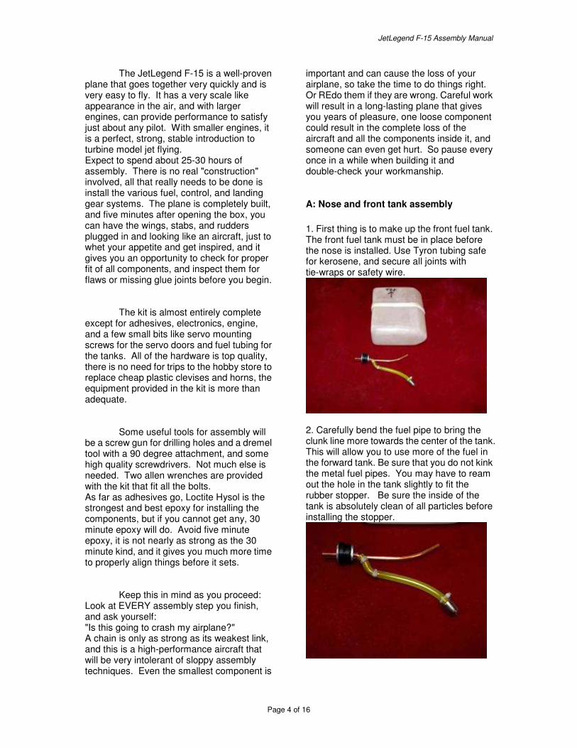
A: Nose and front tank assembly 1. First thing is to make up the front fuel tank. The front fuel tank must be in place before the nose is installed. Use Tyron tubing safe for kerosene, and secure all joints with tie-wraps or safety wire.
2. Carefully bend the fuel pipe to bring the clunk line more towards the center of the tank. This will allow you to use more of the fuel in the forward tank. Be sure that you do not kink the metal fuel pipes. You may have to ream out the hole in the tank slightly to fit the rubber stopper. Be sure the inside of the tank is absolutely clean of all particles before installing the stopper.
JetLegend F-15 Assembly Manual
Page 5 of 16
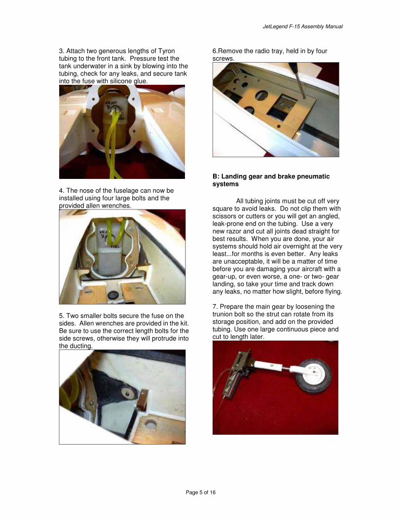
3. Attach two generous lengths of Tyron tubing to the front tank. Pressure test the tank underwater in a sink by blowing into the tubing, check for any leaks, and secure tank into the fuse with silicone glue.
4. The nose of the fuselage can now be installed using four large bolts and the provided allen wrenches.
5. Two smaller bolts secure the fuse on the sides. Allen wrenches are provided in the kit. Be sure to use the correct length bolts for the side screws, otherwise they will protrude into the ducting.
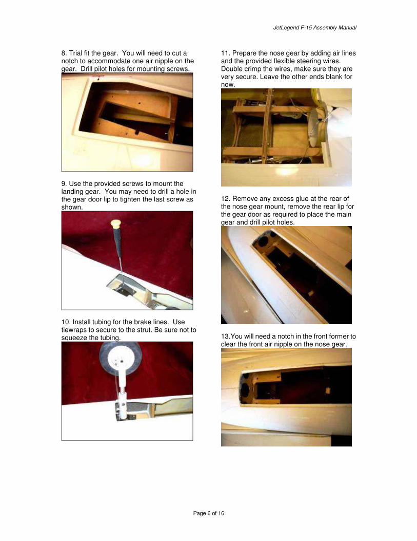
6.Remove the radio tray, held in by four screws.
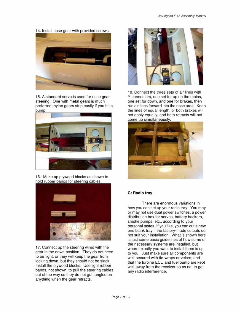
B: Landing gear and brake pneumatic systems All tubing joints must be cut off very square to avoid leaks. Do not clip them with scissors or cutters or you will get an angled, leak-prone end on the tubing. Use a very new razor and cut all joints dead straight for best results. When you are done, your air systems should hold air overnight at the very least...for months is even better. Any leaks are unacceptable, it will be a matter of time before you are damaging your aircraft with a gear-up, or even worse, a one- or two- gear landing, so take your time and track down any leaks, no matter how slight, before flying. 7. Prepare the main gear by loosening the trunion bolt so the strut can rotate from its storage position, and add on the provided tubing. Use one large continuous piece and cut to length later.
JetLegend F-15 Assembly Manual
Page 6 of 16
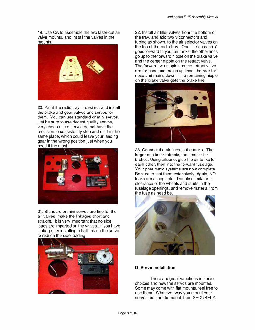
8. Trial fit the gear. You will need to cut a notch to accommodate one air nipple on the gear. Drill pilot holes for mounting screws.
9. Use the provided screws to mount the landing gear. You may need to drill a hole in the gear door lip to tighten the last screw as shown.
10. Install tubing for the brake lines. Use tiewraps to secure to the strut. Be sure not to squeeze the tubing.
11. Prepare the nose gear by adding air lines and the provided flexible steering wires. Double crimp the wires, make sure they are very secure. Leave the other ends blank for now.
12. Remove any excess glue at the rear of the nose gear mount, remove the rear lip for the gear door as required to place the main gear and drill pilot holes.
13.You will need a notch in the front former to clear the front air nipple on the nose gear.
JetLegend F-15 Assembly Manual
Page 7 of 16
14. Install nose gear with provided screws.
15. A standard servo is used for nose gear steering. One with metal gears is much preferred; nylon gears strip easily if you hit a bump.
16. Make up plywood blocks as shown to hold rubber bands for steering cables.
17. Connect up the steering wires with the gear in the down position. They do not need to be tight, or they will keep the gear from locking down, but they should not be slack. Install the plywood blocks. Use light rubber bands, not shown, to pull the steering cables out of the way so they do not get tangled on anything when the gear retracts.
18. Connect the three sets of air lines with Y-connectors, one set for up on the mains, one set for down, and one for brakes, then run air lines forward into the nose area. Keep the lines of equal length, or both brakes will not apply equally, and both retracts will not come up simultaneously.
C: Radio tray There are enormous variations in how you can set up your radio tray. You may or may not use dual power switches, a power distribution box for servos, battery backers, smoke pumps, etc., according to your personal tastes. If you like, you can cut a new one blank tray if the factory-made cutouts do not suit your installation. What is shown here is just some basic guidelines of how some of the necessary systems are installed, but where exactly you want to install them is up to you. Just make sure all components are well-secured with tie-wraps or velcro, and that the turbine ECU and fuel pump are kept well away from the receiver so as not to get any radio interference.
JetLegend F-15 Assembly Manual
Page 8 of 16
19. Use CA to assemble the two laser-cut air valve mounts, and install the valves in the mounts.
20. Paint the radio tray, if desired, and install the brake and gear valves and servos for them. You can use standard or mini servos, just be sure to use decent quality servos, very cheap micro servos do not have the precision to consistently stop and start in the same place, which could leave your landing gear in the wrong position just when you need it the most.
21. Standard or mini servos are fine for the air valves, make the linkages short and straight. It is very important that no side loads are imparted on the valves...if you have leakage, try installing a ball link on the servo to reduce the side loading.
22. Install air filler valves from the bottom of the tray, and add two y-connectors and tubing as shown, to the air selector valves on the top of the radio tray. One line on each Y goes forward to your air tanks, the other lines go up to the forward nipple on the brake valve and the center nipple on the retract valve. The forward two nipples on the retract valve are for nose and mains up lines, the rear for nose and mains down. The remaining nipple on the brake valve gets the brake line.
23. Connect the air lines to the tanks. The larger one is for retracts, the smaller for brakes. Using silicone, glue the air tanks to each other, then into the forward fuselage. Your pneumatic systems are now complete. Be sure to test them extensively. Again, NO leaks are acceptable. Double check for all clearance of the wheels and struts in the fuselage openings, and remove material from the fuse as need be.
D: Servo installation There are great variations in servo choices and how the servos are mounted. Some may come with flat mounts, feel free to use them. Whatever way you mount your servos, be sure to mount them SECURELY.
JetLegend F-15 Assembly Manual
Page 9 of 16
Any play may result in flutter and the loss of your aircraft. The aluminum mounts and plywood blocks provided in the kit can be modified accordingly to suit the servos you chose. Do not use rubber servo grommets, they are to dampen the vibration of a glow engine, turbine engines produce no vibration, so all the grommets will do is allow the servo to move and lead to potential flutter. Digital servos are highly recommended on all flight controls, as are servos with metal gears. Plastic gears can chip a tooth if the control surface is bumped while assembling the aircraft at the field, and it's too easy for this situation to go unnoticed until the servo fails in the air. Metal servo arms are also good insurance against flutter. The linkages and fiberglass control horns provided in the kit are extremely strong, there is no need to replace them with aftermarket ones. Be sure to use all the provided retention hardware, including the tiny circlips. They are all there for a reason. The horns on your servos and the holes in the fiberglass control horns provided in the kit may need to be drilled out to accommodate the clevis pins. It's easier to do this to all of the horns before any assembly. Do this carefully, and discard anything with an oversized hole, as any slop here is unacceptable. It is highly recommended that all servos be "burned in" for an hour or so before installation, using a servo driver to exercise the servo. Most failures of brand-new electronics will occur during the first hour of operation. Better to find out now than later. The control surface hinges come from the factory unglued. It is absolutely essential that you remove and glue each and every one into place. Coat the center of each hinge with petroleum jelly to keep it from getting bound up with glue. Apply plenty of epoxy to one side of the hinge, and plenty of epoxy into the matching hole in the surface, install the hinge, then move the free part of the hinge perpendicular to the surface for proper alignment while drying. Do only one side of the hinging at a time, do not attempt to glue the hinges into both surfaces simultaneously. If you are painting your model, you may wish to leave the hinges unglued so the surfaces can be removed for painting. Just don't forget to glue them AFTER painting!
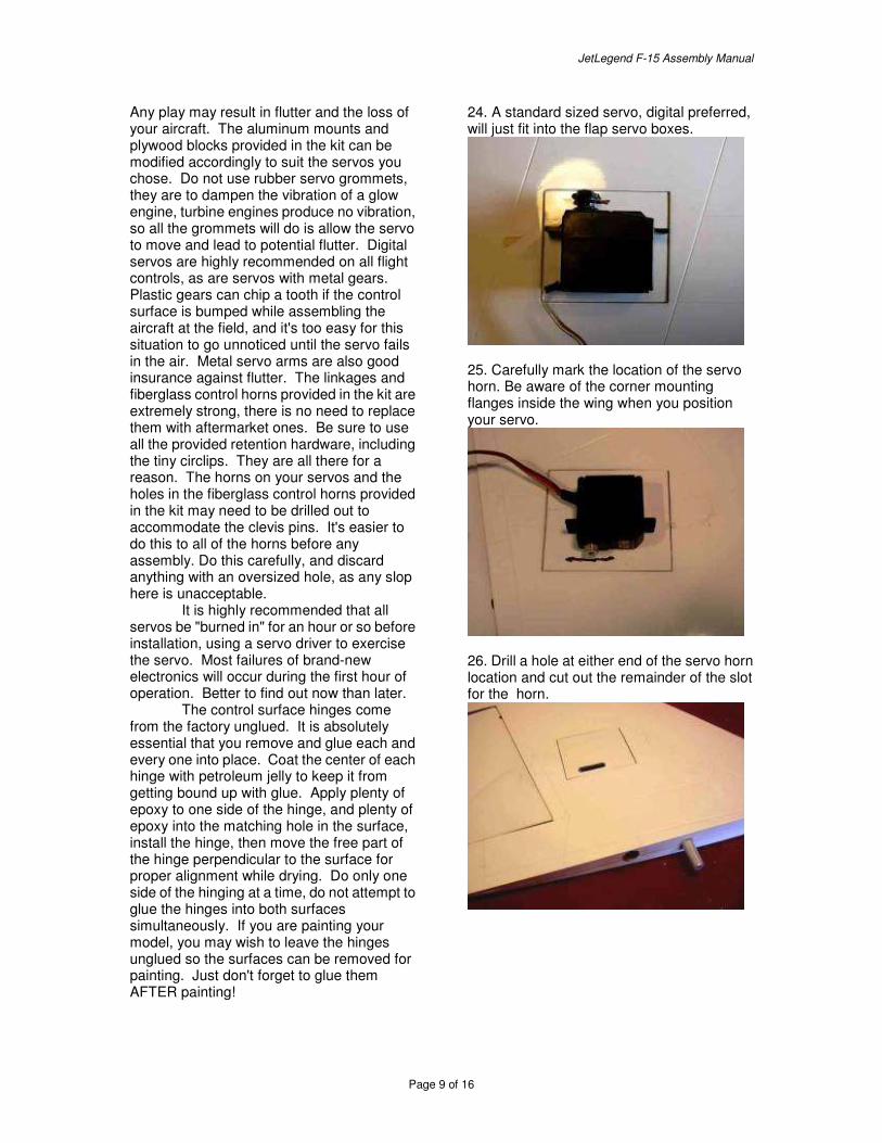
24. A standard sized servo, digital preferred, will just fit into the flap servo boxes.
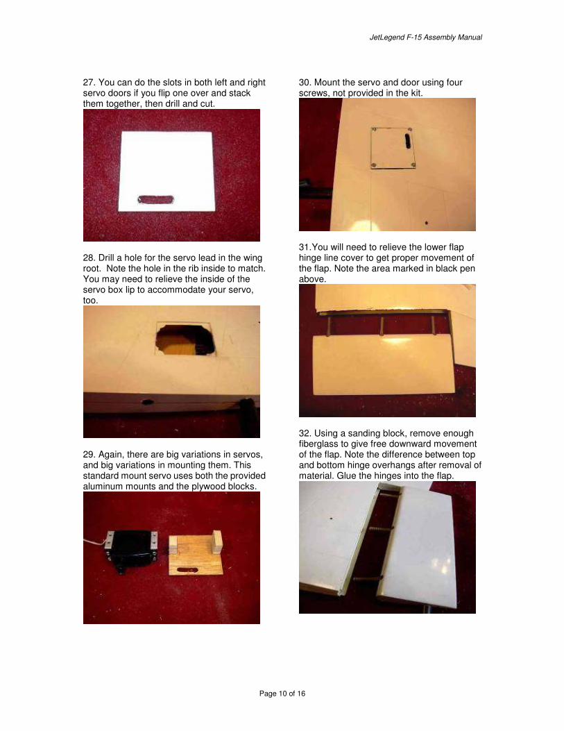
25. Carefully mark the location of the servo horn. Be aware of the corner mounting flanges inside the wing when you position your servo.
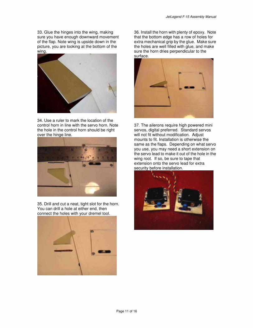
26. Drill a hole at either end of the servo horn location and cut out the remainder of the slot for the horn.
JetLegend F-15 Assembly Manual
Page 10 of 16
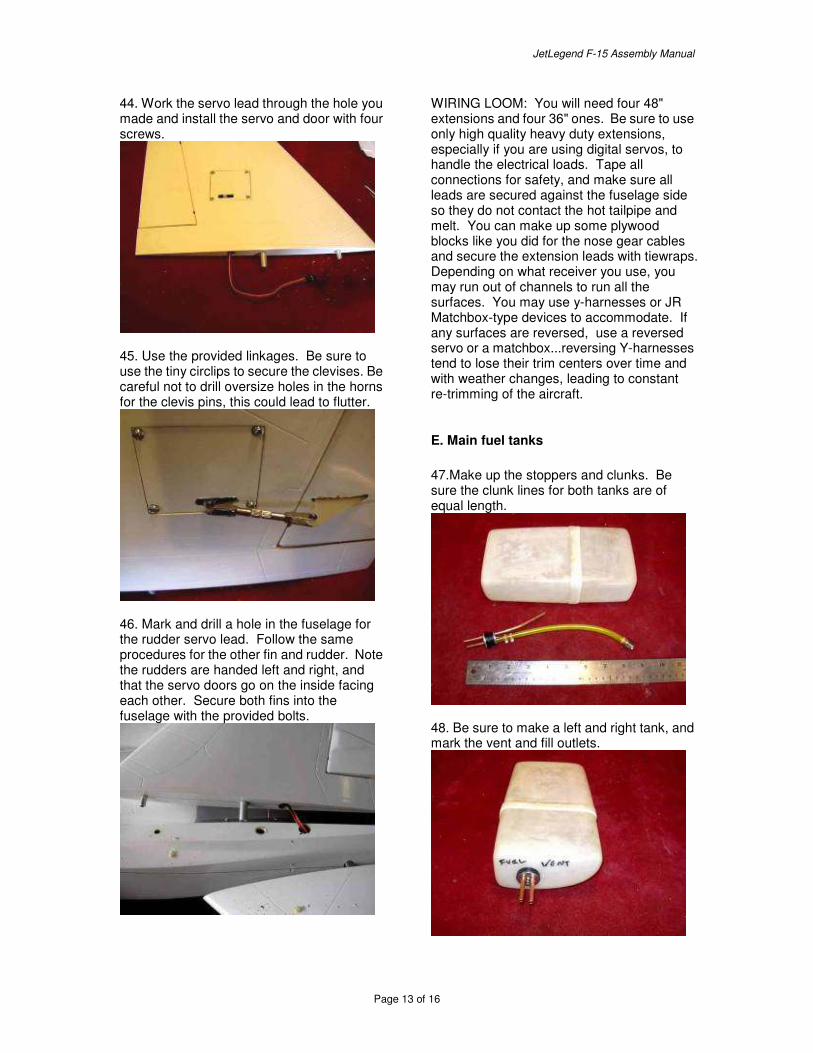
27. You can do the slots in both left and right servo doors if you flip one over and stack them together, then drill and cut.
28. Drill a hole for the servo lead in the wing root. Note the hole in the rib inside to match. You may need to relieve the inside of the servo box lip to accommodate your servo, too.
29. Again, there are big variations in servos, and big variations in mounting them. This standard mount servo uses both the provided aluminum mounts and the plywood blocks.
30. Mount the servo and door using four screws, not provided in the kit.
31.You will need to relieve the lower flap hinge line cover to get proper movement of the flap. Note the area marked in black pen above.
32. Using a sanding block, remove enough fiberglass to give free downward movement of the flap. Note the difference between top and bottom hinge overhangs after removal of material. Glue the hinges into the flap.
JetLegend F-15 Assembly Manual
Page 11 of 16
33. Glue the hinges into the wing, making sure you have enough downward movement of the flap. Note wing is upside down in the picture, you are looking at the bottom of the wing.
34. Use a ruler to mark the location of the control horn in line with the servo horn. Note the hole in the control horn should be right over the hinge line.
35. Drill and cut a neat, tight slot for the horn. You can drill a hole at either end, then connect the holes with your dremel tool.
36. Install the horn with plenty of epoxy. Note that the bottom edge has a row of holes for extra mechanical grip by the glue. Make sure the holes are well filled with glue, and make sure the horn dries perpendicular to the surface.
37. The ailerons require high powered mini servos, digital preferred. Standard servos will not fit without modification. Adjust mounts to fit. Installation is otherwise the same as the flaps. Depending on what servo you use, you may need a short extension on the servo lead to make it out of the hole in the wing root. If so, be sure to tape that extension onto the servo lead for extra security before installation.

JetLegend F-15 Assembly Manual
Page 12 of 16
38. Completed wing with aileron and flap linkages. Be sure to use all clevis retention hardware. Again, also be sure to not make the clevis holes in any horns oversize, any slop may cause flutter.
39. The elevator servos can be standard size or larger. Digital preferred. Prepare two servos with their mounts, and be sure to drill out the horns for the provided hardware before installation.
40. The elevator servos are installed as shown. Drill holes to access the screws through the outer fuselage or reverse the mounts accordingly.
41. Install the stabs and tighten the securely with the provided allen wrench. Be sure there is adequate spacing so the stabs do not touch the fuse.
42. Locate your rudder servo onto the servo door. Note a smaller than standard servo is needed. Digital servos are preferred, but not required. A flat mount servo is very convenient for this application.
43. Drill a hole for the servo lead on the bottom of the rudder. Note there is a hole in the internal balsa rib, line the hole up with the hole in the rib.
JetLegend F-15 Assembly Manual
Page 13 of 16
44. Work the servo lead through the hole you made and install the servo and door with four screws.
45. Use the provided linkages. Be sure to use the tiny circlips to secure the clevises. Be careful not to drill oversize holes in the horns for the clevis pins, this could lead to flutter.
46. Mark and drill a hole in the fuselage for the rudder servo lead. Follow the same procedures for the other fin and rudder. Note the rudders are handed left and right, and that the servo doors go on the inside facing each other. Secure both fins into the fuselage with the provided bolts.
WIRING LOOM: You will need four 48" extensions and four 36" ones. Be sure to use only high quality heavy duty extensions, especially if you are using digital servos, to handle the electrical loads. Tape all connections for safety, and make sure all leads are secured against the fuselage side so they do not contact the hot tailpipe and melt. You can make up some plywood blocks like you did for the nose gear cables and secure the extension leads with tiewraps. Depending on what receiver you use, you may run out of channels to run all the surfaces. You may use y-harnesses or JR Matchbox-type devices to accommodate. If any surfaces are reversed, use a reversed servo or a matchbox...reversing Y-harnesses tend to lose their trim centers over time and with weather changes, leading to constant re-trimming of the aircraft.
E. Main fuel tanks 47.Make up the stoppers and clunks. Be sure the clunk lines for both tanks are of equal length.
48. Be sure to make a left and right tank, and mark the vent and fill outlets.

JetLegend F-15 Assembly Manual
Page 14 of 16
49. Add vent and fill lines to tanks. Note that the lines for both tanks must be identical in length for proper even fuel draw. Pressure tests the tanks in a sink, fix any leaks, no matter how small.
50. Install the tanks using silicone glue. Be sure to keep the glue only in places where you can get to it, in case you need to cut through the glue to remove the tanks for servicing.
51. Add a t-fitting and a section of tubing to the main tank fill lines and run the line to the vent of the forward tank.
52. Add a t-fitting to the vent lines of the main tanks and run a line to atmosphere or to a festo fitting for a taxi tank. A taxi tank is simply an external fuel tank that can sit on the
wing and feed fuel into the main tanks while taxiing and waiting to take off, so you can remove it right before takeoff and always take off with a full fuel load.
F. Tailpipe and bypass 53. Loosen the rear bridge piece, raise it, and test fit the tailpipe.
54. Install six plywood standoff blocks for the tailpipe.
JetLegend F-15 Assembly Manual
Page 15 of 16
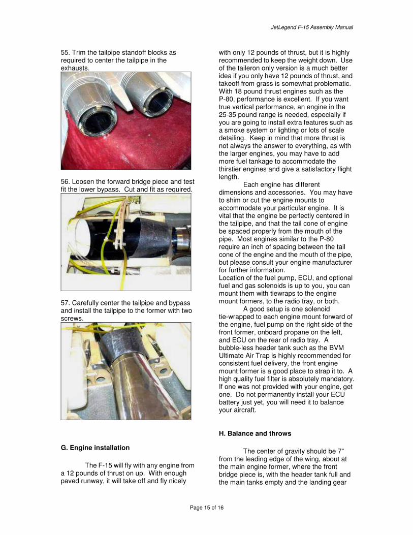
55. Trim the tailpipe standoff blocks as required to center the tailpipe in the exhausts.
56. Loosen the forward bridge piece and test fit the lower bypass. Cut and fit as required.
57. Carefully center the tailpipe and bypass and install the tailpipe to the former with two screws.
G. Engine installation The F-15 will fly with any engine from a 12 pounds of thrust on up. With enough paved runway, it will take off and fly nicely
with only 12 pounds of thrust, but it is highly recommended to keep the weight down. Use of the taileron only version is a much better idea if you only have 12 pounds of thrust, and takeoff from grass is somewhat problematic. With 18 pound thrust engines such as the P-80, performance is excellent. If you want true vertical performance, an engine in the 25-35 pound range is needed, especially if you are going to install extra features such as a smoke system or lighting or lots of scale detailing. Keep in mind that more thrust is not always the answer to everything, as with the larger engines, you may have to add more fuel tankage to accommodate the thirstier engines and give a satisfactory flight length. Each engine has different dimensions and accessories. You may have to shim or cut the engine mounts to accommodate your particular engine. It is vital that the engine be perfectly centered in the tailpipe, and that the tail cone of engine be spaced properly from the mouth of the pipe. Most engines similar to the P-80 require an inch of spacing between the tail cone of the engine and the mouth of the pipe, but please consult your engine manufacturer for further information. Location of the fuel pump, ECU, and optional fuel and gas solenoids is up to you, you can mount them with tiewraps to the engine mount formers, to the radio tray, or both. A good setup is one solenoid tie-wrapped to each engine mount forward of the engine, fuel pump on the right side of the front former, onboard propane on the left, and ECU on the rear of radio tray. A bubble-less header tank such as the BVM Ultimate Air Trap is highly recommended for consistent fuel delivery, the front engine mount former is a good place to strap it to. A high quality fuel filter is absolutely mandatory. If one was not provided with your engine, get one. Do not permanently install your ECU battery just yet, you will need it to balance your aircraft.
H. Balance and throws The center of gravity should be 7" from the leading edge of the wing, about at the main engine former, where the front bridge piece is, with the header tank full and the main tanks empty and the landing gear
JetLegend F-15 Assembly Manual
Page 16 of 16
retracted. Move your radio and ECU batteries around to get the proper CG, then secure them WELL wherever they need to be, most probably all the way in the nose. Velcro straps are a great way of securing the batteries. The elevator throws should be 1.75 inches up and down for high rates, the ailerons 1 inch up and down at high rates, the flaps 1 inch of down, the rudders 3/4" left and right. There is plenty of tolerance in both the C/G and throws, the plane will not become twitchy or radically unstable if you are off a little bit, there is a lot of room to adjust things to your own personal taste.
I. Range check and final preparations A high quality PCM receiver is recommended, and failsafe should be set to shut the engine off in the event of loss of radio signal. If the engine is shut down for even a second or two before a crash, it GREATLY reduces the chances of a fire. It is also recommended that failsafe for the flight controls be set to induce a snap roll and spin into the ground in the event of loss of signal...from a safety standpoint, it's better for the aircraft to crash immediately, and hopefully over the flying field, than have the controls lock in a neutral position and have the uncontrolled aircraft travel some distance. A whip antenna is available from JetLegend and is highly recommended, as an internal antenna can be blocked by the internal carbon fiber and metal components of the airframe. Be sure to THOROUGHLY range check the aircraft with the engine running. Be sure to range-check the model with the turbine both running and the turbine shut down. If there is any DIFFERENCE between the two, find out what component of the turbine system, the fuel pump or the ECU, is interfering with the receiver reception, and relocate the components until there is no loss of signal strength with the engine running. This is vital.