Embed Size (px)
Citation preview

Liam Worth JET EiC Training & Refresher Course 1st May 2007
JET Vessel Conditioning Systems
EiC Training and Refresher Course
1st May 2007
Liam Worth JET EiC Training & Refresher Course 1st May 2007
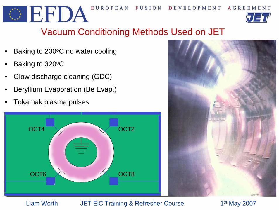
Vacuum Conditioning Methods Used on JET
• Baking to 200oC no water cooling
• Baking to 320oC
• Glow discharge cleaning (GDC)
• Beryllium Evaporation (Be Evap.)
• Tokamak plasma pulses
Liam Worth JET EiC Training & Refresher Course 1st May 2007
The Gas and Electrical Baking system
WHY BAKE ?Wall Conditioning (and recycling):-
• Increase the outgassing rate of impurities. • Increase the effectiveness of GDC.• Helps prevent GDC arcing and sputtering.• Increased pumping from Be getter.• Faster recovery from discharges.• Improved density control and pulse termination.
Other reasons:-
• Expansion of vessel moves it free of MVP packing blocks. (~1mm /50 C)• Stops divertor cryo-pump freezing baffle water circuits.• Desorption of Tritium for clean up.
Liam Worth JET EiC Training & Refresher Course 1st May 2007
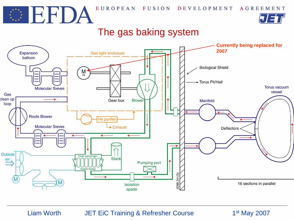
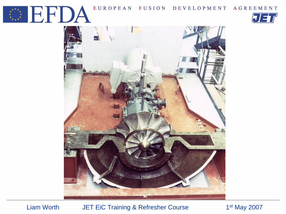
The gas baking systemCurrently being replaced for 2007
Liam Worth JET EiC Training & Refresher Course 1st May 2007
Liam Worth JET EiC Training & Refresher Course 1st May 2007
Liam Worth JET EiC Training & Refresher Course 1st May 2007
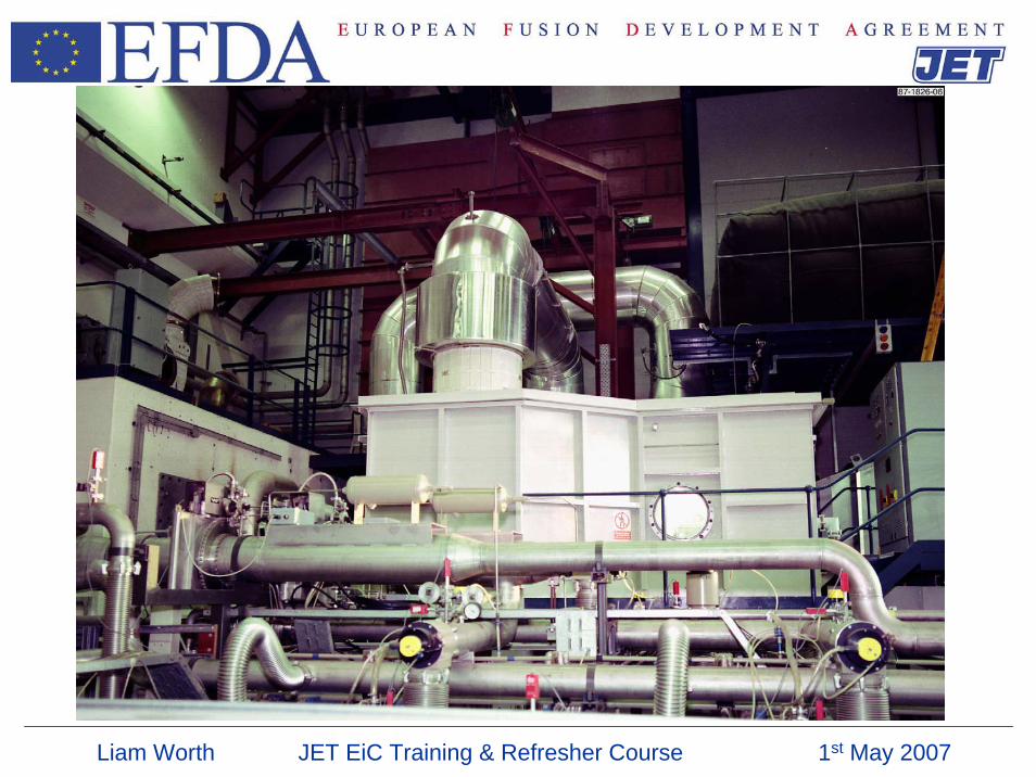
Gas Baking system- Motor replacement
• The old motor will not run at high speed (motor winding problem)and JET baking is limited to 220°C
• The old motor is started direct online and high electrical loads at start up have caused problems for other JET systems (i.e. DRS)
• Motor to be replaced with a variable speed motor – will restore JET’sbaking capability
Liam Worth JET EiC Training & Refresher Course 1st May 2007
The Gas Baking control system
• Main PLC controls plant operation and including interlocks, instrumentation.
• User interface and the selection the of the heating and cooling element is performed by a second PLC.
• Torus Temperature measurement and generation of interlocks to DPIS and CISS is performed by dual high integrity PLC system.
• Temperature control is performed by a dedicated controller. The Process variable of the Master loop is vessel temperature. The process variable of the slave loop is the feed temperature of the gas loop.
• Six standard baking operations can be selected by push buttons on a local control panel.
• Target temperature can be selected from CODAS in 10o steps between 20o C and 320o
C.
• Gas baking acts as master over electrical baking.
Liam Worth JET EiC Training & Refresher Course 1st May 2007
Performance of the plant Blower• Air:- Speed 2400 rpm. Flow 11 m3/s,
• Power into gas loop 190kW (at 20oC)
• He :- Speed 4830 rpm. Flow 22 m3/s
• Power into gas loop 280kW ( at 20oC)
Heater banks• 2 banks thyristor controlled, power 130kW
• 12 banks on/off controlled, power 650kW
Cooling power (at 150oC)• Heat exchanger doors 150kW
• Fan F between 150kW and 600kW
• Fan K below 600kW
Liam Worth JET EiC Training & Refresher Course 1st May 2007
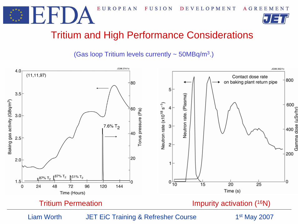
Tritium and High Performance Considerations
(Gas loop Tritium levels currently ~ 50MBq/m3.)
Tritium Permeation Impurity activation (16N)
Liam Worth JET EiC Training & Refresher Course 1st May 2007
Significant temperatures
GENERAL
3200 C Maximum guaranteed achievable nominal temperature.Maximum nominal safe temperature for divertor coils.
250o C Maximum temperature for filling duct scrapers.
200o C Maximum baking temperature without water.
1800 C Low to high speed switch over. (no longer applies with variable speed drive)
100o C Minimum temperature to give required operational clearance from MVP packing. Maximum temperature for filling of baffle and target plates.
DPIS
Vessel > 100oC (and low water flow) risk of baffles boiling initiate timed purge.
Vessel < 120oC Cryo freeze up risk cryo inhibited.
Vessel > 350oC Thermal stress, inhibit cryo.
Liam Worth JET EiC Training & Refresher Course 1st May 2007
Why 4He as the process gas ?
• Good thermodynamic properties.
• No activation.
• Ease of cleaning in case of tritium permeation.
• Low-z hence tolerance of system to higher leak rate from interspace to vessel
May run on air until next tritium campaign. This allows lower blower speed, even at 320°C, reducing stress on blower.
Liam Worth JET EiC Training & Refresher Course 1st May 2007
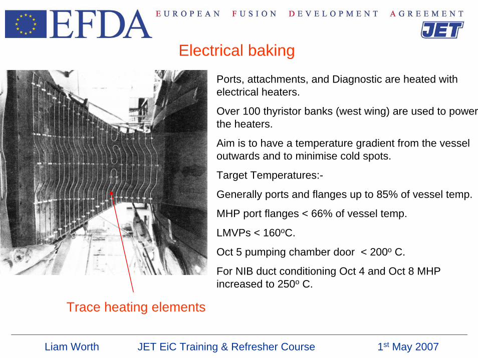
Electrical baking
Ports, attachments, and Diagnostic are heated with electrical heaters.
Over 100 thyristor banks (west wing) are used to power the heaters.
Aim is to have a temperature gradient from the vessel outwards and to minimise cold spots.
Target Temperatures:-
Generally ports and flanges up to 85% of vessel temp.
MHP port flanges < 66% of vessel temp.
LMVPs < 160oC.
Oct 5 pumping chamber door < 200o C.
For NIB duct conditioning Oct 4 and Oct 8 MHP increased to 250o C.
Trace heating elements
Liam Worth JET EiC Training & Refresher Course 1st May 2007
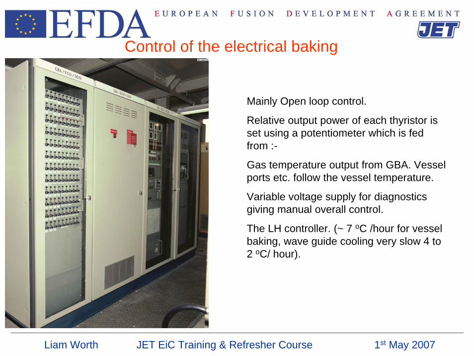
Control of the electrical baking
Mainly Open loop control.
Relative output power of each thyristor is set using a potentiometer which is fed from :-
Gas temperature output from GBA. Vessel ports etc. follow the vessel temperature.
Variable voltage supply for diagnostics giving manual overall control.
The LH controller. (~ 7 oC /hour for vessel baking, wave guide cooling very slow 4 to 2 oC/ hour).
Liam Worth JET EiC Training & Refresher Course 1st May 2007
Heating and Cooling
Heating 20oC to 250oC ~10oC /hour
Heating 280oC to 320oC ~5oC /hour
Normal Cool down 320oC to 20oC ~10oC/hour
Fast Cool down 320oC to 250oC ~20oC /hour
Emergency Procedures
Unplanned deviation in Torus average temperature
Rapid:- Stop pulsing, unlock supports, turn off baking plant, call on-call RO.Slow:- (or step) call on-call RO.
Over or under temperature on vessel port
< 200 C unexplained port temperature change in 24 hours.
If on main port:- possible unlocking and cooling of vessel to 100o C.
J1S UPS power failure
Connect and start Propane generator for emergency oil cooling.
Liam Worth JET EiC Training & Refresher Course 1st May 2007
Rotary valve baking
• Baking only required only after a valve replaced.
• Valve must be open when baked.
• Valve can not be moved when above 60°C.
• When sealed has to be open if the ΔT between the rotor and the body exceeds 30°C.
Liam Worth JET EiC Training & Refresher Course 1st May 2007
Possible reasons for un-planned cooling of the vessel
•Large air leak
•Vessel water leak
•Failure of TF cooling (10 hours)
•Failure of divertor coils Galden cooling
•Failure of shielding beams and doors
Liam Worth JET EiC Training & Refresher Course 1st May 2007
Useful information
• When conditioning the vessel after a vent, monitor the evolution of H2O (use RGA)
When trend is significantly down consider cooling the PD nitrogen, but not before as water will be stored on panel for release at a later date de-conditioning the vessel
• MOGDOC 9.06 Gas Bakeout System - Operation
• MOGDOC 3.35 Gas Bakeout Plant Failures• MOGDOC 3.14 Unplanned Deviation in Torus Average Temperature
Liam Worth JET EiC Training & Refresher Course 1st May 2007
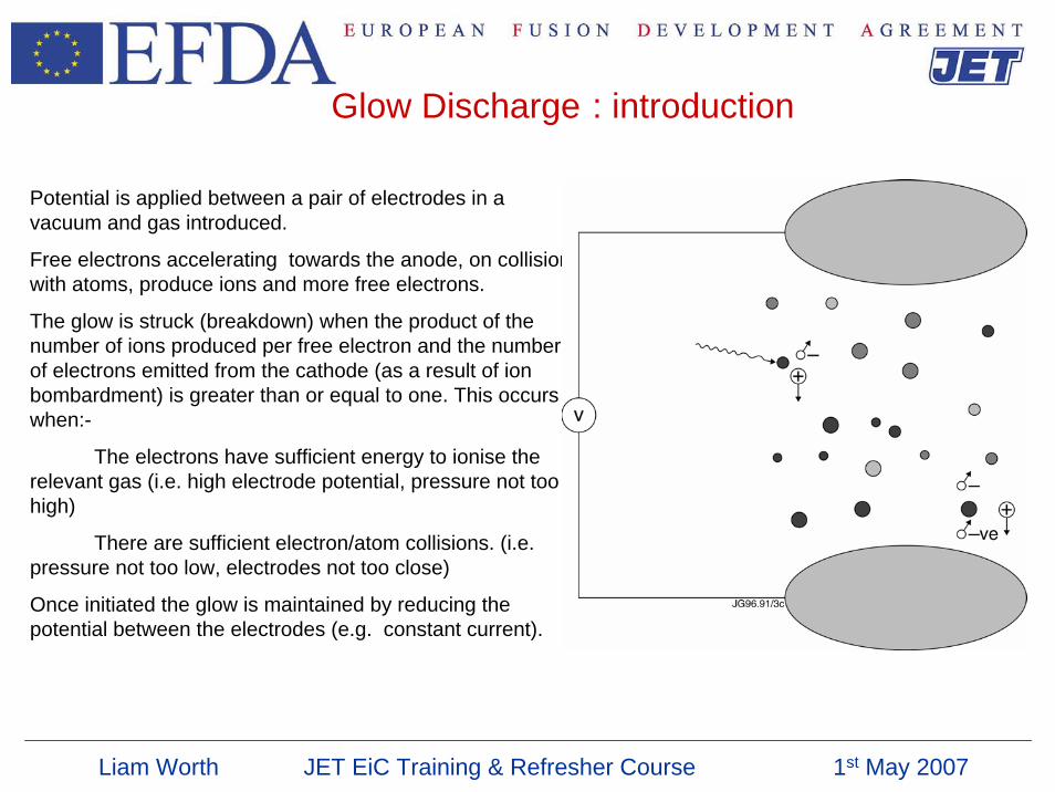
Glow Discharge : introduction
Potential is applied between a pair of electrodes in a vacuum and gas introduced.
Free electrons accelerating towards the anode, on collision with atoms, produce ions and more free electrons.
The glow is struck (breakdown) when the product of the number of ions produced per free electron and the number of electrons emitted from the cathode (as a result of ion bombardment) is greater than or equal to one. This occurs when:-
The electrons have sufficient energy to ionise the relevant gas (i.e. high electrode potential, pressure not too high)
There are sufficient electron/atom collisions. (i.e. pressure not too low, electrodes not too close)
Once initiated the glow is maintained by reducing the potential between the electrodes (e.g. constant current).
Liam Worth JET EiC Training & Refresher Course 1st May 2007
Uses of Glow Discharge Cleaning (GDC) on JET
•Recovery of vacuum conditions following intervention or leaks.
•Maintaining First Wall condition.
•Helium glow to reduce uncontrolled gas recycling contributions to plasma fuelling.
•Tritium clean up.
•Static glow in Tritium can be used for wall doping.
•High voltage GDC in D2 can be used to improve the 4He background prior to leak testing.
Liam Worth JET EiC Training & Refresher Course 1st May 2007
The GDC Cleaning ProcessHydrogen (H2 and D2) GDC is primarily reactive
Impurities released include Water, Carbon Monoxide, Hydrocarbons (e.g. Methane).
e.g. Hydrogen reacts with oxides on the surface leading to the release of water.
He GDC work by mainly ion induced desorption
Impurities released include Water, Carbon Monoxide, Carbon Dioxide, Hydrogen.
The cleaning rate is dependant on:-
The impurity levels on the wall. (how dirty!)
The pumping speed. *
The ion flux at the wall. * (and area covered)
The ion energy at the wall. *
The glow gas.
The vessel temperature. (* Effected by glow pressure.)
Liam Worth JET EiC Training & Refresher Course 1st May 2007
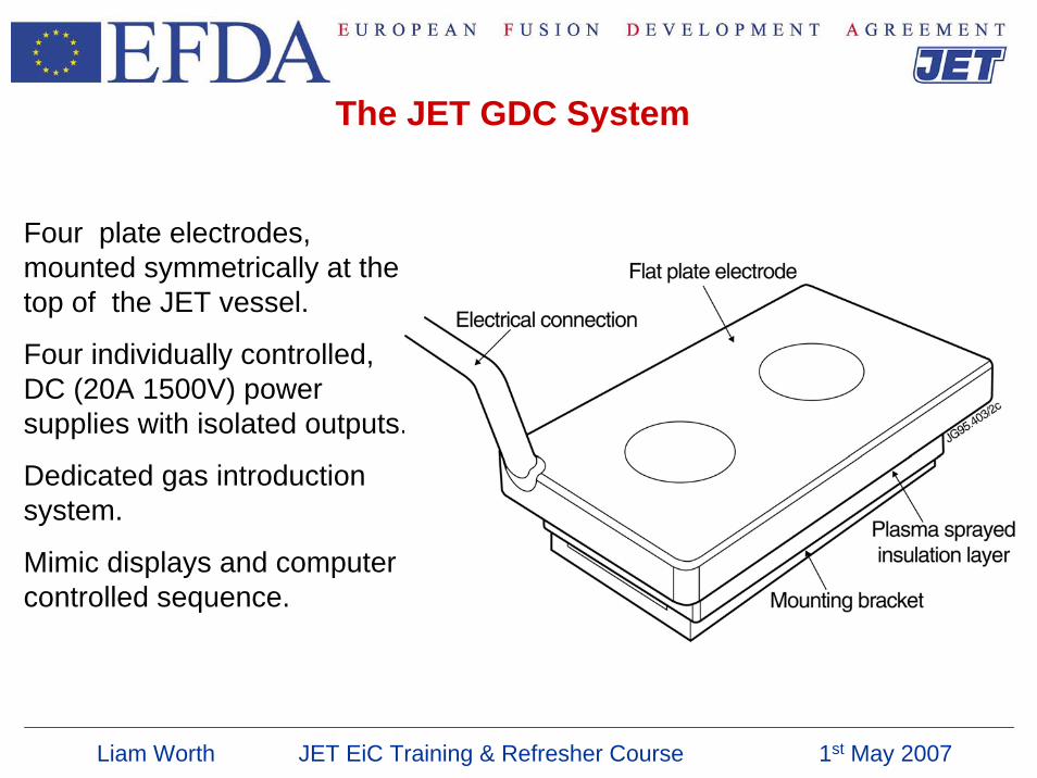
The JET GDC System
Four plate electrodes, mounted symmetrically at the top of the JET vessel.
Four individually controlled, DC (20A 1500V) power supplies with isolated outputs.
Dedicated gas introduction system.
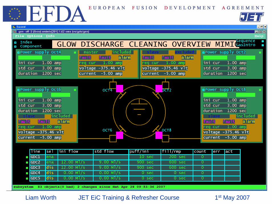
Mimic displays and computer controlled sequence.
Liam Worth JET EiC Training & Refresher Course 1st May 2007
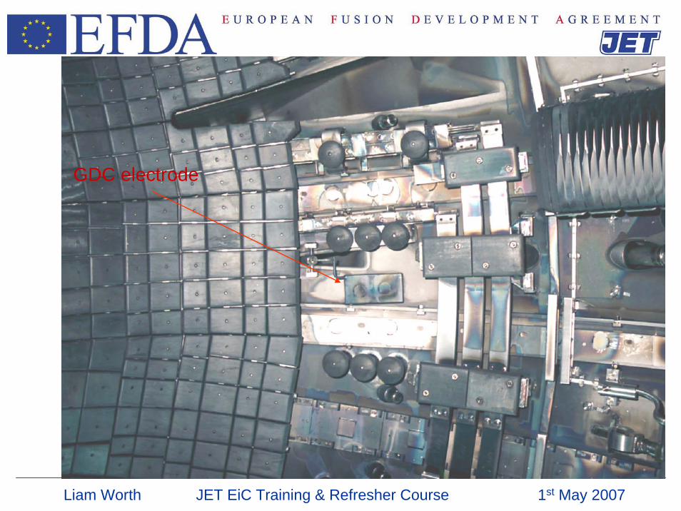
GDC electrode
Liam Worth JET EiC Training & Refresher Course 1st May 2007
Liam Worth JET EiC Training & Refresher Course 1st May 2007
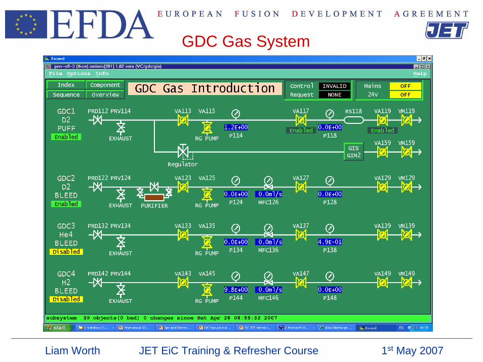
GDC Gas System
Liam Worth JET EiC Training & Refresher Course 1st May 2007
• GDC is run using a CODAS( level 2) control sequence usually by Shift techs.• The glow sequence does the required vessel isolations. • The following checks are made prior to initiating the glow:-
Pulse off.Rotary valves closed. (Vt 1 and Vt 2) Diagnostic valves closed.Flap valve closed.( lhcd V3*)Earth switches closed.Argon frosting disabled. Divertor cryo He loop warm.Rotary valve turbo pumps pumping.IVIS ValvesJ25 He inhibit and J25 D2 inhibit.
• Parameters for power supplies and gas introduction will need to be set up but once optimised in commissioning will generally not change.
• A glow discharge can be initiated within a few minutes if other systems are in the correct state.
Operation of GDC
Liam Worth JET EiC Training & Refresher Course 1st May 2007
Operation of GDC : LHCD V3
• GDC can be carried out with the LHCD flap valve open only if LHCD LHe cryopanel is warm
• GDC can be carried out with the LHCD flap valve closed with the LHCD LHe cryopanel cold – watch LHCD pressure when doing Helium glow as pressure can rise above DPIS limit (3 x 10 -3 mbar) and inhibit cryogens
Liam Worth JET EiC Training & Refresher Course 1st May 2007
• Glow will normally be ended using the control sequence.
• Mass spectra taken with and without the GDC power supplies on (but with gas on) can be helpful for analysing the effectiveness of the glow.
• Time should be allowed after glow for outgassing of the glow gas.
• As a rule of thumb a partial pressure of < 3X10⁻⁸ mbar for mass 28 should be achieved prior to Be evaporation.
GDC : Ending Glow
Liam Worth JET EiC Training & Refresher Course 1st May 2007
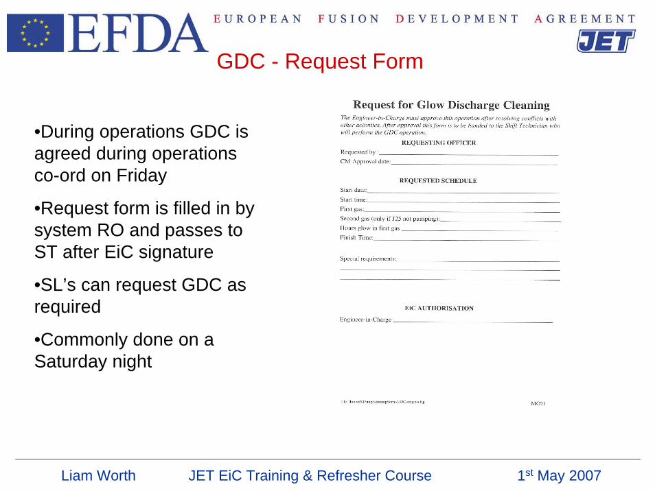
GDC - Request Form
•During operations GDC is agreed during operations co-ord on Friday
•Request form is filled in by system RO and passes to ST after EiC signature
•SL’s can request GDC as required
•Commonly done on a Saturday night
Liam Worth JET EiC Training & Refresher Course 1st May 2007
GDC – Useful information
• Peak at 28, smaller peaks at 30 & 32
• During productive D2 glow 28 peak is dominant over 30 peak.
• As D2 glow becomes less effective peaks at 30 & 32 rise
• D2 GDC will create hydrocarbons, especially round mass 40
• When peaks at 30 & 32 are ~ 50% of peak at 28 may be better to switch to helium glow
MOGDOC 9.04 Glow Discharge Cleaning (GDC)
Liam Worth JET EiC Training & Refresher Course 1st May 2007
GDC – Useful information
• Turn off current to electrodes and leave gas flowing.
• The change in magnitude of Mass 28 on RGA (most contamination removed as CO) indicates how much benefit there is from the glow
• In a dirty system 28 may change by factor 100• After ~100 hours D2 glow 28 peak may only change by factor
10• In clean system 28 peak may only change by a factor 5
Liam Worth JET EiC Training & Refresher Course 1st May 2007
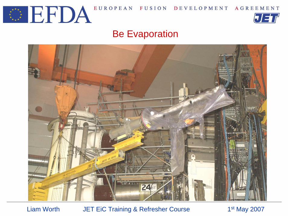
Be Evaporation
Liam Worth JET EiC Training & Refresher Course 1st May 2007
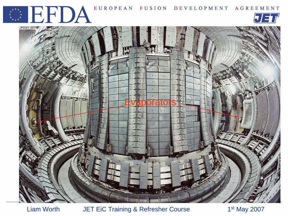
Evaporators
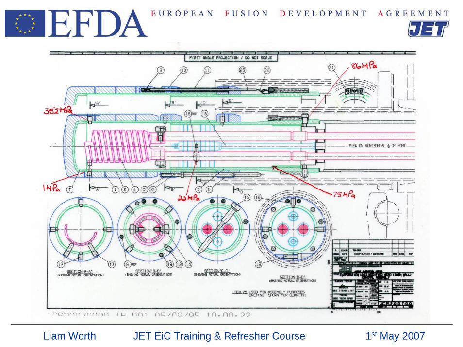
Liam Worth JET EiC Training & Refresher Course 1st May 2007
Liam Worth JET EiC Training & Refresher Course 1st May 2007
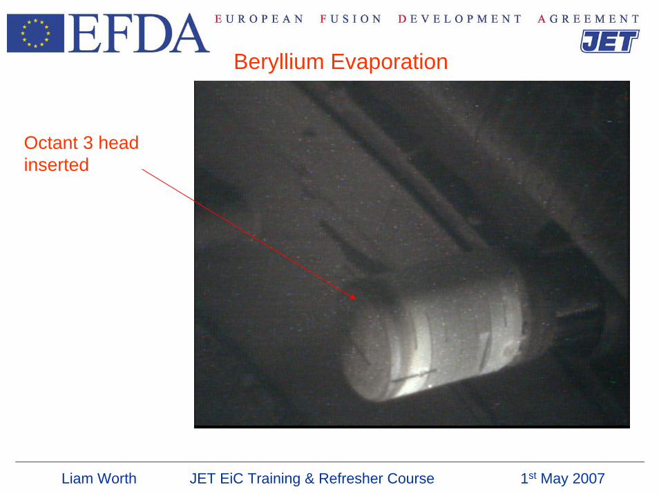
Beryllium Evaporation
Octant 3 head inserted
Liam Worth JET EiC Training & Refresher Course 1st May 2007
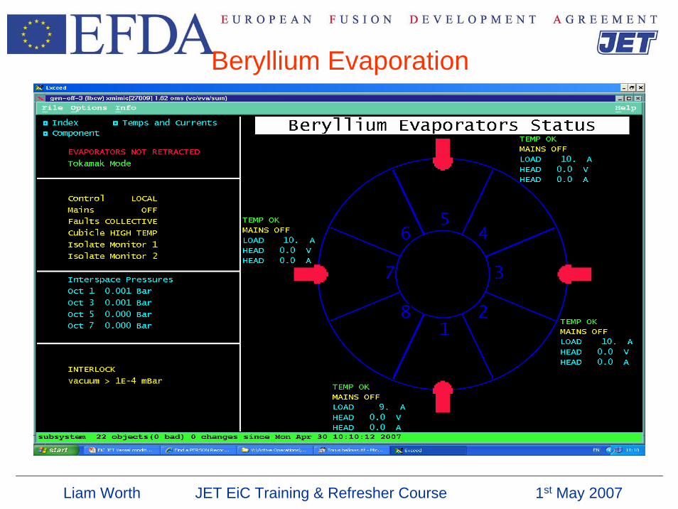
Beryllium Evaporation
Liam Worth JET EiC Training & Refresher Course 1st May 2007
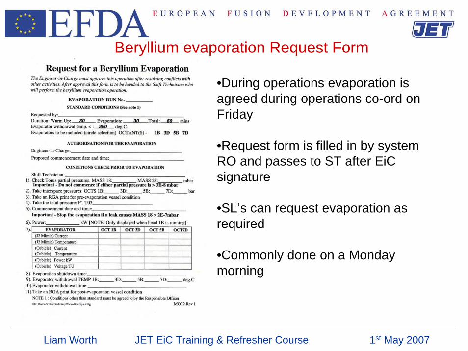
Beryllium evaporation Request Form
•During operations evaporation is agreed during operations co-ord on Friday
•Request form is filled in by system RO and passes to ST after EiC signature
•SL’s can request evaporation as required
•Commonly done on a Monday morning
Liam Worth JET EiC Training & Refresher Course 1st May 2007
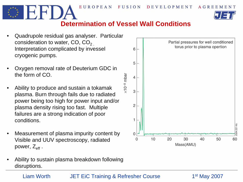
Determination of Vessel Wall Conditions• Quadrupole residual gas analyser. Particular
consideration to water, CO, CO2 . Interpretation complicated by invesselcryogenic pumps.
• Oxygen removal rate of Deuterium GDC in the form of CO.
• Ability to produce and sustain a tokamak plasma. Burn through fails due to radiated power being too high for power input and/or plasma density rising too fast. Multiple failures are a strong indication of poor conditions.
• Measurement of plasma impurity content by Visible and UUV spectroscopy, radiated power, Zeff .
• Ability to sustain plasma breakdown following disruptions.
Liam Worth JET EiC Training & Refresher Course 1st May 2007
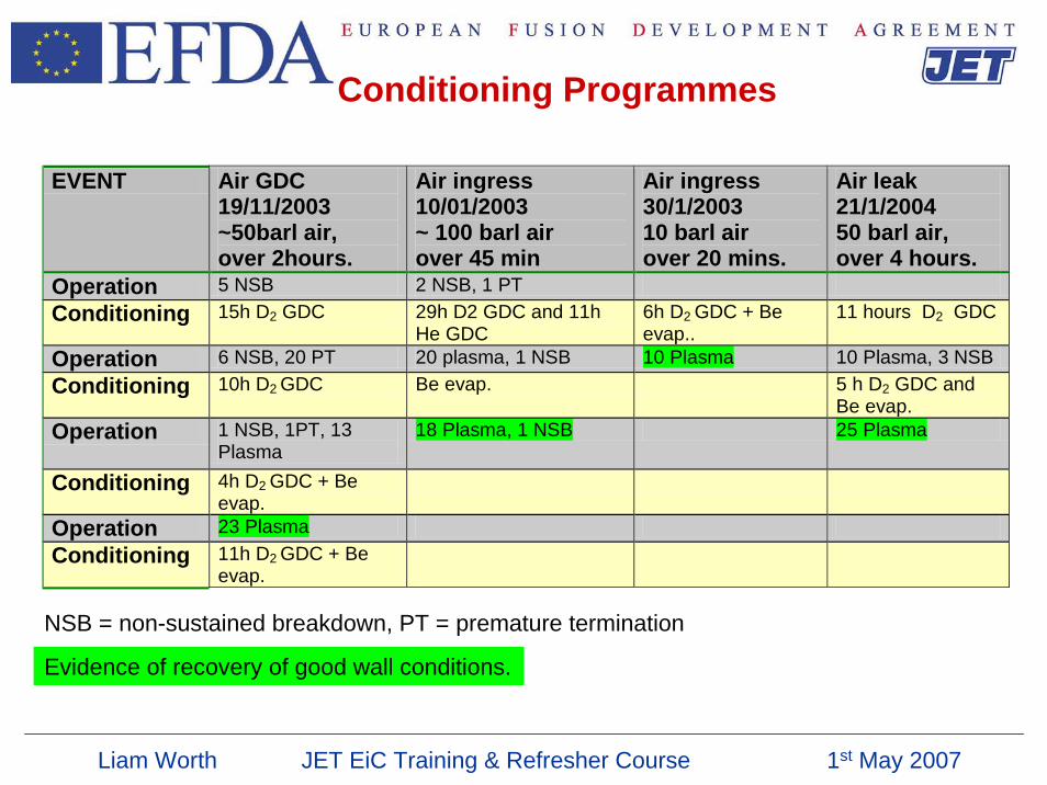
Conditioning Programmes
EVENT Air GDC 19/11/2003 ~50barl air, over 2hours.
Air ingress 10/01/2003 ~ 100 barl air over 45 min
Air ingress 30/1/2003 10 barl air over 20 mins.
Air leak 21/1/2004 50 barl air, over 4 hours.
Operation 5 NSB 2 NSB, 1 PT Conditioning 15h D2 GDC 29h D2 GDC and 11h
He GDC 6h D2 GDC + Be evap..
11 hours D2 GDC
Operation 6 NSB, 20 PT 20 plasma, 1 NSB 10 Plasma 10 Plasma, 3 NSB Conditioning 10h D2 GDC Be evap. 5 h D2 GDC and
Be evap. Operation 1 NSB, 1PT, 13
Plasma 18 Plasma, 1 NSB 25 Plasma
Conditioning 4h D2 GDC + Be evap.
Operation 23 Plasma Conditioning 11h D2 GDC + Be
evap.
NSB = non-sustained breakdown, PT = premature termination
Evidence of recovery of good wall conditions.
![Experimental Aspects of Jet Physics at a Future EIC · of energy within the jet in a rigorous way [23, 24]. Study-ing how substructure is modi ed between e+p and e+A collisions could](https://img.pdfslide.us/doc/110x75/5ea2a6b899893c06267d6177/experimental-aspects-of-jet-physics-at-a-future-eic-of-energy-within-the-jet-in.jpg)