Embed Size (px)
Citation preview

GRUNDFOS DATA BOOKLET
Jet pumps and boosters50/60 Hz
Ta
ble
of c
on
ten
ts
2
Jet pumps and boosters
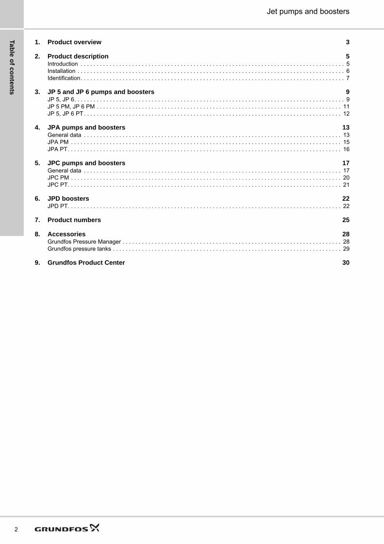
1. Product overview 3
2. Product description 5Introduction . . . . . . . . . . . . . . . . . . . . . . . . . . . . . . . . . . . . . . . . . . . . . . . . . . . . . . . . . . . . . . . . . . . . . . . . . . . . . . . . . . 5Installation . . . . . . . . . . . . . . . . . . . . . . . . . . . . . . . . . . . . . . . . . . . . . . . . . . . . . . . . . . . . . . . . . . . . . . . . . . . . . . . . . . . 6Identification. . . . . . . . . . . . . . . . . . . . . . . . . . . . . . . . . . . . . . . . . . . . . . . . . . . . . . . . . . . . . . . . . . . . . . . . . . . . . . . . . . 7
3. JP 5 and JP 6 pumps and boosters 9JP 5, JP 6. . . . . . . . . . . . . . . . . . . . . . . . . . . . . . . . . . . . . . . . . . . . . . . . . . . . . . . . . . . . . . . . . . . . . . . . . . . . . . . . . . . . 9JP 5 PM, JP 6 PM . . . . . . . . . . . . . . . . . . . . . . . . . . . . . . . . . . . . . . . . . . . . . . . . . . . . . . . . . . . . . . . . . . . . . . . . . . . . 11JP 5, JP 6 PT . . . . . . . . . . . . . . . . . . . . . . . . . . . . . . . . . . . . . . . . . . . . . . . . . . . . . . . . . . . . . . . . . . . . . . . . . . . . . . . . 12
4. JPA pumps and boosters 13General data . . . . . . . . . . . . . . . . . . . . . . . . . . . . . . . . . . . . . . . . . . . . . . . . . . . . . . . . . . . . . . . . . . . . . . . . . . . . . . . . 13JPA PM . . . . . . . . . . . . . . . . . . . . . . . . . . . . . . . . . . . . . . . . . . . . . . . . . . . . . . . . . . . . . . . . . . . . . . . . . . . . . . . . . . . . 15JPA PT. . . . . . . . . . . . . . . . . . . . . . . . . . . . . . . . . . . . . . . . . . . . . . . . . . . . . . . . . . . . . . . . . . . . . . . . . . . . . . . . . . . . . 16
5. JPC pumps and boosters 17General data . . . . . . . . . . . . . . . . . . . . . . . . . . . . . . . . . . . . . . . . . . . . . . . . . . . . . . . . . . . . . . . . . . . . . . . . . . . . . . . . 17JPC PM . . . . . . . . . . . . . . . . . . . . . . . . . . . . . . . . . . . . . . . . . . . . . . . . . . . . . . . . . . . . . . . . . . . . . . . . . . . . . . . . . . . . 20JPC PT. . . . . . . . . . . . . . . . . . . . . . . . . . . . . . . . . . . . . . . . . . . . . . . . . . . . . . . . . . . . . . . . . . . . . . . . . . . . . . . . . . . . . 21
6. JPD boosters 22JPD PT. . . . . . . . . . . . . . . . . . . . . . . . . . . . . . . . . . . . . . . . . . . . . . . . . . . . . . . . . . . . . . . . . . . . . . . . . . . . . . . . . . . . . 22
7. Product numbers 25
8. Accessories 28Grundfos Pressure Manager . . . . . . . . . . . . . . . . . . . . . . . . . . . . . . . . . . . . . . . . . . . . . . . . . . . . . . . . . . . . . . . . . . . . 28Grundfos pressure tanks . . . . . . . . . . . . . . . . . . . . . . . . . . . . . . . . . . . . . . . . . . . . . . . . . . . . . . . . . . . . . . . . . . . . . . . 29
9. Grundfos Product Center 30

Pro
du
ct
ov
erv
iew
Jet pumps and boosters 1
1. Product overview
Pump Description Technical data Page
JP 5 and JP 6 pumps and boosters
JP 5, JP 6
Self-priming pump for water supply and transfer in applications such as:• single- and two-family houses• gardens.
Maximum suction lift: 7 mMaximum head: 57 mMaximum flow rate: 5 mPump body: stainless steel
9
JP 5 PM, JP 6 PM
JP 5 or JP 6 pump with a Pressure Manager
Features• Anticycling• dry-running protection• automatic start/stop.
Maximum suction lift: 7 mMaximum head: 57 mMaximum flow rate: 5 mPump body: stainless steel
11
JP 5 PT, JP 6 PT
JP 5 or JP 6 pump with a pressure tank and pressure switch
Features• Automatic start/stop• constant water supply.
Maximum suction lift: 7 mMaximum head: 57 mMaximum flow rate: 5 mPump body: stainless steelTank: 18, 24, 60 l, horizontal
12
JPA pumps and boosters
JPA
Self-priming pump for water supply and transfer in applications such as:• single- and two-family houses• gardens• small-scale agriculture• industrial greenhouses.
Maximum suction lift: 8 mMaximum head: 62 mMaximum flow rate: 12 mPump body: cast iron
13
JPA PM
JPA pump with a PM pressure manager
Features• Anticycling• dry-running protection• automatic start/stop.
Maximum suction lift: 8 mMaximum head: 54 mMaximum flow rate: 4 mPump body: cast iron
15
JPA PT
JPA pump with a pressure tank and pressure switch. The pressure tank is available in a horizontal or vertical version.
Features• Automatic start/stop• constant water supply.
Maximum suction lift: 8 mMaximum head: 54 mMaximum flow rate: 4 mPump body: cast ironTank: 18 l vertical, 20 l horizontal
16
3

Pro
du
ct o
ve
rvie
w
4
Jet pumps and boosters1
JPC pumps and boosters
JPC
Self-priming pump for water supply and transfer in applications such as:• single- and two-family houses• gardens.
Maximum suction lift: 8 mMaximum head: 54 mMaximum flow rate: 4 mPump body: composite material
17
JPC PM
JPC pump with a PM pressure manager
Features:• Anticycling• dry-running protection• automatic start/stop.
Maximum suction lift: 8 mMaximum head: 54 mMaximum flow rate: 4 mPump body: composite material
20
JPC PT
JPC pump with a pressure tank and pressure switch
Features• Automatic start/stop• constant water supply.
Maximum suction lift: 8 mMaximum head: 54 mMaximum flow rate: 4 mPump body: compositeTank: 18 l vertical
21
JPD boosters for deep-well applications
JPD PT
Self-priming pump with a pressure tank, a pressure switch and an external ejector for deep-well applications. The booster is suitable for water supply and transfer in applications such as:• farmhouses• small-scale agriculture.
Features• Suction lift up to 27 metres• constant water supply• automatic start/stop.
Maximum suction lift: 27 mMaximum head: 62 mMaximum flow rate: 12 mPump body: cast ironTank: 18 l vertical
22
Pump Description Technical data Page

Pro
du
ct
de
sc
rip
tio
n
Jet pumps and boosters 2
2. Product description
IntroductionGrundfos offers jet pumps for a wide range of domestic applications such as water supply to single- and two-family houses, gardens and small-scale agriculture. The jet pumps ensure a constant supply of water to your home and garden. Grundfos offers four different product types which include a jet pump:
• separate jet pumps
• booster solutions which include a jet pump and a Pressure Manager
• booster solutions which include a jet pump, a pressure switch and a pressure tank
• booster solutions which include a jet pump, a pressure switch, a pressure tank and an external ejector nozzle for deep-well applications.
Jet pumpsThe jet pumps are self-priming centrifugal pumps designed for long and trouble-free operation. A jet pump has an excellent suction capacity and is self-priming thanks to the built-in ejector.
The pump is small, handy and easy to move around, which makes it suitable for a various of applications.
Fig. 1 JP 5, JP 6, JPC, JPA
BoostersThe boosters are compact systems for domestic water supply. The boosters consist of a Grundfos jet pump and a pressure control unit. The pressure control unit gives more comfort to the user, as it allows the pump to start and stop automatically according to demand.
The boosters are divided into two main groups, i.e. jet pumps with Pressure Manager and jet pumps with a pressure tank.
Booster with Pressure Manager
The Pressure Manager comes in two versions:
• a basic version, PM 1
• an advanced version, PM 2.
They both have the following features:
• anticycling
• automatic start/stop
• dry-running protection
• integrated non-return valve.
Fig. 2 JP 5/6 PM, JPA PM, JPC PM
Booster with pressure tank
The booster consists of a pressure switch, a pressure gauge and a diaphragm tank.
The pressure switch automatically starts the pump according to demand. The diaphragm tank ensures a constant water pressure in the water supply and thereby limits the number of starts in case of low water consumption or leakage loss. Furthermore, the diaphragm tank increases system comfort by compensating for pressure drops when a tap is opened, and finally it reduces problems with water hammer in the pipework.
Fig. 3 JP 5/6 PT, JPC PT, JPA PT, JPD PT
Pumped liquidsJet pumps and boosters are suitable for pumping clean, thin, non-aggressive and non-explosive liquids without solid particles or fibres. Examples of liquids:
• potable water
• rainwater.
If the pumps are used for pumping unclean liquids, such as pool water, they must subsequently be flushed with clean water. The pumps must not be used for transfer of diesel oil or other oil-containing liquids. Sand and other impurities in the water cause wear to the pump.
TM
01
45
95
35
02
- T
M0
5 5
20
5 3
41
2G
r10
45
- T
M0
6 5
41
0 4
51
5
TM
05
59
89
43
12
- T
M0
5 8
00
7 1
81
3
TM
05
59
87
43
12
-
TM
05
82
25
211
3
5
Pro
du
ct d
es
crip
tion
6
Jet pumps and boosters2
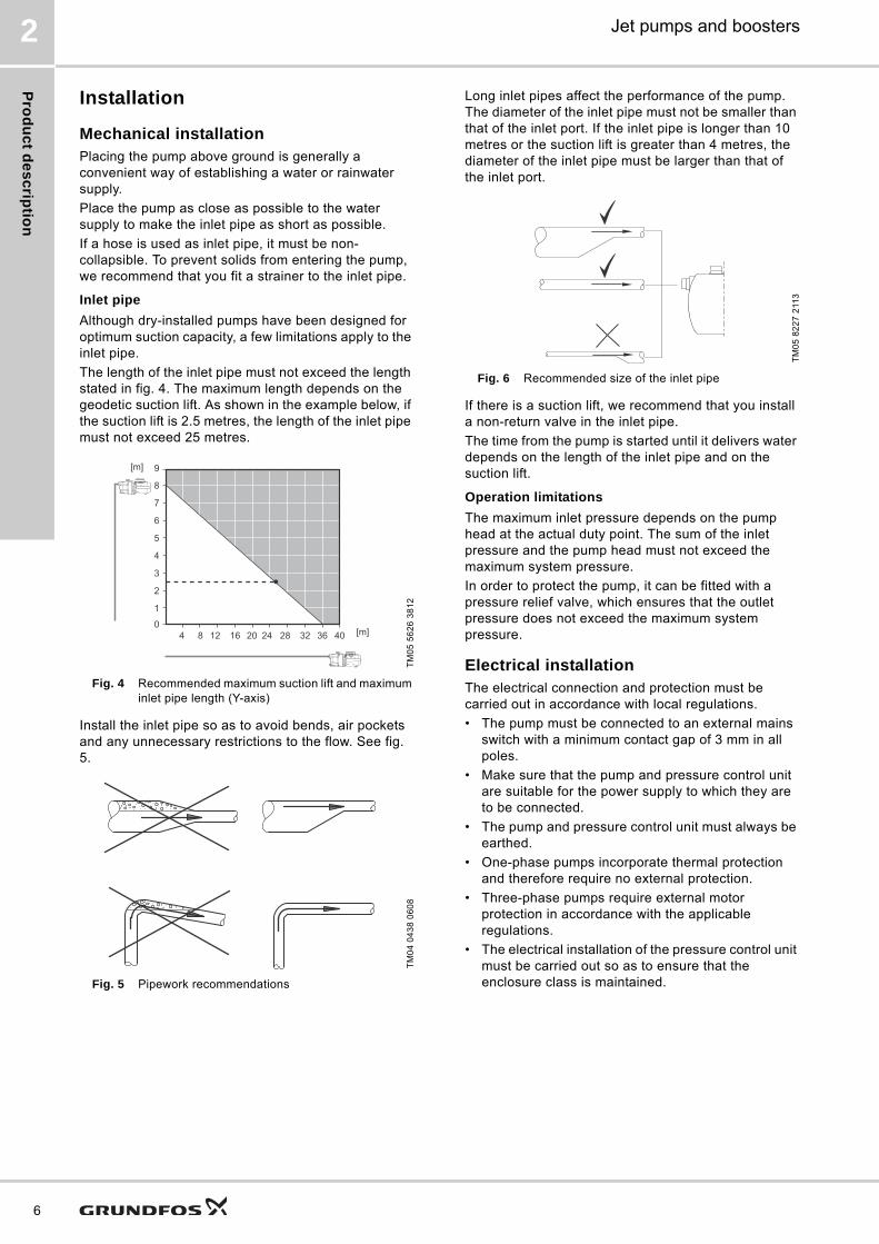
Installation
Mechanical installationPlacing the pump above ground is generally a convenient way of establishing a water or rainwater supply.
Place the pump as close as possible to the water supply to make the inlet pipe as short as possible.
If a hose is used as inlet pipe, it must be non-collapsible. To prevent solids from entering the pump, we recommend that you fit a strainer to the inlet pipe.
Inlet pipe
Although dry-installed pumps have been designed for optimum suction capacity, a few limitations apply to the inlet pipe.
The length of the inlet pipe must not exceed the length stated in fig. 4. The maximum length depends on the geodetic suction lift. As shown in the example below, if the suction lift is 2.5 metres, the length of the inlet pipe must not exceed 25 metres.
Fig. 4 Recommended maximum suction lift and maximum inlet pipe length (Y-axis)
Install the inlet pipe so as to avoid bends, air pockets and any unnecessary restrictions to the flow. See fig. 5.
Fig. 5 Pipework recommendations
Long inlet pipes affect the performance of the pump. The diameter of the inlet pipe must not be smaller than that of the inlet port. If the inlet pipe is longer than 10 metres or the suction lift is greater than 4 metres, the diameter of the inlet pipe must be larger than that of the inlet port.
Fig. 6 Recommended size of the inlet pipe
If there is a suction lift, we recommend that you install a non-return valve in the inlet pipe.
The time from the pump is started until it delivers water depends on the length of the inlet pipe and on the suction lift.
Operation limitations
The maximum inlet pressure depends on the pump head at the actual duty point. The sum of the inlet pressure and the pump head must not exceed the maximum system pressure.
In order to protect the pump, it can be fitted with a pressure relief valve, which ensures that the outlet pressure does not exceed the maximum system pressure.
Electrical installationThe electrical connection and protection must be carried out in accordance with local regulations.
• The pump must be connected to an external mains switch with a minimum contact gap of 3 mm in all poles.
• Make sure that the pump and pressure control unit are suitable for the power supply to which they are to be connected.
• The pump and pressure control unit must always be earthed.
• One-phase pumps incorporate thermal protection and therefore require no external protection.
• Three-phase pumps require external motor protection in accordance with the applicable regulations.
• The electrical installation of the pressure control unit must be carried out so as to ensure that the enclosure class is maintained.
TM
05
56
26
38
12
TM
04
04
38
06
08
0
1
4 8 12 16 20 24 28 32 36 40
2
3
4
5
6
7
8
9[m]
[m]
TM
05
82
27
211
3
Pro
du
ct
de
sc
rip
tio
n
Jet pumps and boosters 2
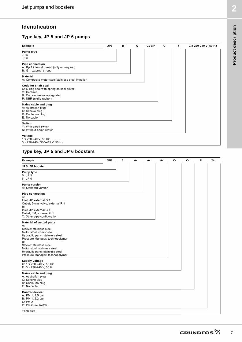
Identification
Type key, JP 5 and JP 6 pumps
Type key, JP 5 and JP 6 boosters
Example JP5 B- A- CVBP- C- Y 1 x 220-240 V, 50 Hz
Pump typeJP 5JP 6
Pipe connectionA: Rp 1 internal thread (only on request)B: G 1 external thread
MaterialA: Composite motor stool/stainless-steel impeller
Code for shaft sealC: O-ring seal with spring as seal driverV: CeramicB: Carbon, resin-impregnatedP: NBR (nitrile rubber)
Mains cable and plugA: Australian plugC: Schuko plugD: Cable, no plugE: No cable
SwitchY: With on/off switchN: Without on/off switch
Voltage1 x 220-240 V, 50 Hz3 x 220-240 / 380-415 V, 50 Hz
Example JPB 5 A- A- A- C- C- P 24L
JPB: JP booster
Pump type5: JP 56: JP 6
Pump versionA: Standard version
Pipe connectionA:Inlet, JP, external G 1Outlet, 5-way valve, external R 1B:Inlet, JP, external G 1Outlet, PM, external G 1X: Other pipe configuration
Material of wetted partsA:Sleeve: stainless steelMotor stool: compositeHydraulic parts: stainless steelPressure Manager: technopolymerB:Sleeve: stainless steelMotor stool: stainless steelHydraulic parts: stainless steelPressure Manager: technopolymer
Supply voltageC: 1 x 220-240 V, 50 HzF: 3 x 220-240 V, 50 Hz
Mains cable and plugA: Australian plugC: Schuko plugD: Cable, no plugE: No cable
Control deviceA: PM 1, 1.5 barB: PM 1, 2.2 barC: PM 2P: Pressure switch
Tank size
7
Pro
du
ct d
es
crip
tion
8
Jet pumps and boosters2
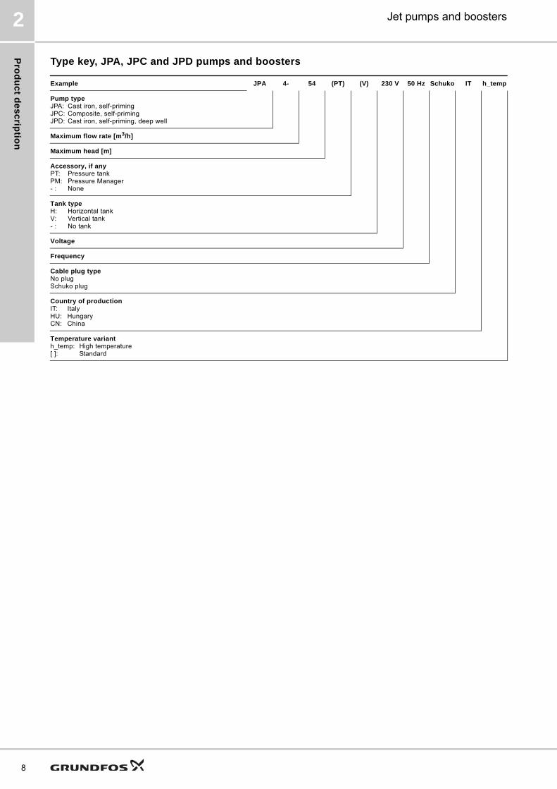
Type key, JPA, JPC and JPD pumps and boosters
Example JPA 4- 54 (PT) (V) 230 V 50 Hz Schuko IT h_temp
Pump typeJPA: Cast iron, self-primingJPC: Composite, self-primingJPD: Cast iron, self-priming, deep well
Maximum flow rate [m3/h]
Maximum head [m]
Accessory, if anyPT: Pressure tankPM: Pressure Manager- : None
Tank typeH: Horizontal tankV: Vertical tank- : No tank
Voltage
Frequency
Cable plug typeNo plugSchuko plug
Country of productionIT: ItalyHU: HungaryCN: China
Temperature varianth_temp: High temperature[ ]: Standard
JP
5 a
nd
JP
6 p
um
ps
an
d b
oo
ste
rs
Jet pumps and boosters 3
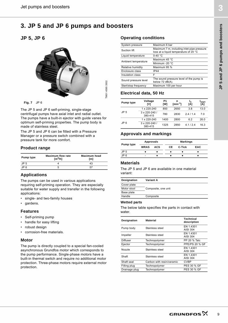
3. JP 5 and JP 6 pumps and boosters
JP 5, JP 6
Fig. 7 JP 6
The JP 5 and JP 6 self-priming, single-stage centrifugal pumps have axial inlet and radial outlet. The pumps have a built-in ejector with guide vanes for optimum self-priming properties. The pump body is made of stainless steel.
The JP 5 and JP 6 can be fitted with a Pressure Manager or a pressure switch combined with a pressure tank for more comfort.
Product range
ApplicationsThe pumps can be used in various applications requiring self-priming operation. They are especially suitable for water supply and transfer in the following applications:
• single- and two-family houses
• gardens.
Features• Self-priming pump
• handle for easy lifting
• robust design
• corrosion-free materials.
MotorThe pump is directly coupled to a special fan-cooled asynchronous Grundfos motor which corresponds to the pump performance. Single-phase motors have a built-in thermal switch and require no additional motor protection. Three-phase motors require external motor protection.
Operating conditions
Electrical data, 50 Hz
Approvals and markings
MaterialsThe JP 5 and JP 6 are available in one material variant:
Wetted parts
The below table specifies the parts in contact with water.
TM
01
45
95
35
02
Pump typeMaximum flow rate
[m3/h]Maximum head
[m]
JP 5 4 43
JP 6 5 57
System pressure Maximum 6 bar
Suction liftMaximum 7 m, including inlet-pipe pressure loss at a liquid temperature of 20 °C
Liquid temperature 0-40 °C
Ambient temperatureMaximum 45 °C
Minimum -20 °C
Relative humidity Maximum 95 %
Enclosure class IP44
Insulation class F
Sound pressure levelThe sound pressure level of the pump is below 72 dB(A).
Start/stop frequency Maximum 100 per hour
Pump typeVoltage
[V]P1[W]
n[min-1]
In[A]
Istart[A]
JP 51 x 220-240 850 2650 3.8 13.0
3 x 220-240 / 380-415
780 2830 2.4 / 1.4 7.0
JP 61 x 220-240 1400 2800 6.2 26.0
3 x 220-240 / 380-415
1325 2850 4.1 / 2.4 16.3
Pump typeApprovals Markings
WRAS ACS CE C-Tick EAC
JP 5 ● ● ● ● ●
JP 6 - ● ● ● ●
Designation Variant A
Cover plate
Composite, one unitMotor stool
Base plate
Handle Composite
Designation MaterialTechnical description
Pump body Stainless steelEN 1.4301AISI 304
Impeller Stainless steelEN 1.4301AISI 304
Diffuser Technopolymer PP 20 % Talc
Ejector Technopolymer PPE/PS 20 % GF
Nozzle Stainless steelEN 1.4301AISI 304
Shaft Stainless steelEN 1.4301AISI 304
Shaft seal Carbon with resin/ceramic CVBP
Filling plug Technopolymer PES 30 % GF
Drainage plug Technopolymer PES 30 % GF
9
JP
5 a
nd
JP
6 p
um
ps
an
d b
oo
ste
rs
10
Jet pumps and boosters3
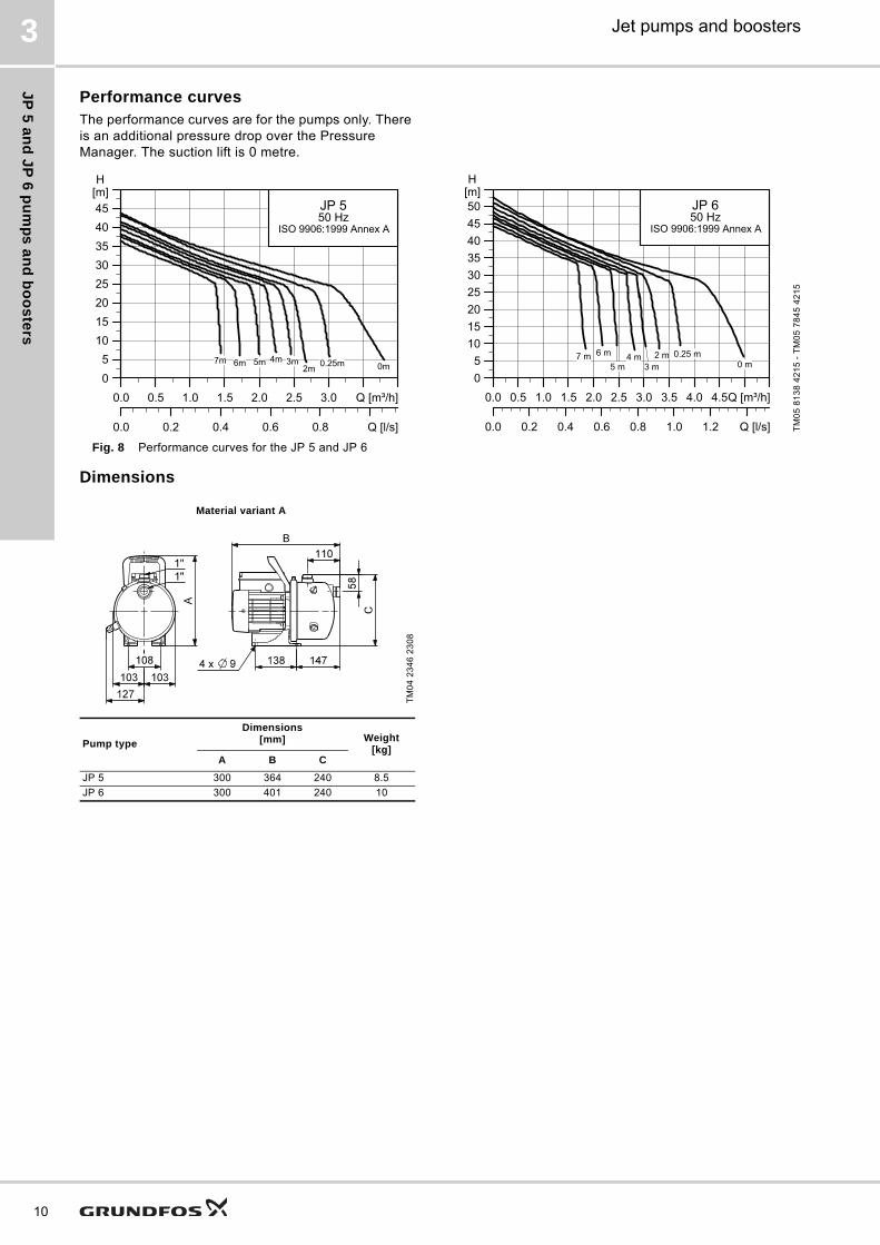
Performance curvesThe performance curves are for the pumps only. There is an additional pressure drop over the Pressure Manager. The suction lift is 0 metre.
Fig. 8 Performance curves for the JP 5 and JP 6
Dimensions
TM
05
81
38
42
15
- T
M0
5 7
84
5 4
21
5
��� ��� ��� ��� ��� ��� ��� ��� ����
����������������
���
��� ��� ��� ��� ��� �� ��
���
���������������� ����!
�����������������"�
��� ��� ��� ��� ��� ��� ��� ��� ��� ������ ����
������������������
���
��� ��� ��� ��� ��� ��� ��� �� ��
���
���������������� ����!
"� ����
����
�� �������
Material variant A
TM
04
23
46
23
08
Pump type
Dimensions[mm] Weight
[kg]A B C
JP 5 300 364 240 8.5
JP 6 300 401 240 10

JP
5 a
nd
JP
6 p
um
ps
an
d b
oo
ste
rs
Jet pumps and boosters 3
JP 5 PM, JP 6 PM
Fig. 9 JP PM 1 (left) and JP PM 2 (right)
The compact JP 5 PM and JP 6 PM boosters consist of a JP 5 or JP 6 pump, material variant A, and a Grundfos Pressure Manager.
The Pressure Manager comes in two versions:
• a basic version, PM 1
• an advanced version, PM 2.
To reduce the number of starts/stops, an external tank can be installed. See GT-U bladder tanks on page 29 and GT-H diaphragm tanks on page 29.
Features• Anticycling
• dry-running protection
• automatic start/stop:JP 5 PM 1: start pressure of 1.5 bar.JP 6 PM 1: start pressure of 2.2 bar.JP 5, JP 6 PM 2: adjustable start pressure between 1.5 and 5.5 bar.
• maximum continuous operating time (PM 2 only).
For a complete list of features, see Accessories on page 28.
Electrical dataThe JP PM 1 and JP PM 2 come with single-phase motors. See Electrical data, 50 Hz on page 9.
Approvals and markings
Wetted parts of the Pressure ManagerThe below table specifies the parts in contact with water.
Dimensions
TM
05
59
89
43
12
- T
M0
5 5
98
8 4
31
2
Approvals Markings
WRAS ACS CE C-Tick EAC
- - ● ● ●
Designation Material Technical description
Housing Technopolymer PP 30 % GF
Shutter Technopolymer PPO 20 % GF
O-ring Rubber NBR
Cover magnet Technopolymer PPO 20 % GF
Fitting, 1" Technopolymer PPO 30 % GF
Spring Stainless steel EN 1.4305 AISI 303
Diaphragm Butyl Foodgum 55 N/B
TM
05
59
70
43
12
Pump type
Dimensions[mm] Weight
[kg]A B C D
JP 5 PM 364 206 420 182 8.5
JP 6 PM 401 206 420 182 10
11

JP
5 a
nd
JP
6 p
um
ps
an
d b
oo
ste
rs
12
Jet pumps and boosters3
JP 5, JP 6 PT
Fig. 10 JP PT
The compact JP 5 PT and JP 6 PT boosters consist of a JP 5 or JP 6 pump, material variant A, a pressure switch and a diaphragm tank.
The pressure switch automatically starts the pump according to demand.
The diaphragm tank ensures a controlled pressure in the water supply and thereby limits the switching frequency of the pump in case of low water consumption or leakage loss. Furthermore, the diaphragm tank increases system comfort by compensating for pressure drops when a tap is opened, and finally it reduces problems with water hammer in the pipework.
The JP PT is available with the following diaphragm tanks:
• 18-litre vertical tank
• 24-litre horizontal tank
• 60-litre horizontal tank.
Features• Automatic start/stop at 2.2 and 3.3 bar.
• constant water supply.
Approvals and markings
Wetted partsThe below tables specify the parts in contact with water.
Pressure switch
Pressure tank
DimensionsThe JP PT is available with different tank sizes. The booster design depends on the size of the selected tank.
TM
05
59
87
43
12
Approvals Markings
WRAS ACS CE C-Tick EAC
- - ● - ●
Designation MaterialTechnical description
Pressure sensor Zinc alloy NF EN 12844
5-way valve Brass MSG58
Pressure gauge Brass
Pressure tank Rubber/stainless steel
Armed rubber hose Rubber/stainless steel
TM
05
59
72
43
12
Pump typeTank size
[l]
Dimensions[mm] Weight
[kg]A B C D
JP 5, JP 6 18 668 275 475 494 20
JP 5, JP 6 24 680 291 510 506 21
JP 5, JP 6 60 786 390 580 612 26

JP
A p
um
ps
an
d b
oo
ste
rs
Jet pumps and boosters 4
4. JPA pumps and boosters
General data
Fig. 11 JPA pumps
The JPA self-priming, single-stage centrifugal pump has a cast iron body as well as axial inlet and radial outlet. The pump has a built-in ejector with guide vanes for optimum self-priming properties.
The JPA can be fitted with a pressure tank for more comfort.
Product range
ApplicationsThe pumps can be used in various applications where self-priming is needed. They are especially suitable for water supply and transfer in the following applications:
• single- or two-family houses
• gardens.
The big versions can be used in the following applications as well:
• water transfer
• small-scale agriculture
• industrial greenhouses.
Features• Self-priming
• robust design
• corrosion-resistant materials.
MotorThe rotor is mounted on oversize, sealed greased-for-life ball bearings ensuring silent running and long life. Single-phase motors have built-in thermal and current protection and require no additional motor protection.
Operating conditions
Electrical data, 50 Hz
Approvals and markings
Wetted partsThe below table specifies the parts in contact with water.
* JPA 3-42, 4-47, 4-54.
TM
06
54
06
- T
M0
6 5
41
0 -
TM
06
54
11 4
51
5
Pump typeMaximum flow rate
[m3/h]Maximum head
[m]
JPA, JPA PT, JPA PM
3 42
4 47
4 54
JPA
5 61
8 62
12 41
12 51
System pressure Maximum 8 bar
Flow rate 0.6 - 10.5 m3/h
Suction liftMaximum 8 m, including inlet-pipe pressure loss at a liquid temperature of 20 °C
Liquid temperature0-35 °C (domestic use)0-40 °C (other use)
Ambient temperature Maximum 40 °C
Relative humidity Maximum 95 %
Enclosure class IP44
Insulation class F
Sound pressure levelThe sound pressure level of the pump is below 77 dB(A).
Start/stop frequency Maximum 20 per hour
Pump typeVoltage
[V]P1 [W]
Speed[min-1]
In[A]
JPA 3-42 1 x 220-240 720 2850 3.12
JPA 4-47 1 x 220-240 850 2750 3.8
JPA 4-54 1 x 220-240 1130 2800 5.1
JPA 5-61 1 x 220-240 1600 2800 7.2
JPA 8-62 1 x 220-240 2200 2800 10
JPA 12-41 1 x 220-240 2000 2800 9
JPA 12-51 1 x 220-240 2700 2800 12
Approvals Markings
WRAS ACS CE C-Tick EAC
- - ● ● ●
Designation MaterialTechnical description
Pump body Cast iron EN-GJL-200
Motor stoolCast ironDie-cast aluminium*
EN-GJL-200EN AB 46100
Impeller Technopolymer Noryl GFN 2
Diffuser Technopolymer Noryl GFN 2
Diffuser ring Stainless steelEN 1.4401AISI 316
Venturi tubeTechnopolymerRubber
Noryl GFN 2
Shaft Stainless steelEN 1.4305AISI 303
Shaft seal Carbon with resin/ceramic BBQP
Filling/drainage plug Technopolymer PPE 20 % GF
Filling/drainage plug gasket
Rubber NBR
Back plate Stainless steelEN 1.4301AISI 304
13

JP
A p
um
ps
an
d b
oo
ste
rs
14
Jet pumps and boosters4
Performance curves
Fig. 12 Performance curves for JPA
Note: For the JPA PM, there is an additional pressure drop over the Pressure Manager.
Dimensions
Fig. 13 JPA 3-42, 4-47, 4-54
Fig. 14 JPA 5-61, 8-62
Fig. 15 JPA 12-41, JPA 12-51
TM
02
89
36
50
15
� � � � � � � " � � �� ��� ����
����������������������
���
��� ��� ��� ��� ��� ��� ��� �� ��
������!
���������������� �
�#��
�#��
��#��
��#��
�#��
�#�"�#��
TM
06
52
67
42
15
Pump type
Dimensions[mm] Weight
[kg]A A1 H
JPA 3-42 396 391 200 10.5
JPA 4-47 396 391 200 11
JPA 4-54 417 411 210 13
TM
06
52
68
42
15
Pump type
Dimensions[mm] Weight
[kg]A B
JPA 5-61 558 217 29
JPA 8-62 632 218 33
TM
06
52
69
42
15
Pump type
Dimensions[mm] Weight
[kg]A H
JPA 12-41 521 225 26
JPA 12-51 595 230 29

JP
A p
um
ps
an
d b
oo
ste
rs
Jet pumps and boosters 4
JPA PM
Fig. 16 JPA PM
The compact JPA PM booster consists of a JPA pump and a Grundfos Pressure Manager.
The Pressure Manager comes in the PM 1 version.
To reduce the number of starts/stops, an external tank can be installed. See GT-U bladder tanks on page 29 and GT-H diaphragm tanks on page 29.
Features• Anticycling
• dry-running protection
• automatic start/stop.
Wetted parts of the Pressure ManagerThe below table specifies the parts in contact with water.
Dimensions
JPA PM
Fig. 17 JPA PM
TM
06
67
03
22
16
Designation Material Technical description
Housing Technopolymer PP 30 % GF
Shutter Technopolymer PPO 20 % GF
O-ring Rubber NBR
Cover magnet Technopolymer PPO 20 % GF
Fitting 1" Technopolymer PPO 30 % GF
Spring Stainless steel EN 1.4305 AISI 303
Diaphragm Butyl Foodgum 55 N/BT
M0
6 7
40
7 3
41
6
TypeDimensions [mm] Weight
[kg]H L A
JPA 3-42 PM 332 396 180 10
JPA 4-47 PM 332 396 180 11
JPA 4-54 PM 332 417 180 13
H
L A
15

JP
A p
um
ps
an
d b
oo
ste
rs
16
Jet pumps and boosters4
JPA PT
Fig. 18 JPA PT-V (left) and JPA PT-H (right)
The JPA PT booster consists of a JPA pump, a pressure switch, a pressure gauge and a diaphragm tank.
The pressure switch automatically starts the pump according to demand. The diaphragm tank ensures a constant water pressure in the water supply and thereby limits the switching frequency of the pump in case of low water consumption or leakage loss. Furthermore, the diaphragm tank increases system comfort by compensating for pressure drops when a tap is opened, and finally it reduces problems with water hammer in the pipework.
The JPA PT is available with the following tanks:
• 20-litre horizontal tank (JPA PT-H)
• 18-litre vertical tank (JPA PT-V).
Features• Automatic start/stop
• constant water supply
Wetted partsThe below tables specify the parts in contact with water.
Pressure switch
Pressure tank
Dimensions
JPA PT-H
Fig. 19 JPA PT-H
JPA PT-V
Fig. 20 JPA 4-47, 4-54 PT-V
Fig. 21 JPA 5-61, 8-62 PT-V
TM
06
54
08
45
15
- T
M0
6 5
40
9 4
51
5
Designation MaterialTechnical description
Pressure sensorStainless steel
EN 1.4301AISI 304
Rubber TIMO 70
5-way valve Brass MSG58
Pressure gauge Brass
Tank Rubber/stainless steel
Armed rubber hose Rubber/stainless steel
TM
06
52
72
42
15
TypeDimensions [mm] Weight
[kg]A1 H1
JPA 3-42 PT-H 391 200 17
JPA 4-47 PT-H 391 200 17.5
JPA 4-54 PT-H 411 210 19
TM
06
53
54
44
15
TypeDimensions [mm]
A L L1 H
JPA 4-47 PT-V 587 396 416 327
JPA 4-54 PT-V 586 411 436 324T
M0
65
35
5 4
41
5
TypeDimensions [mm]
A L H
JPA 5-61 PT-V 264 563 662
JPA 8-62 PT-V 264 637 662

JP
C p
um
ps
an
d b
oo
ste
rs
Jet pumps and boosters 5
5. JPC pumps and boosters
General data
Fig. 22 JPC
The JPC self-priming, single-stage centrifugal pump has a composite body as well as axial inlet and radial outlet. The pump has a built-in ejector with guide vanes for optimum self-priming properties.
Product range
ApplicationsThe pumps can be used in various applications where self-priming is needed. They are especially suitable for water supply and transfer in the following applications:
• single- and two-family houses
• gardens.
Features• Self-priming
• robust design
• corrosion-free materials.
MotorThe rotor is mounted on oversized, sealed, greased-for-life ball bearings to ensure silent running and long life. Single-phase motors have built-in thermal and current protection and require no additional motor protection.
Operating conditions
* h_temp variants only
Electrical data, 50 Hz
Electrical data, 60 Hz
TM
05
50
91
32
12
Pump typeMaximum flow rate
[m3/h]Maximum head
[m]
JPC, JPC PM, JPC PT
3 42
4 47
4 54
5 48
System pressure Maximum 8 bar
Suction liftMaximum 8 m, including inlet-pipe pressure loss at a liquid temperature of 20 °C
Liquid temperature 0-35 °C (0-60 °C*)
Ambient temperature Maximum 40 °C (maximum 55 °C*)
Relative humidity Maximum 95 %
Enclosure class IP44
Insulation class F
Sound pressure level
Maximum sound pressure level of the pump:JPC 3-42: 82.9 dBJPC 4-47: 84.8 dBJPC 4-54: 88.0 dB
Start/stop frequency Maximum 20 per hour
Pump typeVoltage
[V]P1[W]
n[min-1]
In[A]
Istart[A]
JPC 3-42 1 x 220-240 720 2900 3.12 8.54
JPC 4-47 1 x 220-240 850 2900 3.8 11.27
JPC 4-54 1 x 220-240 1130 2900 5.1 17.8
JPC 5-48 1 x 220-240 1490 2900 6.6 26.4
Pump typeVoltage
[V]P1[W]
P2[W]
n[min-1]
In[A]
Istart[A]
JPC 3-421 x 110-120 730 450 3400 6.6 22.4
1 x 220-240 700 450 3400 4 11.3
JPC 4-471 x 110-120 900 600 3400 8 26.8
1 x 220-240 880 600 3400 3.9 13.2
JPC 4-541 x 110-120 1100 750 3400 9.7 47.5
1 x 220-240 1100 750 3400 5 23.9
JPC 5-481 x 110-120 1470 1000 3400 13.4 53.6
1 x 220-240 1450 1000 3400 7.6 30.4
17

JP
C p
um
ps
an
d b
oo
ste
rs
18
Jet pumps and boosters5
Approvals and markings
MaterialsThe motor stool is made of die-cast aluminium.
Wetted parts
The below table specifies the parts in contact with water.
* h_temp variants only
Approvals Markings
WRAS ACS CE C-Tick EAC
- - ● ● ●
Designation MaterialTechnical description
Pump body TechnopolymerPP 30 % GFPA 66 GF 30*
Impeller TechnopolymerPPE 20 % GFPA 66 GF 30*brass
Diffuser TechnopolymerPPE 20 % GFPA 66 GF 30*
Diffuser ring Stainless steelEN 1.4401AISI 316
Venturi tubeTechnopolymerRubber
PPE + 20 % GFPA 66 GF 30*NBR
Seal housing Rubber NBR
Shaft Stainless steelEN 1.4305AISI 303
Shaft seal Carbon with resin/ceramic CBBXP
Filling plug TechnopolymerPPE 20 % GFPA 66 GF 30*
Filling plug gasket Rubber NBR
Drainage plug TechnopolymerPPE 20 % GFPA 66 GF 30*
Drainage plug gasket Rubber NBR
Mechanical seal disc Stainless steelEN 1.4301AISI 304

JP
C p
um
ps
an
d b
oo
ste
rs
Jet pumps and boosters 5
Performance curves
Fig. 23 Performance curves for the JPC 3-42, JPC 4-47, JPC 4-54 and JPC 5-48
Note: For the JPC PM and JPC PT, there is an additional pressure drop over the Pressure Manager and pressure switch.
Dimensions
Fig. 24 JPC
TM
06
36
85
42
15
- T
M0
6 3
68
6 4
21
5
��� ��� ��� ��� ��� ��� ��� ��� ��� ��� ����
������������������
���
��� ��� ��� ��� ��� ��� �� ��
��$
���������������� ����!
��$�#��
��$�#�"
��$�#��
��� ��� ��� ��� ��� ��� ��� ��� ��� ��� ����
������������������
���
��� ��� ��� ��� ��� ��� ����� ��
��$
���������������� ����!
��$�#��
��$�#�"
��$�#��
TM
05
56
05
37
12
Pump type [V]
Dimensions[mm] Weight
[kg]A B H
JPC 3-42115 410 198 200 8
230 410 171 200 8
JPC 4-47115 410 198 200 9.5
230 410 171 200 9.5
JPC 4-54115 430 206 210 10.5
230 430 171 210 10.5
JPC 5-48115 426 171 210 10.5
230 426 171 210 10.5
14
4
19

JP
C p
um
ps
an
d b
oo
ste
rs
20
Jet pumps and boosters5
JPC PM
Fig. 25 JPC PM
The compact JPC PM booster consists of a JPA pump and a Grundfos Pressure Manager.
The Pressure Manager comes in the PM 1 version.
To reduce the number of starts/stops, an external tank can be installed. See GT-U bladder tanks on page GT-U bladder tanks and GT-H diaphragm tanks on page 29.
Features• Anticycling
• dry-running protection
• automatic start/stop.
Wetted parts of the Pressure ManagerThe below table specifies the parts in contact with water.
Dimensions
JPC PM
Fig. 26 JPC PM
TM
05
80
07
22
16
Designation Material Technical description
Housing Technopolymer PP 30 % GF
Shutter Technopolymer PPO 20 % GF
O-ring Rubber NBR
Cover magnet Technopolymer PPO 20 % GF
Fitting 1" Technopolymer PPO 30 % GF
Spring Stainless steel EN 1.4305 AISI 303
Diaphragm Butyl Foodgum 55 N/BT
M0
6 7
40
7 3
41
6
TypeDimensions [mm] Weight
[kg]H L A
JPC 3-42 PM 349 407 175 10
JPC 4-47 PM 349 407 175 11
JPC 4-54 PM 359 407 195 13

JP
C p
um
ps
an
d b
oo
ste
rs
Jet pumps and boosters 5
JPC PT
Fig. 27 JPC PT
The JPC PT booster consists of a JPC pump, a pressure switch, a pressure gauge and a diaphragm tank.
The pressure switch allows the pump to start and stop automatically according to demand.
The diaphragm tank ensures a controlled pressure in the water supply and thereby limits the switching frequency of the pump in case of low water consumption or leakage loss. Furthermore, the diaphragm tank increases system comfort by compensating for pressure drops when a tap is opened, and finally it reduces problems with water hammer in the pipework.
The JPC PT is available with an 18-litre vertical diaphragm tank.
Features• Constant water supply
• automatic start/stop.
Wetted partsThe below tables specify the parts in contact with water.
Pressure switch
Pressure tank
Dimensions
TM
05
82
25
211
3
Designation MaterialTechnical description
Pressure sensorStainless steel
EN 1.4301AISI 304
Rubber TIMO 70
5-way valve Brass MSG58
Pressure gauge Brass
Tank Rubber/steel Butyl
TM
05
87
52
26
13
Pump typeDimensions [mm] Weight
[kg]A L H
JPC 3-42 PT 290 430 632 15
JPC 4-47 PT 290 430 632 15
JPC 4-54 PT 290 430 632 17
21
JP
D b
oo
ste
rs
22
Jet pumps and boosters6
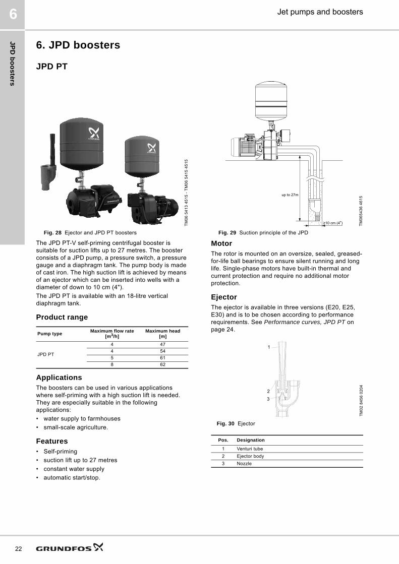
6. JPD boosters
JPD PT
The JPD PT-V self-priming centrifugal booster is suitable for suction lifts up to 27 metres. The booster consists of a JPD pump, a pressure switch, a pressure gauge and a diaphragm tank. The pump body is made of cast iron. The high suction lift is achieved by means of an ejector which can be inserted into wells with a diameter of down to 10 cm (4").
The JPD PT is available with an 18-litre vertical diaphragm tank.
Product range
ApplicationsThe boosters can be used in various applications where self-priming with a high suction lift is needed. They are especially suitable in the following applications:
• water supply to farmhouses
• small-scale agriculture.
Features• Self-priming
• suction lift up to 27 metres
• constant water supply
• automatic start/stop.
MotorThe rotor is mounted on an oversize, sealed, greased-for-life ball bearings to ensure silent running and long life. Single-phase motors have built-in thermal and current protection and require no additional motor protection.
EjectorThe ejector is available in three versions (E20, E25, E30) and is to be chosen according to performance requirements. See Performance curves, JPD PT on page 24.
Fig. 30 Ejector
TM
06
54
13
45
15
- T
M0
6 5
41
5 4
51
5
TM
06
54
36
46
15
Fig. 28 Ejector and JPD PT boosters Fig. 29 Suction principle of the JPD
up to 27m
")
Pump typeMaximum flow rate
[m3/h]Maximum head
[m]
JPD PT
4 47
4 54
5 61
8 62T
M0
2 8
45
6 0
20
4
Pos. Designation
1 Venturi tube
2 Ejector body
3 Nozzle
8
2
9
1
3
2
JP
D b
oo
ste
rs
Jet pumps and boosters 6
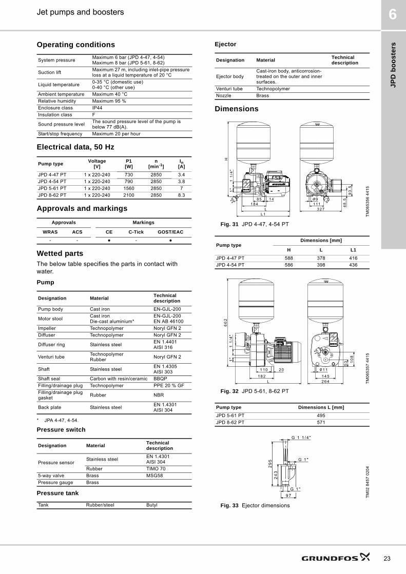
Operating conditions
Electrical data, 50 Hz
Approvals and markings
Wetted partsThe below table specifies the parts in contact with water.
Pump
* JPA 4-47, 4-54.
Pressure switch
Pressure tank
Ejector
Dimensions
Fig. 31 JPD 4-47, 4-54 PT
Fig. 32 JPD 5-61, 8-62 PT
Fig. 33 Ejector dimensions
System pressureMaximum 6 bar (JPD 4-47, 4-54)Maximum 8 bar (JPD 5-61, 8-62)
Suction liftMaximum 27 m, including inlet-pipe pressure loss at a liquid temperature of 20 °C
Liquid temperature0-35 °C (domestic use)0-40 °C (other use)
Ambient temperature Maximum 40 °C
Relative humidity Maximum 95 %
Enclosure class IP44
Insulation class F
Sound pressure levelThe sound pressure level of the pump is below 77 dB(A).
Start/stop frequency Maximum 20 per hour
Pump typeVoltage
[V]P1[W]
n[min-1]
In[A]
JPD 4-47 PT 1 x 220-240 730 2850 3.4
JPD 4-54 PT 1 x 220-240 790 2850 3.8
JPD 5-61 PT 1 x 220-240 1560 2850 7
JPD 8-62 PT 1 x 220-240 2100 2850 8.3
Approvals Markings
WRAS ACS CE C-Tick GOST/EAC
- - ● - ●
Designation MaterialTechnical description
Pump body Cast iron EN-GJL-200
Motor stoolCast ironDie-cast aluminium*
EN-GJL-200EN AB 46100
Impeller Technopolymer Noryl GFN 2
Diffuser Technopolymer Noryl GFN 2
Diffuser ring Stainless steelEN 1.4401AISI 316
Venturi tubeTechnopolymerRubber
Noryl GFN 2
Shaft Stainless steelEN 1.4305AISI 303
Shaft seal Carbon with resin/ceramic BBQP
Filling/drainage plug Technopolymer PPE 20 % GF
Filling/drainage plug gasket
Rubber NBR
Back plate Stainless steelEN 1.4301AISI 304
Designation MaterialTechnical description
Pressure sensorStainless steel
EN 1.4301AISI 304
Rubber TIMO 70
5-way valve Brass MSG58
Pressure gauge Brass
Tank Rubber/steel Butyl
Designation MaterialTechnical description
Ejector bodyCast-iron body, anticorrosion-treated on the outer and inner surfaces.
Venturi tube Technopolymer
Nozzle Brass
TM
06
53
56
44
15
Pump typeDimensions [mm]
H L L1
JPD 4-47 PT 588 378 416
JPD 4-54 PT 586 398 436
TM
06
53
57
44
15
Pump type Dimensions L [mm]
JPD 5-61 PT 495
JPD 8-62 PT 571
TM
02
84
57
02
04
23

JP
D b
oo
ste
rs
24
Jet pumps and boosters6
Performance curves, JPD PT
TM
06
52
42
42
15
TM
06
52
43
42
15
M0
65
24
4 4
21
5
TM
06
52
45
42
15
TM
06
52
46
42
15
TM
06
52
47
42
15
TM
06
52
48
42
15
��� ��� ��� ��� ��� ��� ��� ��� ��� ��� ���
��
��
��
��
��
��
���
��� ��� ��� ��� ��� ��� �� ��
���%&'()�*�+'�
��,�#�"-��
��,�#�"-��
��,�#��-��
��,�#��-��
��,�#��-��9 m suction lift
��� ��� ��� ��� ��� ��� ��� ��� ��� ���
��
��
��
��
��
���
��� ��� ��� ��� ��� ��� �� ��
����%&'()�*�+'�
��,�#�"-��
��,�#�"-��
��,�#��-��
��,�#��-��
��,�#��-��
��,�#��-��
12 m suction lift
��� ��� ��� ��� ��� ��� ��� ���
��
��
��
��
��
��
���
��� ��� ��� ��� ��� �� ��
����%&'()�*�+'�
��,�#�"-�� ��,�#�"-����,�#��-��
��,�#��-��
��,�#��-��
��,�#��-��
��,�#��-��
��,�#��-��15 m suction lift
��� ��� ��� ��� ��� ��� ��� ��� ���
��
��
��
��
��
��
���
��� ��� ��� ��� �� ��
����%&'()�*�+'�
��,�#��-��
��,�#��-��
��,�#��-��
��,�#��-��
��,�#��-�� 18 m suction lift
��� ��� ��� ��� ��� ��� ��� ��� ��� ��� ��� ��� ���
��
��
��
��
��
��
"�
���
��� ��� ��� ��� ��� ��� ��� �� ��
����%&'()�*�+'�
��,�#��-��
��,�#��-��
��,�#��-��
��,�#��-��
��,�#��-�� 21 m suction lift
��� ��� ��� ��� ��� ��� ��� ��� ��� ��� ��� ���
��
��
��
��
��
��
"�
���
��� ��� ��� ��� ��� ��� �� ��
����%&'()�*�+'�
��,�#��-��
��,�#��-��
��,�#��-�� 24 m suction lift
��� ��� ��� ��� ��� ��� ��� ��� ��� ���
��
��
��
��
��
��
"�
���
��� ��� ��� ��� ��� �� ��
�"��%&'()�*�+'�
��,�#��-��
��,�#��-�� 27 m suction lift
Pro
du
ct
nu
mb
ers
Jet pumps and boosters 7
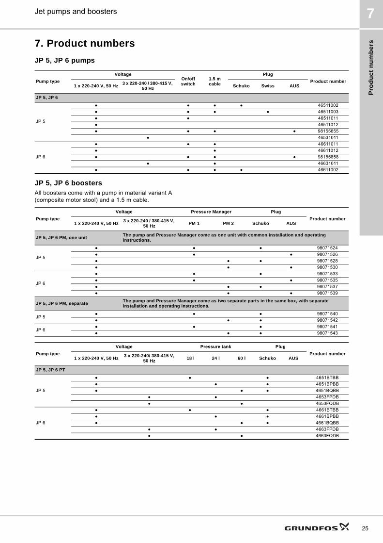
7. Product numbers
JP 5, JP 6 pumps
JP 5, JP 6 boostersAll boosters come with a pump in material variant A (composite motor stool) and a 1.5 m cable.
Pump type
VoltageOn/off switch
1.5 m cable
Plug
Product number1 x 220-240 V, 50 Hz
3 x 220-240 / 380-415 V, 50 Hz
Schuko Swiss AUS
JP 5, JP 6
JP 5
● ● ● ● 46511002
● ● ● ● 46511003
● ● 46511011
● 46511012
● ● ● ● 98155855
● 46531011
JP 6
● ● ● 46611011
● ● 46611012
● ● ● ● 98155858
● ● 46631011
● ● ● ● 46611002
Pump type
Voltage Pressure Manager Plug
Product number1 x 220-240 V, 50 Hz
3 x 220-240 / 380-415 V, 50 Hz
PM 1 PM 2 Schuko AUS
JP 5, JP 6 PM, one unit The pump and Pressure Manager come as one unit with common installation and operating instructions.
JP 5
● ● ● 98071524
● ● ● 98071526
● ● ● 98071528
● ● ● 98071530
JP 6
● ● ● 98071533
● ● ● 98071535
● ● ● 98071537
● ● ● 98071539
JP 5, JP 6 PM, separate The pump and Pressure Manager come as two separate parts in the same box, with separate installation and operating instructions.
JP 5● ● ● 98071540
● ● ● 98071542
JP 6● ● ● 98071541
● ● ● 98071543
Pump type
Voltage Pressure tank Plug
Product number1 x 220-240 V, 50 Hz
3 x 220-240/ 380-415 V, 50 Hz
18 l 24 l 60 l Schuko AUS
JP 5, JP 6 PT
JP 5
● ● ● 4651BTBB
● ● ● 4651BPBB
● ● ● 4651BQBB
● ● 4653FPDB
● ● 4653FQDB
JP 6
● ● ● 4661BTBB
● ● ● 4661BPBB
● ● ● 4661BQBB
● ● 4663FPDB
● ● 4663FQDB
25
Pro
du
ct n
um
be
rs
26
Jet pumps and boosters7
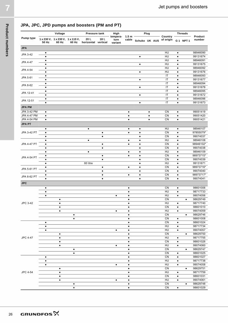
JPA, JPC, JPD pumps and boosters (PM and PT)
Pump type
Voltage Pressure tank High tempera-
ture variant
1.5 m cable
PlugCountry of origin
ThreadsProduct number1 x 230 V,
50 Hz1 x 230 V,
60 Hz1 x 115 V,
60 Hz20 l,
horizontal18 l,
verticalSchuko UK AUS G 1 NPT 1
JPA
JPA 3-42● HU ● 98946090
● ● HU ● 99131674
JPA 4-47● HU ● 98946091
● ● HU ● 99131675
JPA 4-54● HU ● 98946092
● ● HU ● 99131676
JPA 5-61● IT ● 98946093
● ● IT ● 99131677
JPA 8-62● IT ● 98946094
● ● IT ● 99131678
JPA 12-41● IT ● 98946095
● ● IT ● 99131672
JPA 12-51● IT ● 98946096
● ● IT ● 99131673
JPA PM
JPA 3-42 PM ● ● ● CN ● 99051419
JPA 4-47 PM ● ● ● CN ● 99051420
JPA 4-54 PM ● ● ● CN ● 99051421
JPA PT
JPA 3-42 PT
● ● ● ● HU ● 98946107
● ● ● ● CN ● 97855079*
● ● ● CN ● 99074037
JPA 4-47 PT
● ● ● ● HU ● 98946108
● ● ● ● CN ● 98946102*
● ● ● CN ● 99074038
JPA 4-54 PT
● ● ● ● HU ● 98946109
● ● ● ● CN ● 98973715*
● ● ● CN ● 99074039
● 60 litre ● HU ● 99131671
JPA 5-61 PT● ● ● ● CN ● 98973716*
● ● ● CN ● 99074040
JPA 8-62 PT● ● ● ● CN ● 98973717*
● ● ● CN ● 99074041
JPC
JPC 3-42
● ● CN ● 98601006
● ● HU ● 98717733
● ● ● HU ● 99074056
● ● CN ● 98629749
● ● HU ● 98717740
● ● CN ● 98601010
● ● ● HU ● 99074059
● ● CN ● 98629746
● ● CN ● 98601008
JPC 4-47
● ● CN ● 98601024
● ● HU ● 98717734
● ● ● HU ● 99074057
● ● CN ● 98629750
● ● HU ● 98717755
● ● CN ● 98601026
● ● ● HU ● 99074060
● ● CN ● 98629747
● ● CN ● 98601025
JPC 4-54
● ● CN ● 98601027
● ● HU ● 98717738
● ● ● HU ● 99074058
● ● CN ● 98629751
● ● HU ● 98717759
● ● CN ● 98601031
● ● ● HU ● 99074061
● ● CN ● 98629748
● ● CN ● 98601029

Pro
du
ct
nu
mb
ers
Jet pumps and boosters 7
* SNI (Indonesia).
Ejector for JPD PT
JPC 5-48
● CN ● 99126394
● CN ● 99126399
● CN ● 99126401
JPC PM
JPC 3-42 PM● ● ● CN ● 99051419
● ● CN ● 98388472
JPC 4-47 PM● ● ● CN ● 99051420
● ● CN ● 98388473
JPC 4-54 PM● ● ● CN ● 99051421
● ● CN ● 98388475
JPC PT
JPC 3-42 PT
● ● ● CN ● 98616018
● ● ● CN ● 98616052
● ● ● CN ● 98629755
● ● ● CN ● 98616017
● ● ● CN ● 98629752
JPC 4-47 PT
● ● ● CN ● 98616054
● ● ● CN ● 98616055
● ● ● CN ● 98629756
● ● ● CN ● 98616053
● ● ● CN ● 98629753
JPC 4-54 PT
● ● ● CN ● 98616057
● ● ● CN ● 98616058
● ● ● CN ● 98629757
● ● ● CN ● 98616056
● ● ● CN ● 98629754
JPD PT
JPD 4-47 PT● ● ● ● CN ● 98973718*
● ● ● ● CN ● 99074042
JPD 4-54 PT● ● ● ● CN ● 98973719*
● ● ● ● CN ● 99074053
JPD 5-61 PT● ● ● ● CN ● 98973720*
● ● ● ● CN ● 99074054
JPD 8-62 PT● ● ● ● CN ● 98973721*
● ● ● ● CN ● 99074055
Pump type
Voltage Pressure tank High tempera-
ture variant
1.5 m cable
PlugCountry of origin
ThreadsProduct number1 x 230 V,
50 Hz1 x 230 V,
60 Hz1 x 115 V,
60 Hz20 l,
horizontal18 l,
verticalSchuko UK AUS G 1 NPT 1
Type Product number
E 20 96150012
E 25 96150013
E 30 96150014
27

Ac
ce
ss
orie
s
28
Jet pumps and boosters8
8. Accessories
The vital components of the booster solutions are also available as separate products. They can be combined with any pump to create a booster system.
Grundfos Pressure ManagerGrundfos PM 1 and PM 2 Pressure Managers are designed for automatic start/stop control of Grundfos pumps and other water supply pumps.
PM 1The PM 1 is suitable for applications where start/stop of the pump according to consumption is needed. It is the basic control solution offering start at 1.5 or 2.2 bar.
The PM 1 starts the pump when the start pressure is reached, and the pump keeps running as long as there is flow.
The PM 1 offers dry-running protection and cycling alarm for increased safety.
Fig. 34 PM 1
PM 2The PM 2 is the all-round control solution offering adjustable start at 1.5 to 5 bar. This enables customisation to different types of installations and ensures a high level of comfort.
The start pressure is set by means of DIP switches located behind the control panel, and the current pressure is indicated on the LED display on the front of the PM 2.
The PM 2 starts the pump when the start pressure is reached, and the pump keeps running as long as there is flow.
The PM 2 can be optimised for operation with an external pressure tank by enabling the 1 bar differential-pressure function. This function significantly reduces the number of operating hours of the pump in installations with a pressure tank.
Fig. 35 PM 2
FeaturesThe table below shows the features of PM 1 and PM 2. The main features are described after the table.
TM
05
50
89
32
12
TM
05
50
90
32
12
Feature PM 1 PM 2
Power-on indication ● ●
Pump running indication ● ●
Alarm indication ● ●
Dry-running protection ● ●
Free position in installation ● ●
Suitable for generator supply ● ●
Rotary outlet connection ● ●
Integrated non-return valve ● ●
Cycling alarm ● ●
Integrated pressure sensor from Grundfos Direct Sensors
●
Adjustable start pressure ●
Start/stop with 1 bar differential pressure ●
Automatic restarting after dry running ●
Maximum continuous operating time of 30 minutes ●
Pressure indication ●
Internal pressure tank ● ●
Ac
ce
ss
ori
es
Jet pumps and boosters 8
Anticycling
If there is a minor leakage in the system, or a tap has not been entirely closed, the PM 1 and PM 2 would normally start and stop the pump periodically. However, in order to avoid cycling, the anticycling function stops the pump and indicate an alarm.
Dry-running protection
The PM 1 and PM 2 incorporate dry-running protection that automatically stops the pump in case of dry running. The dry-running protection functions differently during priming and operation.
Adjustable start pressure (PM 2 only)
The booster can be set to start automatically within an adjustable pressure range of 1.5 to 5 bar. The current pressure is indicated on the LED display on the front of the PM 2.
Maximum continuous operating time (PM 2 only)
When this function is enabled, the pump stops when it has been running continuously for 30 minutes. The purpose of the function is to avoid unnecessary water and current consumption, e.g. in case of pipe fracture or considerable leakages.
Note: For further information, download the data booklet for Grundfos Pressure Manager using the following link or the QR code: http://net.grundfos.com/qr/i/97506325.
Grundfos pressure tanksGrundfos GT pressure tanks are long-life tanks, which are ideally suited for controlling the pressure in domestic as well as industrial applications.
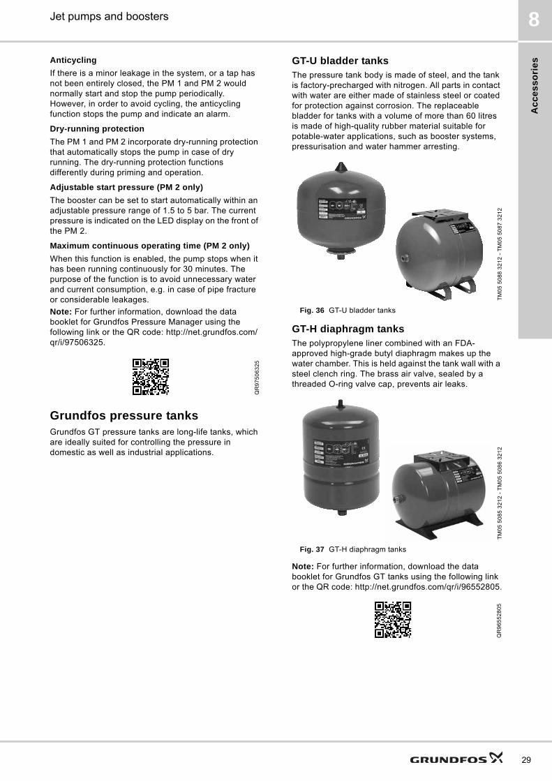
GT-U bladder tanksThe pressure tank body is made of steel, and the tank is factory-precharged with nitrogen. All parts in contact with water are either made of stainless steel or coated for protection against corrosion. The replaceable bladder for tanks with a volume of more than 60 litres is made of high-quality rubber material suitable for potable-water applications, such as booster systems, pressurisation and water hammer arresting.
Fig. 36 GT-U bladder tanks
GT-H diaphragm tanksThe polypropylene liner combined with an FDA-approved high-grade butyl diaphragm makes up the water chamber. This is held against the tank wall with a steel clench ring. The brass air valve, sealed by a threaded O-ring valve cap, prevents air leaks.
Fig. 37 GT-H diaphragm tanks
Note: For further information, download the data booklet for Grundfos GT tanks using the following link or the QR code: http://net.grundfos.com/qr/i/96552805.
QR
97
50
63
25
TM
05
50
88
32
12
- T
M0
5 5
08
7 3
21
2T
M0
5 5
08
5 3
21
2 -
TM
05
50
86
32
12
QR
96
55
28
05
29

Gru
nd
fos
Pro
du
ct C
en
ter
30
Jet pumps and boosters9
9. Grundfos Product Center
Subject to alterations.
All the information you need in one place Downloads
Performance curves, technical specifications, pictures, dimensional drawings, motor curves, wiring diagrams, spare parts, service kits, 3D drawings, documents, system parts. The Product Center displays any recent and saved items - including complete projects - right on the main page.
On the product pages, you can download installation and operating instructions, data booklets, service instructions, etc. in PDF format.
"SIZING" enables you to size a pump based on entered data and selection choices.
Online search and sizing tool to help you make the right choice.
http://product-selection.grundfos.com
"REPLACEMENT" enables you to find a replacement product.Search results will include information on the following
• the lowest purchase price• the lowest energy consumption• the lowest total life cycle cost.
"CATALOGUE" gives you access to the Grundfos product catalogue.
"LIQUIDS" enables you to find pumps designed for aggressive, flammable or other special liquids.

31

GRUNDFOS A/S DK-8850 Bjerringbro . DenmarkTelephone: +45 87 50 14 00www.grundfos.com
V7112680 1116
ECM: 1197437 Th
e n
am
e G
run
dfo
s, t
he
Gru
nd
fos
log
o,
an
d b
e t
hin
k i
nn
ov
ate
are
re
gis
tere
d t
rad
em
ark
s o
wn
ed
by
Gru
nd
fos
Ho
ldin
g A
/S o
r G
run
dfo
s A
/S,
De
nm
ark
. A
ll ri
gh
ts r
ese
rve
d w
orl
dw
ide
.©
Co
pyr
igh
t G
run
dfo
s H
old
ing
A/S