Embed Size (px)
Citation preview

1 Article Jet Electric Generator 7 3 14 after Joseph
Jet Electric Generator
Alexander Bolonkin Department of Electrical Engineering and Telecommunication Technology CUNY New YorkUSA CampR USA abolonkinjunocom
Abstract Author offers and develops the theory of a new simple cheap efficient electric (electron) generator This generator can convert pressure or kinetic energy of any non-conductive flow (gas liquid) into direct current (DC) The generator can convert the mechanical energy of any engine into high voltage DC One can covert the wind and water energy into electricity without turbine One can convert the rest energy of an internal combustion engine or turbojet engine in electricity and increase its efficiency ----------------------------------------------------------------------- Key words Jet Electric Generator Electron generator AB generator Wind electric generator Water electric generator DC generator High voltage generator
Introduction
Electric Generator
In electricity generation an electric generator is a device that converts mechanical energy to electrical
energy A generator forces electric current to flow through an external circuit The source of
mechanical energy may be a reciprocating or turbine steam engine water falling through a turbine or
waterwheel an internal combustion engine a wind turbine a hand crank compressed air or any other
source of mechanical energy Generators provide nearly all of the power for electric power grids
The reverse conversion of electrical energy into mechanical energy is done by an electric motor and
motors and generators have many similarities Many motors can be mechanically driven to generate
electricity and frequently make acceptable generators
The MHD (magneto hydrodynamic) generator transforms thermal energy and kinetic energy
directly into electricity MHD generators are different from traditional electric generators in that they
operate at high temperatures without moving parts MHD was developed because the hot exhaust gas
of an MHD generator can heat the boilers of a steam power plant increasing overall efficiency MHD
was developed as a topping cycle to increase the efficiency of electric generation especially when
burning coal or natural gas MHD dynamos are the complement of MHD propulsors which have been
applied to pump liquid metals and in several experimental ship engines
An MHD generator like a conventional generator relies on moving a conductor through a magnetic
field to generate electric current The MHD generator uses hot conductive plasma as the moving
conductor The mechanical dynamo in contrast uses the motion of mechanical devices to accomplish
this MHD generators are technically practical for fossil fuels but have been overtaken by other less
expensive technologies such as combined cycles in which a gas turbines or molten carbonate fuel
cells exhaust heats steam to power a steam turbine
Natural MHD dynamos are an active area of research in plasma physics and are of great interest to the
geophysics and astrophysics communities since the magnetic fields of the earth and sun are produced
by these natural dynamos
2
The jet electric generator offered in given article is principal different from MHD generator One does
not need hot plasma magnets and a magnetic field itrsquos easier cheaper by ten times and more
efficient It might serve for purposes of propulsion MHD is also not reversible
The first author publications about new jet AB electron-electric generator are in [1] ndash [5]
AB Jet Electric Generator (ABJEG) Principal schema Jet electric generator (ABJEG) is very simple (fig2) That is nonconductive tube 2 injector 4 of electrons (ions) in beginning of tube and collector 5 of electrons (ions) in end of tube If generator does not have grounding 10 one may have the charge compensator 10 The electron injector is conventional cold field electron emission (edge needles) or hot electron emission (hot cathode) See more detailed description and computation of the injectors in next chapters Correct design of them practically does not consume electricity The charge (electron) collector may be conductive plates or conductive net located in end of tube The ABJEG needs in it if one does not have the good grounding or want to improve the efficiency The charge compensator deletes the opposed charges (electrons and positive ions) and injects the surplus charges into exhaust flow The charge compensator is necessary if ABJEG cannot have the grounding (for example ABJEG is located in aircraft) The offered generator can work on non-conductive gas or liquid It may be convertible to either a pump or propulsion system
Fig2 Schema of AB Jet electric generator a ndash side view b ndash back view Notations 1 is pressured gas or liquid 2 is Jet Electric Generator (ABJEG) 3 is flow 4 is injector of electrons 5 is collector of electrons 6 is source of injector voltage 7 is useful load 8 is compensator of the lost electrons 9 is compensator of internal charge 10 is grounding (if no grounding we need the compensator 8) 11 needles of the ejector 4 Work of the ABJEG (fig 3) The nonconductive pressure gas (or liquid) locates into volume 1 (fig2) Under pressure the gas flow into ABJEG (fig3 tube 1) In beginning of tube the injector 2 injects into gas the electrons 5 The electrons are captured by the flow 6 and move to end of tube 1 against the electric
3 field between injector and collector They brake the flow (get the work create the opposed pressure) The flow reaches the collector (plate 7 11) and charges it When the charge of collector became over the charge of the injector 4 (fig2) the electrical current appears in the circuit It consume by load 7 (fig2)
Fig3 Work of the AB Jet Electric Generator Notations 1 is Jet Electric Generator 2 is needle injector 3 is opposed cathode plate of needle injector 4 is the electric intensity lines of needle injector 5 is the injected electrons 6 is flow of working mass (gas or liquid) 7 is plate of collector 8 is the electric intensity lines of the needle injector 9 is electron moved against the electric field under flow pressure 10 is electron not captured collector 11 conductive isolated surface of collector 12 is conductive coating of the dielectric tube 1 for balancing the internal charge of electrons 13 is collector of electrons 14 are conductive internal plates of collector Different designs of the injectors collectors compensators and electric schemas of ABJEG are possible One of them is shown in fig 4 This injector has a conductivity net a high transparency and collector having opposed charged plates This collector attracts the electron and increases the efficiency Correct design of them practically does not consume electricity
Fig4 Electric schema of one version of the ABJEG Notations 2 is electron injector 4 is useful load 5 is compensator 6 is exhaust flow 7 is input stream 8 is trajectory of electrons 9 is control 10 is anode net of injector 11 is collector with opposed charged plates
Differences of ABJEG (AB Electric Generator) relative to MHD (magnetohydrodynamic
generator) The jet electric generator is principal different from MHD generator MHD works on plasma or conductive
liquid ABJEG works on dielectric (non-conductive gas or liquid (for example water)) MHD needs in very hot
gas (high conductivity plasma) The currently available materials cannot endure this temperature Result in
practical systems is low efficiency Converting of gas to a high conductivity plasma requests a lot of energy for
heating ionization and dissociation of gas Most part of this energy is useless loses The MHD needs very
powerful magnets (better superconductive magnets) For increasing efficiency the MHD connects to
conventional gas turbine The installation is very complex and expensive MHD is not reversible
4 Advantages of ABJEG over MHD
1 ABJEG does not need hot plasma magnets and magnetic field
2 ABJEG is easier cheaper by ten (perhaps a hundred) times and more efficient
3 ABJEG may be used for getting energy from wind river and moving water (ocean stream)
4 ABJEG can be small and it may be used for getting energy in small vehicles
5 ABJEG can work as propulsion or pump
Advantages ABJEG over the conventional electric (magnetic) generator 1 ABJEG is easier by some times than a conventional generator
2 ABJEG produces high voltage electricity Big electric stations do not need a heavy expensive and
vulnerable transformer
3 ABJEG produces a direct current (DC) That is suitable for transfer over long distance
4 The small DC generators can easy connect to the common net Not necessary the harmonize the
frequency and phase of current
Theory of Jet Electric generator Computation and Estimation 1 Ion and electron speed Ion mobility The ion speed onto the gas (air) jet may be computed by equation js = qn-b-E + qD-(dn-dx) (1) where js is density of electric current about jet Am2 q = 16times10-19 C is charge of single electron C n- is density of injected negative charges in 1 m3 b - is charge mobility of negative charges m2sV E is electric intensity Vm D- is diffusion coefficient of charges dn-dx is gradient of charges For our estimation we put dn-dx = 0 In this case js = qn-b-E Q = qn v = bE js = Qv (2) where Q is density of the negative charge in 1 m3 v is speed of the negative charges about jet ms The air negative charge mobility for normal pressure and temperature T = 20oC is In dry air b- = 19times10-4 m2sV in humid air b- = 21times10-4 m2sV (3) In Table 1 is given the ions mobility of different gases for pressure 700 mm Hg and for T = 18oC Table 1 Ions mobility of different gases for pressure 700 mm Hg and for T = 18 oC
Gas Ion mobility 10-4 m2sV b+ b-
Gas Ion mobility 10-4 m2sV b+ b-
Gas Ion mobility 10-4 m2sV b+ b-
Hydrogen 591 826 Nitrogen 127 182 Chloride 065 051 Oxygen 129 181 CO2 110 114
Source [8] p357
In diapason of pressure from 13 to 6times106 Pa the mobility follows the Law bp = const where p is air pressure When air density decreases the charge mobility increases The mobility strength depends upon the purity of gas The ion gas mobility may be recalculated in other gas pressure p and temperature T by equation
0
00
pT
pTbb (4)
where lower index ldquoordquo mean the initial (known) point At the Earth surface H = 0 km T0 = 288 K p = 1 atm at
altitude H = 10 km T0 = 223 K p = 0261 atm For normal air density the electric intensity must be less than 3 MV (E lt 3 MVm) and depends from pressure Electron mobility The ratio Ep asymp constant Conductivity σ of gas depends upon density of charges particles n and their mobility b for example
5
1 nneb (5)
where b is mobility of the electron λ is a free path of electron Electron mobility depends from ratio En This ratio is given in Table 2 Table 2 Electron mobility be in gas vs En
Gas En times10-17 003 Vcm2
En times10-17 1 Vcm2
En times10-17 100 Vcm2
Gas En times10-17 003 Vcm2
En times10-17 1 Vcm2
En times10-17 100 Vcm2
N2 13600 670 370 He 8700 930 1030 O2 32000 1150 590 Ne 16000 1400 960 CO2 670 780 480 Ar 14800 410 270 H2 5700 700 470 Xe 1980 - 240
Source Physics Encyclopedia httpwwwfemtocomuaarticlespart_22926html The electrons may connect to the neutral molecules and produce the negative ions (for example affinity of electron to O2 equals 03 - 087 eV to H2O equals 09 eV [7] p424) That way the computation of the mobility of a gas containing electrons and ions is a complex problem Usually the computations are made for all electrons converted to ions The maximal electric intensity in air at the Earth surface is Em = 3 MVm If atmospheric pressure changes the Em also changes by law Emp = constant Example 4 If E = 105 Vm than v = 20 ms in Earth surface conditions 2 Electron injectors There are some methods for getting the electron emissions hot cathode emission cold field electron emission (edge cold emission edge cathode) The photo emission radiation emission radioisotope emission and so on usually produce the positive and negative ions together We consider only the hot emission and the cold field electron emission (edge cathodes) which produces only electrons Hot electron emission Current i of diode from potential (voltage) U is
23CUi (6)
where C is constant which depends from form and size cathode For plate diode
103322
9
42
6
20d
S
m
e
d
SC
e
(7)
where εo = 88510-12 Fm S is area of cathode (equals area of anode) cm2 d is distance between cathode and anode cm eme is the ratio of the electron charge to electron mass Ckg Result of computation equation (7) is in fig 5
0 200 400 600 800 1000 1200 1400 1600 1800 2000
0
01
02
03
04
05
06
07
Voltage V
Den
sity
of c
urre
ncy
Ac
m
2
Current density Acm2 1d2=05 1 15 2 25
CC-F1a
1d2=05
1d2=10
1d2=15
1d2=2
1d2=25
6 Fig5 Electric current via voltage the plain cathodes for different ratio of the distance The maximal hot cathode emission computed by equation js = BT2exp(-AkT) (8) where B is coefficient Acm2K2 T is cathode temperature K k = 138times10-23 [JK] is Bolzmann constant A = eφ is thermoelectron exit work J φ is the exit work (output energy of electron) in eV e = 1610 -19 Both values A B depend from material of cathode and its cover The ldquoArdquo changes from 13 to 5 eV the ldquoBrdquo changes from 05 to120 Acm2K2 Boron thermo-cathode produces electric current up 200 Acm2 For temperature 1400 -1500K the cathode can produce current up 1000 Acm2 The life of cathode can reach some years Exit energy from metal are (eV) W 45 Mo 43 Fe 43 Na 22 eV (9) From cathode covered by optimal layer(s) the exit work is in Table 3 Table 3 Exit work (eV) from cathode is covered by the optimal layer(s) Cr ndash Cs
Ti ndash Cs
Ni ndash Cs
Mo ndash Cs
W ndash Ba
Pt - Cs
W - O ndash K
Steel- Cs
Mo2C-Cs
WSi2-Cs
171
132
137
154
175
138
176
152
145
147
Source [8] Kikoin Table of physic values 1976 p 445 (in Russian)
Results of computation the maximal electric current (in vacuum) via cathode temperature for the
different exit work of electrons f are presented in fig6
Fig6 The maximal electric current via cathode temperature for the different exit work of electrons f Method of producing electrons and positive ions is well developed in the ionic thrusters for space apparatus The field electron emission (The edge cold emission) The cold field electron emission uses the edge cathodes It is known that the electric intensity Ee in the edge (needle) is Ee = Ua (10) Here a is radios of the edge If voltage between the edge and nears net (anode) is U = 1000 V the radius of edge a = 10-5 m electric intensity at edge is the Ee = 108 Vm That is enough for the electron emission The density of electric current may reach up 104 Acm2 For getting the required current we make the need number of edges
7 The density of electric current approximately is computed by equation
)10822394(
26 23721
101041 EEj (11)
where j is density of electric current Acm2 E is electric intensity near edge Vcm φ is exit work (output energy of electron field electron emission) eV The density of current is computed by equation (11) in Table 4 below
Φ = 20 eV Etimes10-7 lg j
φ = 45 eV Etimes10-7 lg j
φ = 63 eV Etimes10-7 lg j
10 298 20 -333 20 -129
12 445 30 157 40 -088
14 5 49 40 406 60 325
16 627 50 559 80 534
18 689 60 662 100 666
20 740 70 736 120 752
22 782 80 794 140 816
24 816 90 839 160 865
26 845 100 876 180 904
120 932 200 936
Source httpwwwfemtocomuaarticlespart_10034html
Example Assume we have needle with edge S1 = 10-4
cm2 φ = 2 eV and net S2 = 10times10 = 10
2 cm
2
located at distance L = 10 cm The local voltage between the needle and net is U = 102 volts Than
electric intensity at edge of needle current density and the electric current is
A101010Acm10Vcm101010
1010 43
1
237
14
22
1
2 jSijLS
USE (12)
Here j is taken from Table 4 or computed by equation (11) If we need in the electric current 10 A we
must locate 100 needles in the entrance area 1times1 m of generator
Computation of equation (11) is presented in fig 7
0 1 2 3 4 5 6 7
x 107
10-20
10-15
10-10
10-5
100
105
1010
Electric intencity Vcm
De
ns
ity o
f C
urr
en
cy
A
cm
2
Current density Acm2 f=15 2 25 3 35 4 45
CC3-F1
f = 45
f = 40
f = 35
f = 30
f = 25
f = 20
f = 1 5
Fig7 Density of electric current the noodle injector via the electric intensity for different the field electron
emissions f
3 Internal and outer pressure on the generator surface The electric charges located in the ABJEG generator produce electric intensity and internal and outer pressure The electric intensity can create electrical breakdown the pressure can destroy the generator
8 a) For the cylindrical generator the electric intensity and pressure may be estimated by equations
2
EpV
i
rkE
a
(13)
where E is electric intensify Vm k = 9109 is electric constant Nm2C2 τ is the linear charge Cm ε is dielectric constant for given material (ε = 1 - 1000) r is radius of tube (generator) m i is electric current A Va is average speed of flow inside of generator ms p is pressure Nm2 σ is the density of charge Cm2 at an tube surface Example Assume the generator has r = 01 m Va = 50 ms i = 01 A Let us take as isolator GE Lexan having the dielectric strength Em = 640 MVm and ε = 3 Than from (13) we have E = 120 MVm lt Em = 640 MVm If E gt Em we can locate the part of the compensate charge inside generator b) For plate of generator having rectangular entrance htimesw = 1times 3 m and compensation charges on two sides the electric intensity and pressure may be estimated by equations
22
4 2
0EpwV
ikE
a
(14)
where w is width of entrance m ε is dielectric coefficient of the isolator
4 Loss of energy and matter to ionization Let us estimate the energy and matter requested for ionization and discharge in the offered ABJEG
generator Assume we have ABJEG generator having the power P = 10000 kW and a work voltage V
= 1 MV In this case the electric current is i = PV = 10 A = 10 Cs
Assume we use the nitrogen N2 for ionization (a very bad gas for it) It has exit work about 5 eV and
relative molecular weight 14 One molecule (ion) of N2 weights mN = 1416710-27
= 234 10-26
kg
The 1 ampere has nA = 1e = 11610-19
= 6251018
ionss Consumption of the ion mass is
M = mNi nA = 234 10-26
10 6251018
= 14610-6
kgs = 14610-6
3610-3
= 52610-3
kghour asymp 5
gramhour
If electron exit work equals φ = 45 eV the power spent extraction of one electron is E1 = φe =
451610-19
= 7210-19
J
The total power for the electron extraction is E = inAE1 = 106251018
7210-19
= 45 W
The received values mass M and power E are very small in comparison with conventional
consumption of fuel (tons in hour) and generator power (thousands of kW)
Important note (Compensation of flow charge) Any contact collector cannot collect ALL charges
Part of them will fly away That means the generator (apparatus) will be charged positive (if fly away
electrons or negative ions) or negative (if fly away the positive ions) It is easy to delete the negative
charges by edge The large positive charge we may delete by a small ion accelerator The art of ion
engines for vacuum is well developed They may be used as injectors and dischargers in the first
design
The charges may be deleted also by grounding
Below is spark gap in air Table 5 Electric spark in air (in mm For normal atmospheric pressure)
Voltage kV Two edges Two spheres d = 5 sm Two plates
20 155 58 61
40 455 13 137
100 200 15 367
Two spheres d = 2 sm
200 410 262 753
300 600 530 114
9 Source [6] p124
Application of Jet Electric Generator
1 Electric Station
Estimations of main parameters of ABJEG for an electric station
Assume we have ABJEG as the cylindrical tube with constant cross-section area f = 001 m2 (fig8)
Let us take the pressure in balloon 1 p = 05 atm = 50000 Nm2 and the gas (air) speed in exit of
ABJEG V = 50 ms
Fig8 Principal schema of the Jet Electric Generator Nominations 1 ndash balloon with pressure gas 2 ndash jet electric generator (ABJEG) 3 ndash injector of electrons 4 ndash collector of electrons 5 ndash outer load 6 ndash gas flow 7 ndash
grounding
The useful (working) pressure equals the pressure p into balloon 1 minus the kinetic loss of a gas in the exit
2
42
42
1 1084742
502251105
2 m
NVpp (15)
That is anti-pressure of electron (ions) moving against the flow Power of ABJEG is
kW22450108474010 4
1VpfP (16)
Coefficient of efficiency of ABJEG
9705
84741
p
p (17)
Let us estimate the voltage and current for length L = 03 m of active part of tube The maximum of electric intensity Em must be less than
m
V
b
VEm
5
41052
102
50 (18)
Let us take the electric intensity E = 2105 Vm Than the work voltage will be
U = EL=210503 = 60 kV (19)
The current will be
i = PU = 24260 = 04 A (20)
The ABJEG is suitable as simple (tube) additional electric generator for internal combustion engines
working by Ottorsquos cycle or any machine having pressure or high speed exhaust gases That increases
10
their efficiency Vast industrial possibilities are opened by recovery of otherwise waste energies at low
opportunity cost
The under critical speed w and consumption m of ideal gases from the converging nozzle may be
estimated by equations
k
kk
k
k
p
p
p
p
v
p
k
kfm
p
pvp
k
kw
1
1
2
2
1
2
1
1
1
1
211
121
12 (21)
where k is adiabatic coefficient in gas dynamic p is gas pressure in beginning ldquo1rdquo and end ldquo2rdquo of nozzle
v is specific gas volume f is cross-section area of tube m2
Critical ratio βk and critical speed wk is
11
1
21
1 121
1
2vp
k
kw
p
p
kp
pkk
k
k
kk (22)
For one atom gas k = 166 and βk = 042
For two atom gas k = 14 and βk = 0528
For one atom gas k = 13 and βk = 0546
Equation of gas state and continuity equation is
constv
wfmRTpV (23)
Here V is gas volume m3 m is gas mass kg T is gas temperature K R is gas constant for air R =
287 Jkg K
These equations allow to compute the data of gas flow
The steam is very suitable gas for converting its extension directly to electricity without steam piston
machines steam turbines and magnetic generator directly to electricity by ABJEG
The steam speed after a converting nozzle may be computed by equation
217244 iiw (24)
where I is the steam enthalpy in the beginning and end of the adiabatic process The enthalpy is found
in diagram ldquoisrdquo by data of the beginning and end of the adiabatic process
2 Wind Energy
The simplest wind electric generator (ABJEG) is shown in fig9 In end of mast 1 is installed the
electron injector 2 The wind 6 pick up the electrons and moves them to the Earth surface Under Earth
surface the electros throw the grounding 4 and outer electric load 3 return to injector 2
11
Fig9 Simplest wind generator Notations 1 ndash mast 2 - electron injector 3 ndash electric load 4 ndash grounding 5 ndash
trajectories of electrons 6 = wind
The electric resistance of the grounding may be estimated by equation
aR
2 (25)
ρ is specific average resistance of the ground m a is average radius the plate of grounding
The good grounding must be in place of underground water or in sea water For sea water ρ asymp 02 m
For underground water ρ is below Connection having one line underground widely uses in
communication
Suggested method may be used for getting the wind energy at high altitude The injector must be
supported at high altitude by balloon dirigible or wing apparatus [1]
a) Power of a wind energy N [Watt Joulesec]
N = 05 AV3 [W] (26)
The coefficient of efficiency equals about 02 -025 for EABG 015 - 035 for low speed
propeller rotors (ratio of blade tip speed to wind speed equals 1) = 045 - 05 for high speed
propeller rotors ( = 5 - 7) The Darrieus rotor has = 035 - 04 The gyroplane rotor has 01 - 015
The air balloon and the drag (parachute) rotor has = 015 - 02 The Makani rotor has 015 - 025
The theoretical maximum equals asymp 06 Theoretical maximum of the electron generator is 025 A -
front (forward) area of the electron injector rotor air balloon or parachute [m2] - density of air o
=1225 kgm3 for air at sea level altitude H = 0 = 0736 at altitude H = 5 km = 0413 at H = 10
km V is average annually wind speed ms
Table 5 Relative density ρr and temperature of the standard atmosphere via altitude
H km 0 04 1 2 3 6 8 10 12
ρr=ρρo 1 0954 0887 0784 0692 0466 0352 0261 0191
T K 288 287 282 276 269 250 237 223 217
Source [6]
The salient point here is that the strength of wind power depends upon the wind speed (by third order) If the wind speed increases by two times the power increases by 8 times If the wind speed increases 3 times the wind power increases 27 times The wind speed increases in altitude and can reach in constant air stream at altitude H = 5 ndash 7 km up V = 30 ndash 40 ms At altitude the wind is more stableconstant which is one of the major advantages that an airborne wind systems has over ground wind systems For comparison of different wind systems of the engineers must make computations for average annual wind speed V0 = 6 ms (or 10 ms) and altitude H0 = 10 m For standard wind speed and altitude the maximal wind power equals 66 Wm2 The energy E produced in one year is (1 year 302 106 work sec) [J]
E = 3600 24 350N 30 106N [J] (27)
3 Water Energy
Typical hydroelectric station is shown in fig 10 The water from a top level 1 flows by tube 2 to ABJEG 3 and after working runoff to lower level 4
12
Fig 10 Typical Hydroelectric station with ABJEG Notations 1 - upper source 2 - water canal 3 ndash ABJEG 4 ndash lower runoff
Note It is possible also the water electric generator shown in fig 8 One may be used in rivers and ocean streams
1 Power of a water flow is N [Watt Joulesec]
N = ηρBgH [W] (28)
The coefficient of efficiency equals about 08 - 095 - density of liquid asymp 1000 kgm3 for
water B is the flow in cubic meters per second g = 981 ms2 is Earth gravity H is the height
difference between inlet and outlet of installation m (fig10)
Without ABJEG the H and V connected by equation
H = V22g (29)
2 Resistance of water Salt water conducts an electric current The specific electric resistance of water is significantly depends from salinity of water When we have the plates (nets) with both sides (cathode and anode) the specific electric resistance are 1 Distilled water R asymp 106 Ωm 2 Fresh water R = 40 - 200 Ωm (depends from water salinity) (30) 3 Sea water R asymp 02 Ωm In our case in one side we have the electron injector (cathode) which has conventionally a small area In this case the specific electric resistance is Ro = R 4π a (31) where a is radius of needle (or cathode) m this radius conventionally is very small (mm) That means the Ro has an electric resistance of hundreds Ohms We can neglect their influence in the installation efficiency 3 Electron speed in water The charge mobility in water is Cl- is 0667times10-7 m2sV Na+ is 0450 times10-7 m2sV (32) As you see the mobility of ions in water is very small The applied voltage in water is also small That means the ion speed v is small in the comparison with water speed In many case we can put v = bE asymp 0 If v gt 0 the electrons accelerate the water (E gt 0 and installation spends energy works as engine) If v lt 0 the electrons brake the water (E lt 0 and the correct installation can produce energy works as electric generator) If v = 0 (electron speed about installation equals water speed V) the electric resistance is zero 4 The efficiency of installation from back electric current may be estimated by equation η asymp 1(1+ RuRo) (33) where Ru is an useful electric resistance Ratio RuRo conventionally is small and η is closed to 1 5 Specific power of Installation N1 [Wm2] The specific power of the offered installation may be estimated by a series of equations N1 asymp η A1t = ηQ1ELt = ηQ1EV = jsU = ηρB1gh =05ηm1V2 (34) where A1 is energy of flow through 1 m2 Jm2 t is time sec B1 is flow in m3 through cross section area of flow 1 m2 E is electric intensity Vm L is distance between injector and net (cathode and anode) V is
13 flow speed ms js is density of electric current Am2 U is electric voltage V m1 is flow mass per second through area 1 m2 Q1 is density of the negative charge in 1 m3 g = 981 ms
2 is Earth gravity h is the height
difference between inlet and outlet of installation (between electron injector and net between cathode and
anode) m
Summary
Relatively no progress has been made in electric generators in the last years The author proposes a fundamentally new efficient electric generator for gas and liquid No gas
(water) turbine no dynamo-machine Practically there is only a tube
It is not comparable to conventional MHD generator or heat machine The MHD generator requests
very high temperature which cannot be endured by available materials MHD generator is very
complex and expensive
Author offers and develops theory of a new simple cheap and efficient electric (electron) generator
This generator can convert pressure or kinetic energy of the any non-conductive flow (gas liquid) into
direct current (DC) The generator can convert the mechanical energy of any engine in high voltage
DC One can covert in electricity the wind and water energy without turbine One can convert the rest
energy of an internal combustion engine or turbojet engine in electricity and increase its efficiency
ABJEG may be propulsors which have been applied to pump a gas or dielectric liquid and as engine in
several experimental ships
As any new idea the suggested concept is in need of research and development The theoretical
problems do not require fundamental breakthroughs It is necessary to design small cheap installations
to study and get an experience in the design electron wind (water) generator
This paper has suggested some design solutions from patent application The author has many
detailed analysis in addition to these presented projects Organizations or investors are interested in
these projects can address the author (httpBolonkinnarodru aBolonkinjunocom
abolonkingmailcom)
The closed ideas are in [1]-[5] Researches and information related to this topic are presented in [6]-
[9]
ACKNOWLEDGEMENT
The author wishes to acknowledge Joseph Friedlander for correcting the English and offering useful
advice and suggestions
References [1] Bolonkin AA Electronic Wind Generator
Electrical and Power Engineering Frontier Sep 2013 Vol 2 Iss 3 PP 64-71
httpwwwacademicpuborgepefIssueaspxVolume=2ampNumber=3ampAbstr=false httpviXraorgabs13060046 wwwIntellectualArchivecom httpsarchiveorgdetailsArticleElectronWindGenerator6613AsterShmuelWithPicture
httpwwwscribdcomdoc146177073Electronic-Wind-Generator
[2] Bolonkin AA Electron Hydro Electric Generator International Journal of Advanced Engineering
Applications ISSN 2321-7723 (Online) Special Issue I 2013 httpfragrancejournalscompage_id=18 httpviXraorgabs13060196
httpwwwscribdcomdoc149489902Electron-Hydro-Electric-Generator 1089
httparchiveorgdetailsElectronHydroElectricGenerator_532 httpintellectualarchivecom
[3] Bolonkin AA Electron Super Speed Hydro Propulsion International Journal of Advanced Engineering
Applications Special Issue 1 pp15-19 (2013) httpviXraorgabs13060195
httpwwwscribdcomdoc149490731Electron-Super-Speed-Hydro-Propulsion
httparchiveorgdetailsElectronSuperSpeedHydroPropulsion
httpintellectualarchivecom 1090
14 httpfragrancejournalscomwp-contentuploads201303Special-Issue-1-4pdf
[4] Bolonkin AA Electron Air Hypersonic Propulsion International Journal of Advanced Engineering
Applications Vol1 Iss 6 pp42-47 (2012) httpviXraorgabs13060003
httpwwwscribdcomdoc145165015Electron-Air-Hypersonic-Propulsion
httpwwwscribdcomdoc146179116Electronic-Air-Hypersonic-Propulsion
httpfragrancejournalscomwp-contentuploads201303IJAEA-1-6-6pdf
[5] Bolonkin AA Electric Hypersonic Space Aircraft Global Science Journal 2 July 2014 httpviXraorgabs14070011 httpwwwscribdcomdoc232209230
httpintellectualarchivecom Ref 1288 [6] NI Koshkin and MG Shirkebich Directory of Elementary Physics Nauka Moscow 1982 (in Russian)
[7] IK Kikoin Table of Physics values Atomisdat Moscow 1976 (in Russian)
[8] SG Kalashnikov Electricity Moscow Nauka 1985(in Russian)
[9] Wikipedia Electric Generator httpwikipediaorg
May 27 2014
Alexander Bolonkin Alexander A Bolonkin was born in the former Soviet Union He holds a doctoral degree in aviation
engineering from Moscow Aviation Institute and post-doctoral degree in aerospace engineering from Leningrad
Polytechnic University He has held the positions of senior engineering at the Antonov Aircraft Design
Company and chairman of the Reliability Department at the Glushko Rocket design Company He has also
lectured at the Moscow Aviation Universities Following his arrival in the United States in 1988 he lectured at
the New Jersey Institute of Technology and worked as a senior researcher at NASA and the US Air Force
Research Laboratories
Professor AA Bolonkin is the author of more than 200 scientific articles and books and has 17 inventions to
his credit His most notable books include Non-Rocket Space Launch and Flight (Elsevier 2006)
httpviXraorgabs14070174 New Concepts Ideas and Innovations in Aerospace Technology and Human
Life (NOVA 2008) httpviXraorgabs13090193 Human Immortality and Electronic Civilization (Lulu
1994) Femtotechnologies and Revolutionary Projects Lambert Academic Publishing Germany 2011 538 p
httpviXraorgabs13090191 Life and Science Lambert 2011 205 pgs httpviXraorgabs13090205 Author WEB httpBolonkinnarodru

2
The jet electric generator offered in given article is principal different from MHD generator One does
not need hot plasma magnets and a magnetic field itrsquos easier cheaper by ten times and more
efficient It might serve for purposes of propulsion MHD is also not reversible
The first author publications about new jet AB electron-electric generator are in [1] ndash [5]
AB Jet Electric Generator (ABJEG) Principal schema Jet electric generator (ABJEG) is very simple (fig2) That is nonconductive tube 2 injector 4 of electrons (ions) in beginning of tube and collector 5 of electrons (ions) in end of tube If generator does not have grounding 10 one may have the charge compensator 10 The electron injector is conventional cold field electron emission (edge needles) or hot electron emission (hot cathode) See more detailed description and computation of the injectors in next chapters Correct design of them practically does not consume electricity The charge (electron) collector may be conductive plates or conductive net located in end of tube The ABJEG needs in it if one does not have the good grounding or want to improve the efficiency The charge compensator deletes the opposed charges (electrons and positive ions) and injects the surplus charges into exhaust flow The charge compensator is necessary if ABJEG cannot have the grounding (for example ABJEG is located in aircraft) The offered generator can work on non-conductive gas or liquid It may be convertible to either a pump or propulsion system
Fig2 Schema of AB Jet electric generator a ndash side view b ndash back view Notations 1 is pressured gas or liquid 2 is Jet Electric Generator (ABJEG) 3 is flow 4 is injector of electrons 5 is collector of electrons 6 is source of injector voltage 7 is useful load 8 is compensator of the lost electrons 9 is compensator of internal charge 10 is grounding (if no grounding we need the compensator 8) 11 needles of the ejector 4 Work of the ABJEG (fig 3) The nonconductive pressure gas (or liquid) locates into volume 1 (fig2) Under pressure the gas flow into ABJEG (fig3 tube 1) In beginning of tube the injector 2 injects into gas the electrons 5 The electrons are captured by the flow 6 and move to end of tube 1 against the electric
3 field between injector and collector They brake the flow (get the work create the opposed pressure) The flow reaches the collector (plate 7 11) and charges it When the charge of collector became over the charge of the injector 4 (fig2) the electrical current appears in the circuit It consume by load 7 (fig2)
Fig3 Work of the AB Jet Electric Generator Notations 1 is Jet Electric Generator 2 is needle injector 3 is opposed cathode plate of needle injector 4 is the electric intensity lines of needle injector 5 is the injected electrons 6 is flow of working mass (gas or liquid) 7 is plate of collector 8 is the electric intensity lines of the needle injector 9 is electron moved against the electric field under flow pressure 10 is electron not captured collector 11 conductive isolated surface of collector 12 is conductive coating of the dielectric tube 1 for balancing the internal charge of electrons 13 is collector of electrons 14 are conductive internal plates of collector Different designs of the injectors collectors compensators and electric schemas of ABJEG are possible One of them is shown in fig 4 This injector has a conductivity net a high transparency and collector having opposed charged plates This collector attracts the electron and increases the efficiency Correct design of them practically does not consume electricity
Fig4 Electric schema of one version of the ABJEG Notations 2 is electron injector 4 is useful load 5 is compensator 6 is exhaust flow 7 is input stream 8 is trajectory of electrons 9 is control 10 is anode net of injector 11 is collector with opposed charged plates
Differences of ABJEG (AB Electric Generator) relative to MHD (magnetohydrodynamic
generator) The jet electric generator is principal different from MHD generator MHD works on plasma or conductive
liquid ABJEG works on dielectric (non-conductive gas or liquid (for example water)) MHD needs in very hot
gas (high conductivity plasma) The currently available materials cannot endure this temperature Result in
practical systems is low efficiency Converting of gas to a high conductivity plasma requests a lot of energy for
heating ionization and dissociation of gas Most part of this energy is useless loses The MHD needs very
powerful magnets (better superconductive magnets) For increasing efficiency the MHD connects to
conventional gas turbine The installation is very complex and expensive MHD is not reversible
4 Advantages of ABJEG over MHD
1 ABJEG does not need hot plasma magnets and magnetic field
2 ABJEG is easier cheaper by ten (perhaps a hundred) times and more efficient
3 ABJEG may be used for getting energy from wind river and moving water (ocean stream)
4 ABJEG can be small and it may be used for getting energy in small vehicles
5 ABJEG can work as propulsion or pump
Advantages ABJEG over the conventional electric (magnetic) generator 1 ABJEG is easier by some times than a conventional generator
2 ABJEG produces high voltage electricity Big electric stations do not need a heavy expensive and
vulnerable transformer
3 ABJEG produces a direct current (DC) That is suitable for transfer over long distance
4 The small DC generators can easy connect to the common net Not necessary the harmonize the
frequency and phase of current
Theory of Jet Electric generator Computation and Estimation 1 Ion and electron speed Ion mobility The ion speed onto the gas (air) jet may be computed by equation js = qn-b-E + qD-(dn-dx) (1) where js is density of electric current about jet Am2 q = 16times10-19 C is charge of single electron C n- is density of injected negative charges in 1 m3 b - is charge mobility of negative charges m2sV E is electric intensity Vm D- is diffusion coefficient of charges dn-dx is gradient of charges For our estimation we put dn-dx = 0 In this case js = qn-b-E Q = qn v = bE js = Qv (2) where Q is density of the negative charge in 1 m3 v is speed of the negative charges about jet ms The air negative charge mobility for normal pressure and temperature T = 20oC is In dry air b- = 19times10-4 m2sV in humid air b- = 21times10-4 m2sV (3) In Table 1 is given the ions mobility of different gases for pressure 700 mm Hg and for T = 18oC Table 1 Ions mobility of different gases for pressure 700 mm Hg and for T = 18 oC
Gas Ion mobility 10-4 m2sV b+ b-
Gas Ion mobility 10-4 m2sV b+ b-
Gas Ion mobility 10-4 m2sV b+ b-
Hydrogen 591 826 Nitrogen 127 182 Chloride 065 051 Oxygen 129 181 CO2 110 114
Source [8] p357
In diapason of pressure from 13 to 6times106 Pa the mobility follows the Law bp = const where p is air pressure When air density decreases the charge mobility increases The mobility strength depends upon the purity of gas The ion gas mobility may be recalculated in other gas pressure p and temperature T by equation
0
00
pT
pTbb (4)
where lower index ldquoordquo mean the initial (known) point At the Earth surface H = 0 km T0 = 288 K p = 1 atm at
altitude H = 10 km T0 = 223 K p = 0261 atm For normal air density the electric intensity must be less than 3 MV (E lt 3 MVm) and depends from pressure Electron mobility The ratio Ep asymp constant Conductivity σ of gas depends upon density of charges particles n and their mobility b for example
5
1 nneb (5)
where b is mobility of the electron λ is a free path of electron Electron mobility depends from ratio En This ratio is given in Table 2 Table 2 Electron mobility be in gas vs En
Gas En times10-17 003 Vcm2
En times10-17 1 Vcm2
En times10-17 100 Vcm2
Gas En times10-17 003 Vcm2
En times10-17 1 Vcm2
En times10-17 100 Vcm2
N2 13600 670 370 He 8700 930 1030 O2 32000 1150 590 Ne 16000 1400 960 CO2 670 780 480 Ar 14800 410 270 H2 5700 700 470 Xe 1980 - 240
Source Physics Encyclopedia httpwwwfemtocomuaarticlespart_22926html The electrons may connect to the neutral molecules and produce the negative ions (for example affinity of electron to O2 equals 03 - 087 eV to H2O equals 09 eV [7] p424) That way the computation of the mobility of a gas containing electrons and ions is a complex problem Usually the computations are made for all electrons converted to ions The maximal electric intensity in air at the Earth surface is Em = 3 MVm If atmospheric pressure changes the Em also changes by law Emp = constant Example 4 If E = 105 Vm than v = 20 ms in Earth surface conditions 2 Electron injectors There are some methods for getting the electron emissions hot cathode emission cold field electron emission (edge cold emission edge cathode) The photo emission radiation emission radioisotope emission and so on usually produce the positive and negative ions together We consider only the hot emission and the cold field electron emission (edge cathodes) which produces only electrons Hot electron emission Current i of diode from potential (voltage) U is
23CUi (6)
where C is constant which depends from form and size cathode For plate diode
103322
9
42
6
20d
S
m
e
d
SC
e
(7)
where εo = 88510-12 Fm S is area of cathode (equals area of anode) cm2 d is distance between cathode and anode cm eme is the ratio of the electron charge to electron mass Ckg Result of computation equation (7) is in fig 5
0 200 400 600 800 1000 1200 1400 1600 1800 2000
0
01
02
03
04
05
06
07
Voltage V
Den
sity
of c
urre
ncy
Ac
m
2
Current density Acm2 1d2=05 1 15 2 25
CC-F1a
1d2=05
1d2=10
1d2=15
1d2=2
1d2=25
6 Fig5 Electric current via voltage the plain cathodes for different ratio of the distance The maximal hot cathode emission computed by equation js = BT2exp(-AkT) (8) where B is coefficient Acm2K2 T is cathode temperature K k = 138times10-23 [JK] is Bolzmann constant A = eφ is thermoelectron exit work J φ is the exit work (output energy of electron) in eV e = 1610 -19 Both values A B depend from material of cathode and its cover The ldquoArdquo changes from 13 to 5 eV the ldquoBrdquo changes from 05 to120 Acm2K2 Boron thermo-cathode produces electric current up 200 Acm2 For temperature 1400 -1500K the cathode can produce current up 1000 Acm2 The life of cathode can reach some years Exit energy from metal are (eV) W 45 Mo 43 Fe 43 Na 22 eV (9) From cathode covered by optimal layer(s) the exit work is in Table 3 Table 3 Exit work (eV) from cathode is covered by the optimal layer(s) Cr ndash Cs
Ti ndash Cs
Ni ndash Cs
Mo ndash Cs
W ndash Ba
Pt - Cs
W - O ndash K
Steel- Cs
Mo2C-Cs
WSi2-Cs
171
132
137
154
175
138
176
152
145
147
Source [8] Kikoin Table of physic values 1976 p 445 (in Russian)
Results of computation the maximal electric current (in vacuum) via cathode temperature for the
different exit work of electrons f are presented in fig6
Fig6 The maximal electric current via cathode temperature for the different exit work of electrons f Method of producing electrons and positive ions is well developed in the ionic thrusters for space apparatus The field electron emission (The edge cold emission) The cold field electron emission uses the edge cathodes It is known that the electric intensity Ee in the edge (needle) is Ee = Ua (10) Here a is radios of the edge If voltage between the edge and nears net (anode) is U = 1000 V the radius of edge a = 10-5 m electric intensity at edge is the Ee = 108 Vm That is enough for the electron emission The density of electric current may reach up 104 Acm2 For getting the required current we make the need number of edges
7 The density of electric current approximately is computed by equation
)10822394(
26 23721
101041 EEj (11)
where j is density of electric current Acm2 E is electric intensity near edge Vcm φ is exit work (output energy of electron field electron emission) eV The density of current is computed by equation (11) in Table 4 below
Φ = 20 eV Etimes10-7 lg j
φ = 45 eV Etimes10-7 lg j
φ = 63 eV Etimes10-7 lg j
10 298 20 -333 20 -129
12 445 30 157 40 -088
14 5 49 40 406 60 325
16 627 50 559 80 534
18 689 60 662 100 666
20 740 70 736 120 752
22 782 80 794 140 816
24 816 90 839 160 865
26 845 100 876 180 904
120 932 200 936
Source httpwwwfemtocomuaarticlespart_10034html
Example Assume we have needle with edge S1 = 10-4
cm2 φ = 2 eV and net S2 = 10times10 = 10
2 cm
2
located at distance L = 10 cm The local voltage between the needle and net is U = 102 volts Than
electric intensity at edge of needle current density and the electric current is
A101010Acm10Vcm101010
1010 43
1
237
14
22
1
2 jSijLS
USE (12)
Here j is taken from Table 4 or computed by equation (11) If we need in the electric current 10 A we
must locate 100 needles in the entrance area 1times1 m of generator
Computation of equation (11) is presented in fig 7
0 1 2 3 4 5 6 7
x 107
10-20
10-15
10-10
10-5
100
105
1010
Electric intencity Vcm
De
ns
ity o
f C
urr
en
cy
A
cm
2
Current density Acm2 f=15 2 25 3 35 4 45
CC3-F1
f = 45
f = 40
f = 35
f = 30
f = 25
f = 20
f = 1 5
Fig7 Density of electric current the noodle injector via the electric intensity for different the field electron
emissions f
3 Internal and outer pressure on the generator surface The electric charges located in the ABJEG generator produce electric intensity and internal and outer pressure The electric intensity can create electrical breakdown the pressure can destroy the generator
8 a) For the cylindrical generator the electric intensity and pressure may be estimated by equations
2
EpV
i
rkE
a
(13)
where E is electric intensify Vm k = 9109 is electric constant Nm2C2 τ is the linear charge Cm ε is dielectric constant for given material (ε = 1 - 1000) r is radius of tube (generator) m i is electric current A Va is average speed of flow inside of generator ms p is pressure Nm2 σ is the density of charge Cm2 at an tube surface Example Assume the generator has r = 01 m Va = 50 ms i = 01 A Let us take as isolator GE Lexan having the dielectric strength Em = 640 MVm and ε = 3 Than from (13) we have E = 120 MVm lt Em = 640 MVm If E gt Em we can locate the part of the compensate charge inside generator b) For plate of generator having rectangular entrance htimesw = 1times 3 m and compensation charges on two sides the electric intensity and pressure may be estimated by equations
22
4 2
0EpwV
ikE
a
(14)
where w is width of entrance m ε is dielectric coefficient of the isolator
4 Loss of energy and matter to ionization Let us estimate the energy and matter requested for ionization and discharge in the offered ABJEG
generator Assume we have ABJEG generator having the power P = 10000 kW and a work voltage V
= 1 MV In this case the electric current is i = PV = 10 A = 10 Cs
Assume we use the nitrogen N2 for ionization (a very bad gas for it) It has exit work about 5 eV and
relative molecular weight 14 One molecule (ion) of N2 weights mN = 1416710-27
= 234 10-26
kg
The 1 ampere has nA = 1e = 11610-19
= 6251018
ionss Consumption of the ion mass is
M = mNi nA = 234 10-26
10 6251018
= 14610-6
kgs = 14610-6
3610-3
= 52610-3
kghour asymp 5
gramhour
If electron exit work equals φ = 45 eV the power spent extraction of one electron is E1 = φe =
451610-19
= 7210-19
J
The total power for the electron extraction is E = inAE1 = 106251018
7210-19
= 45 W
The received values mass M and power E are very small in comparison with conventional
consumption of fuel (tons in hour) and generator power (thousands of kW)
Important note (Compensation of flow charge) Any contact collector cannot collect ALL charges
Part of them will fly away That means the generator (apparatus) will be charged positive (if fly away
electrons or negative ions) or negative (if fly away the positive ions) It is easy to delete the negative
charges by edge The large positive charge we may delete by a small ion accelerator The art of ion
engines for vacuum is well developed They may be used as injectors and dischargers in the first
design
The charges may be deleted also by grounding
Below is spark gap in air Table 5 Electric spark in air (in mm For normal atmospheric pressure)
Voltage kV Two edges Two spheres d = 5 sm Two plates
20 155 58 61
40 455 13 137
100 200 15 367
Two spheres d = 2 sm
200 410 262 753
300 600 530 114
9 Source [6] p124
Application of Jet Electric Generator
1 Electric Station
Estimations of main parameters of ABJEG for an electric station
Assume we have ABJEG as the cylindrical tube with constant cross-section area f = 001 m2 (fig8)
Let us take the pressure in balloon 1 p = 05 atm = 50000 Nm2 and the gas (air) speed in exit of
ABJEG V = 50 ms
Fig8 Principal schema of the Jet Electric Generator Nominations 1 ndash balloon with pressure gas 2 ndash jet electric generator (ABJEG) 3 ndash injector of electrons 4 ndash collector of electrons 5 ndash outer load 6 ndash gas flow 7 ndash
grounding
The useful (working) pressure equals the pressure p into balloon 1 minus the kinetic loss of a gas in the exit
2
42
42
1 1084742
502251105
2 m
NVpp (15)
That is anti-pressure of electron (ions) moving against the flow Power of ABJEG is
kW22450108474010 4
1VpfP (16)
Coefficient of efficiency of ABJEG
9705
84741
p
p (17)
Let us estimate the voltage and current for length L = 03 m of active part of tube The maximum of electric intensity Em must be less than
m
V
b
VEm
5
41052
102
50 (18)
Let us take the electric intensity E = 2105 Vm Than the work voltage will be
U = EL=210503 = 60 kV (19)
The current will be
i = PU = 24260 = 04 A (20)
The ABJEG is suitable as simple (tube) additional electric generator for internal combustion engines
working by Ottorsquos cycle or any machine having pressure or high speed exhaust gases That increases
10
their efficiency Vast industrial possibilities are opened by recovery of otherwise waste energies at low
opportunity cost
The under critical speed w and consumption m of ideal gases from the converging nozzle may be
estimated by equations
k
kk
k
k
p
p
p
p
v
p
k
kfm
p
pvp
k
kw
1
1
2
2
1
2
1
1
1
1
211
121
12 (21)
where k is adiabatic coefficient in gas dynamic p is gas pressure in beginning ldquo1rdquo and end ldquo2rdquo of nozzle
v is specific gas volume f is cross-section area of tube m2
Critical ratio βk and critical speed wk is
11
1
21
1 121
1
2vp
k
kw
p
p
kp
pkk
k
k
kk (22)
For one atom gas k = 166 and βk = 042
For two atom gas k = 14 and βk = 0528
For one atom gas k = 13 and βk = 0546
Equation of gas state and continuity equation is
constv
wfmRTpV (23)
Here V is gas volume m3 m is gas mass kg T is gas temperature K R is gas constant for air R =
287 Jkg K
These equations allow to compute the data of gas flow
The steam is very suitable gas for converting its extension directly to electricity without steam piston
machines steam turbines and magnetic generator directly to electricity by ABJEG
The steam speed after a converting nozzle may be computed by equation
217244 iiw (24)
where I is the steam enthalpy in the beginning and end of the adiabatic process The enthalpy is found
in diagram ldquoisrdquo by data of the beginning and end of the adiabatic process
2 Wind Energy
The simplest wind electric generator (ABJEG) is shown in fig9 In end of mast 1 is installed the
electron injector 2 The wind 6 pick up the electrons and moves them to the Earth surface Under Earth
surface the electros throw the grounding 4 and outer electric load 3 return to injector 2
11
Fig9 Simplest wind generator Notations 1 ndash mast 2 - electron injector 3 ndash electric load 4 ndash grounding 5 ndash
trajectories of electrons 6 = wind
The electric resistance of the grounding may be estimated by equation
aR
2 (25)
ρ is specific average resistance of the ground m a is average radius the plate of grounding
The good grounding must be in place of underground water or in sea water For sea water ρ asymp 02 m
For underground water ρ is below Connection having one line underground widely uses in
communication
Suggested method may be used for getting the wind energy at high altitude The injector must be
supported at high altitude by balloon dirigible or wing apparatus [1]
a) Power of a wind energy N [Watt Joulesec]
N = 05 AV3 [W] (26)
The coefficient of efficiency equals about 02 -025 for EABG 015 - 035 for low speed
propeller rotors (ratio of blade tip speed to wind speed equals 1) = 045 - 05 for high speed
propeller rotors ( = 5 - 7) The Darrieus rotor has = 035 - 04 The gyroplane rotor has 01 - 015
The air balloon and the drag (parachute) rotor has = 015 - 02 The Makani rotor has 015 - 025
The theoretical maximum equals asymp 06 Theoretical maximum of the electron generator is 025 A -
front (forward) area of the electron injector rotor air balloon or parachute [m2] - density of air o
=1225 kgm3 for air at sea level altitude H = 0 = 0736 at altitude H = 5 km = 0413 at H = 10
km V is average annually wind speed ms
Table 5 Relative density ρr and temperature of the standard atmosphere via altitude
H km 0 04 1 2 3 6 8 10 12
ρr=ρρo 1 0954 0887 0784 0692 0466 0352 0261 0191
T K 288 287 282 276 269 250 237 223 217
Source [6]
The salient point here is that the strength of wind power depends upon the wind speed (by third order) If the wind speed increases by two times the power increases by 8 times If the wind speed increases 3 times the wind power increases 27 times The wind speed increases in altitude and can reach in constant air stream at altitude H = 5 ndash 7 km up V = 30 ndash 40 ms At altitude the wind is more stableconstant which is one of the major advantages that an airborne wind systems has over ground wind systems For comparison of different wind systems of the engineers must make computations for average annual wind speed V0 = 6 ms (or 10 ms) and altitude H0 = 10 m For standard wind speed and altitude the maximal wind power equals 66 Wm2 The energy E produced in one year is (1 year 302 106 work sec) [J]
E = 3600 24 350N 30 106N [J] (27)
3 Water Energy
Typical hydroelectric station is shown in fig 10 The water from a top level 1 flows by tube 2 to ABJEG 3 and after working runoff to lower level 4
12
Fig 10 Typical Hydroelectric station with ABJEG Notations 1 - upper source 2 - water canal 3 ndash ABJEG 4 ndash lower runoff
Note It is possible also the water electric generator shown in fig 8 One may be used in rivers and ocean streams
1 Power of a water flow is N [Watt Joulesec]
N = ηρBgH [W] (28)
The coefficient of efficiency equals about 08 - 095 - density of liquid asymp 1000 kgm3 for
water B is the flow in cubic meters per second g = 981 ms2 is Earth gravity H is the height
difference between inlet and outlet of installation m (fig10)
Without ABJEG the H and V connected by equation
H = V22g (29)
2 Resistance of water Salt water conducts an electric current The specific electric resistance of water is significantly depends from salinity of water When we have the plates (nets) with both sides (cathode and anode) the specific electric resistance are 1 Distilled water R asymp 106 Ωm 2 Fresh water R = 40 - 200 Ωm (depends from water salinity) (30) 3 Sea water R asymp 02 Ωm In our case in one side we have the electron injector (cathode) which has conventionally a small area In this case the specific electric resistance is Ro = R 4π a (31) where a is radius of needle (or cathode) m this radius conventionally is very small (mm) That means the Ro has an electric resistance of hundreds Ohms We can neglect their influence in the installation efficiency 3 Electron speed in water The charge mobility in water is Cl- is 0667times10-7 m2sV Na+ is 0450 times10-7 m2sV (32) As you see the mobility of ions in water is very small The applied voltage in water is also small That means the ion speed v is small in the comparison with water speed In many case we can put v = bE asymp 0 If v gt 0 the electrons accelerate the water (E gt 0 and installation spends energy works as engine) If v lt 0 the electrons brake the water (E lt 0 and the correct installation can produce energy works as electric generator) If v = 0 (electron speed about installation equals water speed V) the electric resistance is zero 4 The efficiency of installation from back electric current may be estimated by equation η asymp 1(1+ RuRo) (33) where Ru is an useful electric resistance Ratio RuRo conventionally is small and η is closed to 1 5 Specific power of Installation N1 [Wm2] The specific power of the offered installation may be estimated by a series of equations N1 asymp η A1t = ηQ1ELt = ηQ1EV = jsU = ηρB1gh =05ηm1V2 (34) where A1 is energy of flow through 1 m2 Jm2 t is time sec B1 is flow in m3 through cross section area of flow 1 m2 E is electric intensity Vm L is distance between injector and net (cathode and anode) V is
13 flow speed ms js is density of electric current Am2 U is electric voltage V m1 is flow mass per second through area 1 m2 Q1 is density of the negative charge in 1 m3 g = 981 ms
2 is Earth gravity h is the height
difference between inlet and outlet of installation (between electron injector and net between cathode and
anode) m
Summary
Relatively no progress has been made in electric generators in the last years The author proposes a fundamentally new efficient electric generator for gas and liquid No gas
(water) turbine no dynamo-machine Practically there is only a tube
It is not comparable to conventional MHD generator or heat machine The MHD generator requests
very high temperature which cannot be endured by available materials MHD generator is very
complex and expensive
Author offers and develops theory of a new simple cheap and efficient electric (electron) generator
This generator can convert pressure or kinetic energy of the any non-conductive flow (gas liquid) into
direct current (DC) The generator can convert the mechanical energy of any engine in high voltage
DC One can covert in electricity the wind and water energy without turbine One can convert the rest
energy of an internal combustion engine or turbojet engine in electricity and increase its efficiency
ABJEG may be propulsors which have been applied to pump a gas or dielectric liquid and as engine in
several experimental ships
As any new idea the suggested concept is in need of research and development The theoretical
problems do not require fundamental breakthroughs It is necessary to design small cheap installations
to study and get an experience in the design electron wind (water) generator
This paper has suggested some design solutions from patent application The author has many
detailed analysis in addition to these presented projects Organizations or investors are interested in
these projects can address the author (httpBolonkinnarodru aBolonkinjunocom
abolonkingmailcom)
The closed ideas are in [1]-[5] Researches and information related to this topic are presented in [6]-
[9]
ACKNOWLEDGEMENT
The author wishes to acknowledge Joseph Friedlander for correcting the English and offering useful
advice and suggestions
References [1] Bolonkin AA Electronic Wind Generator
Electrical and Power Engineering Frontier Sep 2013 Vol 2 Iss 3 PP 64-71
httpwwwacademicpuborgepefIssueaspxVolume=2ampNumber=3ampAbstr=false httpviXraorgabs13060046 wwwIntellectualArchivecom httpsarchiveorgdetailsArticleElectronWindGenerator6613AsterShmuelWithPicture
httpwwwscribdcomdoc146177073Electronic-Wind-Generator
[2] Bolonkin AA Electron Hydro Electric Generator International Journal of Advanced Engineering
Applications ISSN 2321-7723 (Online) Special Issue I 2013 httpfragrancejournalscompage_id=18 httpviXraorgabs13060196
httpwwwscribdcomdoc149489902Electron-Hydro-Electric-Generator 1089
httparchiveorgdetailsElectronHydroElectricGenerator_532 httpintellectualarchivecom
[3] Bolonkin AA Electron Super Speed Hydro Propulsion International Journal of Advanced Engineering
Applications Special Issue 1 pp15-19 (2013) httpviXraorgabs13060195
httpwwwscribdcomdoc149490731Electron-Super-Speed-Hydro-Propulsion
httparchiveorgdetailsElectronSuperSpeedHydroPropulsion
httpintellectualarchivecom 1090
14 httpfragrancejournalscomwp-contentuploads201303Special-Issue-1-4pdf
[4] Bolonkin AA Electron Air Hypersonic Propulsion International Journal of Advanced Engineering
Applications Vol1 Iss 6 pp42-47 (2012) httpviXraorgabs13060003
httpwwwscribdcomdoc145165015Electron-Air-Hypersonic-Propulsion
httpwwwscribdcomdoc146179116Electronic-Air-Hypersonic-Propulsion
httpfragrancejournalscomwp-contentuploads201303IJAEA-1-6-6pdf
[5] Bolonkin AA Electric Hypersonic Space Aircraft Global Science Journal 2 July 2014 httpviXraorgabs14070011 httpwwwscribdcomdoc232209230
httpintellectualarchivecom Ref 1288 [6] NI Koshkin and MG Shirkebich Directory of Elementary Physics Nauka Moscow 1982 (in Russian)
[7] IK Kikoin Table of Physics values Atomisdat Moscow 1976 (in Russian)
[8] SG Kalashnikov Electricity Moscow Nauka 1985(in Russian)
[9] Wikipedia Electric Generator httpwikipediaorg
May 27 2014
Alexander Bolonkin Alexander A Bolonkin was born in the former Soviet Union He holds a doctoral degree in aviation
engineering from Moscow Aviation Institute and post-doctoral degree in aerospace engineering from Leningrad
Polytechnic University He has held the positions of senior engineering at the Antonov Aircraft Design
Company and chairman of the Reliability Department at the Glushko Rocket design Company He has also
lectured at the Moscow Aviation Universities Following his arrival in the United States in 1988 he lectured at
the New Jersey Institute of Technology and worked as a senior researcher at NASA and the US Air Force
Research Laboratories
Professor AA Bolonkin is the author of more than 200 scientific articles and books and has 17 inventions to
his credit His most notable books include Non-Rocket Space Launch and Flight (Elsevier 2006)
httpviXraorgabs14070174 New Concepts Ideas and Innovations in Aerospace Technology and Human
Life (NOVA 2008) httpviXraorgabs13090193 Human Immortality and Electronic Civilization (Lulu
1994) Femtotechnologies and Revolutionary Projects Lambert Academic Publishing Germany 2011 538 p
httpviXraorgabs13090191 Life and Science Lambert 2011 205 pgs httpviXraorgabs13090205 Author WEB httpBolonkinnarodru
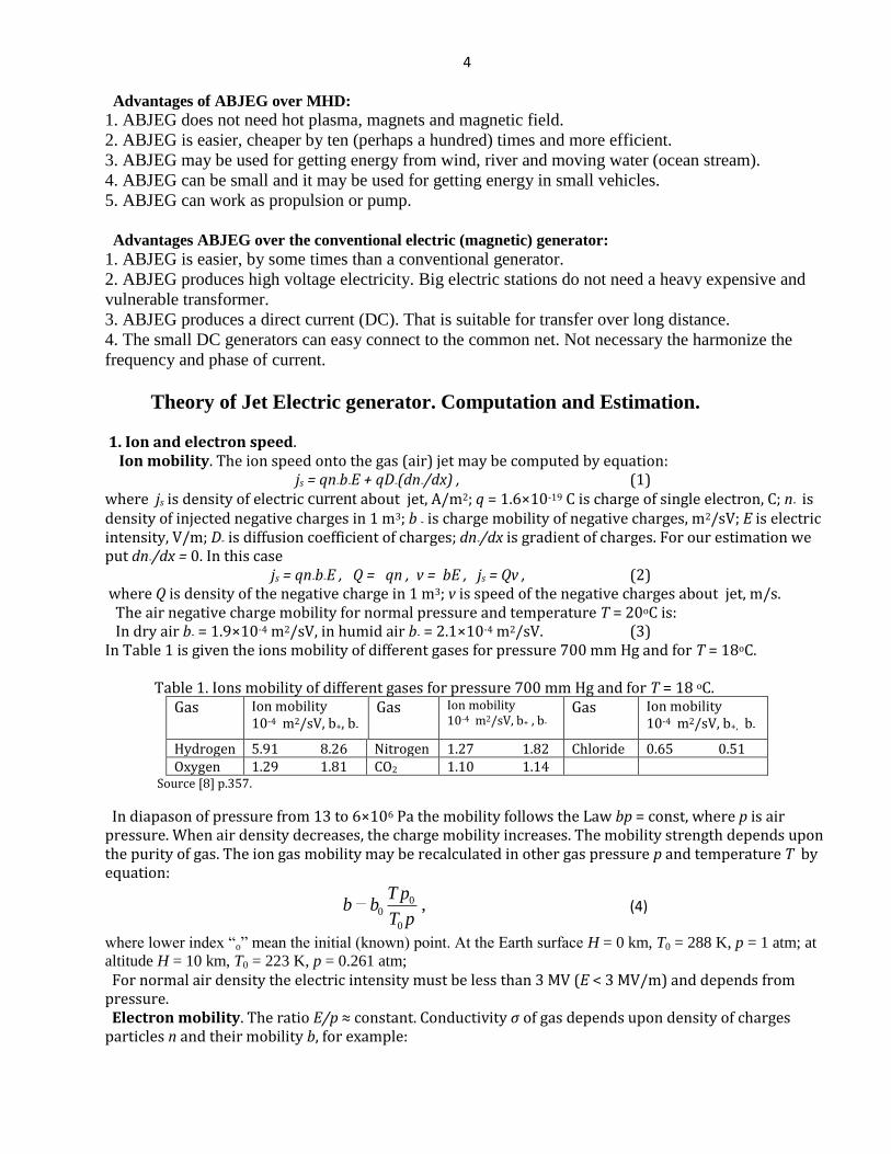

5
1 nneb (5)
where b is mobility of the electron λ is a free path of electron Electron mobility depends from ratio En This ratio is given in Table 2 Table 2 Electron mobility be in gas vs En
Gas En times10-17 003 Vcm2
En times10-17 1 Vcm2
En times10-17 100 Vcm2
Gas En times10-17 003 Vcm2
En times10-17 1 Vcm2
En times10-17 100 Vcm2
N2 13600 670 370 He 8700 930 1030 O2 32000 1150 590 Ne 16000 1400 960 CO2 670 780 480 Ar 14800 410 270 H2 5700 700 470 Xe 1980 - 240
Source Physics Encyclopedia httpwwwfemtocomuaarticlespart_22926html The electrons may connect to the neutral molecules and produce the negative ions (for example affinity of electron to O2 equals 03 - 087 eV to H2O equals 09 eV [7] p424) That way the computation of the mobility of a gas containing electrons and ions is a complex problem Usually the computations are made for all electrons converted to ions The maximal electric intensity in air at the Earth surface is Em = 3 MVm If atmospheric pressure changes the Em also changes by law Emp = constant Example 4 If E = 105 Vm than v = 20 ms in Earth surface conditions 2 Electron injectors There are some methods for getting the electron emissions hot cathode emission cold field electron emission (edge cold emission edge cathode) The photo emission radiation emission radioisotope emission and so on usually produce the positive and negative ions together We consider only the hot emission and the cold field electron emission (edge cathodes) which produces only electrons Hot electron emission Current i of diode from potential (voltage) U is
23CUi (6)
where C is constant which depends from form and size cathode For plate diode
103322
9
42
6
20d
S
m
e
d
SC
e
(7)
where εo = 88510-12 Fm S is area of cathode (equals area of anode) cm2 d is distance between cathode and anode cm eme is the ratio of the electron charge to electron mass Ckg Result of computation equation (7) is in fig 5
0 200 400 600 800 1000 1200 1400 1600 1800 2000
0
01
02
03
04
05
06
07
Voltage V
Den
sity
of c
urre
ncy
Ac
m
2
Current density Acm2 1d2=05 1 15 2 25
CC-F1a
1d2=05
1d2=10
1d2=15
1d2=2
1d2=25
6 Fig5 Electric current via voltage the plain cathodes for different ratio of the distance The maximal hot cathode emission computed by equation js = BT2exp(-AkT) (8) where B is coefficient Acm2K2 T is cathode temperature K k = 138times10-23 [JK] is Bolzmann constant A = eφ is thermoelectron exit work J φ is the exit work (output energy of electron) in eV e = 1610 -19 Both values A B depend from material of cathode and its cover The ldquoArdquo changes from 13 to 5 eV the ldquoBrdquo changes from 05 to120 Acm2K2 Boron thermo-cathode produces electric current up 200 Acm2 For temperature 1400 -1500K the cathode can produce current up 1000 Acm2 The life of cathode can reach some years Exit energy from metal are (eV) W 45 Mo 43 Fe 43 Na 22 eV (9) From cathode covered by optimal layer(s) the exit work is in Table 3 Table 3 Exit work (eV) from cathode is covered by the optimal layer(s) Cr ndash Cs
Ti ndash Cs
Ni ndash Cs
Mo ndash Cs
W ndash Ba
Pt - Cs
W - O ndash K
Steel- Cs
Mo2C-Cs
WSi2-Cs
171
132
137
154
175
138
176
152
145
147
Source [8] Kikoin Table of physic values 1976 p 445 (in Russian)
Results of computation the maximal electric current (in vacuum) via cathode temperature for the
different exit work of electrons f are presented in fig6
Fig6 The maximal electric current via cathode temperature for the different exit work of electrons f Method of producing electrons and positive ions is well developed in the ionic thrusters for space apparatus The field electron emission (The edge cold emission) The cold field electron emission uses the edge cathodes It is known that the electric intensity Ee in the edge (needle) is Ee = Ua (10) Here a is radios of the edge If voltage between the edge and nears net (anode) is U = 1000 V the radius of edge a = 10-5 m electric intensity at edge is the Ee = 108 Vm That is enough for the electron emission The density of electric current may reach up 104 Acm2 For getting the required current we make the need number of edges
7 The density of electric current approximately is computed by equation
)10822394(
26 23721
101041 EEj (11)
where j is density of electric current Acm2 E is electric intensity near edge Vcm φ is exit work (output energy of electron field electron emission) eV The density of current is computed by equation (11) in Table 4 below
Φ = 20 eV Etimes10-7 lg j
φ = 45 eV Etimes10-7 lg j
φ = 63 eV Etimes10-7 lg j
10 298 20 -333 20 -129
12 445 30 157 40 -088
14 5 49 40 406 60 325
16 627 50 559 80 534
18 689 60 662 100 666
20 740 70 736 120 752
22 782 80 794 140 816
24 816 90 839 160 865
26 845 100 876 180 904
120 932 200 936
Source httpwwwfemtocomuaarticlespart_10034html
Example Assume we have needle with edge S1 = 10-4
cm2 φ = 2 eV and net S2 = 10times10 = 10
2 cm
2
located at distance L = 10 cm The local voltage between the needle and net is U = 102 volts Than
electric intensity at edge of needle current density and the electric current is
A101010Acm10Vcm101010
1010 43
1
237
14
22
1
2 jSijLS
USE (12)
Here j is taken from Table 4 or computed by equation (11) If we need in the electric current 10 A we
must locate 100 needles in the entrance area 1times1 m of generator
Computation of equation (11) is presented in fig 7
0 1 2 3 4 5 6 7
x 107
10-20
10-15
10-10
10-5
100
105
1010
Electric intencity Vcm
De
ns
ity o
f C
urr
en
cy
A
cm
2
Current density Acm2 f=15 2 25 3 35 4 45
CC3-F1
f = 45
f = 40
f = 35
f = 30
f = 25
f = 20
f = 1 5
Fig7 Density of electric current the noodle injector via the electric intensity for different the field electron
emissions f
3 Internal and outer pressure on the generator surface The electric charges located in the ABJEG generator produce electric intensity and internal and outer pressure The electric intensity can create electrical breakdown the pressure can destroy the generator
8 a) For the cylindrical generator the electric intensity and pressure may be estimated by equations
2
EpV
i
rkE
a
(13)
where E is electric intensify Vm k = 9109 is electric constant Nm2C2 τ is the linear charge Cm ε is dielectric constant for given material (ε = 1 - 1000) r is radius of tube (generator) m i is electric current A Va is average speed of flow inside of generator ms p is pressure Nm2 σ is the density of charge Cm2 at an tube surface Example Assume the generator has r = 01 m Va = 50 ms i = 01 A Let us take as isolator GE Lexan having the dielectric strength Em = 640 MVm and ε = 3 Than from (13) we have E = 120 MVm lt Em = 640 MVm If E gt Em we can locate the part of the compensate charge inside generator b) For plate of generator having rectangular entrance htimesw = 1times 3 m and compensation charges on two sides the electric intensity and pressure may be estimated by equations
22
4 2
0EpwV
ikE
a
(14)
where w is width of entrance m ε is dielectric coefficient of the isolator
4 Loss of energy and matter to ionization Let us estimate the energy and matter requested for ionization and discharge in the offered ABJEG
generator Assume we have ABJEG generator having the power P = 10000 kW and a work voltage V
= 1 MV In this case the electric current is i = PV = 10 A = 10 Cs
Assume we use the nitrogen N2 for ionization (a very bad gas for it) It has exit work about 5 eV and
relative molecular weight 14 One molecule (ion) of N2 weights mN = 1416710-27
= 234 10-26
kg
The 1 ampere has nA = 1e = 11610-19
= 6251018
ionss Consumption of the ion mass is
M = mNi nA = 234 10-26
10 6251018
= 14610-6
kgs = 14610-6
3610-3
= 52610-3
kghour asymp 5
gramhour
If electron exit work equals φ = 45 eV the power spent extraction of one electron is E1 = φe =
451610-19
= 7210-19
J
The total power for the electron extraction is E = inAE1 = 106251018
7210-19
= 45 W
The received values mass M and power E are very small in comparison with conventional
consumption of fuel (tons in hour) and generator power (thousands of kW)
Important note (Compensation of flow charge) Any contact collector cannot collect ALL charges
Part of them will fly away That means the generator (apparatus) will be charged positive (if fly away
electrons or negative ions) or negative (if fly away the positive ions) It is easy to delete the negative
charges by edge The large positive charge we may delete by a small ion accelerator The art of ion
engines for vacuum is well developed They may be used as injectors and dischargers in the first
design
The charges may be deleted also by grounding
Below is spark gap in air Table 5 Electric spark in air (in mm For normal atmospheric pressure)
Voltage kV Two edges Two spheres d = 5 sm Two plates
20 155 58 61
40 455 13 137
100 200 15 367
Two spheres d = 2 sm
200 410 262 753
300 600 530 114
9 Source [6] p124
Application of Jet Electric Generator
1 Electric Station
Estimations of main parameters of ABJEG for an electric station
Assume we have ABJEG as the cylindrical tube with constant cross-section area f = 001 m2 (fig8)
Let us take the pressure in balloon 1 p = 05 atm = 50000 Nm2 and the gas (air) speed in exit of
ABJEG V = 50 ms
Fig8 Principal schema of the Jet Electric Generator Nominations 1 ndash balloon with pressure gas 2 ndash jet electric generator (ABJEG) 3 ndash injector of electrons 4 ndash collector of electrons 5 ndash outer load 6 ndash gas flow 7 ndash
grounding
The useful (working) pressure equals the pressure p into balloon 1 minus the kinetic loss of a gas in the exit
2
42
42
1 1084742
502251105
2 m
NVpp (15)
That is anti-pressure of electron (ions) moving against the flow Power of ABJEG is
kW22450108474010 4
1VpfP (16)
Coefficient of efficiency of ABJEG
9705
84741
p
p (17)
Let us estimate the voltage and current for length L = 03 m of active part of tube The maximum of electric intensity Em must be less than
m
V
b
VEm
5
41052
102
50 (18)
Let us take the electric intensity E = 2105 Vm Than the work voltage will be
U = EL=210503 = 60 kV (19)
The current will be
i = PU = 24260 = 04 A (20)
The ABJEG is suitable as simple (tube) additional electric generator for internal combustion engines
working by Ottorsquos cycle or any machine having pressure or high speed exhaust gases That increases
10
their efficiency Vast industrial possibilities are opened by recovery of otherwise waste energies at low
opportunity cost
The under critical speed w and consumption m of ideal gases from the converging nozzle may be
estimated by equations
k
kk
k
k
p
p
p
p
v
p
k
kfm
p
pvp
k
kw
1
1
2
2
1
2
1
1
1
1
211
121
12 (21)
where k is adiabatic coefficient in gas dynamic p is gas pressure in beginning ldquo1rdquo and end ldquo2rdquo of nozzle
v is specific gas volume f is cross-section area of tube m2
Critical ratio βk and critical speed wk is
11
1
21
1 121
1
2vp
k
kw
p
p
kp
pkk
k
k
kk (22)
For one atom gas k = 166 and βk = 042
For two atom gas k = 14 and βk = 0528
For one atom gas k = 13 and βk = 0546
Equation of gas state and continuity equation is
constv
wfmRTpV (23)
Here V is gas volume m3 m is gas mass kg T is gas temperature K R is gas constant for air R =
287 Jkg K
These equations allow to compute the data of gas flow
The steam is very suitable gas for converting its extension directly to electricity without steam piston
machines steam turbines and magnetic generator directly to electricity by ABJEG
The steam speed after a converting nozzle may be computed by equation
217244 iiw (24)
where I is the steam enthalpy in the beginning and end of the adiabatic process The enthalpy is found
in diagram ldquoisrdquo by data of the beginning and end of the adiabatic process
2 Wind Energy
The simplest wind electric generator (ABJEG) is shown in fig9 In end of mast 1 is installed the
electron injector 2 The wind 6 pick up the electrons and moves them to the Earth surface Under Earth
surface the electros throw the grounding 4 and outer electric load 3 return to injector 2
11
Fig9 Simplest wind generator Notations 1 ndash mast 2 - electron injector 3 ndash electric load 4 ndash grounding 5 ndash
trajectories of electrons 6 = wind
The electric resistance of the grounding may be estimated by equation
aR
2 (25)
ρ is specific average resistance of the ground m a is average radius the plate of grounding
The good grounding must be in place of underground water or in sea water For sea water ρ asymp 02 m
For underground water ρ is below Connection having one line underground widely uses in
communication
Suggested method may be used for getting the wind energy at high altitude The injector must be
supported at high altitude by balloon dirigible or wing apparatus [1]
a) Power of a wind energy N [Watt Joulesec]
N = 05 AV3 [W] (26)
The coefficient of efficiency equals about 02 -025 for EABG 015 - 035 for low speed
propeller rotors (ratio of blade tip speed to wind speed equals 1) = 045 - 05 for high speed
propeller rotors ( = 5 - 7) The Darrieus rotor has = 035 - 04 The gyroplane rotor has 01 - 015
The air balloon and the drag (parachute) rotor has = 015 - 02 The Makani rotor has 015 - 025
The theoretical maximum equals asymp 06 Theoretical maximum of the electron generator is 025 A -
front (forward) area of the electron injector rotor air balloon or parachute [m2] - density of air o
=1225 kgm3 for air at sea level altitude H = 0 = 0736 at altitude H = 5 km = 0413 at H = 10
km V is average annually wind speed ms
Table 5 Relative density ρr and temperature of the standard atmosphere via altitude
H km 0 04 1 2 3 6 8 10 12
ρr=ρρo 1 0954 0887 0784 0692 0466 0352 0261 0191
T K 288 287 282 276 269 250 237 223 217
Source [6]
The salient point here is that the strength of wind power depends upon the wind speed (by third order) If the wind speed increases by two times the power increases by 8 times If the wind speed increases 3 times the wind power increases 27 times The wind speed increases in altitude and can reach in constant air stream at altitude H = 5 ndash 7 km up V = 30 ndash 40 ms At altitude the wind is more stableconstant which is one of the major advantages that an airborne wind systems has over ground wind systems For comparison of different wind systems of the engineers must make computations for average annual wind speed V0 = 6 ms (or 10 ms) and altitude H0 = 10 m For standard wind speed and altitude the maximal wind power equals 66 Wm2 The energy E produced in one year is (1 year 302 106 work sec) [J]
E = 3600 24 350N 30 106N [J] (27)
3 Water Energy
Typical hydroelectric station is shown in fig 10 The water from a top level 1 flows by tube 2 to ABJEG 3 and after working runoff to lower level 4
12
Fig 10 Typical Hydroelectric station with ABJEG Notations 1 - upper source 2 - water canal 3 ndash ABJEG 4 ndash lower runoff
Note It is possible also the water electric generator shown in fig 8 One may be used in rivers and ocean streams
1 Power of a water flow is N [Watt Joulesec]
N = ηρBgH [W] (28)
The coefficient of efficiency equals about 08 - 095 - density of liquid asymp 1000 kgm3 for
water B is the flow in cubic meters per second g = 981 ms2 is Earth gravity H is the height
difference between inlet and outlet of installation m (fig10)
Without ABJEG the H and V connected by equation
H = V22g (29)
2 Resistance of water Salt water conducts an electric current The specific electric resistance of water is significantly depends from salinity of water When we have the plates (nets) with both sides (cathode and anode) the specific electric resistance are 1 Distilled water R asymp 106 Ωm 2 Fresh water R = 40 - 200 Ωm (depends from water salinity) (30) 3 Sea water R asymp 02 Ωm In our case in one side we have the electron injector (cathode) which has conventionally a small area In this case the specific electric resistance is Ro = R 4π a (31) where a is radius of needle (or cathode) m this radius conventionally is very small (mm) That means the Ro has an electric resistance of hundreds Ohms We can neglect their influence in the installation efficiency 3 Electron speed in water The charge mobility in water is Cl- is 0667times10-7 m2sV Na+ is 0450 times10-7 m2sV (32) As you see the mobility of ions in water is very small The applied voltage in water is also small That means the ion speed v is small in the comparison with water speed In many case we can put v = bE asymp 0 If v gt 0 the electrons accelerate the water (E gt 0 and installation spends energy works as engine) If v lt 0 the electrons brake the water (E lt 0 and the correct installation can produce energy works as electric generator) If v = 0 (electron speed about installation equals water speed V) the electric resistance is zero 4 The efficiency of installation from back electric current may be estimated by equation η asymp 1(1+ RuRo) (33) where Ru is an useful electric resistance Ratio RuRo conventionally is small and η is closed to 1 5 Specific power of Installation N1 [Wm2] The specific power of the offered installation may be estimated by a series of equations N1 asymp η A1t = ηQ1ELt = ηQ1EV = jsU = ηρB1gh =05ηm1V2 (34) where A1 is energy of flow through 1 m2 Jm2 t is time sec B1 is flow in m3 through cross section area of flow 1 m2 E is electric intensity Vm L is distance between injector and net (cathode and anode) V is
13 flow speed ms js is density of electric current Am2 U is electric voltage V m1 is flow mass per second through area 1 m2 Q1 is density of the negative charge in 1 m3 g = 981 ms
2 is Earth gravity h is the height
difference between inlet and outlet of installation (between electron injector and net between cathode and
anode) m
Summary
Relatively no progress has been made in electric generators in the last years The author proposes a fundamentally new efficient electric generator for gas and liquid No gas
(water) turbine no dynamo-machine Practically there is only a tube
It is not comparable to conventional MHD generator or heat machine The MHD generator requests
very high temperature which cannot be endured by available materials MHD generator is very
complex and expensive
Author offers and develops theory of a new simple cheap and efficient electric (electron) generator
This generator can convert pressure or kinetic energy of the any non-conductive flow (gas liquid) into
direct current (DC) The generator can convert the mechanical energy of any engine in high voltage
DC One can covert in electricity the wind and water energy without turbine One can convert the rest
energy of an internal combustion engine or turbojet engine in electricity and increase its efficiency
ABJEG may be propulsors which have been applied to pump a gas or dielectric liquid and as engine in
several experimental ships
As any new idea the suggested concept is in need of research and development The theoretical
problems do not require fundamental breakthroughs It is necessary to design small cheap installations
to study and get an experience in the design electron wind (water) generator
This paper has suggested some design solutions from patent application The author has many
detailed analysis in addition to these presented projects Organizations or investors are interested in
these projects can address the author (httpBolonkinnarodru aBolonkinjunocom
abolonkingmailcom)
The closed ideas are in [1]-[5] Researches and information related to this topic are presented in [6]-
[9]
ACKNOWLEDGEMENT
The author wishes to acknowledge Joseph Friedlander for correcting the English and offering useful
advice and suggestions
References [1] Bolonkin AA Electronic Wind Generator
Electrical and Power Engineering Frontier Sep 2013 Vol 2 Iss 3 PP 64-71
httpwwwacademicpuborgepefIssueaspxVolume=2ampNumber=3ampAbstr=false httpviXraorgabs13060046 wwwIntellectualArchivecom httpsarchiveorgdetailsArticleElectronWindGenerator6613AsterShmuelWithPicture
httpwwwscribdcomdoc146177073Electronic-Wind-Generator
[2] Bolonkin AA Electron Hydro Electric Generator International Journal of Advanced Engineering
Applications ISSN 2321-7723 (Online) Special Issue I 2013 httpfragrancejournalscompage_id=18 httpviXraorgabs13060196
httpwwwscribdcomdoc149489902Electron-Hydro-Electric-Generator 1089
httparchiveorgdetailsElectronHydroElectricGenerator_532 httpintellectualarchivecom
[3] Bolonkin AA Electron Super Speed Hydro Propulsion International Journal of Advanced Engineering
Applications Special Issue 1 pp15-19 (2013) httpviXraorgabs13060195
httpwwwscribdcomdoc149490731Electron-Super-Speed-Hydro-Propulsion
httparchiveorgdetailsElectronSuperSpeedHydroPropulsion
httpintellectualarchivecom 1090
14 httpfragrancejournalscomwp-contentuploads201303Special-Issue-1-4pdf
[4] Bolonkin AA Electron Air Hypersonic Propulsion International Journal of Advanced Engineering
Applications Vol1 Iss 6 pp42-47 (2012) httpviXraorgabs13060003
httpwwwscribdcomdoc145165015Electron-Air-Hypersonic-Propulsion
httpwwwscribdcomdoc146179116Electronic-Air-Hypersonic-Propulsion
httpfragrancejournalscomwp-contentuploads201303IJAEA-1-6-6pdf
[5] Bolonkin AA Electric Hypersonic Space Aircraft Global Science Journal 2 July 2014 httpviXraorgabs14070011 httpwwwscribdcomdoc232209230
httpintellectualarchivecom Ref 1288 [6] NI Koshkin and MG Shirkebich Directory of Elementary Physics Nauka Moscow 1982 (in Russian)
[7] IK Kikoin Table of Physics values Atomisdat Moscow 1976 (in Russian)
[8] SG Kalashnikov Electricity Moscow Nauka 1985(in Russian)
[9] Wikipedia Electric Generator httpwikipediaorg
May 27 2014
Alexander Bolonkin Alexander A Bolonkin was born in the former Soviet Union He holds a doctoral degree in aviation
engineering from Moscow Aviation Institute and post-doctoral degree in aerospace engineering from Leningrad
Polytechnic University He has held the positions of senior engineering at the Antonov Aircraft Design
Company and chairman of the Reliability Department at the Glushko Rocket design Company He has also
lectured at the Moscow Aviation Universities Following his arrival in the United States in 1988 he lectured at
the New Jersey Institute of Technology and worked as a senior researcher at NASA and the US Air Force
Research Laboratories
Professor AA Bolonkin is the author of more than 200 scientific articles and books and has 17 inventions to
his credit His most notable books include Non-Rocket Space Launch and Flight (Elsevier 2006)
httpviXraorgabs14070174 New Concepts Ideas and Innovations in Aerospace Technology and Human
Life (NOVA 2008) httpviXraorgabs13090193 Human Immortality and Electronic Civilization (Lulu
1994) Femtotechnologies and Revolutionary Projects Lambert Academic Publishing Germany 2011 538 p
httpviXraorgabs13090191 Life and Science Lambert 2011 205 pgs httpviXraorgabs13090205 Author WEB httpBolonkinnarodru
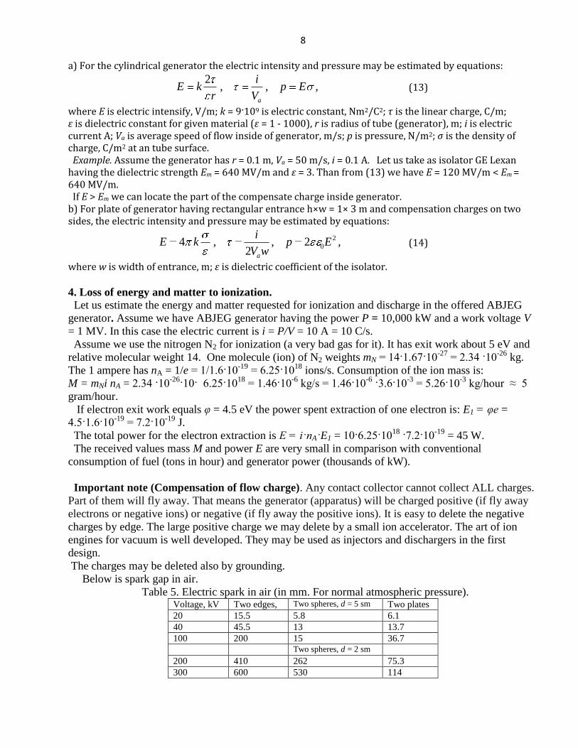
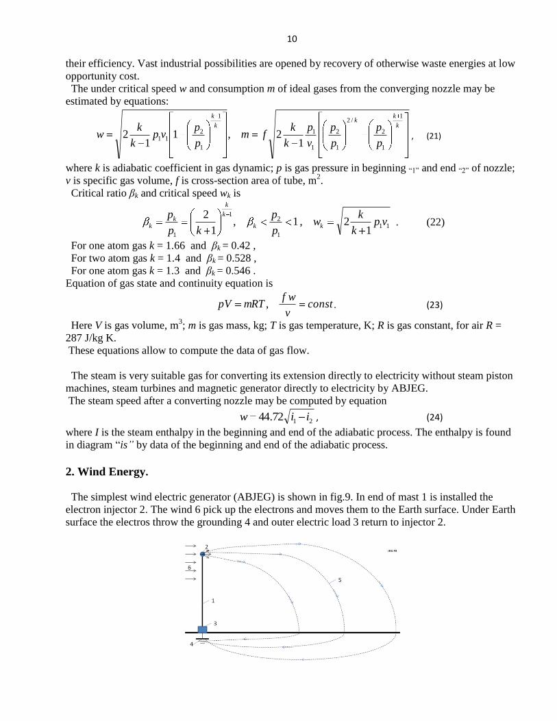