Embed Size (px)
Citation preview

JESUS S. ALFARO
design portfolio
photography 06.
contents 00.
building envelope studio 01.
structure studio 02.
san francisco studio 03.
surface studio 04.
complex object studio 05.
physical model studies 07.
delineation 08.
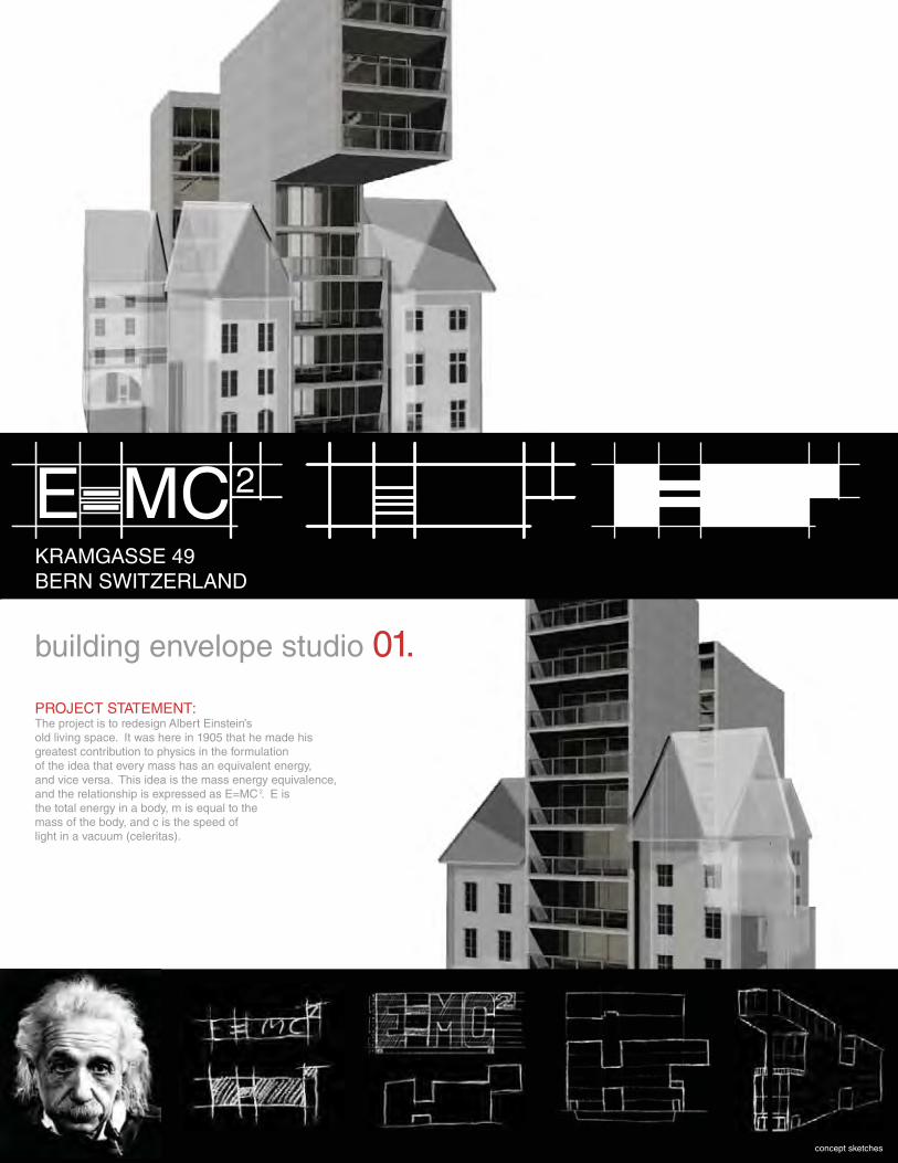
PROJECT STATEMENT:The project is to redesign Albert Einstein’s old living space. It was here in 1905 that he made his greatest contribution to physics in the formulation of the idea that every mass has an equivalent energy, and vice versa. This idea is the mass energy equivalence, and the relationship is expressed as E=MC . E is the total energy in a body, m is equal to the mass of the body, and c is the speed of light in a vacuum (celeritas).
concept sketches
2
2
E=MC2
KRAMGASSE 49BERN SWITZERLAND
building envelope studio 01.
2
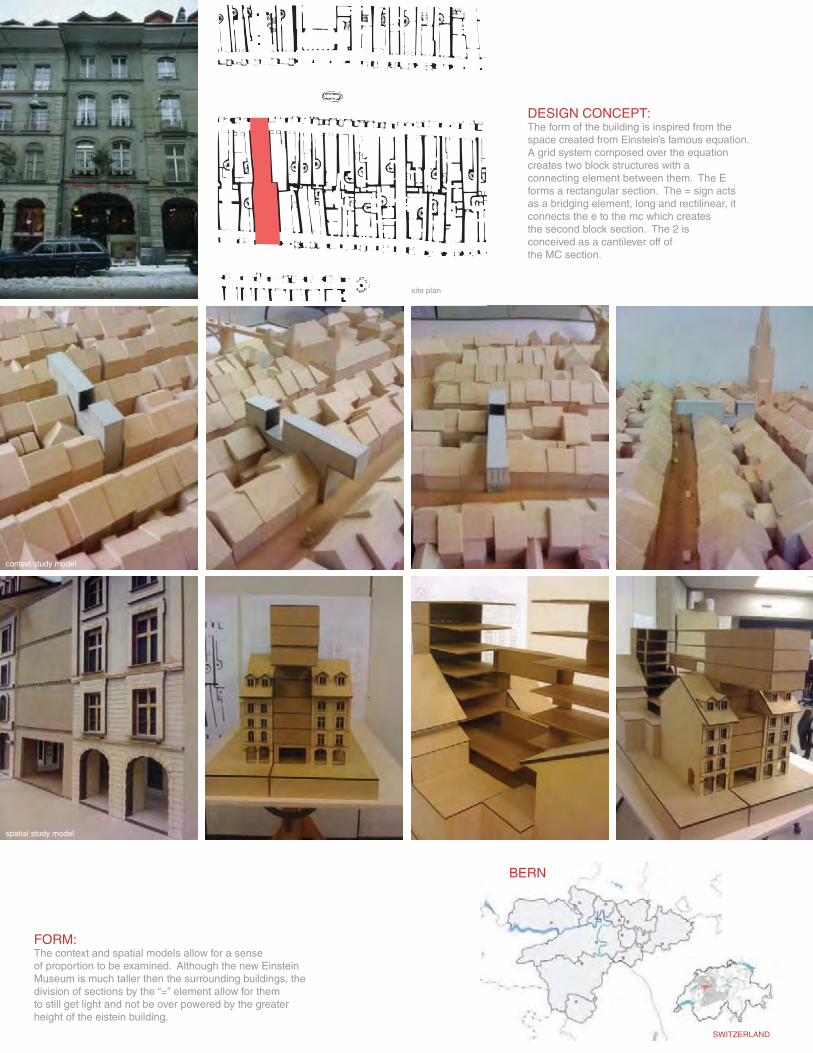
context study model
spatial study model
SWITZERLAND
BERN
DESIGN CONCEPT:The form of the building is inspired from the space created from Einstein’s famous equation. A grid system composed over the equation creates two block structures with a connecting element between them. The Eforms a rectangular section. The = sign acts as a bridging element, long and rectilinear, it connects the e to the mc which creates the second block section. The 2 is conceived as a cantilever off of the MC section.
site plan
FORM:The context and spatial models allow for a senseof proportion to be examined. Although the new EinsteinMuseum is much taller then the surrounding buildings, thedivision of sections by the “=” element allow for themto still get light and not be over powered by the greaterheight of the eistein building.
F
DW
DW
DW
R
R
F
DW
1' 5' 10'
roof9th 8th 7th 6th 5th 4th 3rd 2nd ground basement
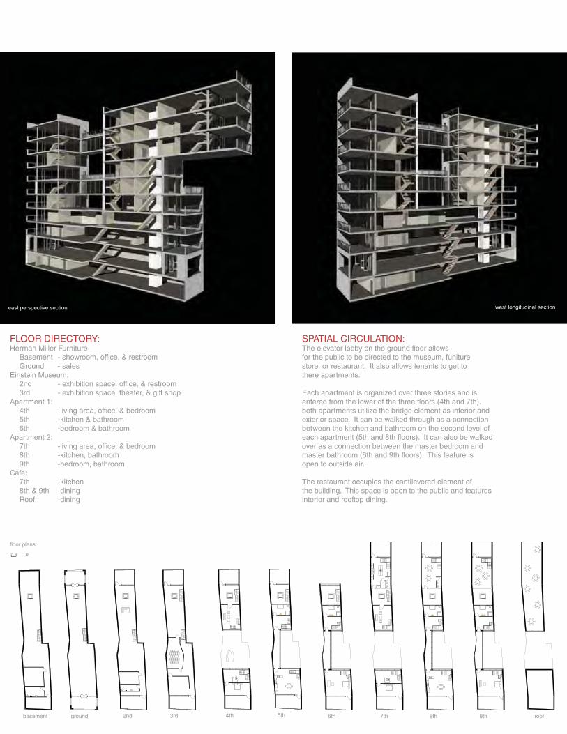
floor plans:
east perspective section west longitudinal section
FLOOR DIRECTORY:Herman Miller Furniture Basement - showroom, office, & restroom Ground - salesEinstein Museum: 2nd - exhibition space, office, & restroom 3rd - exhibition space, theater, & gift shopApartment 1: 4th -living area, office, & bedroom 5th -kitchen & bathroom 6th -bedroom & bathroomApartment 2: 7th -living area, office, & bedroom 8th -kitchen, bathroom 9th -bedroom, bathroomCafe: 7th -kitchen 8th & 9th -dining Roof: -dining
SPATIAL CIRCULATION:The elevator lobby on the ground floor allows for the public to be directed to the museum, funiture store, or restaurant. It also allows tenants to get to there apartments.
Each apartment is organized over three stories and isentered from the lower of the three floors (4th and 7th). both apartments utilize the bridge element as interior and exterior space. It can be walked through as a connection between the kitchen and bathroom on the second level of each apartment (5th and 8th floors). It can also be walked over as a connection between the master bedroom and master bathroom (6th and 9th floors). This feature is open to outside air.
The restaurant occupies the cantilevered element of the building. This space is open to the public and features interior and rooftop dining.
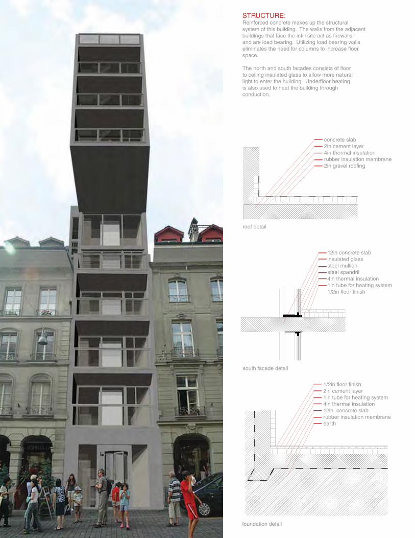
roof detail
south facade detail
foundation detail
concrete slab2in cement layer4in thermal insulationrubber insulation membrane2in gravel roofing
12in concrete slabinsulated glasssteel mullionsteel spandril4in thermal insulation1in tube for heating system1/2in floor finish
1/2in floor finish2in cement layer1in tube for heating system4in thermal insulation12in concrete slabrubber insulation membraneearth
STRUCTURE:Reinforced concrete makes up the structuralsystem of this building. The walls from the adjacentbuildings that face the infill site act as firewallsand are load bearing. Utilizing load bearing wallseliminates the need for columns to increase floorspace.
The north and south facades consists of floor to ceiling insulated glass to allow more natural light to enter the building. Underfloor heating is also used to heat the building through conduction.
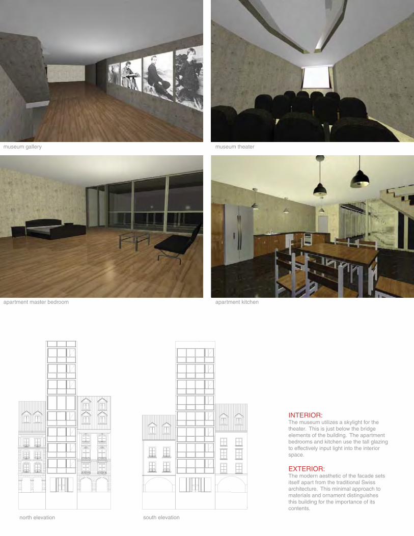
museum gallery museum theater
apartment master bedroom apartment kitchen
north elevation south elevation
INTERIOR:The museum utilizes a skylight for the theater. This is just below the bridgeelements of the building. The apartmentbedrooms and kitchen use the tall glazingto effectively input light into the interior space.
EXTERIOR:The modern aesthetic of the facade sets itself apart from the traditional Swiss architecture. This minimal approach tomaterials and ornament distinguishesthis building for the importance of itscontents.
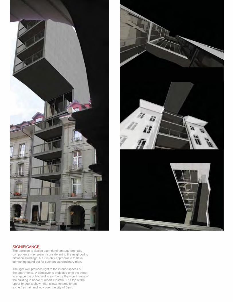
SIGNIFICANCE:The decision to design such dominant and dramaticcomponents may seem inconsiderant to the neighboringhistorical buildings, but it is only approproate to have something stand out for such an extraordinary man.
The light well provides light to the interior spaces of the apartments. A cantilever is projected onto the street to engage the public and to symbolize the significance of the building in honor of Albert Einstein. The top of the upper bridge is shown that allows tenants to get some fresh air and look over the city of Bern.
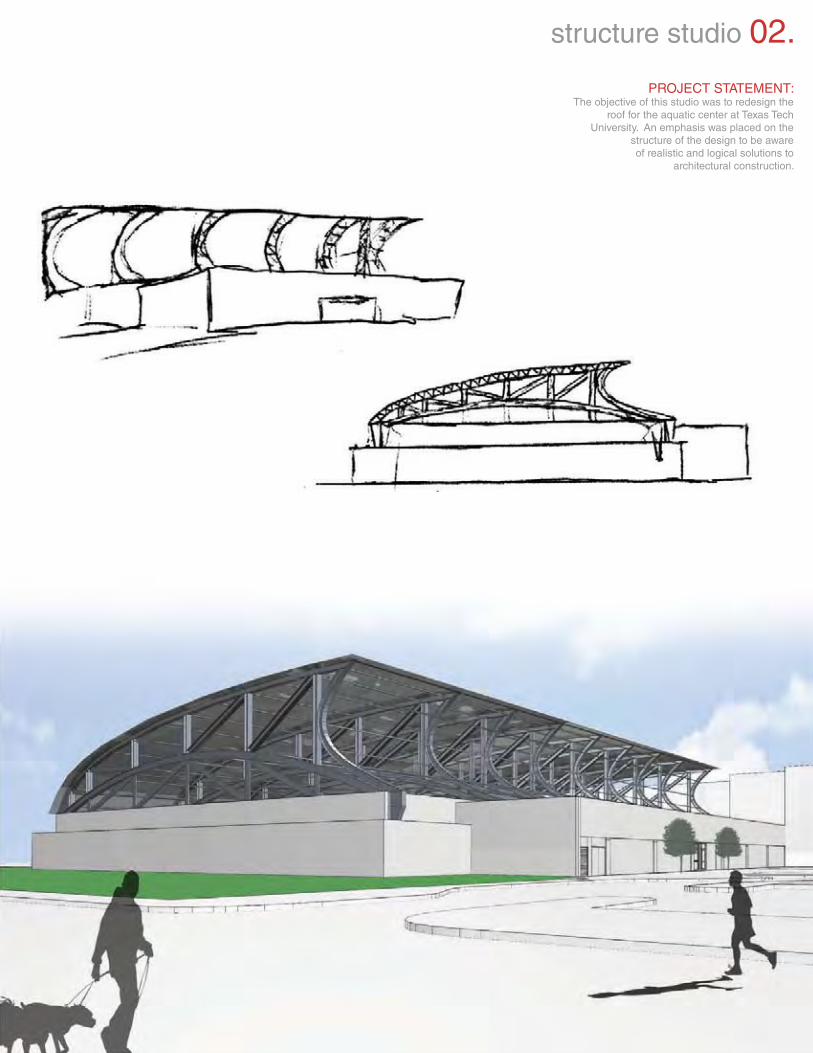
PROJECT STATEMENT:The objective of this studio was to redesign the
roof for the aquatic center at Texas TechUniversity. An emphasis was placed on the
structure of the design to be awareof realistic and logical solutions to
architectural construction.
structure studio 02.
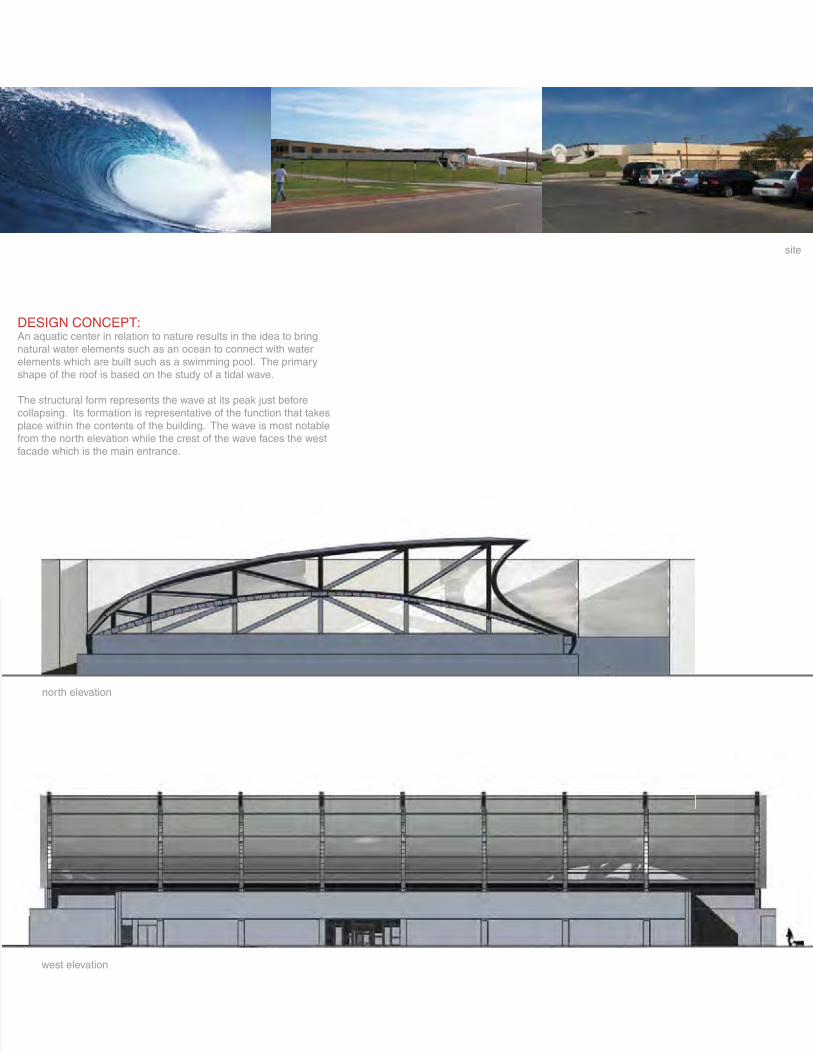
west elevation
north elevation
site
DESIGN CONCEPT:An aquatic center in relation to nature results in the idea to bring natural water elements such as an ocean to connect with water elements which are built such as a swimming pool. The primary shape of the roof is based on the study of a tidal wave.
The structural form represents the wave at its peak just before collapsing. Its formation is representative of the function that takes place within the contents of the building. The wave is most notable from the north elevation while the crest of the wave faces the west facade which is the main entrance.
1
2
3
4
5
7
6
8 9
10
11
13
12
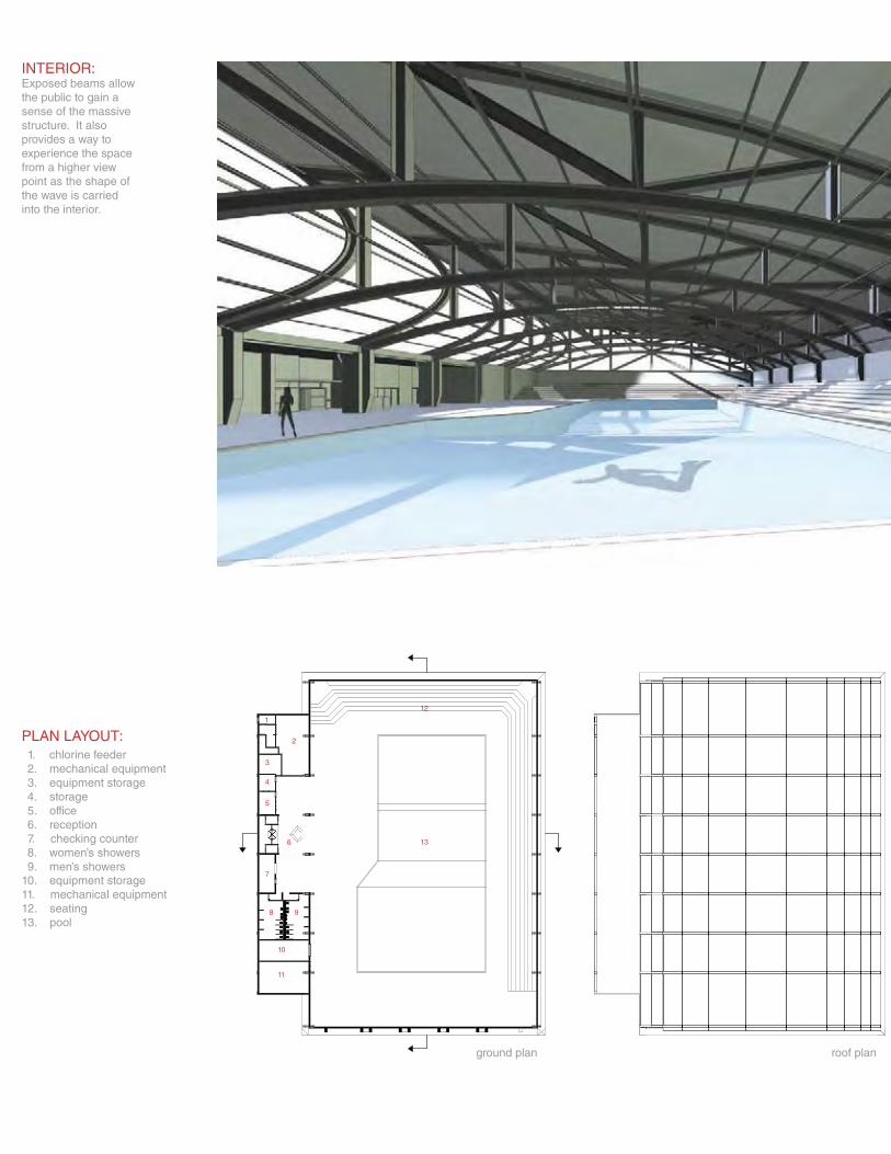
INTERIOR:Exposed beams allowthe public to gain a sense of the massive structure. It also provides a way toexperience the space from a higher view point as the shape of the wave is carried into the interior.
PLAN LAYOUT:
10. equipment storage11. mechanical equipment12. seating13. pool
1. chlorine feeder2. mechanical equipment3. equipment storage4. storage5. office6. reception7. checking counter8. women’s showers9. men’s showers
ground plan roof plan
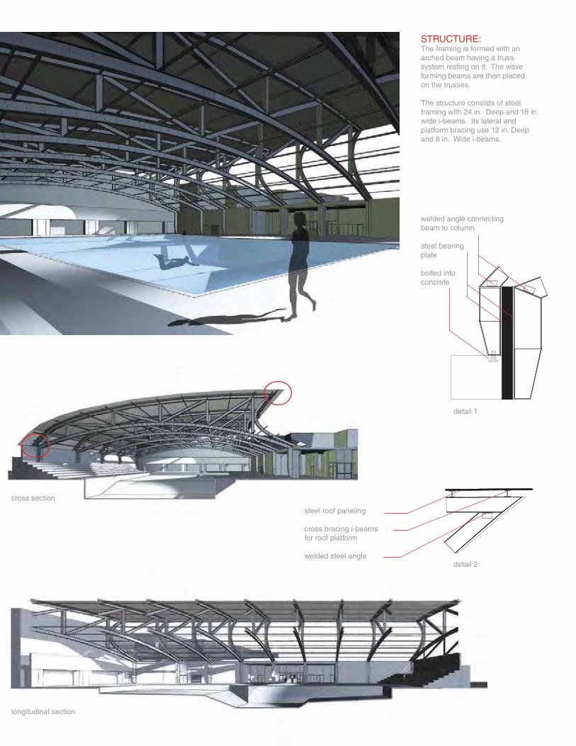
longitudinal section
cross section
detail 1
detail 2
welded angle connecting beam to column
steel bearing plate
bolted intoconcrete
steel roof paneling
cross bracing i-beamsfor roof platform
welded steel angle
STRUCTURE:The framing is formed with anarched beam having a trusssystem resting on it. The waveforming beams are then placedon the trusses.
The structure consists of steelframing with 24 in. Deep and 18 in.wide i-beams. Its lateral andplatform bracing use 12 in. Deepand 8 in. Wide i-beams.
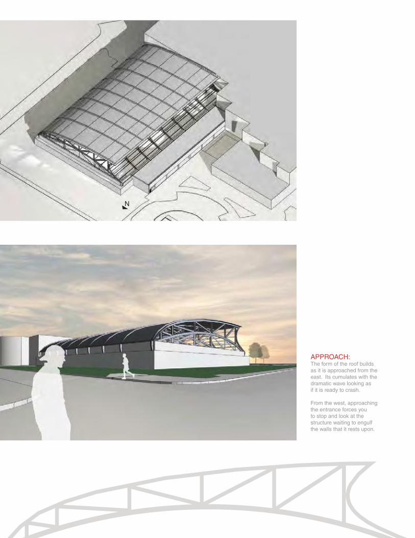
APPROACH:The form of the roof builds as it is approached from the east. Its cumulates with the dramatic wave looking as if it is ready to crash.
From the west, approaching the entrance forces you to stop and look at the structure waiting to engulf the walls that it rests upon.
N
san francisco studio 03.
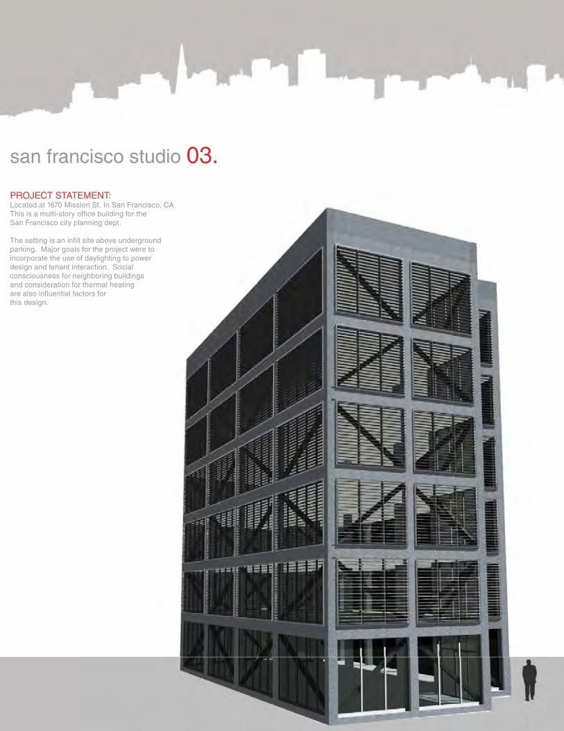
PROJECT STATEMENT:Located at 1670 Mission St. In San Francisco, CA.This is a multi-story office building for the San Francisco city planning dept.
The setting is an infill site above underground parking. Major goals for the project were to incorporate the use of daylighting to power design and tenant interaction. Socialconsciousness for neighboring buildings and consideration for thermal heating are also influential factors forthis design.
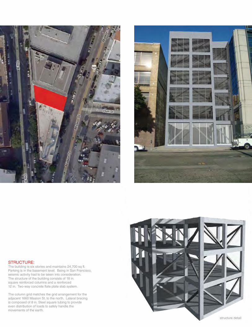
STRUCTURE:The building is six stories and maintains 24,700 sq ft.Parking is in the basement level. Being in San Francisco,seismic activity had to be taken into consideration. The structure of the building consists of 18 in. square reinforced columns and a reinforced 12 in. Two-way concrete flate plate slab system.
The column grid matches the grid arrangement for the adjacent 1660 Mission St. to the north. Lateral bracing is composed of 8 in. Steel square tubing to provide even distribution of loads to safely handle the movements of the earth.
structure detail
N
44'-3 1/4"
95'-2
3/4
"
14'-4
1/4
"15
'-9 3
/4"
ELEV. 1
ELEV. 2
STAIR 1
STAIR
RR
LOBBY
1670 MISSION1660 MISSION
JAN.
ELECT.
LOBBY
MEN
WOMEN
STAIR
RR
CONFERENCE
OFFICE SPACE
OFFICE SPACE
JAN.
STAIR
RR
PRIVATEOFFICE
PRIVATEOFFICE
OFFICE SPACE
OFFICE SPACE
JAN.
STAIR
RR
OFFICE SPACE
OFFICE SPACE
JAN.
F
STAIR
RR
BREAK ROOM
OFFICE SPACELOBBY SPACE
OFFICE SPACE
JAN.
STAIR
RR
JAN.
N
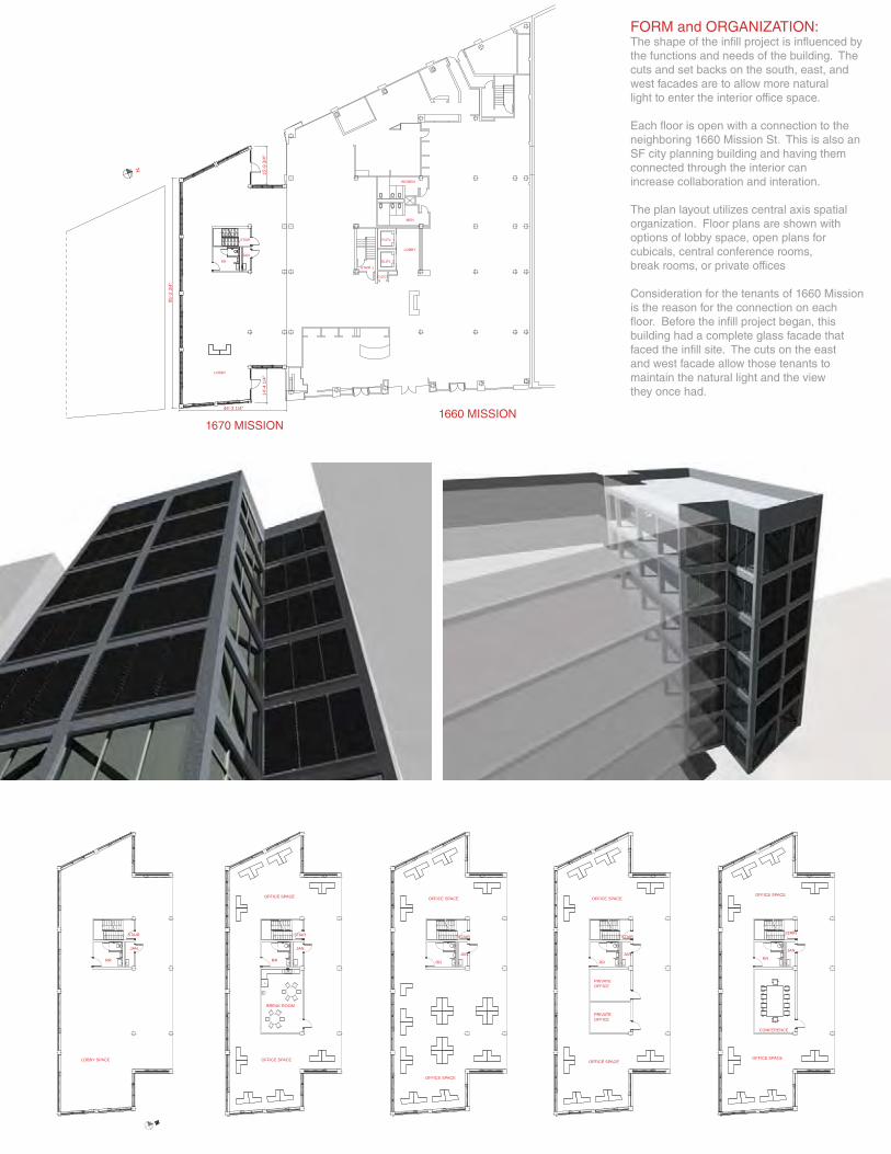
FORM and ORGANIZATION:The shape of the infill project is influenced by the functions and needs of the building. The cuts and set backs on the south, east, and west facades are to allow more natural light to enter the interior office space.
Each floor is open with a connection to the neighboring 1660 Mission St. This is also an SF city planning building and having them connected through the interior canincrease collaboration and interation.
The plan layout utilizes central axis spatial organization. Floor plans are shown with options of lobby space, open plans for cubicals, central conference rooms,break rooms, or private offices
Consideration for the tenants of 1660 Mission is the reason for the connection on each floor. Before the infill project began, this building had a complete glass facade that faced the infill site. The cuts on the east and west facade allow those tenants to maintain the natural light and the view they once had.
COUPLING
FRAME
ELECTRONICACTUATOR
LOUVER
GLAZING
HAND PULLEY
FRAME
LOUVER
GLAZING
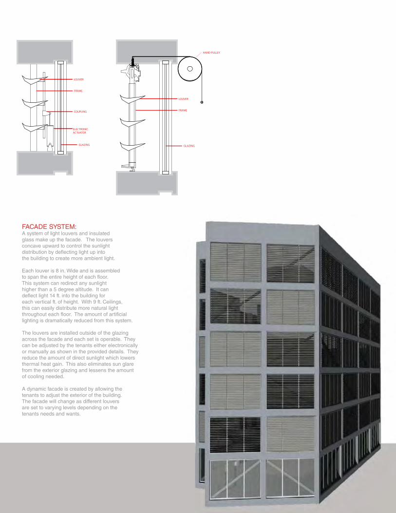
FACADE SYSTEM:A system of light louvers and insulated glass make up the facade. The louvers concave upward to control the sunlight distribution by deflecting light up into the building to create more ambient light.
Each louver is 8 in. Wide and is assembled to span the entire height of each floor. This system can redirect any sunlight higher than a 5 degree altitude. It can deflect light 14 ft. into the building for each vertical ft. of height. With 9 ft. Ceilings, this can easily distribute more natural light throughout each floor. The amount of artificial lighting is dramatically reduced from this system.
The louvers are installed outside of the glazing across the facade and each set is operable. They can be adjusted by the tenants either electronically or manually as shown in the provided details. They reduce the amount of direct sunlight which lowers thermal heat gain. This also eliminates sun glare from the exterior glazing and lessens the amount of cooling needed.
A dynamic facade is created by allowing the tenants to adjust the exterior of the building. The facade will change as different louvers are set to varying levels depending on the tenants needs and wants.
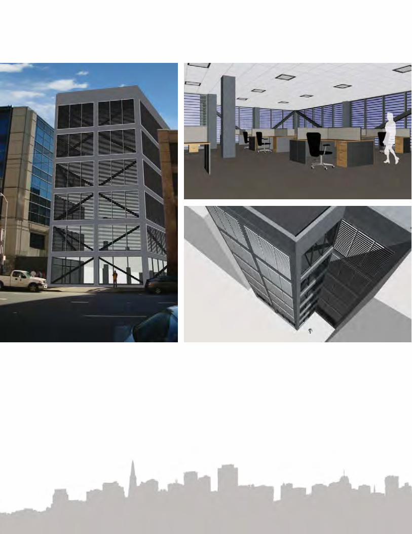
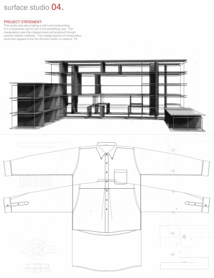
PROJECT STATEMENT:This studio was about taking a shirt and manipulatingit in a systematic way to turn it into something new. Themanipulation was then diagrammed and analyzed through several notation methods. The notated sytems of manipulation were then applied to the Jim Kimmel Center in Lubbock, TX.
surface studio 04.
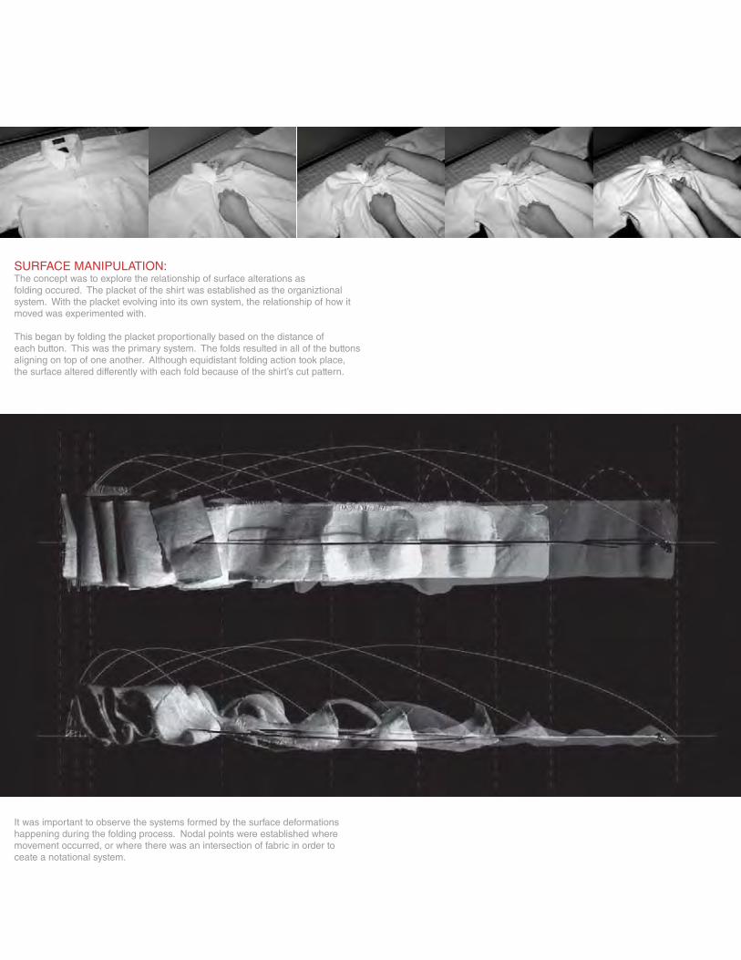
SURFACE MANIPULATION:The concept was to explore the relationship of surface alterations as folding occured. The placket of the shirt was established as the organiztional system. With the placket evolving into its own system, the relationship of how it moved was experimented with.
This began by folding the placket proportionally based on the distance of each button. This was the primary system. The folds resulted in all of the buttons aligning on top of one another. Although equidistant folding action took place, the surface altered differently with each fold because of the shirt’s cut pattern.
It was important to observe the systems formed by the surface deformations happening during the folding process. Nodal points were established where movement occurred, or where there was an intersection of fabric in order toceate a notational system.
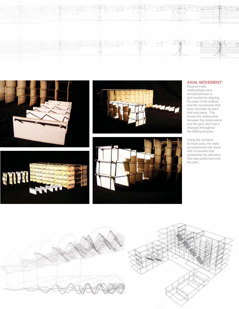
AXIAL MOVEMENT:Diagrammatic relationships were formed between a grid created by aligning the axes of the buttons, and the movements that were recorded as each fold took place. This shows the relationship between the nodal points and the grid, and how it changed throughout the folding process.
Using the corridors as focal axes, the wallsare positioned into placewith movement that represents the alterationthat was performed onto the shirt.
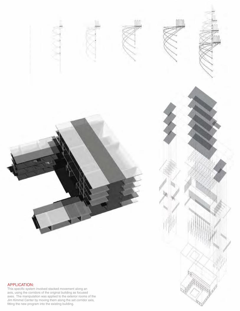
APPLICATION:This specific system involved stacked movement along an axis, using the corridors of the original building as focused axes. The manipulation was applied to the exterior rooms of the Jim Kimmel Center by moving them along the set corridor axis, fitting the new program into the existing building.
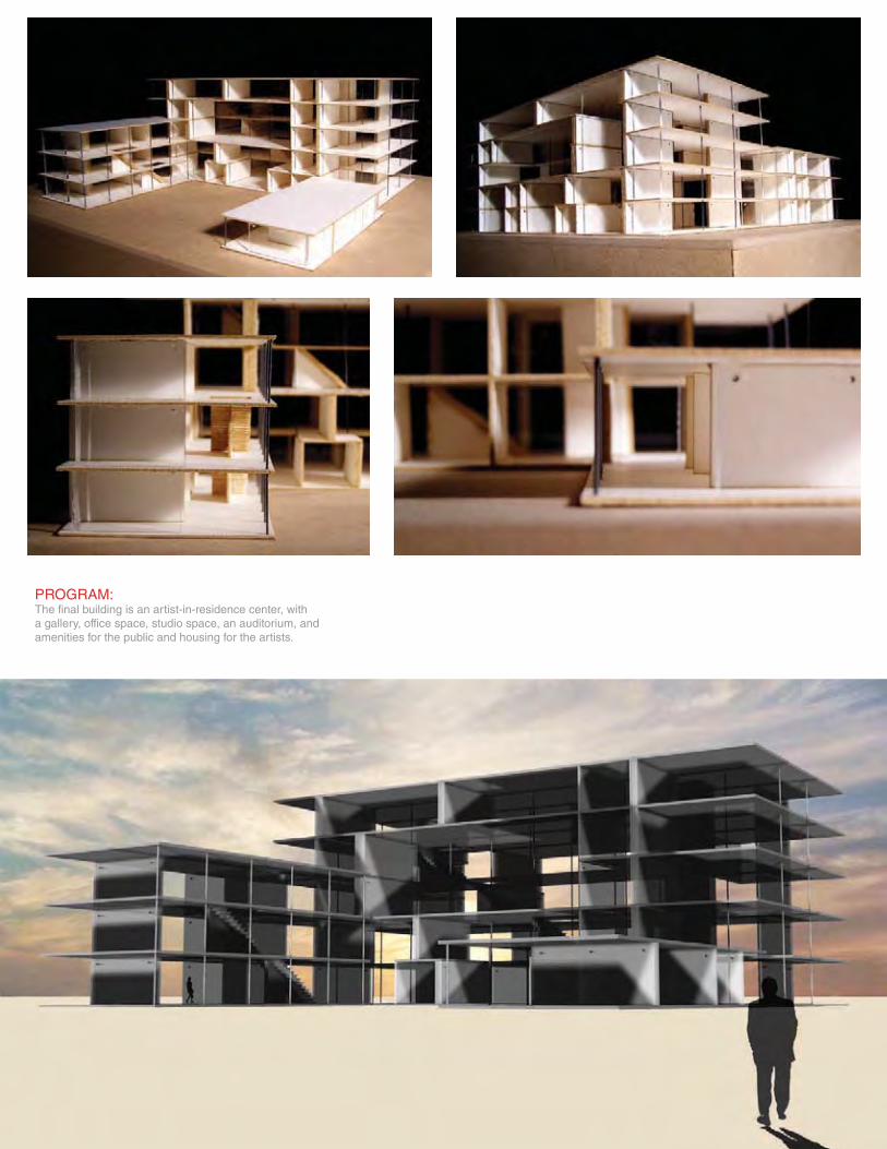
PROGRAM:The final building is an artist-in-residence center, witha gallery, office space, studio space, an auditorium, andamenities for the public and housing for the artists.
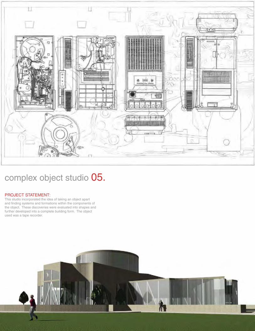
PROJECT STATEMENT:This studio incorporated the idea of taking an object apart and finding systems and formations within the components of the object. These discoveries were evaluated into shapes and further developed into a complete building form. The object used was a tape recorder.
complex object studio 05.
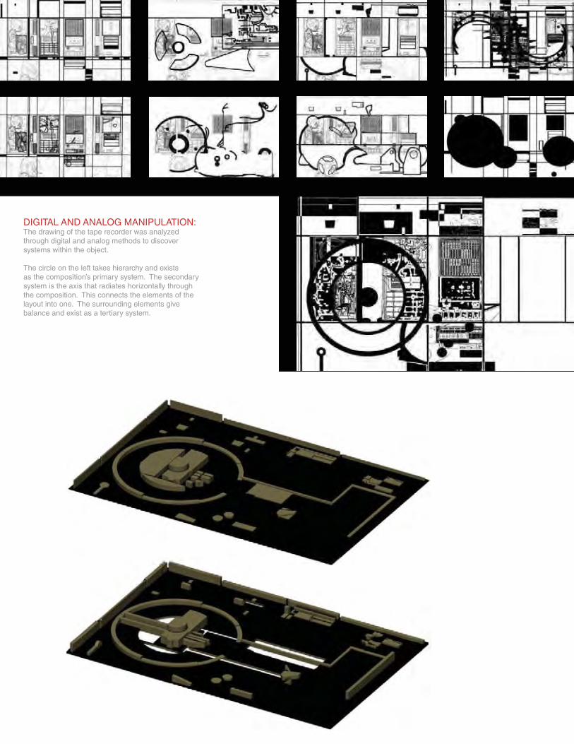
DIGITAL AND ANALOG MANIPULATION:The drawing of the tape recorder was analyzed through digital and analog methods to discover systems within the object.
The circle on the left takes hierarchy and exists as the composition’s primary system. The secondary system is the axis that radiates horizontally through the composition. This connects the elements of the layout into one. The surrounding elements give balance and exist as a tertiary system.
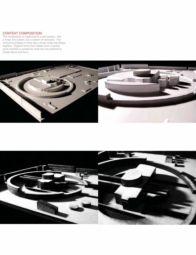
CONTEXT COMPOSITION:The composition is organized by a grid system. Nota linear line system, but a system of remnants. Theremaining shapes of what was a linear holds the designtogether. Organic forms that radiate from a centralpoint maintain a context for what has the potential tocreate space and form.
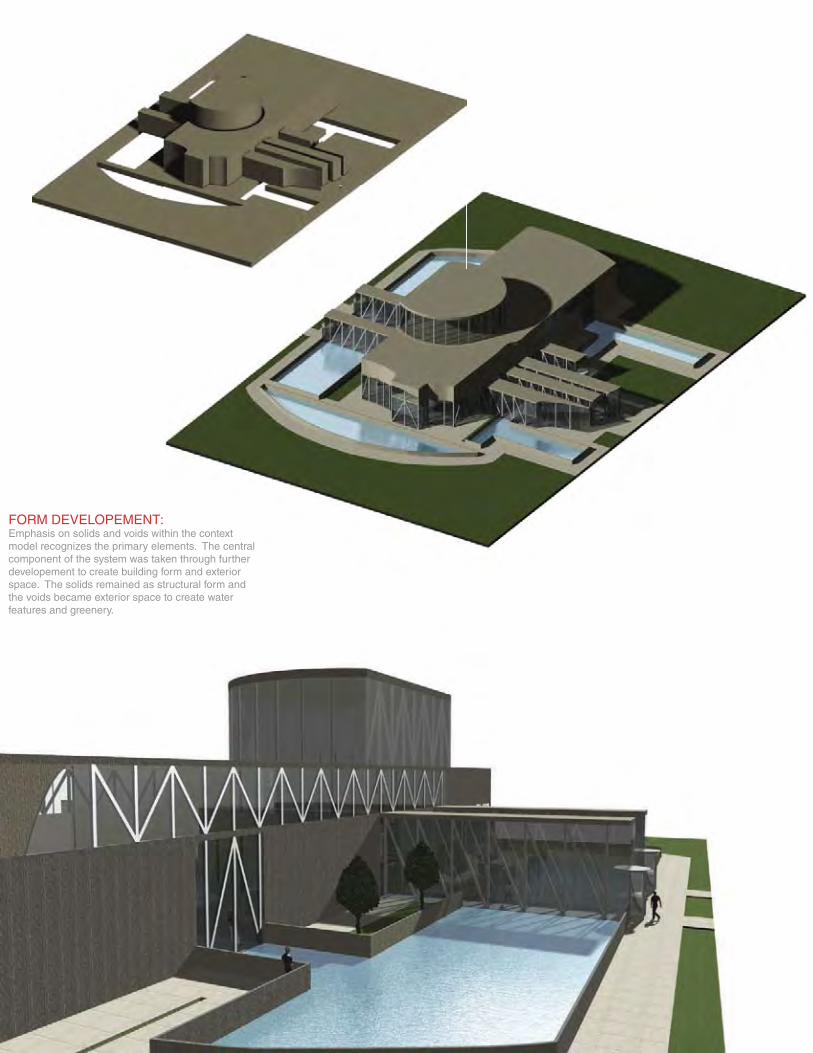
FORM DEVELOPEMENT:Emphasis on solids and voids within the contextmodel recognizes the primary elements. The central component of the system was taken through further developement to create building form and exterior space. The solids remained as structural form and the voids became exterior space to create water features and greenery.
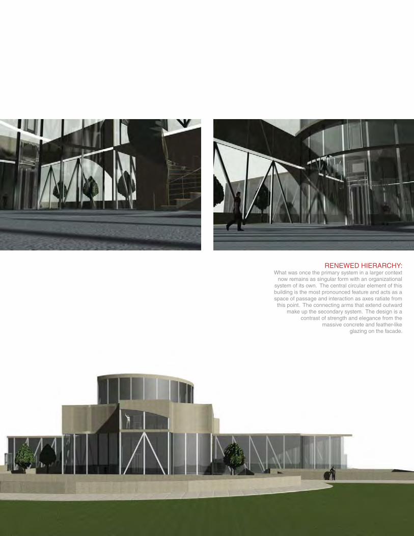
RENEWED HIERARCHY:What was once the primary system in a larger context
now remains as singular form with an organizationalsystem of its own. The central circular element of thisbuilding is the most pronounced feature and acts as aspace of passage and interaction as axes ratiate fromthis point. The connecting arms that extend outward
make up the secondary system. The design is acontrast of strength and elegance from the
massive concrete and feather-likeglazing on the facade.
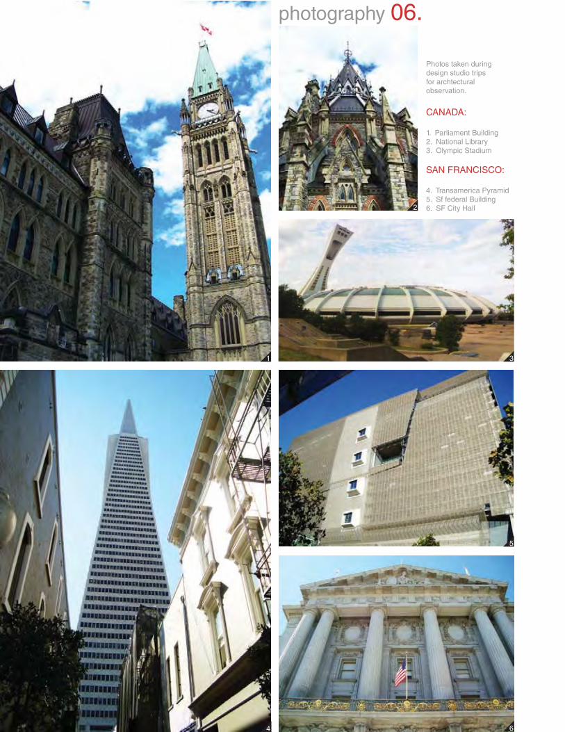
Photos taken duringdesign studio tripsfor archtecturalobservation.
CANADA:
1. Parliament Building2. National Library3. Olympic Stadium
SAN FRANCISCO:
4. Transamerica Pyramid5. Sf federal Building6. SF City Hall
photography 06.
1
4
3
5
6
2
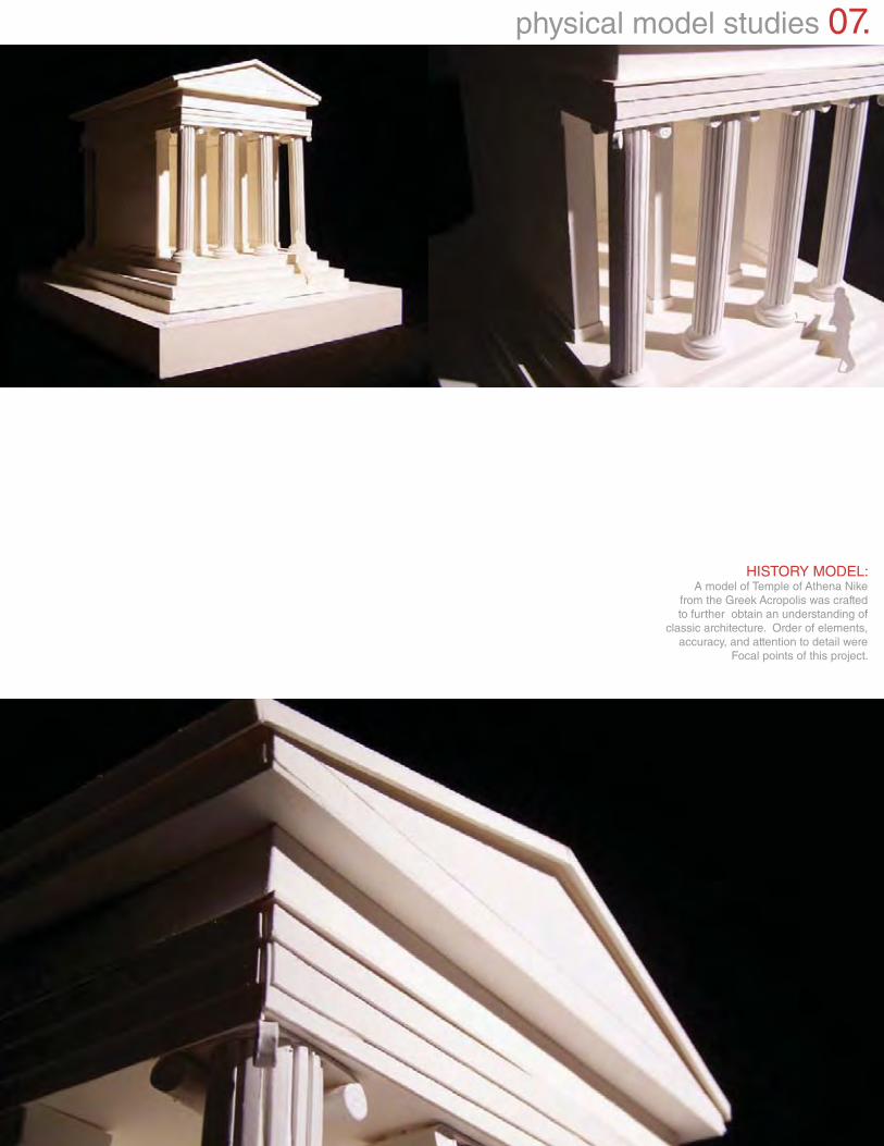
HISTORY MODEL:A model of Temple of Athena Nike
from the Greek Acropolis was craftedto further obtain an understanding of
classic architecture. Order of elements,accuracy, and attention to detail were
Focal points of this project.
physical model studies 07.
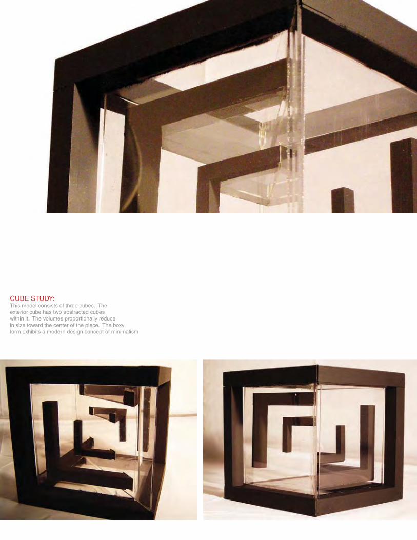
CUBE STUDY:This model consists of three cubes. Theexterior cube has two abstracted cubeswithin it. The volumes proportionally reduce in size toward the center of the piece. The boxy form exhibits a modern design concept of minimalism
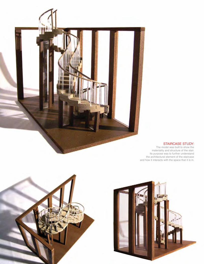
STAIRCASE STUDY:The model was built to show the
materiality and structure of the stair.Its purpose was to further understand
the architectural element of the staircaseand how it interacts with the space that it is in.
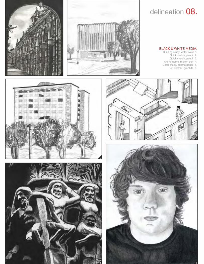
BLACK & WHITE MEDIA:Building study, water color 1.
Quick sketch, pencil 2.Quick sketch, pencil 3.
Axonometric, micron pen 4.Detail study, prisma pencil 5.
Self portrait, graphite 6.
1
4
2
5 6
3
delineation 08.
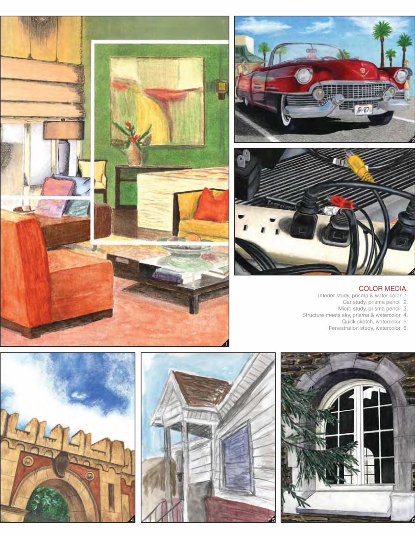
COLOR MEDIA:Interior study, prisma & water color 1.
Car study, prisma pencil 2.Micro study, prisma pencil 3.
Structure meets sky, prisma & watercolor 4.Quick sketch, watercolor 5.
Fenestration study, watercolor 6.
1
4
2
5 6
3

2013
JESUS S. ALFARO