Embed Size (px)
Citation preview
Jesuit High SchoolCarmichael, CAMATE 2017
Carson Black ‘17 - Mechanical EngineerAndrew Chang ‘17 - Electrical Engineer, Electronics Lead, CEONick Ellis ‘17 - Mechanical Engineer, Mechanical Design LeadMatthew Kiyama ‘17 - Software Engineer, Research and Development LeadSam Kreifels ‘17 - Mechanical Engineer, Manufacturing LeadCassidy Nguyen ‘17 - Software Engineer, Software LeadDrake Charamuga ‘18 - Mechanical EngineerSam Paragary ‘18 - Marketing and Publications LeadNoah Pettinato ‘18 - Software EngineerRisheek Pingili ‘18 - Software EngineerGavin Remme ‘18 - Marketing and Publications, Safety OfficerDaniel Brennan ‘19 - Mechanical EngineerAdam Graham ‘19 - Software EngineerHayden Kaufman* ‘19 - Electrical EngineerAustin Law ‘19 - 3D Modeling/CAD LeadJames Monroe* ‘19 - Mechanical EngineerJames Whitcomb-Weston ‘19 - Mechanical EngineerAlex Cherry ‘20* - Mechanical EngineerMichael Equi* ‘20 - Electrical EngineerAidan French* ‘20 - Software EngineerCaelin Sutch* ‘20 - Marketing and PublicationsJay Isaacs - Head CoachSteve Kiyama - Assistant Coach*New Members (all other members are returning)
CAD rendering of Lazarus
Jesuit Robotics
jesuitrobotics.com 2017 Technical Documentation | Page 2
Table of ContentsI. Introduction 3
A. Abstract 3II. Design Rationale 4
A. Design Evolution 4B. Mechanical Design and Manufacturing Process 5C. Mechanical Components 6D. Electrical Systems 8E. Pneumatics 10F. Software 11G. Tools 12H. Product Demonstration 15I. Troubleshooting and Testing Techniques 16
III. Safety 17A. Company Safety Philosophy 17B. Lab Protocols 17C. Training 17D. Vehicle Safety Features 18E. Operational and Safety Checklists 18
IV. Logistics 18A. Scheduled Project Management 18B. Company Organization and Assignments 19C. Collaborative Workspace 19D. Source Code Management 19E. Budget and Project Costing 19
V. Conclusion 20A. Challenges 20B. Lessons Learned and Skills Gained 21C. Future Improvements 21D. Senior Reflections 21E. Acknowledgements 23F. References 23G. Photo Credits 23
VI. Appendices 24A. Software Flowcharts 24B. Operational and Safety Checklists 25
jesuitrobotics.com 2017 Technical Documentation | Page 3
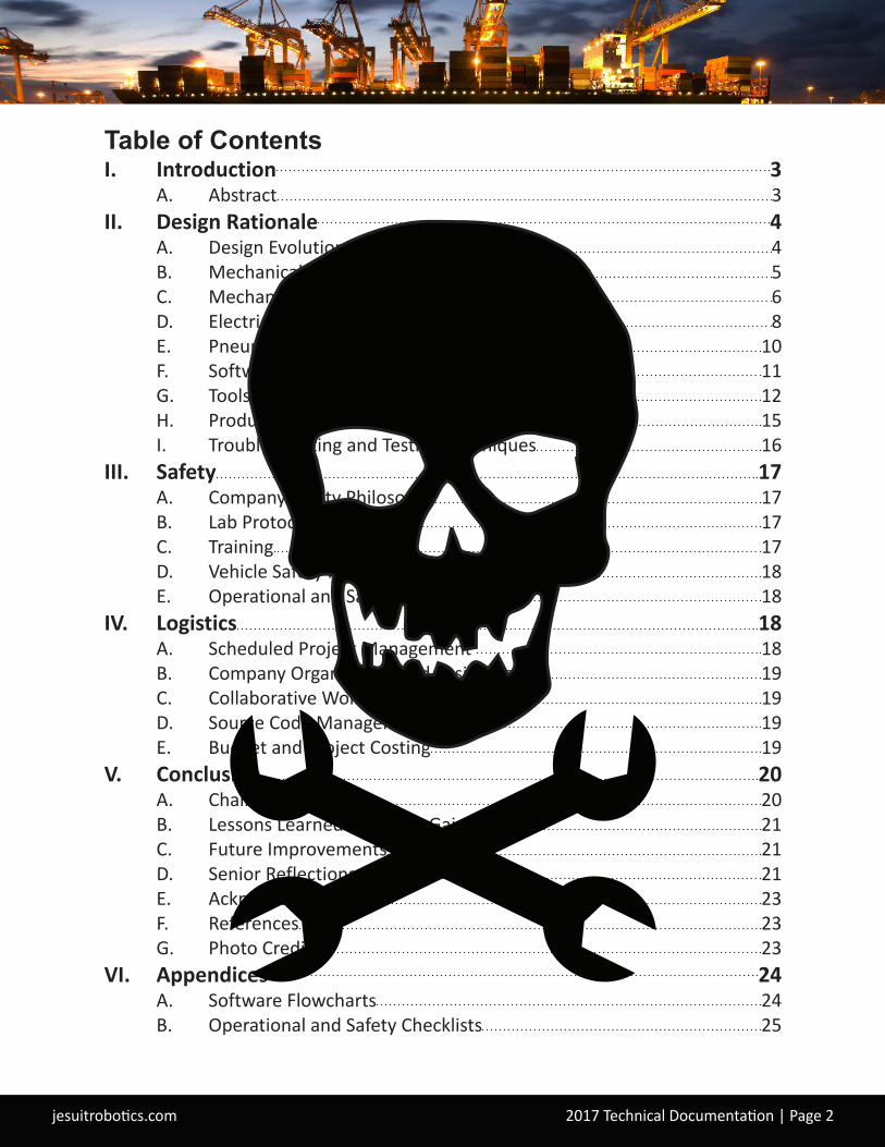
I. IntroductionA. AbstractRovotics’ newest innovation, Lazarus, is an underwater Remotely Operated Vehicle (ROV) designed to perform a variety of tasks within the Port of Long Beach. Lazarus is fully equipped with tools to assist in the construction of a hyperloop cargo transportation system, maintain the port’s fountains, identify contaminants as part of the port’s cleanup program, and locate and mark sunken freight containers holding hazardous content.Rovotics has the capability to deliver state-of-the-art ROVs like Lazarus to meet the Port of Long Beach’s needs. Our dedicated, twenty-one person workforce (Figure 1) has the skill and experience to produce ROVs custom-designed to meet specific requirements. Organized into interdependent departments by specialty, Rovotics' program management system allows our company to efficiently oversee product development in a flexible and collaborative way. All designs are produced in-house using advanced manufacturing capabilities such as precision machining with a Computer Numerical Control (CNC) mill, design and assembly of custom-printed circuit boards, 3D printing, and other specialized equipment.Lazarus is the result of months of planning, research and analysis, manufacturing, and testing under strict safety protocols. It was designed to meet specialized size and weight requirements and with increased speed, maneuverability, and power efficiency over previous designs. These features, along with a multifunctional gripper and pilot heads-up display (HUD), make it Rovotics’ most advanced vehicle yet.This technical documentation describes the design and development process that makes Lazarus the best ROV to meet the requirements in the Port of Long Beach Request for Proposals (RFP).
Figure 1. Rovotics 2017 company photo with their newest ROV, Lazarus.
jesuitrobotics.com 2017 Technical Documentation | Page 4
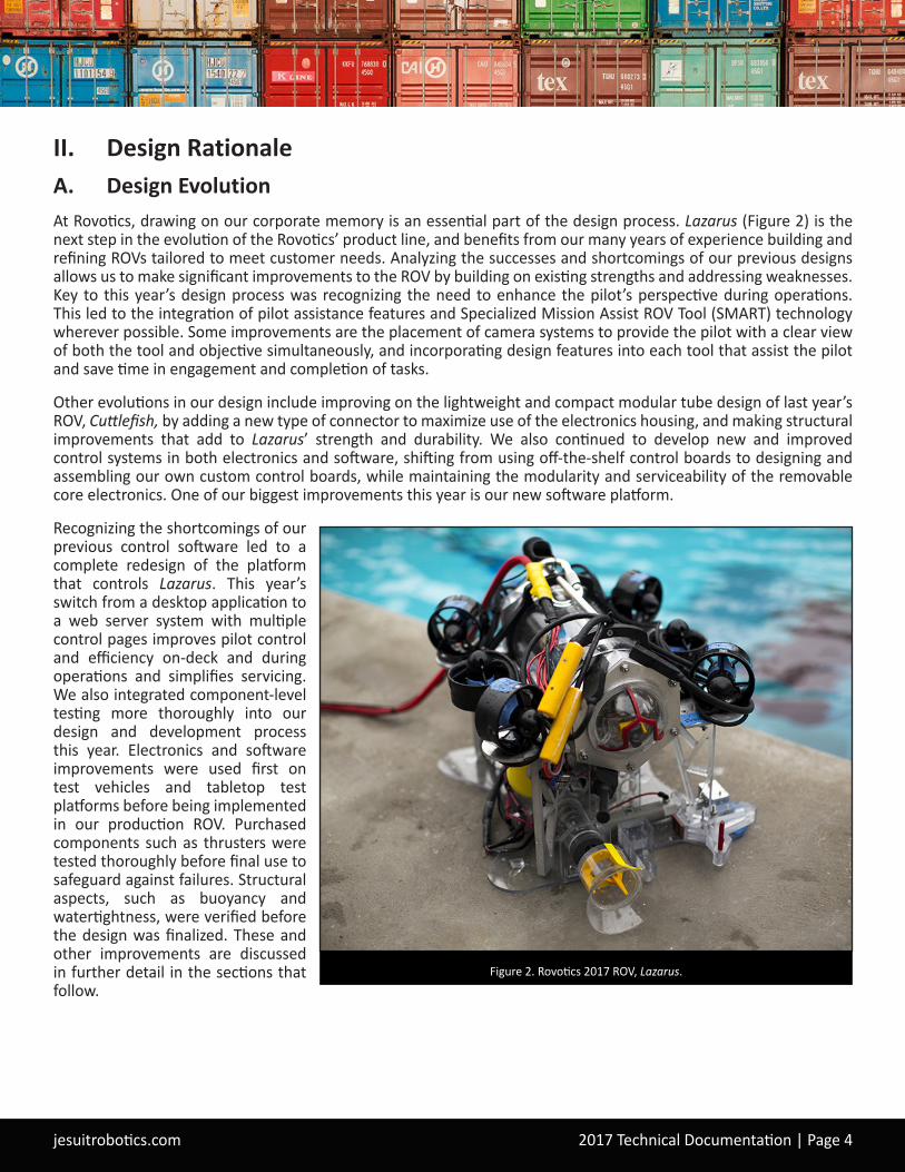
II. Design RationaleA. Design EvolutionAt Rovotics, drawing on our corporate memory is an essential part of the design process. Lazarus (Figure 2) is the next step in the evolution of the Rovotics’ product line, and benefits from our many years of experience building and refining ROVs tailored to meet customer needs. Analyzing the successes and shortcomings of our previous designs allows us to make significant improvements to the ROV by building on existing strengths and addressing weaknesses. Key to this year’s design process was recognizing the need to enhance the pilot’s perspective during operations. This led to the integration of pilot assistance features and Specialized Mission Assist ROV Tool (SMART) technology wherever possible. Some improvements are the placement of camera systems to provide the pilot with a clear view of both the tool and objective simultaneously, and incorporating design features into each tool that assist the pilot and save time in engagement and completion of tasks.
Other evolutions in our design include improving on the lightweight and compact modular tube design of last year’s ROV, Cuttlefish, by adding a new type of connector to maximize use of the electronics housing, and making structural improvements that add to Lazarus’ strength and durability. We also continued to develop new and improved control systems in both electronics and software, shifting from using off-the-shelf control boards to designing and assembling our own custom control boards, while maintaining the modularity and serviceability of the removable core electronics. One of our biggest improvements this year is our new software platform.
Recognizing the shortcomings of our previous control software led to a complete redesign of the platform that controls Lazarus. This year’s switch from a desktop application to a web server system with multiple control pages improves pilot control and efficiency on-deck and during operations and simplifies servicing. We also integrated component-level testing more thoroughly into our design and development process this year. Electronics and software improvements were used first on test vehicles and tabletop test platforms before being implemented in our production ROV. Purchased components such as thrusters were tested thoroughly before final use to safeguard against failures. Structural aspects, such as buoyancy and watertightness, were verified before the design was finalized. These and other improvements are discussed in further detail in the sections that follow.
Figure 2. Rovotics 2017 ROV, Lazarus.
jesuitrobotics.com 2017 Technical Documentation | Page 5
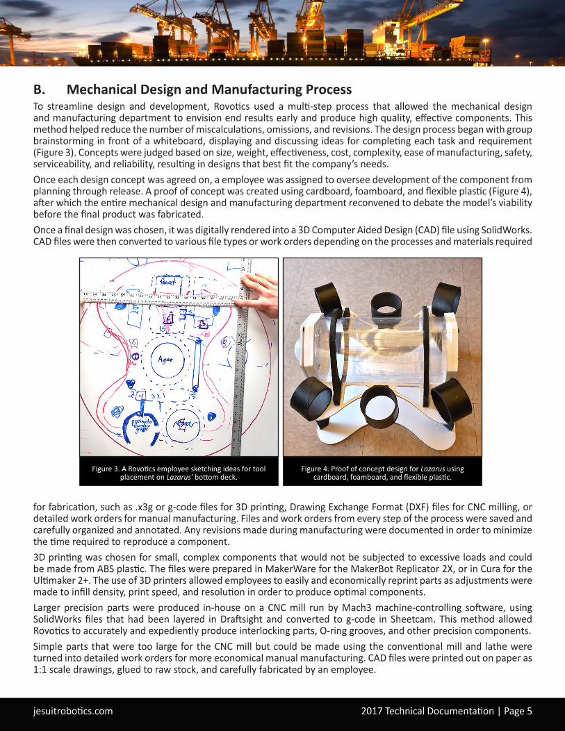
B. Mechanical Design and Manufacturing ProcessTo streamline design and development, Rovotics used a multi-step process that allowed the mechanical design and manufacturing department to envision end results early and produce high quality, effective components. This method helped reduce the number of miscalculations, omissions, and revisions. The design process began with group brainstorming in front of a whiteboard, displaying and discussing ideas for completing each task and requirement (Figure 3). Concepts were judged based on size, weight, effectiveness, cost, complexity, ease of manufacturing, safety, serviceability, and reliability, resulting in designs that best fit the company’s needs.Once each design concept was agreed on, a employee was assigned to oversee development of the component from planning through release. A proof of concept was created using cardboard, foamboard, and flexible plastic (Figure 4), after which the entire mechanical design and manufacturing department reconvened to debate the model’s viability before the final product was fabricated.Once a final design was chosen, it was digitally rendered into a 3D Computer Aided Design (CAD) file using SolidWorks. CAD files were then converted to various file types or work orders depending on the processes and materials required
for fabrication, such as .x3g or g-code files for 3D printing, Drawing Exchange Format (DXF) files for CNC milling, or detailed work orders for manual manufacturing. Files and work orders from every step of the process were saved and carefully organized and annotated. Any revisions made during manufacturing were documented in order to minimize the time required to reproduce a component.3D printing was chosen for small, complex components that would not be subjected to excessive loads and could be made from ABS plastic. The files were prepared in MakerWare for the MakerBot Replicator 2X, or in Cura for the Ultimaker 2+. The use of 3D printers allowed employees to easily and economically reprint parts as adjustments were made to infill density, print speed, and resolution in order to produce optimal components.Larger precision parts were produced in-house on a CNC mill run by Mach3 machine-controlling software, using SolidWorks files that had been layered in Draftsight and converted to g-code in Sheetcam. This method allowed Rovotics to accurately and expediently produce interlocking parts, O-ring grooves, and other precision components.Simple parts that were too large for the CNC mill but could be made using the conventional mill and lathe were turned into detailed work orders for more economical manual manufacturing. CAD files were printed out on paper as 1:1 scale drawings, glued to raw stock, and carefully fabricated by an employee.
Figure 3. A Rovotics employee sketching ideas for tool placement on Lazarus' bottom deck.
Figure 4. Proof of concept design for Lazarus using cardboard, foamboard, and flexible plastic.
jesuitrobotics.com 2017 Technical Documentation | Page 6
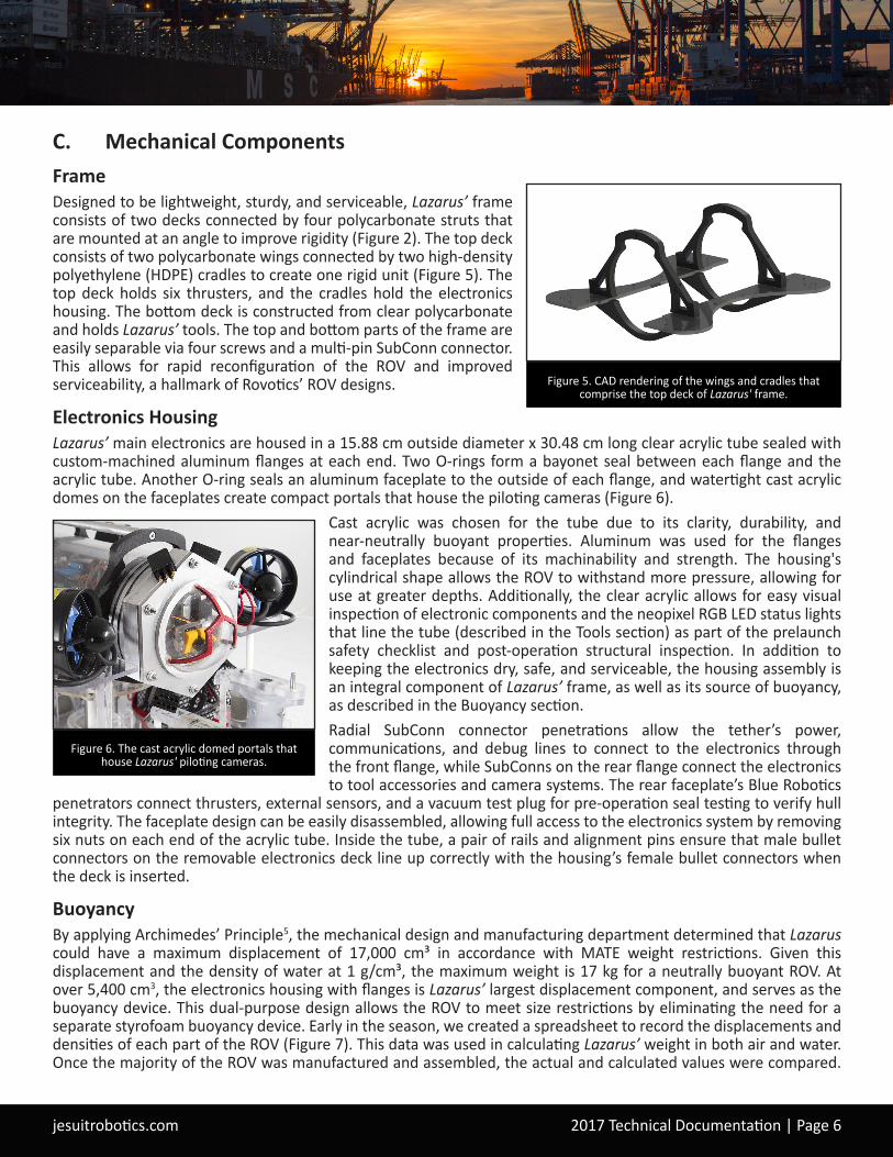
C. Mechanical ComponentsFrameDesigned to be lightweight, sturdy, and serviceable, Lazarus’ frame consists of two decks connected by four polycarbonate struts that are mounted at an angle to improve rigidity (Figure 2). The top deck consists of two polycarbonate wings connected by two high-density polyethylene (HDPE) cradles to create one rigid unit (Figure 5). The top deck holds six thrusters, and the cradles hold the electronics housing. The bottom deck is constructed from clear polycarbonate and holds Lazarus’ tools. The top and bottom parts of the frame are easily separable via four screws and a multi-pin SubConn connector. This allows for rapid reconfiguration of the ROV and improved serviceability, a hallmark of Rovotics’ ROV designs.
Electronics HousingLazarus’ main electronics are housed in a 15.88 cm outside diameter x 30.48 cm long clear acrylic tube sealed with custom-machined aluminum flanges at each end. Two O-rings form a bayonet seal between each flange and the acrylic tube. Another O-ring seals an aluminum faceplate to the outside of each flange, and watertight cast acrylic domes on the faceplates create compact portals that house the piloting cameras (Figure 6).
Cast acrylic was chosen for the tube due to its clarity, durability, and near-neutrally buoyant properties. Aluminum was used for the flanges and faceplates because of its machinability and strength. The housing's cylindrical shape allows the ROV to withstand more pressure, allowing for use at greater depths. Additionally, the clear acrylic allows for easy visual inspection of electronic components and the neopixel RGB LED status lights that line the tube (described in the Tools section) as part of the prelaunch safety checklist and post-operation structural inspection. In addition to keeping the electronics dry, safe, and serviceable, the housing assembly is an integral component of Lazarus’ frame, as well as its source of buoyancy, as described in the Buoyancy section.Radial SubConn connector penetrations allow the tether’s power, communications, and debug lines to connect to the electronics through the front flange, while SubConns on the rear flange connect the electronics to tool accessories and camera systems. The rear faceplate’s Blue Robotics
penetrators connect thrusters, external sensors, and a vacuum test plug for pre-operation seal testing to verify hull integrity. The faceplate design can be easily disassembled, allowing full access to the electronics system by removing six nuts on each end of the acrylic tube. Inside the tube, a pair of rails and alignment pins ensure that male bullet connectors on the removable electronics deck line up correctly with the housing’s female bullet connectors when the deck is inserted.
BuoyancyBy applying Archimedes’ Principle5, the mechanical design and manufacturing department determined that Lazarus could have a maximum displacement of 17,000 cm³ in accordance with MATE weight restrictions. Given this displacement and the density of water at 1 g/cm³, the maximum weight is 17 kg for a neutrally buoyant ROV. At over 5,400 cm3, the electronics housing with flanges is Lazarus’ largest displacement component, and serves as the buoyancy device. This dual-purpose design allows the ROV to meet size restrictions by eliminating the need for a separate styrofoam buoyancy device. Early in the season, we created a spreadsheet to record the displacements and densities of each part of the ROV (Figure 7). This data was used in calculating Lazarus’ weight in both air and water. Once the majority of the ROV was manufactured and assembled, the actual and calculated values were compared.
Figure 5. CAD rendering of the wings and cradles that comprise the top deck of Lazarus' frame.
Figure 6. The cast acrylic domed portals that house Lazarus' piloting cameras.

jesuitrobotics.com 2017 Technical Documentation | Page 7
Lazarus’ weight and buoyancy were then fine-tuned by adjusting the structural and tool materials to bring the center of buoyancy near the horizontal thruster plane. We changed the vertical struts from aluminum to polycarbonate in order to provide a 44.4% reduction in material density while maintaining the same displacement. Lazarus’ tether achieves neutral buoyancy by using aluminum air chambers attached at strategically-spaced increments along its length. These chambers, which have been used successfully on previous generations of Rovotics’ products, have proven to be incompressible at depths exceeding 13 m.
ThrustersLazarus is equipped with six Blue Robotics T100 thrusters1, which were used in Rovotics’ previous ROV design, Cuttlefish. During preventative maintenance on a newly purchased T100 unit, we noticed a design change that warranted the purchase of new units for Lazarus. Each thruster was continuously stress-tested for two hours, far longer than expected service times, to ensure proper thrust capabilities and compatibility with the ROV’s voltage converters. To achieve stable vector control, four thrusters are mounted at 45° angles at the corners of the top deck, allowing all thrusters to contribute to the total propulsion in the cardinal directions and minimizing flow interference with accessories in the center of the vehicle. Two additional thrusters are used for vertical control. Each thruster weighs 295 g in air and produces a maximum forward and reverse thrust of 2.36 kgf and 1.85 kgf, respectively. The thrusters’ operating voltage is 12 V and their maximum operating current is 12.5 A each, well within Lazarus' power budget (Figure 8).
Part Material Density (g/cm^3)
Water Density (g/cm^3)
Material Volume (cm^3)
Displaced Water Volume (cm^3)
Weight of Water Displaced (g) Weight in Air (g) Weight in Water (g)
Core Structure
Top Frame 1.2 1 359 359 359 430.8 71.8Top Cradle (x2) 0.95 1 170.38 170.38 170.38 161.861 -8.519
Bottom Cradle (x2) 0.95 1 130.2 130.2 130.2 123.69 -6.51Front Dome Ring 2.7 1 16.55 16.55 16.55 44.685 28.135Back Dome Ring 2.7 1 14.57 14.57 14.57 39.339 24.769
Thrusters (x6) DNA 1 1177.86 1177.86 1177.86 2286.12 1108.26Posts (x2) 1.2 1 134.34 134.34 134.34 161.208 26.868
Short Post (x1) 1.2 1 61.24 61.24 61.24 73.488 12.248V Thrust Mount (x2) 0.95 1 46.44 46.44 46.44 44.118 -2.322
Strain Relief Assembly 2.7 1 16.17 16.17 16.17 43.659 27.489
Air Trapped Parts
Tube 1.2 1 926.67 6032.99 6032.99 1112.004 -4920.986Front Dome 1.2 1 29.85 274.57 274.57 35.82 -238.75Back Dome 1.2 1 17.58 115.835 115.835 21.096 -94.739
Front Faceplate 2.7 1 80.2 137.39 137.39 216.54 79.15Back Faceplate 2.7 1 99.1 137.39 137.39 267.57 130.18
Front Flange 2.7 1 271.52 554.91 554.91 733.104 178.194Back Flange 2.7 1 271.52 554.91 554.91 733.104 178.194
Internal Elements Electronics DNA 1 120 DNA DNA DNATool Deck Bottom Frame with Tools DNA 1 2750 2800 2800 -2800
Tether Tether minus 1 meter DNA 1 DNA DNA DNA DNATotals 9934.745 4242.086 -3406.539
Figure 7. The component buoyancies spreadsheet used to calculate Lazarus' weight in air and water.
Device Quantity Max. Power (W) per Device Nominal Voltage (V)T100 6 130 12
BlueRobotics ESC 6 6 12Power Converter 2 19.2 48
CPU 1 6 12Servo 2 0.5 5
Camera 10 0.5 5LED Lamps 2 10 12LED Strips 2 5 5
Axis Video Conv. 1 15 48Video Switcher 2 0.1 12
Gripper 1 1 12HandleTurn 1 1 12
Total Power Consumption 898.6Total Available Power at Input SubConn = (MATE Power) - (Tether Power Loss) = 1440 W - 85 W = 1355 WFuse Calculation = (150%) ((Total Max Power Consumption) / (MATE Voltage)) = (150%) (898.6 W / 48 V) = 28.08 A Fuse Value = 30 A
Figure 8. Lazarus' maximum power budget.
jesuitrobotics.com 2017 Technical Documentation | Page 8
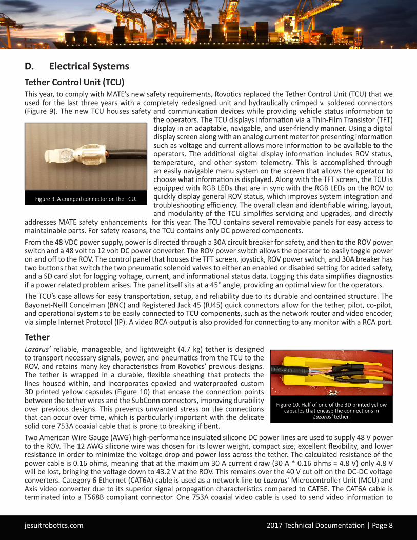
D. Electrical SystemsTether Control Unit (TCU)This year, to comply with MATE’s new safety requirements, Rovotics replaced the Tether Control Unit (TCU) that we used for the last three years with a completely redesigned unit and hydraulically crimped v. soldered connectors (Figure 9). The new TCU houses safety and communication devices while providing vehicle status information to
the operators. The TCU displays information via a Thin-Film Transistor (TFT) display in an adaptable, navigable, and user-friendly manner. Using a digital display screen along with an analog current meter for presenting information such as voltage and current allows more information to be available to the operators. The additional digital display information includes ROV status, temperature, and other system telemetry. This is accomplished through an easily navigable menu system on the screen that allows the operator to choose what information is displayed. Along with the TFT screen, the TCU is equipped with RGB LEDs that are in sync with the RGB LEDs on the ROV to quickly display general ROV status, which improves system integration and troubleshooting efficiency. The overall clean and identifiable wiring, layout, and modularity of the TCU simplifies servicing and upgrades, and directly
addresses MATE safety enhancements for this year. The TCU contains several removable panels for easy access to maintainable parts. For safety reasons, the TCU contains only DC powered components.From the 48 VDC power supply, power is directed through a 30A circuit breaker for safety, and then to the ROV power switch and a 48 volt to 12 volt DC power converter. The ROV power switch allows the operator to easily toggle power on and off to the ROV. The control panel that houses the TFT screen, joystick, ROV power switch, and 30A breaker has two buttons that switch the two pneumatic solenoid valves to either an enabled or disabled setting for added safety, and a SD card slot for logging voltage, current, and informational status data. Logging this data simplifies diagnostics if a power related problem arises. The panel itself sits at a 45° angle, providing an optimal view for the operators. The TCU’s case allows for easy transportation, setup, and reliability due to its durable and contained structure. The Bayonet-Neill Concelman (BNC) and Registered Jack 45 (RJ45) quick connectors allow for the tether, pilot, co-pilot, and operational systems to be easily connected to TCU components, such as the network router and video encoder, via simple Internet Protocol (IP). A video RCA output is also provided for connecting to any monitor with a RCA port.
TetherLazarus’ reliable, manageable, and lightweight (4.7 kg) tether is designed to transport necessary signals, power, and pneumatics from the TCU to the ROV, and retains many key characteristics from Rovotics’ previous designs. The tether is wrapped in a durable, flexible sheathing that protects the lines housed within, and incorporates epoxied and waterproofed custom 3D printed yellow capsules (Figure 10) that encase the connection points between the tether wires and the SubConn connectors, improving durability over previous designs. This prevents unwanted stress on the connections that can occur over time, which is particularly important with the delicate solid core 753A coaxial cable that is prone to breaking if bent.Two American Wire Gauge (AWG) high-performance insulated silicone DC power lines are used to supply 48 V power to the ROV. The 12 AWG silicone wire was chosen for its lower weight, compact size, excellent flexibility, and lower resistance in order to minimize the voltage drop and power loss across the tether. The calculated resistance of the power cable is 0.16 ohms, meaning that at the maximum 30 A current draw (30 A * 0.16 ohms = 4.8 V) only 4.8 V will be lost, bringing the voltage down to 43.2 V at the ROV. This remains over the 40 V cut off on the DC-DC voltage converters. Category 6 Ethernet (CAT6A) cable is used as a network line to Lazarus' Microcontroller Unit (MCU) and Axis video converter due to its superior signal propagation characteristics compared to CAT5E. The CAT6A cable is terminated into a T568B compliant connector. One 753A coaxial video cable is used to send video information to
Figure 9. A crimped connector on the TCU.
Figure 10. Half of one of the 3D printed yellow capsules that encase the connections in
Lazarus' tether.

jesuitrobotics.com 2017 Technical Documentation | Page 9
the TCU. It was chosen due to its immunity to interference and 75 ohm impedance rating, which makes it ideal for carrying National Television System Committee (NTSC) video signals. In order to accommodate Lazarus' pneumatic systems, two 3.175 mm (⅛ inch) pneumatic tubes are used. This provides additional size and weight reductions compared to 6.35 mm (¼ inch) pneumatic tubing. Our testing has proved that 3.175 mm (⅛ inch) pneumatic tubing is more than sufficient to operate ROV tools at the operational depths specified in the RFP.
ElectronicsLazarus’ electronics system was designed with performance, serviceability, and reliability as priorities. It is a combination of custom and commercial Printed Circuit Board Assemblies (PCBA) and features a custom 1200W power converter, a custom 8-bit microcontroller (MCU) controller PCBA, six Blue Robotics Electronic Speed Controllers (ESC), an Axis M7001 video encoder, a 3-port gigabit ethernet hub, a custom eight-to-one video switcher board3 for the six task cameras, and a custom two-to-one video switcher board for the two pilot cameras as shown in the electronics Systems Interconnect Diagram (SID) (Figure 11). Lazarus’ power budget (Figure 8) was created by calculating the sum of the maximum power consumption for each device, which allowed us to determine the proper size, voltage, and current requirements needed to reliably power the ROV. Lazarus’ custom power boards feature dual 600W Murata DRQ1250 DC-DC switching converter modules4 and were chosen for their optimal output voltage range, output power, compact size, efficiency, onboard conversion monitoring, and built-in protection features. The modules mate with the custom power board using pin receptacles, which allows them to be easily replaced if they are damaged. They also feature “OR-ing” gates which prevent catastrophic power failures and allow for Lazarus to continue to convert power in the event of a module failure. The power board provides status data to the custom controller PCBA for power conversion monitoring. Figure 11. Lazarus' Electronics Systems Interconnect Diagram (SID).
jesuitrobotics.com 2017 Technical Documentation | Page 10
Rather than purchasing a commercial microcontroller board, we designed a controller PCBA consisting of a main PCB motherboard and three modular MCU expansion cards. Our customized motherboard includes an ATMEGA2560 8-bit MCU which is featured on the Arduino Mega, a W5500 Ethernet controller which is featured on the Arduino Ethernet2, and a multiplexer circuit for debugging the ATMEGA2560 and MCU expansion cards. Combining these components on one board eliminates the need for multiple stacked Arduino shields and reduces cost. The ATMEGA2560 handles all communication with topside via the Ethernet controller, relays data to and from topside, and performs critical functions such as controlling camera servos, thrusters, video switchers, and communicating with the MCU cards. The multiplexer circuit allows for external debugging and reprogramming of all MCUs on the controller PCBA through a 9-pin SubConn connector. The three MCU cards are removable and can be replaced with next generation cards in the future. The cards perform auxiliary functions, such as energizing tools, reading sensors, and controlling RGB LEDs. The implementation of cards that insert into the main motherboard improves serviceability and modularity. The main motherboard is named ROV1, and the three MCU cards are named ROV2, ROV3, and ROV4.Lazarus uses TCP/IP over Ethernet for communication with topside devices. The CAT6A from the tether connects to a 3-port gigabit ethernet hub which connects to the MCU motherboard and the Axis M7001 video encoder. Encoding the pilot cameras using Ethernet allows for more flexibility when choosing the display monitor. Operators can access the pilot video feed if they have the address of the IP video server. Lazarus is equipped with a total of eight 5V NTSC cameras. Six task cameras are connected to the custom eight-to-one video switcher board which connects to the inside of the ROV’s electronics housing via a 6-pin SubConn. The output of the switcher board is sent up the tether via the 735a coaxial cable. Two pilot cameras at the front and back of the ROV are mounted on servos for vertical panning, which allows for a view angle range of 260°. Both pilot cameras are connected to the custom two-to-one video switcher board. The output of the board connects to the Axis M7001 video encoder, which encodes the NTSC video signal into IP video that is sent up the tether via the CAT6A cable. Several sensors monitor vehicle condition and position: an internal humidity sensor detects water ingress, a 9-degree-of-freedom Bosch Inertial Measurement Unit (IMU) uses an accelerometer, gyroscope, and magnetometer to determine position and velocity of the vehicle, and an external pressure sensor8 measures the depth of the vehicle.
Submersible ConnectorsLazarus uses both Blue Robotics non-separable cable penetrators and SubConn wet-mateable electrical connectors to connect the electronics housing to accessories and the tether. For serviceability, the tether connections and accessory connector on the ROV use SubConn connectors. Devices that are permanently attached to the ROV, such as thrusters, use Blue Robotics cable penetrators. Due to their higher cost, SubConn connectors were only used when a removable connection was needed. Blue Robotics connectors are extremely cost effective, making them an obvious choice for purchase rather than in-house fabrication.
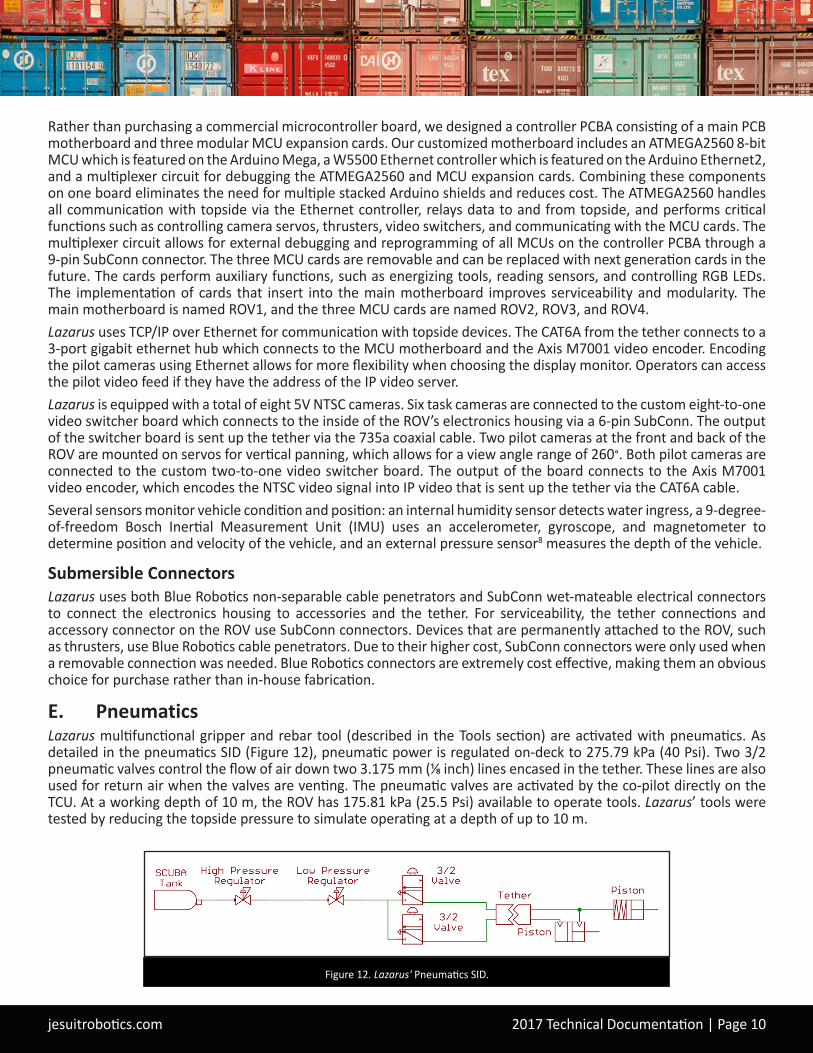
E. PneumaticsLazarus multifunctional gripper and rebar tool (described in the Tools section) are activated with pneumatics. As detailed in the pneumatics SID (Figure 12), pneumatic power is regulated on-deck to 275.79 kPa (40 Psi). Two 3/2 pneumatic valves control the flow of air down two 3.175 mm (⅛ inch) lines encased in the tether. These lines are also used for return air when the valves are venting. The pneumatic valves are activated by the co-pilot directly on the TCU. At a working depth of 10 m, the ROV has 175.81 kPa (25.5 Psi) available to operate tools. Lazarus’ tools were tested by reducing the topside pressure to simulate operating at a depth of up to 10 m.
Figure 12. Lazarus' Pneumatics SID.
jesuitrobotics.com 2017 Technical Documentation | Page 11
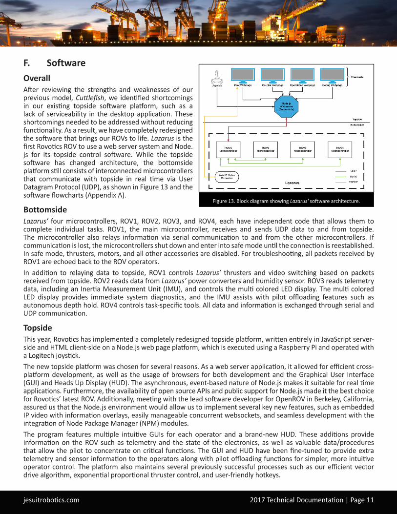
F. SoftwareOverallAfter reviewing the strengths and weaknesses of our previous model, Cuttlefish, we identified shortcomings in our existing topside software platform, such as a lack of serviceability in the desktop application. These shortcomings needed to be addressed without reducing functionality. As a result, we have completely redesigned the software that brings our ROVs to life. Lazarus is the first Rovotics ROV to use a web server system and Node.js for its topside control software. While the topside software has changed architecture, the bottomside platform still consists of interconnected microcontrollers that communicate with topside in real time via User Datagram Protocol (UDP), as shown in Figure 13 and the software flowcharts (Appendix A).
BottomsideLazarus’ four microcontrollers, ROV1, ROV2, ROV3, and ROV4, each have independent code that allows them to complete individual tasks. ROV1, the main microcontroller, receives and sends UDP data to and from topside. The microcontroller also relays information via serial communication to and from the other microcontrollers. If communication is lost, the microcontrollers shut down and enter into safe mode until the connection is reestablished. In safe mode, thrusters, motors, and all other accessories are disabled. For troubleshooting, all packets received by ROV1 are echoed back to the ROV operators. In addition to relaying data to topside, ROV1 controls Lazarus’ thrusters and video switching based on packets received from topside. ROV2 reads data from Lazarus’ power converters and humidity sensor. ROV3 reads telemetry data, including an Inertia Measurement Unit (IMU), and controls the multi colored LED display. The multi colored LED display provides immediate system diagnostics, and the IMU assists with pilot offloading features such as autonomous depth hold. ROV4 controls task-specific tools. All data and information is exchanged through serial and UDP communication.
TopsideThis year, Rovotics has implemented a completely redesigned topside platform, written entirely in JavaScript server-side and HTML client-side on a Node.js web page platform, which is executed using a Raspberry Pi and operated with a Logitech joystick.The new topside platform was chosen for several reasons. As a web server application, it allowed for efficient cross-platform development, as well as the usage of browsers for both development and the Graphical User Interface (GUI) and Heads Up Display (HUD). The asynchronous, event-based nature of Node.js makes it suitable for real time applications. Furthermore, the availability of open source APIs and public support for Node.js made it the best choice for Rovotics’ latest ROV. Additionally, meeting with the lead software developer for OpenROV in Berkeley, California, assured us that the Node.js environment would allow us to implement several key new features, such as embedded IP video with information overlays, easily manageable concurrent websockets, and seamless development with the integration of Node Package Manager (NPM) modules.The program features multiple intuitive GUIs for each operator and a brand-new HUD. These additions provide information on the ROV such as telemetry and the state of the electronics, as well as valuable data/procedures that allow the pilot to concentrate on critical functions. The GUI and HUD have been fine-tuned to provide extra telemetry and sensor information to the operators along with pilot offloading functions for simpler, more intuitive operator control. The platform also maintains several previously successful processes such as our efficient vector drive algorithm, exponential proportional thruster control, and user-friendly hotkeys.
Figure 13. Block diagram showing Lazarus' software architecture.
jesuitrobotics.com 2017 Technical Documentation | Page 12
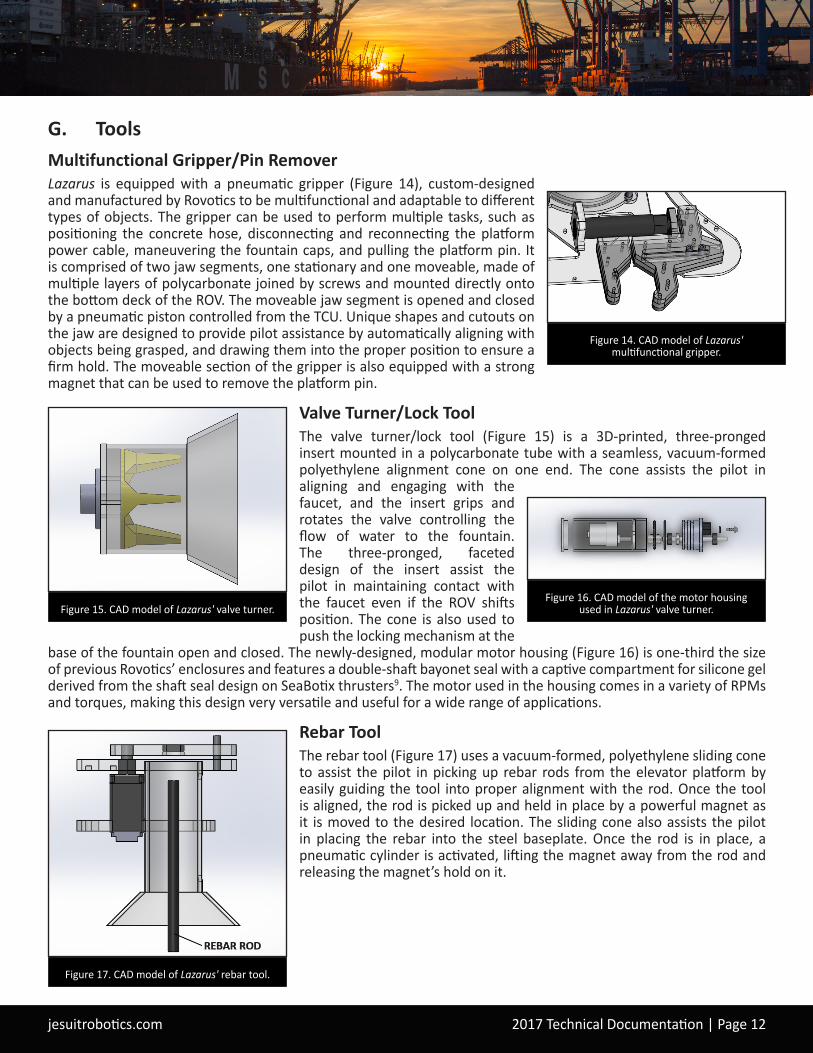
G. ToolsMultifunctional Gripper/Pin RemoverLazarus is equipped with a pneumatic gripper (Figure 14), custom-designed and manufactured by Rovotics to be multifunctional and adaptable to different types of objects. The gripper can be used to perform multiple tasks, such as positioning the concrete hose, disconnecting and reconnecting the platform power cable, maneuvering the fountain caps, and pulling the platform pin. It is comprised of two jaw segments, one stationary and one moveable, made of multiple layers of polycarbonate joined by screws and mounted directly onto the bottom deck of the ROV. The moveable jaw segment is opened and closed by a pneumatic piston controlled from the TCU. Unique shapes and cutouts on the jaw are designed to provide pilot assistance by automatically aligning with objects being grasped, and drawing them into the proper position to ensure a firm hold. The moveable section of the gripper is also equipped with a strong magnet that can be used to remove the platform pin.
Valve Turner/Lock ToolThe valve turner/lock tool (Figure 15) is a 3D-printed, three-pronged insert mounted in a polycarbonate tube with a seamless, vacuum-formed polyethylene alignment cone on one end. The cone assists the pilot in aligning and engaging with the faucet, and the insert grips and rotates the valve controlling the flow of water to the fountain. The three-pronged, faceted design of the insert assist the pilot in maintaining contact with the faucet even if the ROV shifts position. The cone is also used to push the locking mechanism at the
base of the fountain open and closed. The newly-designed, modular motor housing (Figure 16) is one-third the size of previous Rovotics’ enclosures and features a double-shaft bayonet seal with a captive compartment for silicone gel derived from the shaft seal design on SeaBotix thrusters9. The motor used in the housing comes in a variety of RPMs and torques, making this design very versatile and useful for a wide range of applications.
Rebar ToolThe rebar tool (Figure 17) uses a vacuum-formed, polyethylene sliding cone to assist the pilot in picking up rebar rods from the elevator platform by easily guiding the tool into proper alignment with the rod. Once the tool is aligned, the rod is picked up and held in place by a powerful magnet as it is moved to the desired location. The sliding cone also assists the pilot in placing the rebar into the steel baseplate. Once the rod is in place, a pneumatic cylinder is activated, lifting the magnet away from the rod and releasing the magnet’s hold on it.
Figure 14. CAD model of Lazarus' multifunctional gripper.
Figure 15. CAD model of Lazarus' valve turner.
Figure 17. CAD model of Lazarus' rebar tool.
Figure 16. CAD model of the motor housing used in Lazarus' valve turner.
jesuitrobotics.com 2017 Technical Documentation | Page 13
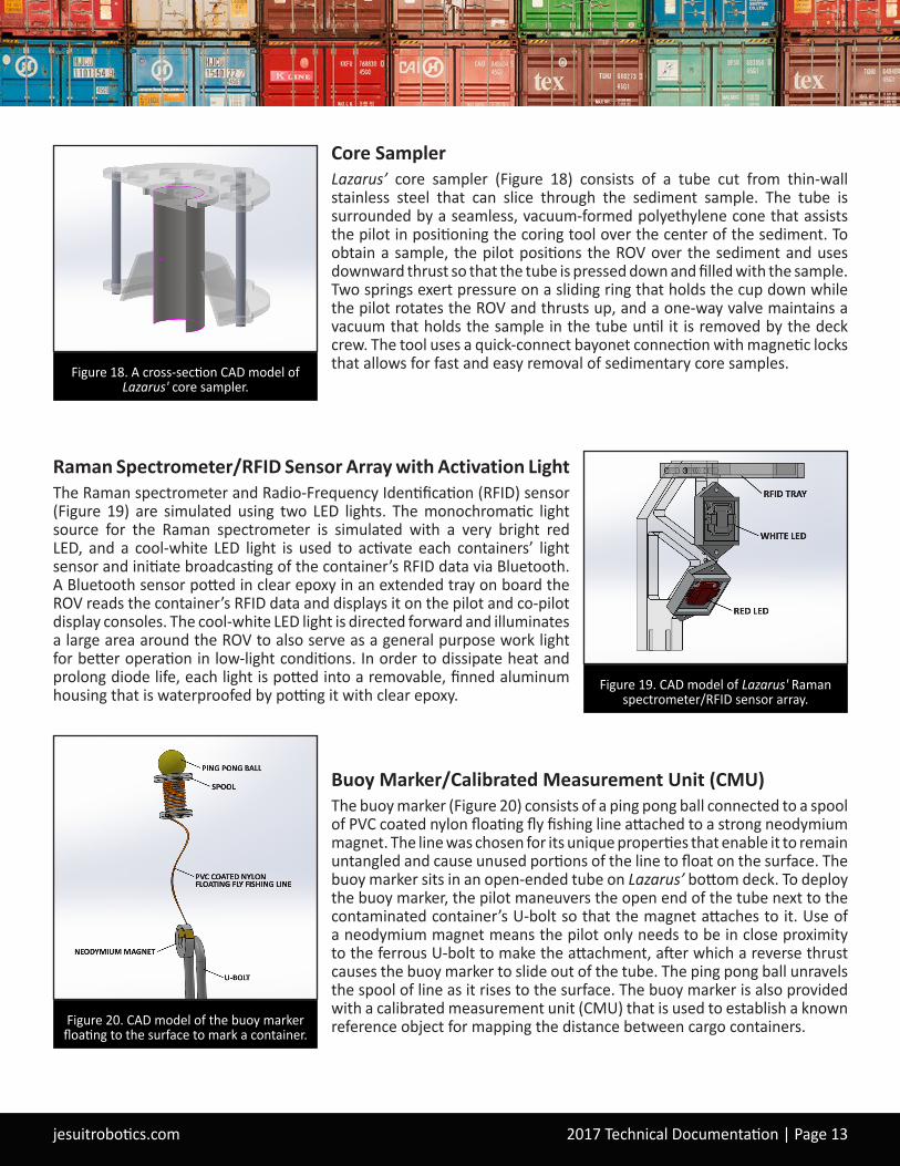
Core SamplerLazarus’ core sampler (Figure 18) consists of a tube cut from thin-wall stainless steel that can slice through the sediment sample. The tube is surrounded by a seamless, vacuum-formed polyethylene cone that assists the pilot in positioning the coring tool over the center of the sediment. To obtain a sample, the pilot positions the ROV over the sediment and uses downward thrust so that the tube is pressed down and filled with the sample. Two springs exert pressure on a sliding ring that holds the cup down while the pilot rotates the ROV and thrusts up, and a one-way valve maintains a vacuum that holds the sample in the tube until it is removed by the deck crew. The tool uses a quick-connect bayonet connection with magnetic locks that allows for fast and easy removal of sedimentary core samples.
Raman Spectrometer/RFID Sensor Array with Activation LightThe Raman spectrometer and Radio-Frequency Identification (RFID) sensor (Figure 19) are simulated using two LED lights. The monochromatic light source for the Raman spectrometer is simulated with a very bright red LED, and a cool-white LED light is used to activate each containers’ light sensor and initiate broadcasting of the container’s RFID data via Bluetooth. A Bluetooth sensor potted in clear epoxy in an extended tray on board the ROV reads the container’s RFID data and displays it on the pilot and co-pilot display consoles. The cool-white LED light is directed forward and illuminates a large area around the ROV to also serve as a general purpose work light for better operation in low-light conditions. In order to dissipate heat and prolong diode life, each light is potted into a removable, finned aluminum housing that is waterproofed by potting it with clear epoxy.
Buoy Marker/Calibrated Measurement Unit (CMU)The buoy marker (Figure 20) consists of a ping pong ball connected to a spool of PVC coated nylon floating fly fishing line attached to a strong neodymium magnet. The line was chosen for its unique properties that enable it to remain untangled and cause unused portions of the line to float on the surface. The buoy marker sits in an open-ended tube on Lazarus’ bottom deck. To deploy the buoy marker, the pilot maneuvers the open end of the tube next to the contaminated container’s U-bolt so that the magnet attaches to it. Use of a neodymium magnet means the pilot only needs to be in close proximity to the ferrous U-bolt to make the attachment, after which a reverse thrust causes the buoy marker to slide out of the tube. The ping pong ball unravels the spool of line as it rises to the surface. The buoy marker is also provided with a calibrated measurement unit (CMU) that is used to establish a known reference object for mapping the distance between cargo containers.
Figure 19. CAD model of Lazarus' Raman spectrometer/RFID sensor array.
Figure 18. A cross-section CAD model of Lazarus' core sampler.
Figure 20. CAD model of the buoy marker floating to the surface to mark a container.

jesuitrobotics.com 2017 Technical Documentation | Page 14
PixelStick SoftwareUnderwater distance measurements can be determined by scaling screenshots of underwater objects using PixelStick7 software. Using a screen shot, a pixel measurement is taken of an object with known dimensions, and a pixel measurement of an object with unknown dimensions can be quickly determined using an algebraic formula. To calculate the distances between cargo containers, the CMU on the buoy marker serves as the known dimension. For example, calculating a container distance by using the known size object:
325 pixels (buoy) 75 cm (buoy known) = 1275 pixels (distance between containers) x cm (unknown distance between containers) 1275 pixels x 75 cm 325 pixels = 294.23 cm distance between containers
HarvesterLazarus’ harvester (Figure 21) consists of a polycarbonate frame mounted on the side of the ROV. Flexible teeth are connected to the frame on one side and left unattached on the other, allowing objects, such as clams or beacons, to pass through the teeth when the tool is pressed down over them. The frame is chamfered to help guide objects through the teeth, and a netting is attached to the top of the frame to contain harvested objects until the ROV surfaces.
Neopixel RGB LED Status Lights Lazarus' electronics housing is lined with an array of multi-colored, individually-addressable neopixel RGB LEDs (Figure 22) that displays pre-programmed light patterns which change upon startup and during critical periods such as operation mode, safe-for-handling mode, and communications lost mode. The patterns serve as quick visual indicators of Lazarus’ operational status to the deck crew and operators to ensure safe handling. For example, red lights indicate loss of communication, green lights indicate that the ROV is safe to handle, blue lights indicate that the ROV is booting up, and white lights indicate that the ROV is operating.
Camera SystemsLazarus is equipped with two pilot tilt cameras housed in the front and back camera portals. Six 170° wide-angle task cameras are also strategically placed around the ROV to ensure maximum visibility and efficiency when performing tasks. Each pilot camera can be rotated 90° with a servo attached to the camera’s 3D printed camera mount, giving the pilot 260° visibility range. The task camera mounts are placed to provide optimal angles of view during tasks, providing an ideal pilot perspective of the tool and the objective simultaneously in the same frame of view (Figure 23). Our potted task camera enclosures are derived from the potted camera design used on the Red October ROV2, which we saw when we met its designers during a company tour at the OpenROV facility in Berkeley, California. This allowed us to move away from the complexity of waterproof seals and further reduce the size of our task cameras.
Figure 21. Lazarus' harvester picking up clams from a contaminated area.
Figure 22. A segment of the neopixel RGB LED status lights that line the interior of
the electronics housing. Green lights indicate that Lazarus is safe to handle.
Figure 23. The pilot perspective monitor view showing the valve turner and the fountain platform in the same frame.

jesuitrobotics.com 2017 Technical Documentation | Page 15
H. Product DemonstrationTask 1 - Commerce: Hyperloop ConstructionThe pilot uses the rebar tool to insert two rebar rods into position in the steel baseplate. Once the rods are in place, a member of the deck crew lowers the frame for the concrete onto the baseplate guided by video from the ROV’s cameras. Once the frame is in place, the pilot removes the platform pin using the magnet mounted on the gripper (Figure 24), then uses the gripper again to pick up the concrete hose, transport it to the frame, and position it for pouring concrete into the frame. Finally, the harvester is used to collect three beacons and hold them for return to the surface.
Task 2 - Entertainment: Light and Water Show MaintenanceThe pilot disconnects the fountain power cable by pulling it out of the connector using the gripper and reverse thrust. The valve turner/lock tool is used to turn the faucet and stop water flow to the fountain. The pilot then maneuvers the ROV into the fountain interior where the valve turner/lock tool is used to disengage the locking mechanism at the base of the fountain. Next the pilot maneuvers to the topside of the fountain and uses the gripper to remove the old fountain cap from the fountain (Figure 25) and install the new fountain cap. The pilot then maneuvers back into the fountain interior and re-engages the locking mechanism with the valve turner/lock tool. The pilot moves out of the fountain and turns the faucet back on using the valve turner/lock tool. The power cable is reconnected using the gripper. Finally, the gripper is used to return the old fountain to the surface, side of the pool.
Task 3 - Health: Environmental CleanupTo determine if any contaminants are present in the selected areas, the pilot illuminates them using the Raman spectrometer, then the deck crew performs analysis of the Raman spectra to determine which area is contaminated. The pilot then uses the harvester to retrieve two clams from the contaminated area and returns them to the surface. The core sampler is then used to collect a sediment sample from the contaminated area and return it to the surface. Finally, the gripper is used to grasp the cap and place it over the contaminated area (Figure 26).
Task 4 - Safety: Risk MitigationThe pilot uses Lazarus’ camera system to locate the four cargo containers. The white RFID activation light is then used to activate each container’s RFID (Figure 27). The RFID information is obtained via Bluetooth, and the operations manager uses the container’s identification number to determine its contents and decide if they are high risk. Once all of the containers have been identified, the pilot maneuvers the ROV to attach the buoy marker to the U-bolt of the highest risk cargo container. The operations manager uses PixelStick software to determine the direction and distance of the highest risk container to the other three containers, then uses that data to make a survey map of the site.
Figure 25. Lazarus using the gripper to remove the old fountain cap.
Figure 27. Lazurus using the white activation light to activate the RFID on a
container.
Figure 24. Lazarus pulling the platform pin using the magnet on the gripper.
Figure 26. Lazarus using the gripper to place the cap over the contaminated area.
jesuitrobotics.com 2017 Technical Documentation | Page 16
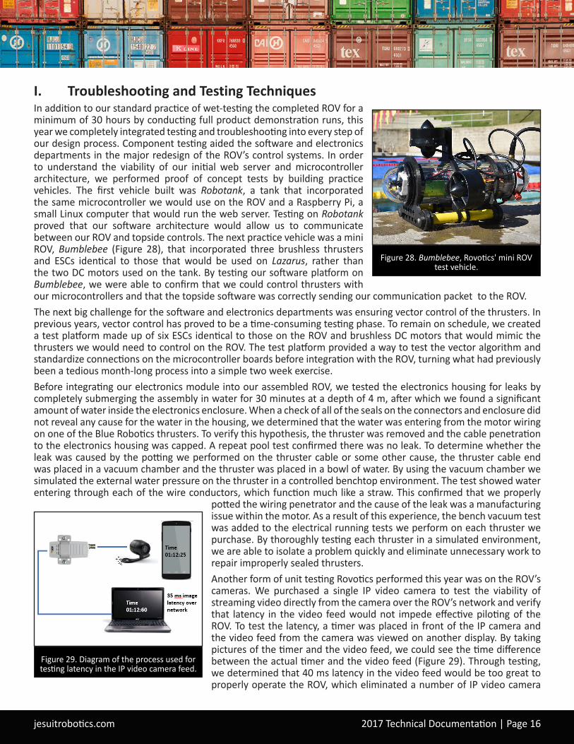
I. Troubleshooting and Testing TechniquesIn addition to our standard practice of wet-testing the completed ROV for a minimum of 30 hours by conducting full product demonstration runs, this year we completely integrated testing and troubleshooting into every step of our design process. Component testing aided the software and electronics departments in the major redesign of the ROV’s control systems. In order to understand the viability of our initial web server and microcontroller architecture, we performed proof of concept tests by building practice vehicles. The first vehicle built was Robotank, a tank that incorporated the same microcontroller we would use on the ROV and a Raspberry Pi, a small Linux computer that would run the web server. Testing on Robotank proved that our software architecture would allow us to communicate between our ROV and topside controls. The next practice vehicle was a mini ROV, Bumblebee (Figure 28), that incorporated three brushless thrusters and ESCs identical to those that would be used on Lazarus, rather than the two DC motors used on the tank. By testing our software platform on Bumblebee, we were able to confirm that we could control thrusters with our microcontrollers and that the topside software was correctly sending our communication packet to the ROV. The next big challenge for the software and electronics departments was ensuring vector control of the thrusters. In previous years, vector control has proved to be a time-consuming testing phase. To remain on schedule, we created a test platform made up of six ESCs identical to those on the ROV and brushless DC motors that would mimic the thrusters we would need to control on the ROV. The test platform provided a way to test the vector algorithm and standardize connections on the microcontroller boards before integration with the ROV, turning what had previously been a tedious month-long process into a simple two week exercise. Before integrating our electronics module into our assembled ROV, we tested the electronics housing for leaks by completely submerging the assembly in water for 30 minutes at a depth of 4 m, after which we found a significant amount of water inside the electronics enclosure. When a check of all of the seals on the connectors and enclosure did not reveal any cause for the water in the housing, we determined that the water was entering from the motor wiring on one of the Blue Robotics thrusters. To verify this hypothesis, the thruster was removed and the cable penetration to the electronics housing was capped. A repeat pool test confirmed there was no leak. To determine whether the leak was caused by the potting we performed on the thruster cable or some other cause, the thruster cable end was placed in a vacuum chamber and the thruster was placed in a bowl of water. By using the vacuum chamber we simulated the external water pressure on the thruster in a controlled benchtop environment. The test showed water entering through each of the wire conductors, which function much like a straw. This confirmed that we properly
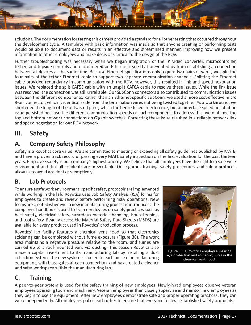
potted the wiring penetrator and the cause of the leak was a manufacturing issue within the motor. As a result of this experience, the bench vacuum test was added to the electrical running tests we perform on each thruster we purchase. By thoroughly testing each thruster in a simulated environment, we are able to isolate a problem quickly and eliminate unnecessary work to repair improperly sealed thrusters.Another form of unit testing Rovotics performed this year was on the ROV’s cameras. We purchased a single IP video camera to test the viability of streaming video directly from the camera over the ROV’s network and verify that latency in the video feed would not impede effective piloting of the ROV. To test the latency, a timer was placed in front of the IP camera and the video feed from the camera was viewed on another display. By taking pictures of the timer and the video feed, we could see the time difference between the actual timer and the video feed (Figure 29). Through testing, we determined that 40 ms latency in the video feed would be too great to properly operate the ROV, which eliminated a number of IP video camera
Figure 29. Diagram of the process used for testing latency in the IP video camera feed.
Figure 28. Bumblebee, Rovotics' mini ROV test vehicle.
jesuitrobotics.com 2017 Technical Documentation | Page 17
solutions. The documentation for testing this camera provided a standard for all other testing that occurred throughout the development cycle. A template with basic information was made so that anyone creating or performing tests would be able to document data or results in an effective and streamlined manner, improving how we present information to other employees and make decisions critical to the design of the ROV. Further troubleshooting was necessary when we began integration of the IP video converter, microcontroller, tether, and topside controls and encountered an Ethernet issue that prevented us from establishing a connection between all devices at the same time. Because Ethernet specifications only require two pairs of wires, we split the four pairs of the tether Ethernet cable to support two separate communication channels. Splitting the Ethernet cable provided redundancy in communication with the ROV, however, this resulted in link and speed negotiation issues. We replaced the split CAT5E cable with an unsplit CAT6A cable to resolve these issues. While the link issue was resolved, the connection was still unreliable. Our SubConn connectors also contributed to communication issues between the different components. Rather than an Ethernet-specific SubConn, we used a more cost-effective micro 9-pin connector, which is identical aside from the termination wires not being twisted together. As a workaround, we shortened the length of the untwisted pairs, which further reduced interference, but an interface speed negotiation issue persisted because the different communication speeds of each component. To address this, we matched the top and bottom network connections on Gigabit switches. Correcting these issue resulted in a reliable network link and speed negotiation for our ROV network.
III. SafetyA. Company Safety PhilosophySafety is a Rovotics core value. We are committed to meeting or exceeding all safety guidelines published by MATE, and have a proven track record of passing every MATE safety inspection on the first evaluation for the past thirteen years. Employee safety is our company’s highest priority. We believe that all employees have the right to a safe work environment and that all accidents are preventable. Our rigorous training, safety procedures, and safety protocols allow us to avoid accidents preemptively.
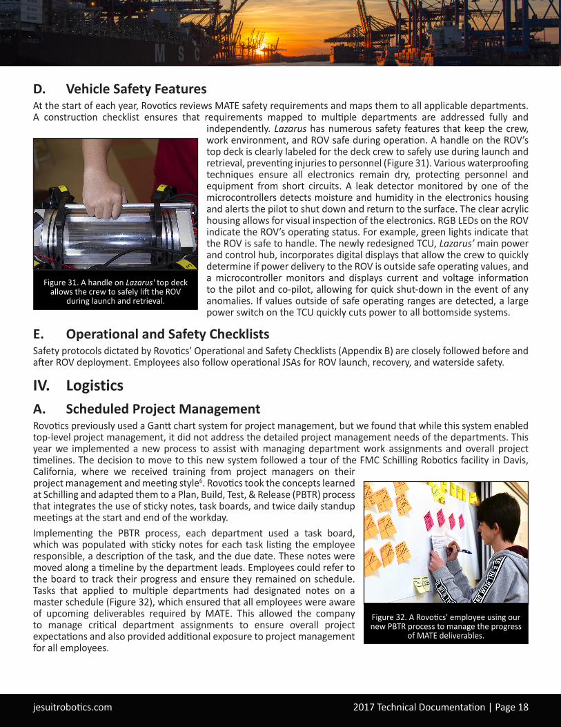
B. Lab ProtocolsTo ensure a safe work environment, specific safety protocols are implemented while working in the lab. Rovotics uses Job Safety Analysis (JSA) forms for employees to create and review before performing risky operations. New forms are created whenever a new manufacturing process is introduced. The company’s handbook is used to train employees on safety practices such as back safety, electrical safety, hazardous materials handling, housekeeping, and tool safety. Readily accessible Material Safety Data Sheets (MSDS) are available for every product used in Rovotics’ production process.Rovotics’ lab facility features a chemical vent hood so that electronics soldering can be completed without fume exposure (Figure 30). The work area maintains a negative pressure relative to the room, and fumes are carried up to a roof-mounted vent via ducting. This season Rovotics also made a capital investment to its manufacturing lab by installing a dust collection system. The new system is ducted to each piece of manufacturing equipment, with blast gates at each connection, and has created a cleaner and safer workspace within the manufacturing lab.
C. TrainingA peer-to-peer system is used for the safety training of new employees. Newly-hired employees observe veteran employees operating tools and machinery. Veteran employees then closely supervise and mentor new employees as they begin to use the equipment. After new employees demonstrate safe and proper operating practices, they can work independently. All employees police each other to ensure that everyone follows established safety protocols.
Figure 30. A Rovotics employee wearing eye protection and soldering wires in the
chemical vent hood.
jesuitrobotics.com 2017 Technical Documentation | Page 18
D. Vehicle Safety FeaturesAt the start of each year, Rovotics reviews MATE safety requirements and maps them to all applicable departments. A construction checklist ensures that requirements mapped to multiple departments are addressed fully and
independently. Lazarus has numerous safety features that keep the crew, work environment, and ROV safe during operation. A handle on the ROV’s top deck is clearly labeled for the deck crew to safely use during launch and retrieval, preventing injuries to personnel (Figure 31). Various waterproofing techniques ensure all electronics remain dry, protecting personnel and equipment from short circuits. A leak detector monitored by one of the microcontrollers detects moisture and humidity in the electronics housing and alerts the pilot to shut down and return to the surface. The clear acrylic housing allows for visual inspection of the electronics. RGB LEDs on the ROV indicate the ROV’s operating status. For example, green lights indicate that the ROV is safe to handle. The newly redesigned TCU, Lazarus’ main power and control hub, incorporates digital displays that allow the crew to quickly determine if power delivery to the ROV is outside safe operating values, and a microcontroller monitors and displays current and voltage information to the pilot and co-pilot, allowing for quick shut-down in the event of any anomalies. If values outside of safe operating ranges are detected, a large power switch on the TCU quickly cuts power to all bottomside systems.
E. Operational and Safety ChecklistsSafety protocols dictated by Rovotics’ Operational and Safety Checklists (Appendix B) are closely followed before and after ROV deployment. Employees also follow operational JSAs for ROV launch, recovery, and waterside safety.
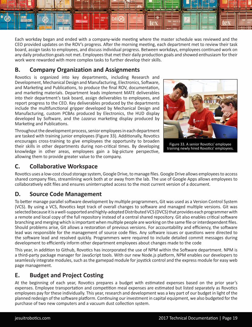
IV. LogisticsA. Scheduled Project Management Rovotics previously used a Gantt chart system for project management, but we found that while this system enabled top-level project management, it did not address the detailed project management needs of the departments. This year we implemented a new process to assist with managing department work assignments and overall project timelines. The decision to move to this new system followed a tour of the FMC Schilling Robotics facility in Davis, California, where we received training from project managers on their project management and meeting style6. Rovotics took the concepts learned at Schilling and adapted them to a Plan, Build, Test, & Release (PBTR) process that integrates the use of sticky notes, task boards, and twice daily standup meetings at the start and end of the workday.Implementing the PBTR process, each department used a task board, which was populated with sticky notes for each task listing the employee responsible, a description of the task, and the due date. These notes were moved along a timeline by the department leads. Employees could refer to the board to track their progress and ensure they remained on schedule. Tasks that applied to multiple departments had designated notes on a master schedule (Figure 32), which ensured that all employees were aware of upcoming deliverables required by MATE. This allowed the company to manage critical department assignments to ensure overall project expectations and also provided additional exposure to project management for all employees.
Figure 31. A handle on Lazarus' top deck allows the crew to safely lift the ROV
during launch and retrieval.
Figure 32. A Rovotics' employee using our new PBTR process to manage the progress
of MATE deliverables.
jesuitrobotics.com 2017 Technical Documentation | Page 19
Each workday began and ended with a company-wide meeting where the master schedule was reviewed and the CEO provided updates on the ROV’s progress. After the morning meeting, each department met to review their task board, assign tasks to employees, and discuss individual progress. Between workdays, employees continued work on any daily production goals not met. Employees that met their daily production goals and showed enthusiasm for their work were rewarded with more complex tasks to further develop their skills.
B. Company Organization and AssignmentsRovotics is organized into key departments, including Research and Development, Mechanical Design and Manufacturing, Electronics, Software, and Marketing and Publications, to produce the final ROV, documentation, and marketing materials. Department leads implement MATE deliverables into their department’s task board, assign deliverables to employees, and report progress to the CEO. Key deliverables produced by the departments include the multifunctional gripper developed by Mechanical Design and Manufacturing, custom PCBAs produced by Electronics, the HUD display developed by Software, and the Lazarus marketing display produced by Marketing and Publications.Throughout the development process, senior employees in each department are tasked with training junior employees (Figure 33). Additionally, Rovotics encourages cross-training to give employees the opportunity to broaden their skills in other departments during non-critical times. By developing knowledge in other areas, employees gain a big-picture perspective, allowing them to provide greater value to the company.
C. Collaborative WorkspaceRovotics uses a low-cost cloud storage system, Google Drive, to manage files. Google Drive allows employees to access shared company files, streamlining work both at or away from the lab. The use of Google Apps allows employees to collaboratively edit files and ensures uninterrupted access to the most current version of a document.
D. Source Code ManagementTo better manage parallel software development by multiple programmers, Git was used as a Version Control System (VCS). By using a VCS, Rovotics kept track of overall changes to software and managed multiple versions. Git was selected because it is a well-supported and highly-adopted Distributed VCS (DVCS) that provides each programmer with a remote and local copy of the full repository instead of a central shared repository. Git also enables critical software branching and merging which is important when multiple people are working on the same file or interdependent files. Should problems arise, Git allows a restoration of previous versions. For accountability and efficiency, the software lead was responsible for the management of source code files. Any software issues or questions were directed to the software lead and resolved quickly. Programmers were required to include detailed commit messages during development to efficiently inform other department employees about changes made to the codeThis year, in addition to Github, Rovotics has incorporated the use of NPM within the Software department. NPM is a third-party package manager for JavaScript tools. With our new Node.js platform, NPM enables our developers to seamlessly integrate modules, such as the gamepad module for joystick control and the express module for easy web page management.
E. Budget and Project CostingAt the beginning of each year, Rovotics prepares a budget with estimated expenses based on the prior year’s expenses. Employee transportation and competition meal expenses are estimated but listed separately as Rovotics employees pay for these individually. This year, research and development was a key part of our budget in light of the planned redesign of the software platform. Continuing our investment in capital equipment, we also budgeted for the purchase of two new computers and a vacuum dust collection system.
Figure 33. A senior Rovotics' employee training newly hired Rovotics' employees.
jesuitrobotics.com 2017 Technical Documentation | Page 20
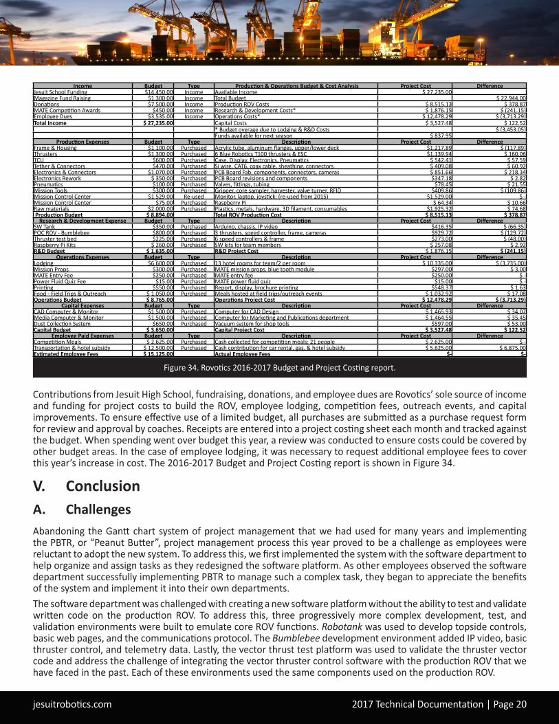
Contributions from Jesuit High School, fundraising, donations, and employee dues are Rovotics’ sole source of income and funding for project costs to build the ROV, employee lodging, competition fees, outreach events, and capital improvements. To ensure effective use of a limited budget, all purchases are submitted as a purchase request form for review and approval by coaches. Receipts are entered into a project costing sheet each month and tracked against the budget. When spending went over budget this year, a review was conducted to ensure costs could be covered by other budget areas. In the case of employee lodging, it was necessary to request additional employee fees to cover this year’s increase in cost. The 2016-2017 Budget and Project Costing report is shown in Figure 34.
V. ConclusionA. ChallengesAbandoning the Gantt chart system of project management that we had used for many years and implementing the PBTR, or “Peanut Butter”, project management process this year proved to be a challenge as employees were reluctant to adopt the new system. To address this, we first implemented the system with the software department to help organize and assign tasks as they redesigned the software platform. As other employees observed the software department successfully implementing PBTR to manage such a complex task, they began to appreciate the benefits of the system and implement it into their own departments. The software department was challenged with creating a new software platform without the ability to test and validate written code on the production ROV. To address this, three progressively more complex development, test, and validation environments were built to emulate core ROV functions. Robotank was used to develop topside controls, basic web pages, and the communications protocol. The Bumblebee development environment added IP video, basic thruster control, and telemetry data. Lastly, the vector thrust test platform was used to validate the thruster vector code and address the challenge of integrating the vector thruster control software with the production ROV that we have faced in the past. Each of these environments used the same components used on the production ROV.
Figure 34. Rovotics 2016-2017 Budget and Project Costing report.
Income Budget Type Production & Operations Budget & Cost Analysis Project Cost Difference Jesuit School Funding $14,450.00 Income Available Income $ 27,235.00 Magazine Fund Raising $1,300.00 Income Total Budget $ 22,944.00 Donations $7,500.00 Income Production ROV Costs $ 8,515.13 $ 378.87 MATE Competition Awards $450.00 Income Research & Development Costs* $ 1,876.15 $ (241.15) Employee Dues $3,535.00 Income Operations Costs* $ 12,478.29 $ (3,713.29) Total Income $ 27,235.00 Capital Costs $ 3,527.48 $ 122.52
* Budget overage due to Lodging & R&D Costs $ (3,453.05) Funds available for next season $ 837.95
Production Expenses Budget Type Description Project Cost Difference Frame & Housing $1,100.00 Purchased Acrylic tube, aluminum flanges, upper/lower deck $1,217.89 $ (117.89) Thrusters $1,300.00 Purchased 6 Blue Robotics T100 thrusters & ESC $1,139.94 $ 160.06 TCU $600.00 Purchased Case, Display, Electronics, Pneumatics $ 542.41 $ 57.59 Tether & Connectors $470.00 Purchased Si wire, CAT6, coax cable, sheathing, connectors $ 409.08 $ 60.92 Electronics & Connectors $1,070.00 Purchased PCB Board Fab, components, connectors, cameras $ 851.66 $ 218.34 Electronics Rework $ 350.00 Purchased PCB Board revisions and components $347.18 $ 2.82 Pneumatics $100.00 Purchased Valves, fittings, tubing $78.45 $ 21.55 Mission Tools $300.00 Purchased Gripper, core sampler, harvester, valve turner, RFID $409.86 $ (109.86) Mission Control Center $1,529.00 Re-used Monitor, laptop, joystick; (re-used from 2015) $1,529.00 $ - Mission Control Center $75.00 Purchased Raspberry Pi $ 64.34 $ 10.66 Raw materials $2,000.00 Purchased Plastics, metals, hardware, 3D filament, consumables $1,925.32 $ 74.68 Production Budget $ 8,894.00 Total ROV Production Cost $ 8,515.13 $ 378.87
Research & Development Expense Budget Type Description Project Cost Difference SW Tank $350.00 Purchased Arduino, chassis, IP video $416.35 $ (66.35) POC ROV - Bumblebee $800.00 Purchased 3 thrusters, speed controller, frame, cameras $929.72 $ (129.72) Thruster test bed $225.00 Purchased 6 speed controllers & frame $273.00 $ (48.00) Raspberry Pi Kits $ 260.00 Purchased SW kits for team members $ 257.08 $ 2.92 R&D Budget $ 1,635.00 R&D Project Cost $ 1,876.15 $ (241.15)
Operations Expenses Budget Type Description Project Cost Difference Lodging $6,600.00 Purchased 13 hotel rooms for team/2 per room $ 10,335.00 $ (3,735.00) Mission Props $300.00 Purchased MATE mission props, blue tooth module $297.00 $ 3.00 MATE Entry Fee $250.00 Purchased MATE entry fee $250.00 $ - Power Fluid Quiz Fee $15.00 Purchased MATE power fluid quiz $15.00 $ - Printing $550.00 Purchased Report, display, brochure printing $548.37 $ 1.63 Food - Field Trips & Outreach $ 1,050.00 Purchased Meals hosted at field trips/outreach events $ 1,032.92 $ 17.08 Operations Budget $ 8,765.00 Operations Project Cost $ 12,478.29 $ (3,713.29)
Capital Expenses Budget Type Description Project Cost Difference CAD Computer & Monitor $1,500.00 Purchased Computer for CAD Design $ 1,465.93 $ 34.07 Media Computer & Monitor $1,500.00 Purchased Computer for Marketing and Publications department $ 1,464.55 $ 35.45 Dust Collection System $650.00 Purchased Vacuum system for shop tools $597.00 $ 53.00 Capital Budget $ 3,650.00 Capital Project Cost $ 3,527.48 $ 122.52
Employee Paid Expenses Budget Type Description Project Cost Difference Competition Meals $ 2,625.00 Purchased Cash collected for competition meals; 21 people $ 2,625.00 $ - Transportation & hotel subsidy $ 12,500.00 Purchased Cash contribution for car rental, gas, & hotel subsidy $ 5,625.00 $ 6,875.00 Estimated Employee Fees $ 15,125.00 Actual Employee Fees $- $-
jesuitrobotics.com 2017 Technical Documentation | Page 21
B. Lessons Learned and Skills GainedThis year, Rovotics learned valuable technical lessons from the numerous troubleshooting scenarios we encountered, as described in the Troubleshooting and Testing Techniques section. We also learned important management lessons from implementing our new PBTR project management process. Throughout the year, each department worked very well with their individual project schedules. Failure to pay close attention to interdependencies between these schedules, however, resulted in numerous production delays. As a result, Rovotics learned the importance of interdepartmental dependencies and plans to improve alignment of project schedules and interdependencies between departments in the future.Training is a critical aspect of employee skill development at Rovotics. This year we worked with OpenROV software engineers early on to explore software platform improvements using Node.js. This allowed us to establish a new platform architecture that provided a more serviceable code base. In addition to regular industry field trips to companies like FMC Schilling Robotics and OpenROV, we invited professionals to our facility to provide in-depth training for our employees. This year, a Rovotics alumni, now employed as a manufacturing engineer, and a professional machinist were invited to share their expertise in machining and parts fabrication. This greatly improved the quality and efficiency of our CNC and precision-machining.
C. Future ImprovementsLast year’s goals for integrating the IMU into the HUD and implementing HD cameras were successfully met in this year’s ROV. Plans for next year include the continued development by the Electronics department of custom ROV control boards that will increase the versatility of our modular design. Additionally, electronics experienced a high failure rate this year in manufacturing custom boards. After analyzing these failures, we plan on reducing the aperture size of the solder stencils and changing our printed circuit board surface finishes to address the problem. Changing these two production methods will reduce the chance of bridged solder pads. Furthermore, we will be researching methods to reduce our video latency from 35 ms to less than 25 ms. This should reduce the perceivable latency in the video stream. The company as a whole will continue to refine the task board and master scheduling system we implemented this year with the goal of further streamlining and expediting our design and manufacturing process. To that end, we also plan on increasing the number of workdays early in the development cycle in order to identify design parameters and goals sooner and enable each department to begin work on individual components earlier in the design process.
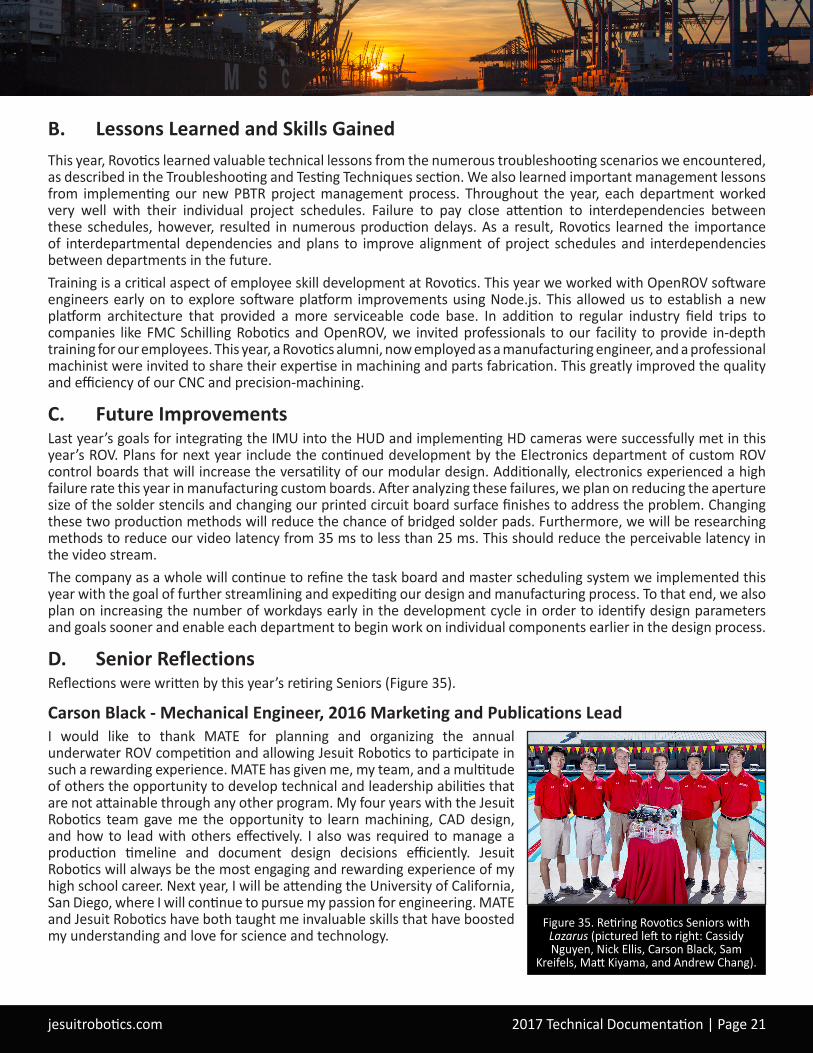
D. Senior ReflectionsReflections were written by this year’s retiring Seniors (Figure 35).
Carson Black - Mechanical Engineer, 2016 Marketing and Publications Lead I would like to thank MATE for planning and organizing the annual underwater ROV competition and allowing Jesuit Robotics to participate in such a rewarding experience. MATE has given me, my team, and a multitude of others the opportunity to develop technical and leadership abilities that are not attainable through any other program. My four years with the Jesuit Robotics team gave me the opportunity to learn machining, CAD design, and how to lead with others effectively. I also was required to manage a production timeline and document design decisions efficiently. Jesuit Robotics will always be the most engaging and rewarding experience of my high school career. Next year, I will be attending the University of California, San Diego, where I will continue to pursue my passion for engineering. MATE and Jesuit Robotics have both taught me invaluable skills that have boosted my understanding and love for science and technology.
Figure 35. Retiring Rovotics Seniors with Lazarus (pictured left to right: Cassidy Nguyen, Nick Ellis, Carson Black, Sam
Kreifels, Matt Kiyama, and Andrew Chang).

jesuitrobotics.com 2017 Technical Documentation | Page 22
Andrew Chang - Electrical Engineer, 2016 and 2017 Electronics Lead, 2017 CEO The opportunities that MATE and Jesuit Robotics have given me over the past three years have been phenomenal. From designing and building complex printed circuit boards to speaking in sales presentations, every experience has given me new skills and knowledge that I can apply to the real world. The friendships that I have gained during my time here are a great blessing in my life, and I will always look back on my experiences with a fondness that reflects the support and solidarity of my teammates. Although it pains me to leave Jesuit Robotics, I am truly grateful for the opportunities that I have been afforded. I am excited and proud to continue the next chapter of my life at the University of California, Berkeley, where I will be studying Electrical Engineering. Finally, I want to thank MATE for organizing and planning such an amazing underwater ROV competition.
Nick Ellis - Mechanical Engineer, 2016 and 2017 Mechanical Design LeadI would like to thank my teammates, coaches, parents, Jesuit High School, and MATE for providing me with the opportunity to grow as a person in my work ethic, confidence, and technical skills. Being able to go to robotics every Saturday to work on ROVs and learn more about technology and communication has not only provided me with a head start for college and a career, but has also given me some of my closest friends. Robotics at Jesuit has been a place where I can truly develop my passion for creativity and using technology to make the world a better place. I’ve learned many skills and lessons including design principles, project management skills, manufacturing techniques, and how to communicate my ideas to a group. I am grateful for the unique experiences I have had in the MATE competition with Jesuit Robotics, and I wouldn’t trade them for the world. I will continue to pursue my passion for engineering at Santa Clara University where I will study Mechanical and Electrical Engineering.
Matthew Kiyama - Software Engineer, 2016 CEO, 2017 Research and Development LeadThrough the MATE competition, I’ve been able to explore my passion for technology and problem solving. The experiences I’ve had on the Jesuit Robotics team have taught me about project management, software development, product development, presentation skills, technical writing, and collaboration. All of these skills have already helped me earn internships and given me a head start on my future as an engineer. I plan to continue my journey by studying Computer Science at Santa Clara University. My time at Jesuit Robotics has helped me not only develop technical skills , but also mature as a person. The lessons I’ve learned and the experiences I’ve shared will stick with me forever, and I can’t wait to share my knowledge with others. Thank you to the MATE center and Jesuit High School for providing such a wonderful opportunity to learn about technology and engineering.
Sam Kreifels - Mechanical Engineer, 2016 and 2017 Manufacturing LeadIn the past four years, I have had the extreme blessing of participating in MATE’s underwater ROV competition through Jesuit High School Robotics. The experience has been one of great learning and fun for me, during which I gained innumerable engineering skills, from CNC manufacturing and CAD design, to professional presentation and organized company workflow. The team effort has defined my high school experience, filling my memories with good times, plenty of late nights, and very hard work. Involvement in the competition has fostered my interest in engineering, and I look forward to an exciting future studying Mechanical Engineering at the University of Portland. A huge sincere Thank-You to everyone at MATE and the Jesuit Robotics Program, who have given me not only an enlightening and formative experience but also a direction to progress in my life.
Cassidy Nguyen - Software Engineer, 2016 and 2017 Software LeadThrough four years with Jesuit Robotics, I have been so fortunate to have the opportunity to participate in the MATE competition. The time that I have dedicated to Jesuit Robotics and the MATE competition has led to the development of technical and leadership skills that I wouldn't have otherwise acquired in a normal classroom setting. I have gained invaluable skills in software design and integration, project management, time management, and technical writing. The hands-on experience gained in my time with Jesuit Robotics has provided me with a deeper insight into engineering, and I hope to pursue that passion in college by double majoring in Neuroscience and Computer Science at Creighton University. I would like to thank MATE for its continued support and for organizing the underwater ROV competition. I would also like to thank Jesuit Robotics for guiding me and supporting me in discovering my passions and aspirations.
jesuitrobotics.com 2017 Technical Documentation | Page 23
E. Acknowledgements • MATE Center and Marine Technology Society - Sponsoring this year’s competition• National Science Foundation - Their funding of the MATE competition Long Beach City College - Hosting this year’s
MATE competition• Oceaneering International - Their support of the MATE competition• Jesuit High School - Generous donation of funding and pool time• Jay Isaacs, Head Coach - His time, creativity, knowledge, and guidance for the past twelve years• Steve Kiyama, Assistant Coach - His time, experience, and guidance for the team• Cheryl Kiyama, Operations Manager - Her time, experience, and management of the team• Jim Claybrook of Weldmasters - Welding services• MacArtney Connectors - Providing connectors at a reduced rate• GitHub - Providing complimentary private code repositories• Travis CI - Providing continuous integration for private GitHub Repositories• TAP Plastics - Donation of stock plastic• SolidWorks - Donation of SolidWorks 3D Software• FMC/Schilling Robotics - Facility tour and project management training• OpenROV - Facility tour and consulting on Node.js programming• Kennedy High School - Assistance with machining large parts• Mentors - Marc Aprea, Heath Charamuga, Doug Ellis, Chris French, Craig Law, Jayanth Pingili,
Dawn Remme, David Weston, Kelly Whitcomb-Weston• Alice Gabbert and the Whitcomb-Weston Family/Weston & Associates Mechanical Engineers, Inc.
- Their generous donations to the team• Our Families - Their continued support and encouragement
F. References1. Blue Robotics. “T100 Thruster Documentation.” Blue Robotics. Blue Robotics, 22 Aug. 2015. Web.
21 May 2016. <http://docs.bluerobotics.com/thrusters/#t100-thruster-specifications>.2. Carterhbond, Kevin_K, Colin_Ho, Brian_Grau, Fe3C, and Jkerfo02. "Red October- MATE Competition ROV." OpenROV
Forums. N.p., 21 Apr. 2016. Web. 22 May 2017. <https://forum.openrov.com/t/red-october-mate-competition-rov/4245>
3. Maxim Integrated Products. High-Speed, Low-Power, Single-Supply Multichannel, Video Multiplexer-Amplifiers. Sunnyvale: Maxim Integrated Products, 2008. Print.
4. Murata Power Solutions, Inc. DRQ-12/50-L48 Series. Mansfield: Murata Power Solutions, 2015. Print.5. Nave, Rod. “Buoyancy.” HyperPhysics. Georgia State University, 9 Aug. 2013. Web. 21 May 2016. <http://hyperphysics.
phy-astr.gsu.edu/hbase/pbuoy.html>.6. "Obeya in the Workplace: An Overview." Graphic Products Info. N.p., 22 Mar. 2017. Web. 22 May 2017. <https://
www.graphicproducts.com/articles/obeya-in-the-workplace-an-overview/>7. "PixelStick." Plumamazingflat280x64.png. N.p., n.d. Web. 22 May 2017. <http://plumamazing.com/mac/pixelstick>8. TE Connectivity. MS5837-30BA Ultra Small Gel Filled Pressure Sensor. Fremont: TE Connectivity, 2015. Print.9. Teledyne SeaBotix. BTD150 AUV/ROV Thruster. San Diego: Teledyne SeaBotix, 2015. Print.
G. Photo Credits• Cover Image: O’Donnell, Skip. Water Texture. Digital Image. www.istockphoto.com. 25 January 2014. Web. 8 March
2017.• Header Image 1: Port Panoramic at Night. Digital Image. www.emirates-business.ae. 3 December 2016. Web. 18
March 2017.• Header Image 2: Low Saturated Photo of Oil Rig During Golden Hour. Digital Image. www.pexels.com. 6 May 2016.
Web. 18 March 2017.• Header Image 3: Containers Stack. Digital Image. www.maritimecyprus.com. 26 April 2016. Web. 18 February 2017.• All Other Images: Jesuit Robotics 2017
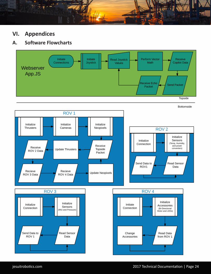
jesuitrobotics.com 2017 Technical Documentation | Page 24
VI. AppendicesA. Software Flowcharts
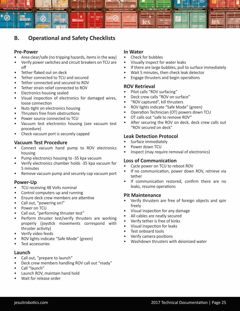
jesuitrobotics.com 2017 Technical Documentation | Page 25
B. Operational and Safety Checklists
Pre-Power• Area clear/safe (no tripping hazards, items in the way)• Verify power switches and circuit breakers on TCU are
off• Tether flaked out on deck• Tether connected to TCU and secured• Tether connected and secured to ROV• Tether strain relief connected to ROV• Electronics housing sealed• Visual inspection of electronics for damaged wires,
loose connection• Nuts tight on electronics housing• Thrusters free from obstructions• Power source connected to TCU• Vacuum test electronics housing (see vacuum test
procedure)• Check vacuum port is securely capped
Vacuum Test Procedure• Connect vacuum hand pump to ROV electronics
housing• Pump electronics housing to -35 kpa vacuum• Verify electronics chamber holds -35 kpa vacuum for
5 minutes• Remove vacuum pump and securely cap vacuum port
Power-Up• TCU receiving 48 Volts nominal• Control computers up and running• Ensure deck crew members are attentive• Call out, “powering on!”• Power on TCU• Call out, “performing thruster test”• Perform thruster test/verify thrusters are working
properly (joystick movements correspond with thruster activity)
• Verify video feeds• ROV lights indicate “Safe Mode” (green)• Test accessories
Launch• Call out, “prepare to launch”• Deck crew members handling ROV call out “ready”• Call “launch”• Launch ROV, maintain hand hold• Wait for release order
In Water• Check for bubbles• Visually inspect for water leaks• If there are large bubbles, pull to surface immediately• Wait 5 minutes, then check leak detector• Engage thrusters and begin operations
ROV Retrieval• Pilot calls “ROV surfacing”• Deck crew calls “ROV on surface”• “ROV captured”, kill thrusters• ROV lights indicate “Safe Mode” (green)• Operation Technician (OT) powers down TCU• OT calls out “safe to remove ROV”• After securing the ROV on deck, deck crew calls out
“ROV secured on deck”
Leak Detection Protocol• Surface immediately• Power down TCU• Inspect (may require removal of electronics)
Loss of Communication• Cycle power on TCU to reboot ROV• If no communication, power down ROV, retrieve via
tether• If communication restored, confirm there are no
leaks, resume operations
Pit Maintenance• Verify thrusters are free of foreign objects and spin
freely• Visual inspection for any damage• All cables are neatly secured• Verify tether is free of kinks• Visual inspection for leaks• Test onboard tools• Verify camera positions• Washdown thrusters with deionized water


![01 Carmichael[1]](https://img.pdfslide.us/doc/110x75/577ce53c1a28abf1039025a4/01-carmichael1.jpg)