Embed Size (px)
Citation preview


Watford ElectronicsJesse House250, High StreetWatford, HertsWD1 2AN
Tel: (0923) 37774Fax: (01) 950 8989Tlx: 8956095 WATFRD G
Watford Electronics has now been established for over 14 years. We are one of the major e lec t ron ics d is t r ibu tors and re ta i le rs in the count ry , supp ly ing thousands of dif ferent components and micro peripherals by mail order and through our retail outlet in Watford. In the last few years Watford Electronics have expanded to one o f the most p ro l i f i c so f tware houses fo r the BBC Microcomputer. We market a wide range of software, hardware and peripherals for the BBC range of computers.

ROM FITTING INSTRUCTIONS
BEFORE INSTALLING ROMS SWITCH OFF THE COMPUTERThe following instructions refer to the unexpanded computers as supplied
by Acorn. Some computers may contain 3rd party hardware that affects installation of ROMs, where the layout of your computer differs from the following instructions, you should consult documentation supplied with said hardware to fit ROMs.
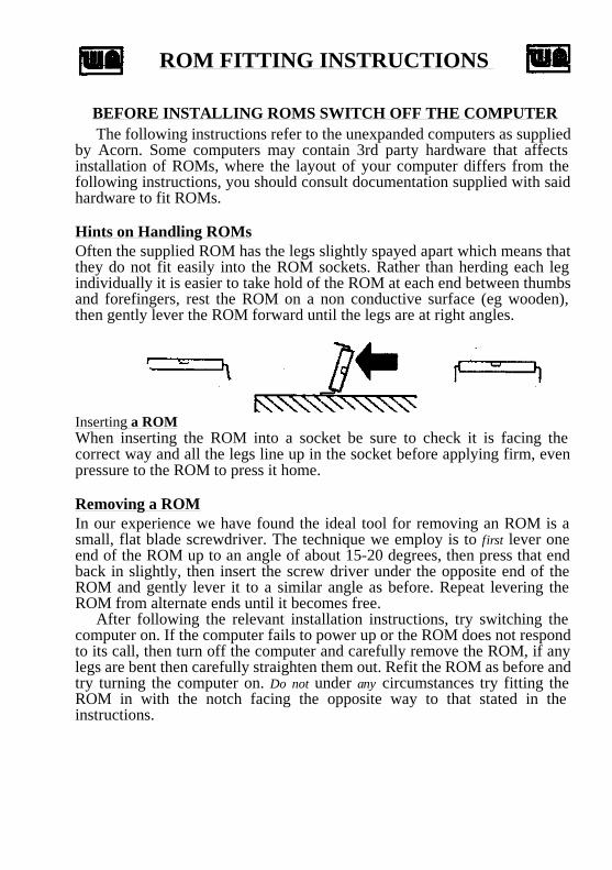
Hints on Handling ROMsOften the supplied ROM has the legs slightly spayed apart which means that they do not fit easily into the ROM sockets. Rather than herding each leg individually it is easier to take hold of the ROM at each end between thumbs and forefingers, rest the ROM on a non conductive surface (eg wooden), then gently lever the ROM forward until the legs are at right angles.
Inserting a ROMWhen inserting the ROM into a socket be sure to check it is facing the correct way and all the legs line up in the socket before applying firm, even pressure to the ROM to press it home.
Removing a ROMIn our experience we have found the ideal tool for removing an ROM is a small, flat blade screwdriver. The technique we employ is to first lever one end of the ROM up to an angle of about 15-20 degrees, then press that end back in slightly, then insert the screw driver under the opposite end of the ROM and gently lever it to a similar angle as before. Repeat levering the ROM from alternate ends until it becomes free.
After following the relevant installation instructions, try switching the computer on. If the computer fails to power up or the ROM does not respond to its call, then turn off the computer and carefully remove the ROM, if any legs are bent then carefully straighten them out. Refit the ROM as before and try turning the computer on. Do not under any circumstances try fitting the ROM in with the notch facing the opposite way to that stated in the instructions.
Fitting a ROM to a BBC Model B Computer
First remove 4 case screws (usually marked FIX) from computer, there are 2 at the back and 2 underneath the computer. Next remove the keyboard retention bolts.
In the bottom right hand corner of the computer you should see something resembling Figure 1.
The left most socket of the five (IC 51) contains the operating system marked PB04, this must not be moved. In one of the other 4 remaining sockets will be the BASIC ROM, for convenience this should be relocated to the right most socket (IC 101). The ROM can then be inserted into one of the 3 remaining sockets, making sure that you have the polarity notch facing towards the rear of the computer, ie the same way as the OS and BASIC.
Some BBC computers cannot switch between ROMs unless circuit changes are made. A TTL 74LS163 chip must be fitted into IC 76 and the PCB links S12 and S13 (located near the keyboard connector) Must be broken. A true BBC Model B should already have these circuit changes carried out.
Fittings ROM to BBC Model B Plus ComputerFirst remove 4 case screws (usually marked FIX) from computer, there are 2 at the back and 2 underneath the computer.
On the top left corner of the computer you should see a circuit layout resembling Figure 2.
The top right most socket (IC 71) of the 6 available contains the combined OS and BASIC ROM, this must not be moved. The sideways ROM may be inserted in to any of the 5 remaining sockets making sure the polarity notch on the ROM faces towards the rear of the computer, ie the same way as the combined OS/BASIC ROM. Under no circumstances plug a sideways ROM into IC sockets 29 and 37, as you will destroy them, these are for the Acorn speech upgrade only.
Links 9, 11, 12, 15 and 18 on the left hand side of computer correspond to sockets IC 35, 44, 57, 62 and 68 respectively. With the link made west the computer expects a 8/16K ROM to be present, with the link made east the computer expects a 32K ROM to be present.
Users may like to know that making link S13 from north to south, alters the logical ROM socket numbers of the BASIC and OS from 14 and 15 to 0 and 1. If 64K of sideways RAM is fitted then the 32K of sideways RAM normally mapped into sockets 0 and 1 will now be mapped into sockets 14 and 15.

Fitting a ROM to a BBC Master 128 ComputerFirst remove the 4 case screws labelled fix from the underside of the computer.
On the right hand side of the computer you should see a circuit lay out similar to Figure 3.
The uppermost socket houses the mega ROM, containing all the Master's standard software, this must not be moved. Normally the only socket that you can plug a 16K ROM into is IC 27 (the central one of the 3 available). When inserting the ROM make sure that the polarity notch on the ROM faces towards the left hand side of the computer ie. the same way as the mega ROM.
However it is possible to alter sockets IC 37 and IC 41 to accept ROMs by making links 19 and 18 respectively, east. This will however disable the 64K of sideways RAM.
The other alternative provided for is to use the ROM cartridge option. By inserting the sideways ROM into a ROM cartridge, making sure the polarity notch points towards the area marked pin 1, you then simply insert the cartridge into one of the slots on the top of the Master. It is only possible to insert the cartridge one way round.
Fitting a ROM to a BBC Master Compact ComputerFollowing the printed instructions on the underside of the Master Compact keyboard remove the 4 case screws. Carefully lift the top of the keyboard out of the way.
On the right hand side of the keyboard you should see a circuit layout similar to Figure 4.
The forward most ROM socket contains the Compact's mega ROM, this must not be moved. In a factory configured Compact only sockets IC 17, IC 23 and IC 29 can be used for normal 16K sideways ROMs, socket IC 38 is reserved for a 32K ROM device. Users wishing to use IC 38 for 16K sideways ROMs can change link PL11 from its north position to south.
When inserting the sideways ROM check the polarity notch is facing towards the left hand side of the keyboard ie the same way as the mega ROM.
Watford Electronics250 Lower High Street, Watford, Herts, WD1 2AN
TEL: 0923 37774 TELEX: 8956095 FAX: 01 950 8989


WATFORD ELECTRONICS32K RAM EXTENSION BOARD
FOR THE BBC MICRO
INTRODUCTION
The Watford Electronics 32K RAM Extension Board doubles the RAM capacity of the standard BBC Micro, and has been designed to fit in with existing products such as the Watford Electronics Double Density Disc System and ROM Expansion System.
It allows programs of up to 28K to run in any screen mode, thus avoiding the "No room" error message. This operation is completely transparent to the user and can be used in BASIC, VIEW, VIEWSHEET, WORDWISE 1.20 etc. Thus, long adventures can be written with full graphics.
Simultaneously, the board provides a 12K buffer, allowing two jobs to be done at the same time. This is ideal for word-processing as one text may be printed out while the next one is typed. The buffer can also use the full 32K of the RAM board, and can replace any of the buffers in the BBC Micro such as printer, RS423 or speech.
If you prefer to write your own software, full support has been provided for the user to use this memory for data storage.
The operating software in ROM and this manual are copyright (C) 1984 Ian Smith / WatfordElectronics.
1

CONTENTS
1. INSTALLATION 3
2. OPERATION 6
3. TECHNICAL SOFTWARE INFORMATION 16
4. TECHNICAL HARDWARE INFORMATION 22
5. ERROR MESSAGES 23
INDEX 24
2

1. INSTALLATION
First open the case of the BBC Micro by removing the four case screws. Two are at the back, and two under the keyboard. They may be marked FIX. Put the lid to one side and remove the bolts holding the keyboard. Remove the keyboard connector and loudspeaker connector and put the keyboard to one side.
With a screwdriver, remove IC1. This is labelled 6502 and is in the centre of the computer board. Plug it into the RAM board in the second socket from the right with the same orientation (notch north). If you do not have a RAM board with wires labelled "CLK", "REF" or "S19" (a MKI RAM board), then skip the next two paragraphs.
Remove IC86 which is just south of the keyboard connector, and plug in the IC attached to the RAM board. If you have IC86 soldered in, you will need to desolder the wires from the supplied chip and solder the wire coming from "REF" to pin 10 and the wire from "CLK" to pin 1. These are identical positions to those on the supplied IC.
Now pull out the connector on link S19 of the BBC Micro, which is located to the left of the 6502. In its place plug the wire coming from "S19" on the RAM board. The plug should push onto the centre terminal. If the link is soldered (on ISSUE 7 BBCs) then desolder it, solder a piece of wire into the centre terminal of about a quarter of an inch (7 mm) and plug the wire onto it.
Alternatively you could solder the wire directly onto the centre terminal.
3

Now take the supplied ribbon cable and plug one end into the 6502 socket making sure the red stripe is north. DO NOT BEND ANY PINS. Insert the other end into the rightmost socket on the RAM board with the red stripe north again. If you have another board which plugs in to the 6502 socket, then plug the ribbon into the board where the 6502 IC was originally positioned.
Now put the RAM board ROM into a sideways ROM socket, with the same orientation (notch north). These are located at the bottom right of the computer. If you have several ROMs in your machine, the RAM Board ROM should be put in the lowest priority socket. This is the fourth from the right of the case. However if you have a DFS ROM, put this in the lowest priority socket and put the RAM Board ROM next to it. The BASIC ROM should be in the highest priority socket (nearest the case). It is also necessary to make sure you have an OS 1.20 in your machine (found by typing *FXO).
The RAM board can easily lie in the computer or preferably it should be stuck to the lid by its self adhesive feet.
Now replace the keyboard, not forgetting the loudspeaker connector. Fit the lid and switch on the computer. The message "Watford Electronics 32K RAM" should appear.
If the computer does not come on properly, then switch off and check all connections - especially the keyboard connection! If the keyboard is not properly fitted then the screen will be blank apart from the flashing cursor, and a continuous buzz will be heard.
4

As you switch the machine on, it fully tests the RAM board and indicates if there is a fault. Should this be the case, check that all the ICs are plugged into the RAM board correctly.
5

2. OPERATION
To obtain a summary of the commands type *HELP RAM. All commands can be prefixed with a "W" to avoid clashes with other ROMs.
*BUFFERON (S/L) (0-8)
This command turns the buffer on and can have two optional suffixes.
"S" stands for a small 12K buffer and "L" stands for a large 32K buffer. If you require a large buffer you will need to turn off the RAM board with *RAMOFF.
The second suffix is the buffer number. This is the same number as for *FX21. The buffers are :
0 Keyboard1 RS423 input2 RS423 output3 Printer4 Sound channel 05 Sound channel 16 Sound channel 27 Sound channel 38 Speech
If you wish to change the buffer size or number during operation, you must type *BUFFEROFF first.
To obtain a summary of the *BUFFERON command, type *HELP BUFFERON.
6

*BUFFERON alone is equivalent to *BUFFERON S 3 which is a 12K printer buffer.
If the disc drive is accessed during buffer use, the buffer will deactivate itself in order toprotect its contents, for purely technicalreasons. To reactivate after disc use, type a dummy command appropriate for that buffer. In BASIC if the buffer was for the printer you would type CTRL-B' SPACE CTRL-C. If the buffer was for sound channel 1 you would type SOUND 1,0,0,0. In a wordprocessor you would print a space or some more text. Having done this, operation will contine as normal.
Some disc systems will need a disc access made since the last BREAK so that the buffer can function correctly. The easiest thing to do is *CAT.
The buffer is flexible enough to allow you to queue thousands of words, and it can save you having to slow down your typing if you type 100 characters a second! It is also useful for storing incoming data from the Watford Electronics Modem when used as buffer number 1.
The buffer replaces one of the BBC Micro's own internal buffers. Therefore all the bufferoperations are available on it. These operations include *FX 13,14,15,21,128,138,145,152. Thismeans you can use ADVAL(-n) to find the amount of space/number of characters in the buffer.
*BUFFEROFF
This command simply turns off the buffer.
7

*CLAIMON
This command allows the RAM board to take 256 bytes workspace (in a similar manner to a DFS) when you press BREAK. This raises PAGE by 256 bytes.
*CLAIMOFF
This command releases for the user the 256 bytes workspace used by the RAM board when you press BREAK. The command will automatically turn off the board, including the buffer, and PAGE will be reduced by 256 bytes. The other way of doing this is to press CTRL-BREAK.
8

*PURGEOFF
As the buffer is just an extension of the computer's buffer, all the operations on the buffer will work. These include the amount of space left and the ability to purge (clear) the buffer contents on ESCAPE, *FX15 etc. In certain cases this is undesirable for a large buffer, and so the use of this command will prevent the buffer from being purged.
*PURGEON
This enables purging of the buffer (default).
*PURGE
This purges the buffer even if *PURGEOFF has been typed. This is useful in a wordprocessor if something went wrong during printing as this would easily clear the buffer if you had purging disabled.
9

*RAMEDIT
This is a utility which is quite unique. It allowsthe user to look through memory in HEX and ASCII formats, while the screen is CONTINUOUSLY UPDATED, thus allowing the user to see the operating system in operation. The memory can be any sideways ROM or either RAM bank.
On typing *RAMEDIT a MODE 7 display appears. The flashing cursor is at the address entry point (default OSHWM). The address can be entered with the use of the arrow keys and the DELETE key. If you press TAB the cursor moves to the RAM bank selection. RAM bank 0 is the BBC memory and bank 1 is the RAM board memory. If you press TAB again the cursor moves to the ROM selection and a list of the active sideways ROMs in the machine is printed. If at any time you press RETURN the editor goes into the memory display mode.
On the right the ASCII characters are printed (or a full-stop if the character is outside the range 32-126). The cursor now flashes under the byte being edited. In the middle of the screen is the HEX tabulation of memory and there are two arrows either side of the byte being edited. If a key is pressed its ASCII value is entered into memory at the cursor position and the cursor will move to the right. In HEX entry mode, obtained by pressing TAB, the cursor does not move.
10

The keys are :
TAB ASCII/HEX entry toggleESCAPE return to entry modeCTRL-ESCAPE exit editorleft arrow move left one byteright arrow move right one byteup arrow move up one linedown arrow move down one lineSHIFT left arrow move to start of lineSHIFT right arrow move to end of lineSHIFT up arrow move up &80 bytesSHIFT down arrow move down &80 bytes
11

*RAMON
This command turns on the RAM board to free the memory normally used by the screen. BASIC gains this memory and consequently HIMEM is set to &8000 in any screen MODE. You will need to change screen MODE to inform BASIC of the change, or if there is no workspace already set aside, then you will need to press BREAK at the given message. In either case it is usually easier to press BREAK after typing *RAMON.
*RAMOFF
This command turns the RAM board off instantly, without affecting the buffer. BASIC can be informed of the change by changing MODE or by pressing BREAK.
12

*SLOAD
This directly replaces *LOAD for loading the screen. You must still specify the addresses, but the screen is automatically switched in and out. This is equally useful for loading data into data area 0.
*SSAVE
This directly replaces *SAVE for saving the screen in the same manner as *SLOAD.
An example of saving a MODE 2 screen is : *SSAVE screen 3000+5000
13

*XHELP
This lists all the sideways ROMs in the machine which are enabled and the sockets that they are in. This is usually quicker and simpler than *HELP because it is concise.
*XWORD
This combines *RAMON, *BUFFERON, *PURGEOFF and *WORD together for VIEW. If you press BREAK while in VIEW you must re-type *XWORD. If the RAM is not active you will get error number 0 : "Please press BREAK". You must press BREAK and re-type the command.
*XWORDWISE
This combines *RAMON, *BUFFERON, *PURGEOFF and *WORDWISE together. It is not necessary to re-type this if you press BREAK when in WORDWISE. If the RAM is not active you will get error number 0 : "Please press BREAK". You must press BREAK and re-type the command. This command will also work for WORDWISE-PLUS.
14

STATUS OF THE BOARD DURING OPERATION
To get a summary of the RAM board's status, type *HELP RAMSTATUS. This message applies to the BBC micro's end if you have a second processor.
On power up, the buffer is inactive and the RAM board is active.
On CTRL-BREAK the whole system is disabled and no workspace is claimed, which is usually necessary for games.
On BREAK the buffer and RAM board remain in the state they were in before BREAK, but the buffer is purged.
15

3. TECHNICAL SOFTWARE INFORMATION
The RAM board exists in parallel with the BBC's internal RAM and is switched with it in the same manner as the sideways ROM system, from address &0000 or &3000 to &7FFF. To obtain a summary of the OSBYTE and OSWORD calls type *HELP RAMFX.
*FX 32
This command is identical to *FX 132 but is used when the RAM board is active and the user wishes to find the highest available space in the current screen MODE. It is ideal for data storageprograms. The address is returned in X and Y.
*FX 33,X
This command is identical to *FX 133 but is used when the RAM board is active and the user wishes to find the highest available space in the screen MODE in the X register. The address is returned in X and Y.
16
*FX 34,X
This command is provided to switch between the RAM banks, but does not affect OS calls for screen operations etc. Data area 0 is the BBC's RAM which is used for some of the BASIC program and the screen memory. Data area 1 is the RAM board area and is used for the program. To switch to data area 1 use *FX 34,1 and to switch to data area 0 use *FX 34,0. This is ideal for loading data into either bank of RAM, but only applies to the top 20K. As the top half of your program disappears during this procedure (just like the sideways ROM system), the section of program doing this operation must be below &3000 in memory. This means your procedure must be fairly near the beginning of the program, or alternatively use *SLOAD and *SSAVE.
The full summary of OSBYTE 34 is : On entry :A=34
X :Bit 0=0 select BBC RAM .
1 select Watford RAMBit 6=0 write current state
1 read current stateBit 7=0 no stack operation
1 read operations : take state off stackwrite operations : put state onto stack
17

On exit :
A,X,Y are preserved, except on read operations where the value is returned in X.
The stack for past states is 8-deep and can be used thus :
*FX 34,128 : Select BBC RAM, saving old state.
*FX 34,192 : Select previous state.This is useful for screen dumps and other utilities which directly access the screen memory for speed.
18

*FX 35
This returns the location of the page workspace in X and Y.
*FX 36,X,Y
This reads/writes the RAM buffer number.New value=(old value AND Y) EOR X. So for a read X=0 and Y=&FF, for a write X=buffer number and Y=0. The former value is returned in X, and Y is preserved.
*FX 250,X,Y
This call is a read/write call for the RAM Board's status. New value=(old value AND Y) EOR X.
On entry :To read, X=0 and Y=&FF To write, X=value and Y=0
On exit :X=old value as follows :Bit 0=1 RAM board activeBit 1=1 Buffer activeBit 2=1 Buffer smallBit 3=1 Buffer largeBit 4=1 Purging disabledBit 5=1 NMI in useBit 6=1 Workspace at fixed locationBit 7=1 ROM claims workspace on BREAK
19

OSWORD &6E
This call reads a byte from the RAM Board. On entry :
A=&6EY,X=high, low byte of address of parameter block.YYXX+0 : low byte of address of byte to be read from
RAM Board.YYXX+1 : high byte of address.YYXX+2 : Bit 0 = 0/1. If address in range 0-&2FFF,read
data from data area 0/1. Bit 1 = 0/1. If address in range &3000-&7FFF, read data from data area 0/1.
On exit :
A,X,Y preserved.YYXX+3 : byte read from RAM Board
OSWORD &6F
This call is identical to OSBYTE &6E, except that on entry YYXX+3=byte to be written, and on exit YYXX+3=former contents of the memory location.
The OSWORD calls are essential if you want a large amount of apparently contiguous memory for data storage : YYXX+2 would be set to &01 so that memory locations 0-&2FFF in data area 1 and &3000-screen bottom in data area 0 would appear to be contiguous.
20

*MWS aaaa
This call moves the RAM Board workspace to the specified address page in HEX (eg *MWS 0A00). The call is necessary if you wish to set PAGE to &1100 with a DFS and still have the RAM Board active. The workspace should be in the range 0400-2F00. The workspace is not reset on BREAK, and can be moved when the RAM board and buffer are active. Thus after a BREAK, PAGE will go down by 256 bytes. To return the board to reclaiming memory in the usual way type *CLAIMON.
DIRECT CONTROL
For those programmers who want top speed, even though a speed decrease of less than 1% occurs, then there is another technique available. A write to &FFFF will select the Watford RAM and a write to &FFFE will select the BBC RAM. This applies for memory locations &3000 to &7FFF. To swap the whole memory write to &FFFC. This is a crude method and not normally advised as there are problems doing this - you must disable interrupts, and you can only do this from a sideways ROM.
Please note zero page loacations &00-&0F on the RAM board are reserved for the RAM Board ROM. All the zero page locations in the BBC RAM, which the ROM uses, are preserved.
21

4. TECHNICAL HARDWARE INFORMATION
The board adds very little extra load onto the power supply :MKI typ. 85 mA, max. 125 mAMKII typ. 155 mA, max. 175 mA
It will work happily with a fully populated ROM board, double disc drives, double density board etc. However, if the user still feels dubious then there is provision for an external 5v power supply. This can be wired into the two labelled holes and link S1 on the RAM board must be cut.
22

5. ERROR MESSAGES
0 : "Please press BREAK"
This message occurs when you have typed in a command where the RAM board needs to gain some workspace or relinquish it. The only way to overcome the problem is to press BREAK so that PAGE (OSHWM) can be set up to the new value.
160 : "Buffer too big"
This message occurs if you try *RAMON when you already have a large buffer, or if you try*BUFFER L when you have the RAM board on. You must decide what you want to do with the memory without flowing over the 32K
220 : "Syntax: BUFFERON (S/L) (0-8)"
This message is self-explanatory - you have not typed in the command correctly. "S" selects a small (12k) buffer and "L" a large (32k) buffer. 0-8 is the buffer number (see *FX21).You need not type the two options, in which case the default settings of S and 3 are assumed.
23

INDEX
A
ADVAL 7
B
BREAK 7,8,12,14,15,21,23Buffer 6,7,9,14,15,19,21,23BUFFEROFF 7BUFFERON 6,7,14,19,23Buffer too big 23
C
CAT 7CLAIMOFF 8CLAIMON 8,21CLK 3CTRL-BREAK 8,15
D
Direct control 21Disc 7
E
Error messages 23Escape 9
F
Fitting instructions 3FX 0 4FX 21 6,7FX 32 16FX 33 16
24

FX 34 13,17,18FX 35 19FX 36 19FX 250 19
G
Games 15
H
HELPBUFFERON 6RAM 6RAMFX 16RAMSTATUS 15
HIMEM 12
I
Installation 3
K
Keyboard 6
25

M
MK1 3,22MKII 3,22MODE 12,13,16MANS 21
0
OS 1.20 4OSBYTE 16,17,18,19OSHWM 8OSWORD 16,20
P
PAGE 8,21Please press BREAK 12,14Power consumption 22Powering up 4,5,15Prefix 6Printer 6,7PURGE 9PURGEOFF 9,14PURGEON 9
R
RAMEDIT 10,11RAMOFF 12,14RAMON 12Reactivation of buffer 7REF 3ROM position/priority 4RS423 6
S
S19 3Screen dumps 18SLOAD 13
26

SOUND 6,7Speed of operation 21SSAVE I3Stack 17,I8Status 15Syntax 23
T
Test of operation 5
W
Workspace 8,I2,14,15,19,21WORDWISE-PLUS 15
X
XHELP I4XWORD I4XWORDWISE I4
zero page 21
27