Embed Size (px)
Citation preview
International Journal of Engineering Sciences & Research
Technology (A Peer Reviewed Online Journal)
Impact Factor: 5.164
IJESRT
Chief Editor Executive Editor
Dr. J.B. Helonde Mr. Somil Mayur Shah
Website:www.ijesrt.com Mail: [email protected] O
Correspondence Address: 116, Sukhdev Nagar Ext-1, Airport Road, Indore – 452005, Madhya Pradesh, INDIA
IJESRT: 7(10), October, 2018 ISSN: 2277-9655
I X

ISSN: 2277-9655
[Ahamad * et al.,7(10): October, 2018] Impact Factor: 5.164
IC™ Value: 3.00 CODEN: IJESS7
http: // www.ijesrt.com© International Journal of Engineering Sciences & Research Technology
[30]
IJESRT INTERNATIONAL JOURNAL OF ENGINEERING SCIENCES & RESEARCH
TECHNOLOGY
USING A DYNAMIC VOLTAGE RESTORER (DVR) FOR REMOVAL OF
ABNORMALITIES DUE TOVOLTAGE SAG IN A DOUBLY FED TRANSMISSION
LINE Seraj Ahamad1, Ajit Kumar Verma2 & Balram Yadav3
*1M.tech. Scholar, Department of Electrical Engineering, Scope college of engineering, Bhopal 2Assistant Professor, Department of Electrical Engineering, Scope college of engineering, Bhopal
3HOD, Department of Electrical Engineering, Scope college of engineering, Bhopal
DOI: 10.5281/zenodo.1462685
ABSTRACT Changing electric load and higher power move in a wide interconnected framework prompts authentic, security
require in charge structure assignments moreover if a sudden accuse occurs there is an alteration in voltage profile
which can incite a sudden mischief on stack end. These voltage hangs are compensated at generator side by
various strategies anyway at the load end there is a probability. to keep up a vital separation from such hang at
stack side a tangle lab demonstrate is proposed in which a transmission line is sustained with two sources out of
which one is a breeze source and after that is subjected to a 3 organize fault. the voltage hang which happens is
compensated in the other model at same minute when DVR Dynamic voltage restorer is altered and is related at
the midpoint of framework. The results got exhibits that the voltage is compensated and profile is balanced, DVR
uses the essentialness source in all around facilitated way and implants nessacary AC voltage to arrange.
Keywords: DVR,matlab simulation ,short transmission line,DFIG
1. INTRODUCTION Power quality is of extraordinary significance in every cutting edge condition where power is included, control
quality can be basically impacted by an essential factor like quality administration. One of the real worries in
power industry today is control quality issues. By and by, the vast majority of the power quality issues are
because of various blame conditions. These conditions cause voltage hang, voltage swell, homeless people,
voltage intrusion and music. These issues may cause the mechanical assembly stumbling, shutdown business,
household and modern hardware, and miss procedure of drive framework.
2. POWER QUALITY PROBLEMS, CAUSES AND EFFECTS The various power quality problems are as followed:
(i) 1.Transients- A transient is a temporary occurrence of afault which is of a very short duration in a
system caused by the sudden change of state.
(ii) 2.Voltage sags- A voltage sag or voltage dip is a short duration reduction in rms voltage which can be
caused by a short circuit, overload or starting of electric motors.A voltage sag happens when the rms
voltage decreases between 10 and 90 percent of nominal voltage for one-half cycle to one minute
(iii) 3.Voltage swells- Voltage swell, which is a momentary increase in voltage, happens when a heavy load
turns off in a power system.
(iv) 4.Voltage interruption- Interruptions are classified as short-duration or long-duration variation.
The term interruption‖ is often used to refer to short-duration interruption, while the latter is
preceded by the wordsustained‖ to indicate a long-duration. They are measured and described by their
duration since the voltage magnitude is always less than 10% of nominal.
(v) 5.Harmonics- Harmonics is the integral multiple of frequencies voltages and currents in an electric
power system due to non linear loads. Harmonic frequencies in the power grid are a frequent
cause of power quality problems.

ISSN: 2277-9655
[Ahamad * et al.,7(10): October, 2018] Impact Factor: 5.164
IC™ Value: 3.00 CODEN: IJESS7
http: // www.ijesrt.com© International Journal of Engineering Sciences & Research Technology
[31]
Fig. I. Power Quality Problems
Causes of Power Quality Problems:
Transient – Due to Lightning, Turning major equipment on or off, back to back capacitor energization.
Voltage Sags – Due to starting of large Motors, Energization of heavy loads, incorrect VAR compensation.
Voltage Swells – Energizing a large capacitor bank, Switching off a large load, incorrect VAR compensation
Interruption – Faults (Short circuit), Equipment failures, Control malfunctions (attempting to isolate electrical
problem).
Harmonics – IT equipment, Variable frequency drives, Electro Magnetic Interference from appliances,
fluorescent lighting, Arc Furnace (Any non linear load).
Effects of Power Quality Problems:
Transient – Tripping, Processing error, Data loss, hardware reboot required, Component failure.
Voltage Sags--Dim lights, Equipment shutdown, Data error, shrinking display screens, Memory loss.
• Voltage Swells –Bright lights, Data error, shrinking display screens, Memory loss.
• Interruption – Faults, Equipment failures, Control malfunctions
• Harmonics – Line current increases, Losses increase, transformer and neutral conductor heating
leading to reduced equipment life span.
DFIG: Variable speed wind turbines are more popular than fixed speed one, due to its ability to capture more
energy from wind, improved power quality and reduced mechanical stress on the wind turbine. One of the most
frequently used generators with variable speed wind turbines is the DFIG which is an interesting alternative with
a growing market. It can run at variable speed but produce a voltage at the frequency of the grid. In contrast to a
conventional simple induction generator the electrical power generated by a DFIG is independent of the
speed.DFIG has various advantages like its low converter rating ( The converter rating of the DFIG is 25-30%
from the machine rating ) consequently its relatively high efficiency, lighter in weight, its low cost and its
capability of decoupling the control of both active and reactive power. Therefore, the DFIG has its distinguished
place among many variable speed wind turbine generators.
DFIG consists of a wound rotor induction generator (WRIG) and bidirectional back-to-back voltage source
converters. In this arrangement the stator is directly connected to the grid through a transformer while the rotor
winding is connected via slip rings. to the stator or the grid through the two back-to-back converters. The back-
to-back converter consists of two converters, i.e., rotor side converter (RSC) and grid side converter (GSC) (two
AC/DC insulated gate bipolar transistor (IGBT) based Voltage Source Converters (VSCs)). A DC link capacitor
is located between the two converters as energy storage, in order to maintain the variations (or ripple) in the DC
link voltage small. The main function of the RSC is to control the torque or the speed of the DFIG and also the
power factor at the stator terminals. On the other hand the function of the GSC is to keep the DC link voltage
constant also in some cases it may inject reactive power into the grid. The variable speed operation of the wind
turbine generator or the decoupling of the network electrical frequency from the rotor mechanical frequency is
obtained by the power converters by injecting a controllable voltage into the rotor circuit at slip frequency.

ISSN: 2277-9655
[Ahamad * et al.,7(10): October, 2018] Impact Factor: 5.164
IC™ Value: 3.00 CODEN: IJESS7
http: // www.ijesrt.com© International Journal of Engineering Sciences & Research Technology
[32]
Powerelectronic converter
DFIG Scheme
FIG system in MATLAB
Disadvantage of DFIG is it’s low voltage output which needs to be rectified. The control of the DFIG is mainly
obtained through the control of the RSC and GSC. Although vector control is usually used to control the DFIG
as it allows decoupling control of both active and reactive power and low THD, the direct control techniques
have a high dynamics response but with high THD.
During the voltage dips a very high voltage may be induced in the rotor circuit which depends on the level of the
voltage dip and also the type of the fault (Symmetrical or Asymmetrical). This high voltage may damage the
RSC and also the DC link capacitor, therefore it should be protected during the voltage dips.
For this purpose DVR is being utilized.
Dynamic voltage restorer: Dynamic voltage restorer (DVR) can provide the lucrative solution to mitigate
voltage sag by establishing the appropriate voltage quality level, necessary. It is recently being used as the active
solution for mitigation of power quality problems.
ISSN: 2277-9655
[Ahamad * et al.,7(10): October, 2018] Impact Factor: 5.164
IC™ Value: 3.00 CODEN: IJESS7
http: // www.ijesrt.com© International Journal of Engineering Sciences & Research Technology
[33]
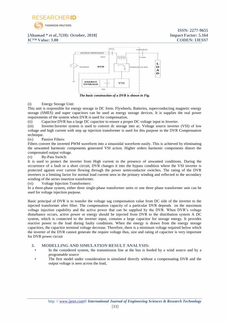
The basic construction of a DVR is shown in Fig.
(i) Energy Storage Unit:
This unit is responsible for energy storage in DC form. Flywheels, Batteries, superconducting magnetic energy
storage (SMES) and super capacitors can be used as energy storage devices. It is supplies the real power
requirements of the system when DVR is used for compensation.
(ii) Capacitor:DVR has a large DC capacitor to ensure a proper DC voltage input to Inverter.
(iii) Inverter:Inverter system is used to convert dc storage into ac. Voltage source inverter (VSI) of low
voltage and high current with step up injection transformer is used for this purpose in the DVR Compensation
technique.
(iv) Passive Filters:
Filters convert the inverted PWM waveform into a sinusoidal waveform easily. This is achieved by eliminating
the unwanted harmonic components generated VSI action. Higher orders harmonic components distort the
compensated output voltage.
(v) By-Pass Switch:
It is used to protect the inverter from High current in the presence of unwanted conditions. During the
occurrence of a fault or a short circuit, DVR changes it into the bypass condition where the VSI inverter is
protected against over current flowing through the power semiconductor switches. The rating of the DVR
inverters is a limiting factor for normal load current seen in the primary winding and reflected to the secondary
winding of the series insertion transformer.
(vi) Voltage Injection Transformers:
In a three-phase system, either three single-phase transformer units or one three phase transformer unit can be
used for voltage injection purpose.
Basic principal of DVR is to transfer the voltage sag compensation value from DC side of the inverter to the
injected transformer after filter. The compensation capacity of a particular DVR depends on the maximum
voltage injection capability and the active power that can be supplied by the DVR. When DVR’s voltage
disturbance occurs, active power or energy should be injected from DVR to the distribution system A DC
system, which is connected to the inverter input, contains a large capacitor for storage energy. It provides
reactive power to the load during faulty conditions. When the energy is drawn from the energy storage
capacitors, the capacitor terminal voltage decrease. Therefore, there is a minimum voltage required below which
the inverter of the DVR cannot generate the require voltage thus, size and rating of capacitor is very important
for DVR power circuit
3. MODELLING AND SIMULATION RESULT ANALYSIS: • In the considered system, the transmission line at the bus is feeded by a wind source and by a
programable source
• The first model under consideration is simulated directly without a compensating DVR and the
output voltage is seen across the load,

ISSN: 2277-9655
[Ahamad * et al.,7(10): October, 2018] Impact Factor: 5.164
IC™ Value: 3.00 CODEN: IJESS7
http: // www.ijesrt.com© International Journal of Engineering Sciences & Research Technology
[34]
Block diagram model of transmission line under consideration
• the transmission model in the second stage is subjected to a 3-phase fault artificially at the 6th
interval of running simulation and a large sag is seen.

ISSN: 2277-9655
[Ahamad * et al.,7(10): October, 2018] Impact Factor: 5.164
IC™ Value: 3.00 CODEN: IJESS7
http: // www.ijesrt.com© International Journal of Engineering Sciences & Research Technology
[35]
Proposed technique
DVR implemented in the transmission line
DVR with the changed ratings
• In the proposed technique, the DVR used in the MATLAB model is changed in such a way that the
ratings of IGBT’s 1,3, and 5 are kept 1.5 times the rating of 2,4,6
• In the second model the same condition is repeated but a DVR (dynamic voltage restorer) is used
in such a way that the condition above should be satisfied
• The result obtained by the DVR in transmission line removes the sag for a 3 phase fault from the
6th interval of transmission line

ISSN: 2277-9655
[Ahamad * et al.,7(10): October, 2018] Impact Factor: 5.164
IC™ Value: 3.00 CODEN: IJESS7
http: // www.ijesrt.com© International Journal of Engineering Sciences & Research Technology
[36]
4. RESULT ANALYSIS
Voltage sag due to 3-phase fault without DVR
Injected voltage by the DVR at the time of fault
Rectified output voltage after DVR action for the same line at same 3 phase fault condition
5. CONCLUSION In the areas were the transmission lines are subjected to more than one sources the problem of voltage sag is a
issue as some times in order to start the wind machines the machines take power from the grid. Also there are
many disturbances which leads to the voltage sag in the transmission line and which can be rectified using a
dynamic voltage restorer.DVR is formed by the switching combination of IGBT’s and if the manipulation is
done in these ratings then a better result is obtained

ISSN: 2277-9655
[Ahamad * et al.,7(10): October, 2018] Impact Factor: 5.164
IC™ Value: 3.00 CODEN: IJESS7
http: // www.ijesrt.com© International Journal of Engineering Sciences & Research Technology
[37]
REFERENCES [1] Anita Pakharia, Manoj Gupta ―Dynamic Voltage Restorer for Compensation of Voltaage Sag and
Swell: A Literature Review‖, International Journal of Advance in Engineering & Technology, vol 4, issue
1, july 2012, pp.347-355.
[2] Himadri Ghosh, Pradip kumarSaha, ― Design and Simulation of a Novel Self Supported Dynamic
Voltage Restorer (DVR) for Power Quality Improvement.‖ International Journal of Scientific &
Engineering Research, vol. 3, issue 6, june2012, pp 1-6.
[3] Mahmoud A. El-Gammal, Amr Y. Abou-Ghazala,―Dynamic Voltage Restorer for Voltage Sag
Mitigation‖ International Journal on Electrical Engineering and Informatics- volume-3, number 1, march
2011, pp 1-11.
[4] Rosli Omar, Nasrudin Abd Rahim, ― Mitigation of Voltage Sags/Swells Using Dynamic Voltage
Restorer (DVR)‖ ARPN Journal of Engineering and Applied Sciences, vol. 4, no. 4, june 2009, pp.50-56.
[5] M.N. Tandjaouli, C. Benachabia, ― Sensitive Loads Voltage Improvement Using Dynamic Voltage
Restorer‖ 2011 International Conference on Electrical Engineering and Informatics, Bandung, Indonesia,
17-19 July 2011.
[6] Ajay K. Damor, Prof. V. B. Babaria, ― Voltage Sag Control Using DVR‖, National Conference on
Recent Trends in Engineering & Technology‖ B. V. M. Engineering College, Gujrat, India, 13-14 may
2011.
[7] M. Arun Bhaskar, Dr. S.S. Dash ―Voltage Quality Improvement Using DVR‖ 2010 International
Conference on Resent Trends in Information, Telecommunication and computing. 2010,978-0-7695-
3975-1/10 $25.00 © 2010 IEEE, pp. 378-380.
[8] Saripalli Rajesh, Mahesh K. Mishra, ―Design and Simulation of Dynamic Voltage Restorer (DVR)
Using Sinusoidal Pulse Width Modulation (SPWM)‖ 16th National power systems conference, Osmania
University, Hyderabad, A.P. India, 15-17 december 2010, pp. 317-322.
[9] Ali O Al-Mathnani, Hussain Shareef ―Power Quality Improvement using DVR with Two Fast Vector
Control‖ The 4th International Power Engineering and Optimization Conf., Selangor, MALAYSIA,23-24
june 2010, pp. 376-381.
[10] Yash Pal, A. Swarup, Bhim Singh, “A Review of Compensating Type Custom Power Devices for Power
Quality Improvement”, 2008 IEEE 978-1-4244-1762-9/08.
[11] Roger C. Dugan, Mark F. McGranaghan, Surya Santoso, H. Wayne Beaty, ― Electrical Power Systems
Quality‖ Tata McGraw Hills publications, 3rd Edition 2012
CITE AN ARTICLE
Ahamad, S., Verma, A. K., & Yadav, B. (2018). USING A DYNAMIC VOLTAGE RESTORER
(DVR) FOR REMOVAL OF ABNORMALITIES DUE TOVOLTAGE SAG IN A DOUBLY FED
TRANSMISSION LINE. INTERNATIONAL JOURNAL OF ENGINEERING SCIENCES &
RESEARCH TECHNOLOGY, 7(10), 30-37.


![JESRT: 8(2), February, 2019 ISSN: 2277-9655 I ...ijesrt.com/issues /Archive-2019/February-2019/10.pdfISSN: 2277-9655 [Benti * et al., 8(2): February, 2019] Impact Factor: 5.164 IC™](https://img.pdfslide.us/doc/110x75/60644a4e76320a514046a979/jesrt-82-february-2019-issn-2277-9655-i-archive-2019february-201910pdf.jpg)

![JESRT: 8(1), January, 2019 ISSN: 2277-9655 I nternational …ijesrt.com/issues /Archive-2019/january-2019/38.pdf · proves potential in the management of urolithiasis [6, 7]. Antioxidants](https://img.pdfslide.us/doc/110x75/5caea69188c99323378c8bd8/jesrt-81-january-2019-issn-2277-9655-i-nternational-archive-2019january-201938pdf.jpg)

![ISSN: 2277-9655 (I2OR), Publication Impact Factor: 3.785 ... /Archive-2016/January-2016/82.pdf · [Adari, 5(1): January, 2016] ISSN: 2277-9655 (I2OR), Publication Impact Factor: 3.785](https://img.pdfslide.us/doc/110x75/5b515b5b7f8b9a6b118bf4f6/issn-2277-9655-i2or-publication-impact-factor-3785-archive-2016january-201682pdf.jpg)


![JESRT: 9(5), May, 2020 ISSN: 2277-9655 I International ... /Archive-2020/May-2020/2.pdf · ISSN: 2277-9655 [Kabeyi et al., 9(5): May, 2020] Impact Factor: 5.164 IC™ Value: 3.00](https://img.pdfslide.us/doc/110x75/5f0882f77e708231d4225fc8/jesrt-95-may-2020-issn-2277-9655-i-international-archive-2020may-20202pdf.jpg)